chapter 11 surface chemistry in the petroleum industry · surface chemistry in the petroleum...
TRANSCRIPT
CHAPTER 11
Surface Chemistry in the PetroleumIndustryJames R. Kanicky, Juan-Carlos Lopez-Montilla, Samir Pandey andDinesh O. ShahCenter for Surface Science and Engineering, Departments of Chemical Engineering and Anesthesiology,University of Florida, Gainesville, Florida, USA
1 Introduction . . . . . . . . . . . . . . . . . . . . . . . 2512 Fundamentals . . . . . . . . . . . . . . . . . . . . . . 252
2.1 Adsorbed films . . . . . . . . . . . . . . . . . 2522.2 Self-assembly of surfactant
molecules . . . . . . . . . . . . . . . . . . . . . 2522.3 Contact angle and wetting . . . . . . . . . 2542.4 Foams . . . . . . . . . . . . . . . . . . . . . . . 2542.5 Emulsions . . . . . . . . . . . . . . . . . . . . 256
2.5.1 Hydrophilic–lipophilicbalance (HLB) . . . . . . . . . . . . 257
2.5.2 Winsor’s R ratio . . . . . . . . . . 2582.5.3 Phase-inversion
temperature . . . . . . . . . . . . . . 2582.5.4 Surfactant affinity
difference . . . . . . . . . . . . . . . 2582.5.5 Microemulsions . . . . . . . . . . . 258
3 Applications . . . . . . . . . . . . . . . . . . . . . . . 259
3.1 Drilling mud . . . . . . . . . . . . . . . . . . 2593.2 Enhanced oil recovery . . . . . . . . . . . 259
3.2.1 Surfactant–polymerflooding . . . . . . . . . . . . . . . . 259
3.2.2 Foams in enhanced oilrecovery . . . . . . . . . . . . . . . . 262
3.2.3 Acid fracturing for oil wellstimulation . . . . . . . . . . . . . . 263
3.3 Antifoaming and defoaming . . . . . . . 2633.4 Corrosion inhibition . . . . . . . . . . . . . 2633.5 Oil spill clean-up . . . . . . . . . . . . . . . 2643.6 Fluidization of bitumen . . . . . . . . . . . 2653.7 Asphaltic emulsions . . . . . . . . . . . . . 2653.8 Oil/water separation and crude oil
dehydration . . . . . . . . . . . . . . . . . . . 2654 Summary . . . . . . . . . . . . . . . . . . . . . . . . . 2665 References . . . . . . . . . . . . . . . . . . . . . . . . 266
1 INTRODUCTION
It is well recognized that the energy consumption percapita and the standard of living of a society areinterrelated. Among various sources of energy, fossilfuels or crude oils play an important role in providingthe energy supply of the world. Crude oil is themost readily exploitable source of energy availableto humankind, and is also a source of raw materialsfor feed stocks in many of the chemical industrieson which our present civilization relies. The fieldof surface chemistry is intricately connected to most
(if not all) processes of petroleum technology – fromthe drilling of crude oil to petroleum refining andpetrochemical processing – as well as to allied anddependent applications and industries. All of theseprocesses involve interfacial phenomena and surfacechemical interactions.
In the context of petroleum technology, surfacechemistry deals with the surface properties of crudeoil/air, crude oil/brine (or water) and crude oil/solid sur-faces. Thus, surface tension, interfacial tension (IFT),contact angle, wetting and surface charge (zeta potential)are the parameters that one measures for surface
Handbook of Applied Surface and Colloid Chemistry. Edited by Krister HolmbergISBN 0471 490830 2001 John Wiley & Sons, Ltd
252 SURFACE CHEMISTRY IN IMPORTANT TECHNOLOGIES
chemical studies. The next section deals with thefundamental aspects of surface chemistry and how theyrelate to the petroleum industry. Following this dis-cussion, we will describe several major areas in thepetroleum industry – enhanced oil recovery, corrosioninhibition, oil spill clean-up, fluidization of bitumen,asphaltic emulsions, oil/water separation and crude oildehydration – where knowledge of surface chemistryplays a vital role.
2 FUNDAMENTALS
A surfactant molecule has two functional groups,namely a hydrophilic (water-soluble) or polar groupand a hydrophobic (oil-soluble) or non-polar group.The hydrophobic group is usually a long hydrocarbonchain (C8 –C18), which may or may not be branched,while the hydrophilic group is formed by moieties suchas carboxylates, sulfates, sulfonates (anionic), alcohols,polyoxyethylenated chains (nonionic) and quaternaryammonium salts (cationic) (1). Crude oil contains organicacids and salts, alcohols and other natural surface-activeagents. When crude oil is brought in contact with brineor water, these natural surfactants accumulate at theinterface and form an adsorbed film which lowers theinterfacial tension of the crude oil/water interface.
Depending on the type of crude oil, the adsorbed filmat the interface can be either fluid or very viscoelasticand able to form a skin. Depending on the propertiesof the crude oil (e.g. API gravity (2), sulfur, salt andmetals content, viscosity, pour point, etc.), the struc-ture of the film can vary significantly. Therefore, themolecular packing, surface viscosity, surface elasticityand surface charge of the adsorbed film are very impor-tant parameters that determine various phenomena suchas coalescence of emulsion droplets, as well as oil dropmigration in porous media.
2.1 Adsorbed films
Adsorption is an entropically driven process by whichmolecules diffuse preferentially from a bulk phaseto an interface. Due to the affinity that a surfactantmolecule encounters towards both polar and non-polarphases, thermodynamic stability (i.e. a minimum in freeenergy or maximum in entropy of the system) occurswhen these surfactants are adsorbed at a polar/non-polar(e.g. oil/water or air/water) interface. The differencebetween solute concentration in the bulk and that at theinterface is the surface excess concentration. The latter
is related to surface and interfacial tension by the GibbsAdsorption Equation (3–5), which in its practical form,is as follows:
� = − 1
RT
dγ
d lnC(11.1)
where � is the surface excess per unit area (moles/cm2)of surfactant measured, R the universal gas constant,T the temperature (in kelvin), γ the surface tension(often replaced by σ for interfacial tension), and C
the bulk concentration of surface-active species. Oncethe surface excess � is known, the area per moleculeof adsorbed surfactant can be calculated by using thefollowing equation:
Area per molecule(A2) = 1016
NA�(11.2)
with units of area/molecule in A2/molecule, and where
NA is the Avogadro constant (6.023 × 10²³ moleculesper mole).
The Gibbs adsorption equation allows for calculationof area per molecule from very simple measurementsof surface (or interfacial) tension versus surfactantconcentration in the solution. This calculation, in turn,enables one to study the relative area/molecule of asurfactant. Tighter molecular packing in the adsorbedfilm lowers the interfacial tension.
In addition, for very surface-active molecules, aslight increase in bulk phase concentration produces adramatic reduction in the interfacial tension.
With the use of specific surfactants, and with appro-priate physico-chemical conditions, the interfacial ten-sion of a crude oil/water interface can drop as lowas 10−4 mN/m (6). As will be discussed below, suchultra-low interfacial tensions are very important in tech-nologies such as enhanced oil recovery processes forrecovering crude oil from depleted oil wells.
The presence of surfactant molecules at an interfaceleads to a dramatic change in many surface properties,including surface and interfacial tensions (as discussedabove), contact angle, wettability, surface charge andsurface rheology (i.e. surface viscosity). Surfactants canalso act as a barrier when they adsorb at an interface,thus influencing mass and heat transfer between theadjacent phases as well as dispersion stability (1).
2.2 Self-assembly of surfactant molecules
The adsorption of surface-active molecules from a bulkphase to a surface or interface is governed by an equi-librium rate constant, and the adsorption occurs at any
SURFACE CHEMISTRY IN THE PETROLEUM INDUSTRY 253
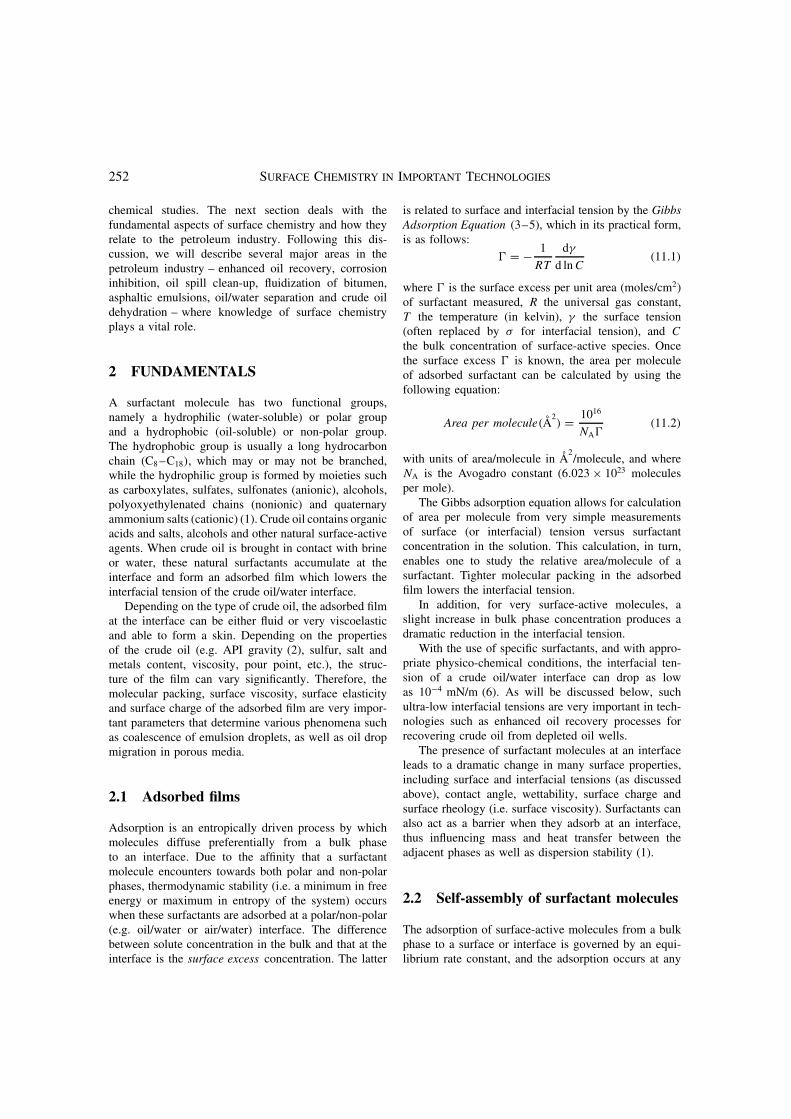
concentration. If the concentration of a soluble surfactantin water is increased gradually, the surface concentrationalso increases and reaches a maximum level at a specificbulk concentration. Beyond this concentration, individ-ual surfactant monomers begin to aggregate with theirhydrophilic heads pointing outwards towards the solu-tion and the hydrophobic tails pointing inwards awayfrom the water in order to minimize the free energy(i.e. maximize the entropy) of the system. The concen-tration at which this aggregation occurs is called thecritical micelle concentration (CMC), and the aggregatesare called micelles. In general, micelles are sphericalaggregates of surfactant molecules about 4–10 nm indiameter that are in equilibrium with single surfactantmonomers in the bulk aqueous solution (Figure 11.1).The critical micelle concentration depends upon thestructure of surfactant molecules, as well as physico-chemical conditions such as temperature, pH and theionic composition of the solution.
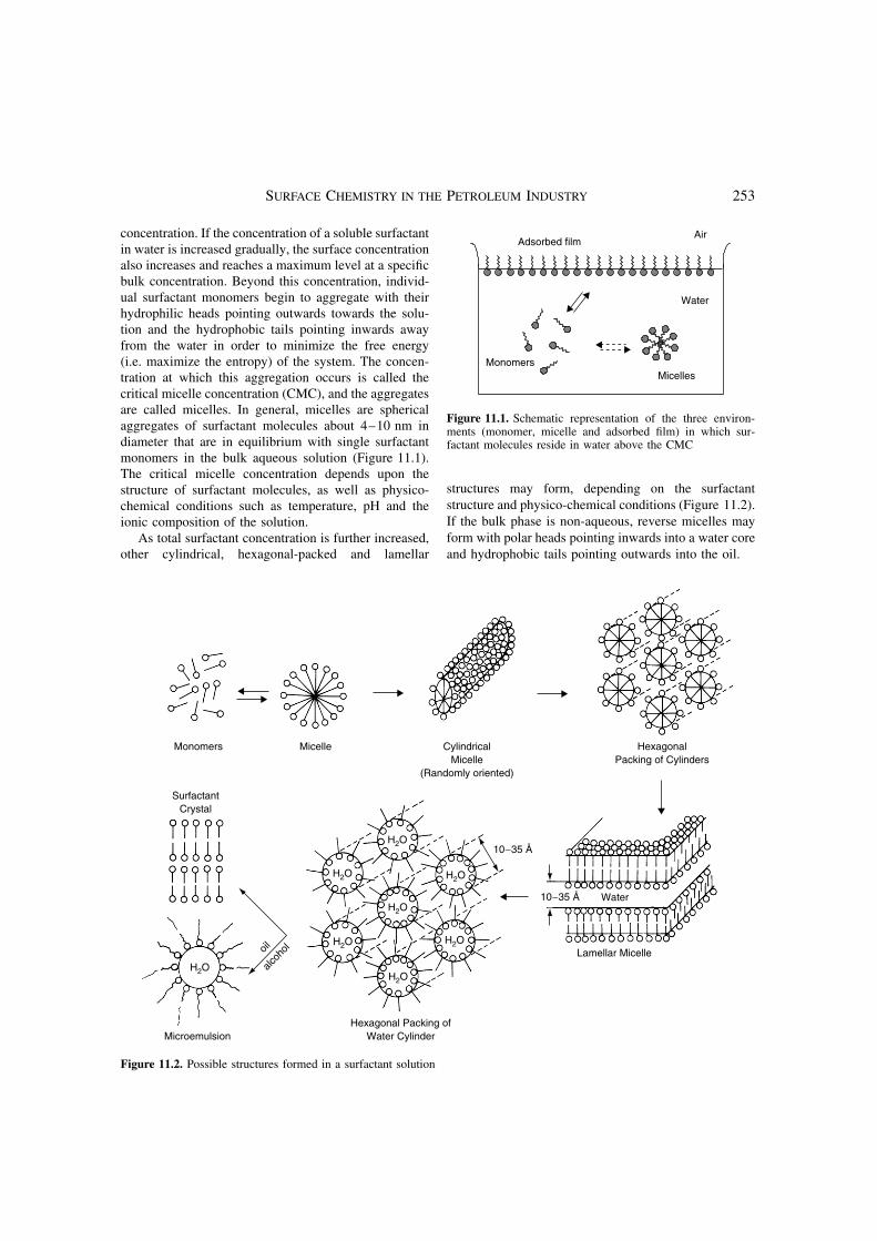
As total surfactant concentration is further increased,other cylindrical, hexagonal-packed and lamellar
MicellesMonomers
Adsorbed film
Water
Air
Figure 11.1. Schematic representation of the three environ-ments (monomer, micelle and adsorbed film) in which sur-factant molecules reside in water above the CMC
structures may form, depending on the surfactantstructure and physico-chemical conditions (Figure 11.2).If the bulk phase is non-aqueous, reverse micelles mayform with polar heads pointing inwards into a water coreand hydrophobic tails pointing outwards into the oil.
Microemulsion
oil
alcoh
ol
H2OH2O
H2O
H2O
H2O
H2O
H2O
H2O
Hexagonal Packing ofWater Cylinder
Lamellar Micelle
10−35 Å
10−35 Å
Water
HexagonalPacking of Cylinders
CylindricalMicelle
(Randomly oriented)
MicelleMonomers
SurfactantCrystal
Figure 11.2. Possible structures formed in a surfactant solution
254 SURFACE CHEMISTRY IN IMPORTANT TECHNOLOGIES
When an oil phase is present in contact with theaqueous phase, the water/oil partition coefficient ofthe surfactant, degree of surface activity and molecularstructure determine whether an oil-in-water (o/w) emul-sion, water-in-oil (w/o) emulsion, or liquid crystallinestructure is formed (1).
Surfactant aggregates are dynamic systems. Thermalenergy and coulombic forces keep surfactant monomersand aggregates in motion, and influence the rates offormation and break-up of these structures. Micel-lar systems, for example, exhibit two characteristic“relaxation” times, known as τ1 and τ2, correspondingto the rate at which single monomers enter and exita micellar aggregate, and to the rate of formation andbreak-up of an entire micelle, respectively. The kinet-ics of micellization has been shown to strongly affectsuch interfacial phenomena as wetting time, foamability,emulsion droplet size, oil solubilization rate and deter-gency (7).
2.3 Contact angle and wetting
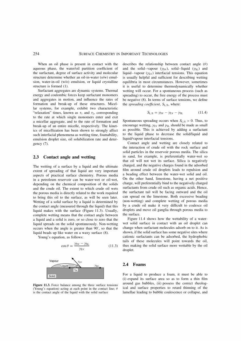
The wetting of a surface by a liquid and the ultimateextent of spreading of that liquid are very importantaspects of practical surface chemistry. Porous mediain a petroleum reservoir can be water-wet or oil-wet,depending on the chemical composition of the solidsand the crude oil. The extent to which crude oil wetsthe porous media is directly related to the work requiredto bring this oil to the surface, as will be seen later.Wetting of a solid surface by a liquid is determined bythe contact angle (measured through the liquid) that thisliquid makes with the surface (Figure 11.3). Usually,complete wetting means that the contact angle betweena liquid and a solid is zero, or so close to zero that theliquid spreads on the solid spontaneously. Non-wettingoccurs when the angle is greater than 90°, so that theliquid beads up like water on a waxy surface (8).
Young’s equation, as follows:
cos θ = γSV − γSL
γLV(11.3)
Solid
gSL
gLV
gSVq
Vapour
Liquid
Figure 11.3. Force balance among the three surface tensions(Young’s equation) acting at each point in the contact line; θis the contact angle of the liquid with the solid surface
describes the relationship between contact angle (θ )and the solid–vapour (γSV), solid–liquid (γSL) andliquid–vapour (γLV) interfacial tensions. This equationis usually helpful and sufficient for describing wettingequilibria in most circumstances. However, sometimesit is useful to determine thermodynamically whetherwetting will occur. For a spontaneous process (such asspreading) to occur, the free energy of the process mustbe negative (8). In terms of surface tensions, we definethe spreading coefficient, SL/S, where:
SL/S = γSV − γLV − γSL (11.4)
Spontaneous spreading occurs when SL/S > 0. Thus, toencourage wetting, γLV and γSL should be made as smallas possible. This is achieved by adding a surfactantto the liquid phase to decrease the solid/liquid andliquid/vapour interfacial tensions.
Contact angle and wetting are closely related tothe interaction of crude oil with the rock surface andsolid particles in the reservoir porous media. The silicain sand, for example, is preferentially water-wet sothat oil will not wet its surface. Silica is negativelycharged, and the negative charges found in the adsorbedfilm around crude oil droplets leads to repulsion anda beading effect between the water-wet solid and oil.On the other hand, limestone, having a net positivecharge, will preferentially bind to the negatively chargedsurfactants from crude oil such as organic acids. Hence,the surfactant tail will be facing outward and the oilcan spread on the limestone. Both excessive beading(non-wetting) and complete wetting of porous mediaby a crude oil make it very difficult to coalesce oildroplets and move oil ganglia through porous media tothe surface.
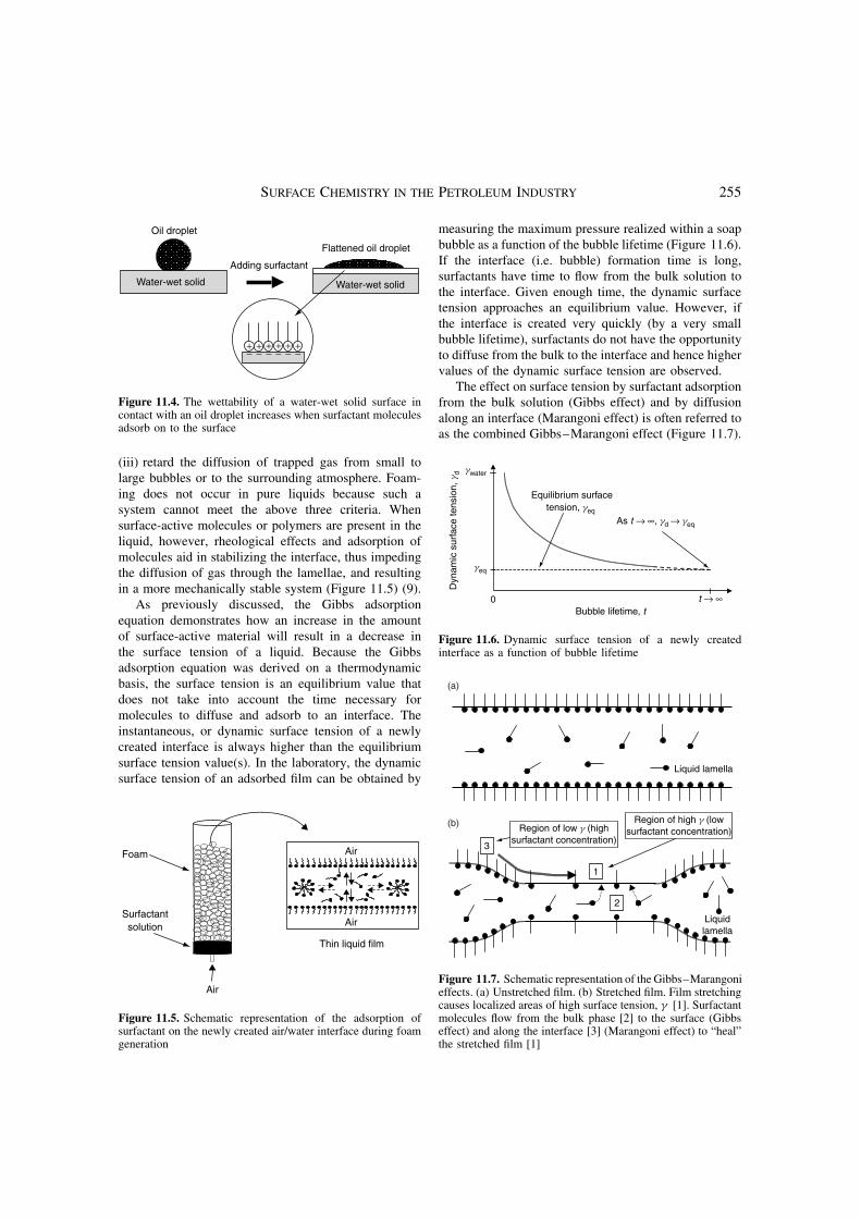
Figure 11.4 shows how the wettability of a water-wet solid surface in contact with an oil droplet canchange when surfactant molecules adsorb on to it. As isshown, if the solid surface has some negative sites wherecationic surfactants can be adsorbed, the hydrophobictails of these molecules will point towards the oil,thus making the solid surface more wettable by the oildroplet.
2.4 Foams
For a liquid to produce a foam, it must be able to(i) expand its surface area so as to form a thin filmaround gas bubbles, (ii) possess the correct rheolog-ical and surface properties to retard thinning of thelamellae leading to bubble coalescence or collapse, and
SURFACE CHEMISTRY IN THE PETROLEUM INDUSTRY 255
+ + ++ + +− −−− − −
Water-wet solid
Flattened oil droplet
Adding surfactant
Oil droplet
Water-wet solid
Figure 11.4. The wettability of a water-wet solid surface incontact with an oil droplet increases when surfactant moleculesadsorb on to the surface
(iii) retard the diffusion of trapped gas from small tolarge bubbles or to the surrounding atmosphere. Foam-ing does not occur in pure liquids because such asystem cannot meet the above three criteria. Whensurface-active molecules or polymers are present in theliquid, however, rheological effects and adsorption ofmolecules aid in stabilizing the interface, thus impedingthe diffusion of gas through the lamellae, and resultingin a more mechanically stable system (Figure 11.5) (9).
As previously discussed, the Gibbs adsorptionequation demonstrates how an increase in the amountof surface-active material will result in a decrease inthe surface tension of a liquid. Because the Gibbsadsorption equation was derived on a thermodynamicbasis, the surface tension is an equilibrium value thatdoes not take into account the time necessary formolecules to diffuse and adsorb to an interface. Theinstantaneous, or dynamic surface tension of a newlycreated interface is always higher than the equilibriumsurface tension value(s). In the laboratory, the dynamicsurface tension of an adsorbed film can be obtained by
Foam
Surfactantsolution
Thin liquid film
Air
Air
Air
Figure 11.5. Schematic representation of the adsorption ofsurfactant on the newly created air/water interface during foamgeneration
measuring the maximum pressure realized within a soapbubble as a function of the bubble lifetime (Figure 11.6).If the interface (i.e. bubble) formation time is long,surfactants have time to flow from the bulk solution tothe interface. Given enough time, the dynamic surfacetension approaches an equilibrium value. However, ifthe interface is created very quickly (by a very smallbubble lifetime), surfactants do not have the opportunityto diffuse from the bulk to the interface and hence highervalues of the dynamic surface tension are observed.
The effect on surface tension by surfactant adsorptionfrom the bulk solution (Gibbs effect) and by diffusionalong an interface (Marangoni effect) is often referred toas the combined Gibbs–Marangoni effect (Figure 11.7).
0
Equilibrium surfacetension, geq
Bubble lifetime, tt → ∞
As t → ∞, gd → geq
geq
gwater
Dyn
amic
sur
face
tens
ion,
gd
Figure 11.6. Dynamic surface tension of a newly createdinterface as a function of bubble lifetime
2
1
3
Region of low g (highsurfactant concentration)
Region of high g (lowsurfactant concentration)
Liquid lamella
Liquidlamella
(a)
(b)
Figure 11.7. Schematic representation of the Gibbs–Marangonieffects. (a) Unstretched film. (b) Stretched film. Film stretchingcauses localized areas of high surface tension, γ [1]. Surfactantmolecules flow from the bulk phase [2] to the surface (Gibbseffect) and along the interface [3] (Marangoni effect) to “heal”the stretched film [1]
256 SURFACE CHEMISTRY IN IMPORTANT TECHNOLOGIES
As a foam lamella is stretched (e.g. by gravity, agita-tion, thermal fluctuation or drainage), it becomes thinnerand a new surface is generated having a lower transientsurfactant concentration at the surface, and consequentlya higher surface tension, than its neighbouring surface.The surface tension gradient that is generated results inthe flow of surfactant (and associated boundary layerwater) from areas of low γ to those of high γ , therebyopposing film thinning. Likewise, the diffusion of sur-factant molecules with associated water also occurs fromthe bulk in the direction of the newly created surface.These mechanisms can be thought of as producing a“healing” effect at the site of thinning. While the Gibbsand Marangoni effects are complementary, each of themare generally important in different surfactant concen-tration regimes. However, both mechanisms rely on thepresence of a surface tension gradient and are ineffectiveat very low and very high surfactant concentrations. Atvery low surfactant concentrations, not enough surfac-tant monomers exist in the bulk or interface to diffuseto the thinning film. At very high concentrations, somany monomers are present in the system that an ade-quate concentration gradient is not established betweenthe thinning film and the bulk and neighbouring sur-faces.
Other factors can also affect the stability of foam;among these are temperature, surfactant structure, sur-face viscosity, rate of drainage and bulk viscosity.
2.5 Emulsions
Working with emulsion systems is nothing new to peoplein the petroleum industry. Historically and economi-cally, the most important problems in the oil industryhave been in the area of breaking up o/w emulsionsformed within reservoirs. However, the breaking andformation of emulsions plays a very important role inother technological applications in the oil industries.Because of their wide-ranging practical importance, it isnecessary to discuss the fundamental aspects and meth-ods of characterization of emulsions.
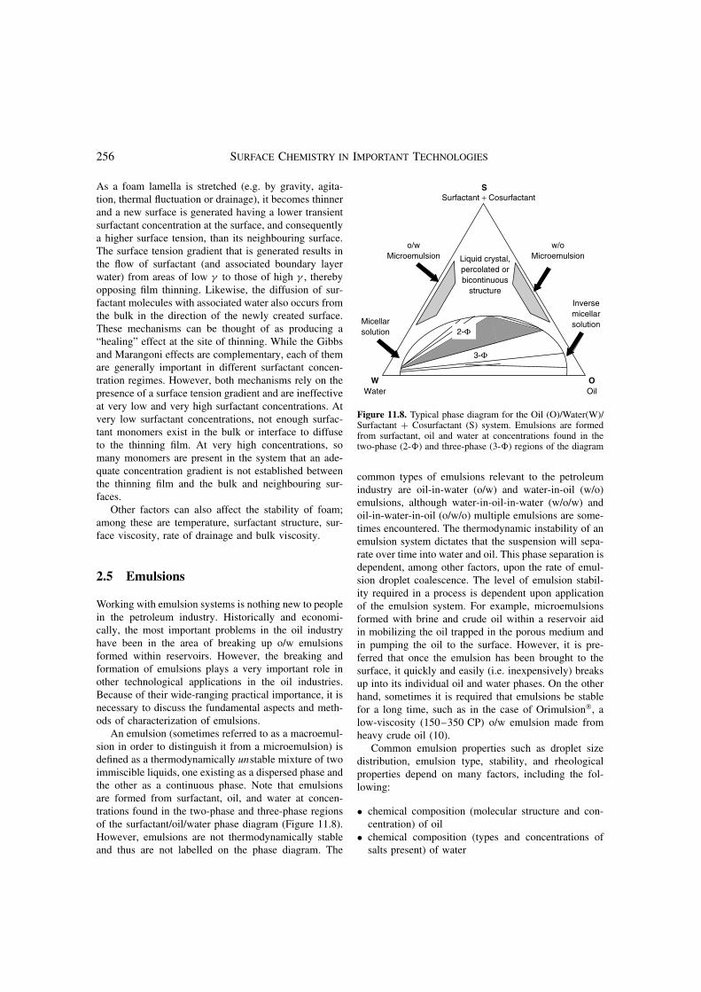
An emulsion (sometimes referred to as a macroemul-sion in order to distinguish it from a microemulsion) isdefined as a thermodynamically unstable mixture of twoimmiscible liquids, one existing as a dispersed phase andthe other as a continuous phase. Note that emulsionsare formed from surfactant, oil, and water at concen-trations found in the two-phase and three-phase regionsof the surfactant/oil/water phase diagram (Figure 11.8).However, emulsions are not thermodynamically stableand thus are not labelled on the phase diagram. The
WWater
OOil
3-Φ
2-ΦMicellarsolution
Inversemicellarsolution
o/wMicroemulsion
w/oMicroemulsion
Surfactant + CosurfactantS
Liquid crystal,percolated orbicontinuous
structure
Figure 11.8. Typical phase diagram for the Oil (O)/Water(W)/Surfactant + Cosurfactant (S) system. Emulsions are formedfrom surfactant, oil and water at concentrations found in thetwo-phase (2-�) and three-phase (3-�) regions of the diagram
common types of emulsions relevant to the petroleumindustry are oil-in-water (o/w) and water-in-oil (w/o)emulsions, although water-in-oil-in-water (w/o/w) andoil-in-water-in-oil (o/w/o) multiple emulsions are some-times encountered. The thermodynamic instability of anemulsion system dictates that the suspension will sepa-rate over time into water and oil. This phase separation isdependent, among other factors, upon the rate of emul-sion droplet coalescence. The level of emulsion stabil-ity required in a process is dependent upon applicationof the emulsion system. For example, microemulsionsformed with brine and crude oil within a reservoir aidin mobilizing the oil trapped in the porous medium andin pumping the oil to the surface. However, it is pre-ferred that once the emulsion has been brought to thesurface, it quickly and easily (i.e. inexpensively) breaksup into its individual oil and water phases. On the otherhand, sometimes it is required that emulsions be stablefor a long time, such as in the case of Orimulsion, alow-viscosity (150–350 CP) o/w emulsion made fromheavy crude oil (10).
Common emulsion properties such as droplet sizedistribution, emulsion type, stability, and rheologicalproperties depend on many factors, including the fol-lowing:
• chemical composition (molecular structure and con-centration) of oil
• chemical composition (types and concentrations ofsalts present) of water
SURFACE CHEMISTRY IN THE PETROLEUM INDUSTRY 257
• chemical composition (nonionic, anionic, cationic,zwitterionic and polymeric) and concentration ofsurfactants
• structure and concentration of cosurfactants (e.g.short-chain alcohols)
• number and types of finely divided particles present• temperature and pressure of the system• order of mixing of emulsion constituents• energy input.
It is clearly evident that emulsions are very compli-cated systems. Progress has been made on theoreticalstudies attempting to clarify the complexities of thesesystems. However, the majority of predictions of thetype and stability of emulsions derives more from empir-ical observation than from theory. Emulsion formulationis still considered to be an art rather than a scientificmethod in many circles of industry (11).
2.5.1 Hydrophilic–lipophilic balance (HLB)
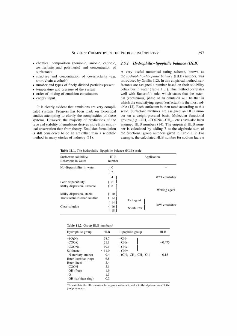
A very useful numerical rating scheme, known asthe hydrophilic–lipophilic balance (HLB) number, wasintroduced by Griffin (12). In this empirical method, sur-factants are assigned a number based on their solubilitybehaviour in water (Table 11.1). This method correlateswell with Bancroft’s rule, which states that the exter-nal (continuous) phase of an emulsion will be that inwhich the emulsifying agent (surfactant) is the most sol-uble (13). Each surfactant is then rated according to thisscale. Surfactant mixtures are assigned an HLB num-ber on a weight-prorated basis. Molecular functionalgroups (e.g. –OH, –COONa, –CH2–, etc.) have also beenassigned HLB numbers (14). The empirical HLB num-ber is calculated by adding 7 to the algebraic sum ofthe functional group numbers given in Table 11.2. Forexample, the calculated HLB number for sodium laurate
Table 11.1. The hydrophilic–lipophilic balance (HLB) scale
Surfactant solubility/ HLB ApplicationBehaviour in water number
No dispersibility in water 0 –{
2
4 W/O emulsifier}
Poor dispersibility { 6Milky dispersion, unstable { 8
Wetting agent
Milky dispersion, stable { 10Translucent-to-clear solution { 12
}Detergent
14
O/W emulsifierClear solution
{16
}Solubilizer
18
Table 11.2. Group HLB numbersa
Hydrophilic group HLB Lipophilic group HLB
–SO4Na 38.7 –CH––COOK 21.1 –CH2– −0.475
–COONa 19.1 –CH3–
Sulfonate ∼ 11.0 –CH=–N (tertiary amine) 9.4 –(CH2–CH2–CH2–O–) −0.15Ester (sorbitan ring) 6.8Ester (free) 2.4–COOH 2.1–OH (free) 1.9–O– 1.3–OH (sorbitan ring) 0.5
aTo calculate the HLB number for a given surfactant, add 7 to the algebraic sum of thegroup numbers.
258 SURFACE CHEMISTRY IN IMPORTANT TECHNOLOGIES
(C11H23COONa) would be:
7 + 11(−0.475)+ 19.1 = 20.9
The HLB empirical approach is still very popularbecause of its extreme simplicity, but it does not takeinto account the effects of the kind and concentration ofelectrolyte, temperature and other factors.
2.5.2 Winsor’s R ratio
The introduction by Winsor (15) of the theoretical con-cept that an emulsion formulation could be representedby a single parameter relating the “ratio of the inter-action energies” between adsorbed surfactant moleculesand the oil and water in the system was the next stepin understanding emulsion formulation. It was shownthat the state and properties of a system at equilibriumwere directly related to a particular combination of theinteractions between surfactant, water and oil. This com-bination of interactions was expressed as the ratio R. Aratio R < 1 means that the interactions between surfac-tant and oil are stronger than those between surfactantand water. In this case, the surfactant/oil/water systemshave a tendency to form w/o emulsions. When R = 1,the surfactant–oil and surfactant–water interactions arebalanced. Such a system forms a thermodynamically sta-ble bicontinuous microemulsion. Finally, R > 1 meansthat the interactions between the surfactant and watermolecules are stronger than the interactions between thesurfactant and oil molecules, which thus leads to o/wemulsions.
A major drawback to this method, however, is thatWinsor’s so-called R ratio could not be numericallycalculated as in the HLB method, which made it difficultto use for practical emulsion formulations.
2.5.3 Phase-inversion temperature
The phase-inversion temperature (PIT) is the tempera-ture at which the continuous and dispersed phases ofan emulsion system are inverted (e.g. an o/w emul-sion becomes a w/o emulsion, and vice versa). Thisphenomenon, introduced by Shinoda (16), occurs foremulsion systems containing nonionic surfactants, andcan be a valuable tool for predicting the emulsionbehaviour of such systems. The phase inversion occurswhen the temperature is raised to a point where theinteraction between water and the nonionic surfac-tant molecules decreases and the surfactant partition-ing in water decreases. Hence, surfactant molecules
begin to partition in the oil phase beyond this temper-ature. The PIT phenomenon does not occur with ionicsurfactants, where a normal temperature–solubility rela-tionship exists (i.e. solubility increases with increasedtemperature), so its use is limited. However, emulsionformulations are quite often stabilized by a mixture ofboth ionic and nonionic surfactants, where the PIT maystill be important.
2.5.4 Surfactant affinity difference
Enhanced oil recovery research in the 1970s led to thedevelopment of empirical correlations that numericallydescribe the conditions for attaining ultra-low interfacialtension and maximum oil mobilization. The correlation,the surfactant affinity difference (SAD), is a measure ofthe difference between the standard chemical potentialsor the Gibbs free energy of surfactant in the oil andwater phase, as follows:
SAD = µ∗w − µ∗
0 = �Goil→water = −RT lnKp (11.5)
where Kp is the partition coefficient of the surfactantbetween water and oil at the corresponding temperature,a value that can be measured. At a SAD = 0, thesurfactant affinity for the water phase exactly equals itsaffinity for the oil phase, thus resulting in the optimumformulation (i.e. an ultra-low interfacial tension). Thesign of the SAD indicates the dominant affinity of thesurfactant, whereas the value denotes the magnitude ofdeviation from an optimum formulation. A SAD < 0means that surfactant–oil interactions dominate, whilea SAD > 0 indicates that surfactant–water interactionsprevail.
2.5.5 Microemulsions
Under certain conditions, the oil or water droplets inemulsions can be made small enough (< 100 nm) thatthe emulsions appear transparent. Such dispersions arecalled microemulsions. Three types of microemulsionscan be formed, namely oil-in-water, water-in-oil, andmiddle-phase microemulsions. The latter microemul-sions occur when the Winsor’s ratio R = 1, and whenthe SAD = 0. All microemulsions are thermodynami-cally stable, which implies that they form spontaneouslyat certain concentrations of oil, water and surfactant,and the formation is limited only by the diffusion of themolecules. It has been reported (17) that the change infree energy of dispersions shows a minimum at an equi-librium droplet size in the range of 100–1000 A for

SURFACE CHEMISTRY IN THE PETROLEUM INDUSTRY 259
microemulsion systems. Microemulsions require a rela-tively large amount of surfactant in order to stabilize thelarge interfacial area created by the nano-droplets. Theyalso often require the addition of cosurfactants such asshort-chain alcohols to attain an appropriate interfacialfluidity or surface viscosity of the oil/water interface.
3 APPLICATIONS
3.1 Drilling mud
The drilling mud used in prospecting for petroleum is acomplex system made from a variety of materials used toperform several functions in the drilling process: water,with its high heat capacity, removes the heat generatedby friction between the rocky material and the drillingtip, oil lubricates the drilling tip, clay provides theappropriate rheology, and salts of heavy metals increasethe density of the mud, so that the particles of rock(debris) can rise with the mud up to the ground level,where they are separated. Dispersant and emulsifyingsurfactants are used to stabilize this complex mixture. Itis important to mention that drilling mud is formulatedfor each region, because of the variation in geologyand physico chemical conditions from one place toanother (18).
3.2 Enhanced oil recovery
One of the most attractive energy sources today is thepetroleum remaining in a depleted oil well, where itis trapped in the reservoir’s porous media by capil-lary and viscous forces. To recover this trapped oil,several technologies based on enhanced oil recovery(EOR) processes have been developed. Examples ofthese technologies (also referred to as “tertiary oil recov-ery”) are surfactant–polymer flooding, foaming andacid fracturing (6, 19–22). However, the presence ofmany interfaces and the complexity of the physico-chemical and geological characteristics of the reservoirsmake enhanced oil recovery an immense scientific andtechnological challenge. A detailed knowledge of thepetroleum reservoir, transport through porous media,and various interfacial phenomena are required. Further-more, enhanced oil recovery technologies are usuallyvery expensive because enormous quantities of costlychemicals are injected into an oil well and are com-pletely lost during the process.
In spite of the above-mentioned difficulties, enhancedoil recovery technologies are appealing since indeed the
depleted oil wells still contain approximately 65% of theoriginal oil in place.
3.2.1 Surfactant–polymer flooding
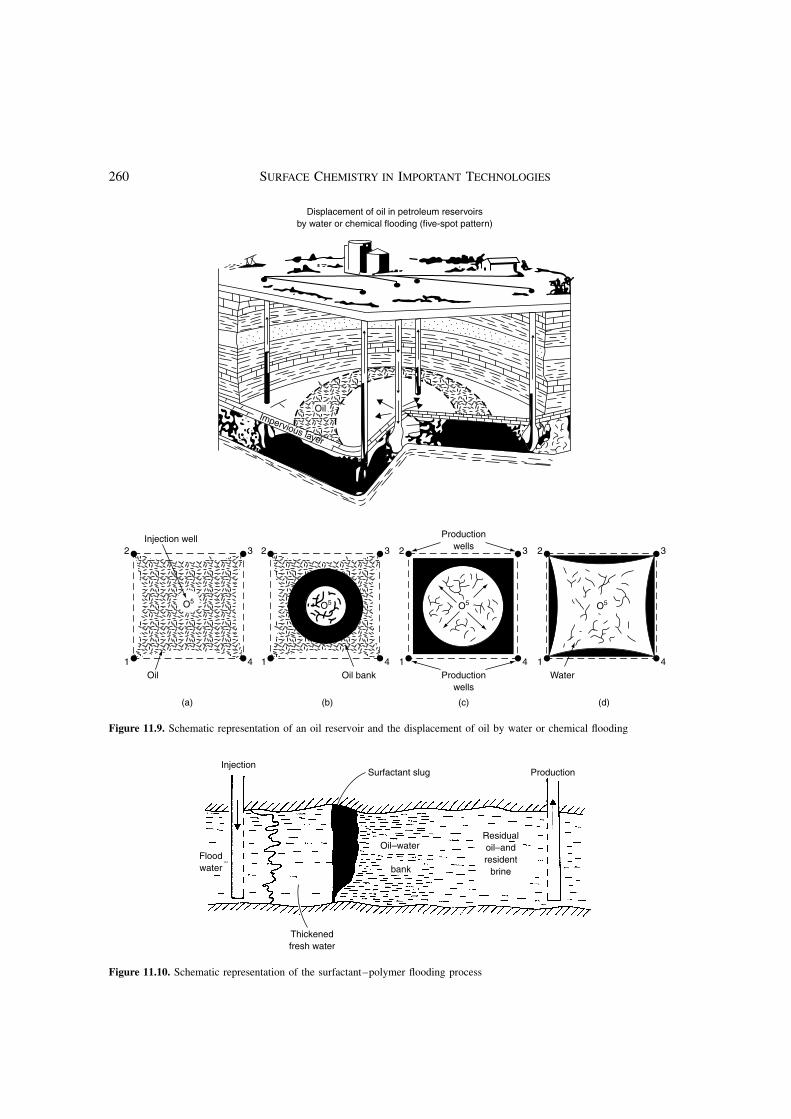
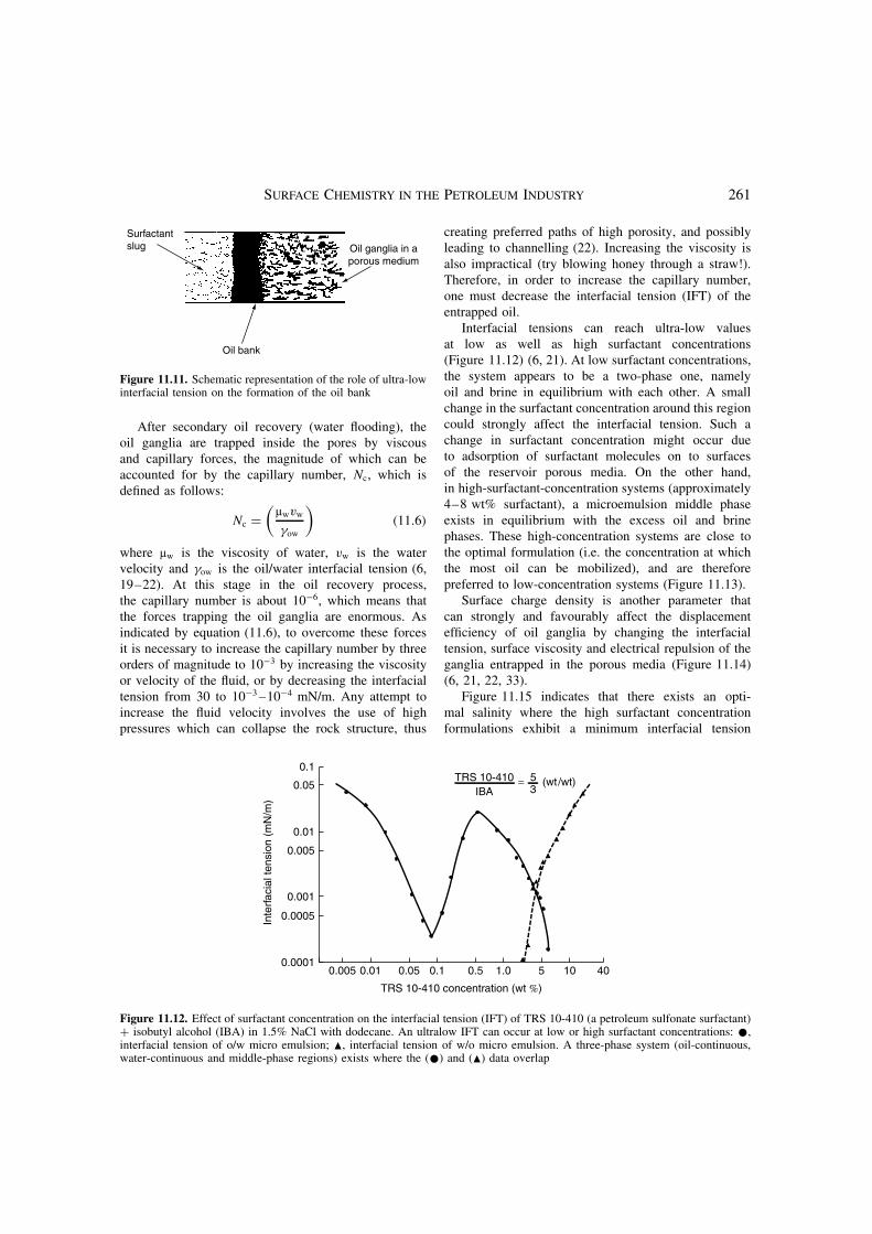
This present section will deal in a general way with allof those technologies referred to as “surfactant–polymerflooding” or “chemical flooding”. Basically, the purposeof surfactant–polymer flooding is to produce oil from anexhausted petroleum well by injecting into the reservoira slug of surface-active agents capable of mobilizingthe residual oil (Figure 11.9) (6, 19–22). Figure 11.10shows schematically the surfactant–polymer floodingprocess. The first step is to inject a solution (preflush) tocondition the reservoir by eliminating undesirable saltsthat would otherwise bind to the valuable surfactants andrender them ineffective (20, 23–26). Next, a surfactantsolution is injected to decrease the interfacial tensionof the oil ganglia (6, 19–22, 27), and to mobilize theganglia through narrow necks of the pores (6, 21),thus forming an oil bank (as shown in Figure 11.11).The formation of an oil bank is indispensable, sinceit will allow the efficient mobilization of the trappedcrude oil. The surfactant slug is driven by a slugof thickened aqueous polymer solution that is in turndriven by a water slug (6, 20, 21). The viscous polymerslug prevents fingers of water from penetrating the oilbank, which would otherwise make the process lesseffective (22).
In order to optimize the surfactant–polymer floodingprocess, the oil bank formed must be propagated throughthe porous media while the oil ganglia continue tocoalesce with the leading edge of the oil bank. Thevolumetric coverage of the process is optimized byadjusting the mobility of each slug (Figure 11.11) (6,22). This is accomplished by maintaining the ultra-low interfacial tension at the oil bank/surfactant sluginterface (6, 28).
There also exists a need to avoid surfactant aggregatestructures such as lamellar liquid crystals which exhibithigh viscosity (29–32). System parameters should besuch that mixing between the fluids in the surfactant,oil and polymer slugs does not occur. A dispersion ofsurfactant and oil would form an undesired emulsion,while a dispersion of surfactant and polymer, if incom-patible, could lead to phase separation, which woulddecrease the effectiveness of the process. Other pointsto take into account are (i) the mass transfer of surfac-tant to the oil bank can change the interfacial tension,and (ii) surfactant–polymer incompatibility leads to aphase separation, which would reduce the efficiency ofthe process (30, 31).
260 SURFACE CHEMISTRY IN IMPORTANT TECHNOLOGIES
1 4
2 3
1 4
2 3
1 4
2 3
1 4
2 3Injection well
Oil Oil bank WaterProductionwells
(c) (d)(a) (b)
Productionwells
Displacement of oil in petroleum reservoirsby water or chemical flooding (five-spot pattern)
O5 O5 O5 O5
Impervious layer
Oil
Figure 11.9. Schematic representation of an oil reservoir and the displacement of oil by water or chemical flooding
Thickenedfresh water
Oil–water
bank
Residualoil–andresident
brine
Surfactant slug ProductionInjection
Floodwater
Figure 11.10. Schematic representation of the surfactant–polymer flooding process
SURFACE CHEMISTRY IN THE PETROLEUM INDUSTRY 261
Surfactantslug
Oil bank
Oil ganglia in aporous medium
Figure 11.11. Schematic representation of the role of ultra-lowinterfacial tension on the formation of the oil bank
After secondary oil recovery (water flooding), theoil ganglia are trapped inside the pores by viscousand capillary forces, the magnitude of which can beaccounted for by the capillary number, Nc, which isdefined as follows:
Nc =(
µwvw
γow
)(11.6)
where µw is the viscosity of water, vw is the watervelocity and γow is the oil/water interfacial tension (6,19–22). At this stage in the oil recovery process,the capillary number is about 10−6, which means thatthe forces trapping the oil ganglia are enormous. Asindicated by equation (11.6), to overcome these forcesit is necessary to increase the capillary number by threeorders of magnitude to 10−3 by increasing the viscosityor velocity of the fluid, or by decreasing the interfacialtension from 30 to 10−3 –10−4 mN/m. Any attempt toincrease the fluid velocity involves the use of highpressures which can collapse the rock structure, thus
creating preferred paths of high porosity, and possiblyleading to channelling (22). Increasing the viscosity isalso impractical (try blowing honey through a straw!).Therefore, in order to increase the capillary number,one must decrease the interfacial tension (IFT) of theentrapped oil.
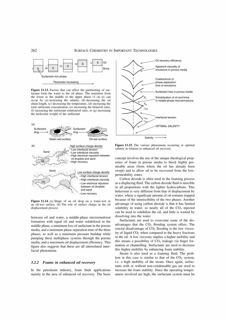
Interfacial tensions can reach ultra-low valuesat low as well as high surfactant concentrations(Figure 11.12) (6, 21). At low surfactant concentrations,the system appears to be a two-phase one, namelyoil and brine in equilibrium with each other. A smallchange in the surfactant concentration around this regioncould strongly affect the interfacial tension. Such achange in surfactant concentration might occur dueto adsorption of surfactant molecules on to surfacesof the reservoir porous media. On the other hand,in high-surfactant-concentration systems (approximately4–8 wt% surfactant), a microemulsion middle phaseexists in equilibrium with the excess oil and brinephases. These high-concentration systems are close tothe optimal formulation (i.e. the concentration at whichthe most oil can be mobilized), and are thereforepreferred to low-concentration systems (Figure 11.13).
Surface charge density is another parameter thatcan strongly and favourably affect the displacementefficiency of oil ganglia by changing the interfacialtension, surface viscosity and electrical repulsion of theganglia entrapped in the porous media (Figure 11.14)(6, 21, 22, 33).
Figure 11.15 indicates that there exists an opti-mal salinity where the high surfactant concentrationformulations exhibit a minimum interfacial tension
0.1
0.05
0.01
0.005
Inte
rfac
ial t
ensi
on (
mN
/m)
0.001
0.0005
0.00010.005 0.05 0.5 1.0 5 10 400.1
TRS 10-410 concentration (wt %)
0.01
TRS 10-410IBA
= 5 (wt/wt) 3
Figure 11.12. Effect of surfactant concentration on the interfacial tension (IFT) of TRS 10-410 (a petroleum sulfonate surfactant)+ isobutyl alcohol (IBA) in 1.5% NaCl with dodecane. An ultralow IFT can occur at low or high surfactant concentrations: •,interfacial tension of o/w micro emulsion; �, interfacial tension of w/o micro emulsion. A three-phase system (oil-continuous,water-continuous and middle-phase regions) exists where the (•) and (�) data overlap
262 SURFACE CHEMISTRY IN IMPORTANT TECHNOLOGIES
S
Surfactant-rich phase
Parameter increasing
l mm
m u
SS
S S Oil
Brine
Figure 11.13. Factors that can affect the partitioning of sur-factant from the water to the oil phase. The transition fromthe lower to the middle to the upper phase (1–m–u) canoccur by (a) increasing the salinity, (b) decreasing the oilchain length, (c) decreasing the temperature, (d) increasing thetotal surfactant concentration, (e) increasing the brine/oil ratio,(f) increasing the surfactant solution/oil ratio, or (g) increasingthe molecular weight of the surfactant
Surfactantslug
Surfactantslug
Water-wet surface
Sand
Sand
Oil
Oil
Oil-wet surface
–Low interfacial tension–Low interfacial viscosity–High electrical repulsion between oil droplets and sand–High recovery
High surface charge density
–High interfacial tension–High interfacial viscosity–Low electrical repulsion between oil droplets and sand–Low recovery
Low surface charge density
(a)
(b)
Figure 11.14. (a) Shape of an oil drop on a water-wet oran oil-wet surface. (b) The role of surface charge in the oildisplacement process
between oil and water, a middle-phase microemulsionformation with equal oil and water solubilized in themiddle phase, a minimum loss of surfactant in the porousmedia, and a minimum phase separation time of the threephases, as well as a minimum pressure buildup whilepumping these multiphase systems through the porousmedia, and a maximum oil displacement efficiency. Thisfigure also suggests that these are all interrelated inter-facial phenomena.
3.2.2 Foams in enhanced oil recovery
In the petroleum industry, foam finds applicationsmainly in the area of enhanced oil recovery. The basic
Oil recovery efficiency
Apparent viscosity ofemulsions in porous media
Coalescence orphase-separationtime of emulsions
Surfactant loss in porous media
Solubilization of oil and brinein middle-phase microemulsions
Interfacial tension
OPTIMAL SALINITY
Salinity
Vo
Vw
gmw
gmogow
Figure 11.15. The various phenomena occurring at optimalsalinity in relation to enhanced oil recovery
concept involves the use of the unique rheological prop-erties of foam in porous media to block highly per-meable areas (from where the oil has already beenswept) and to allow oil to be recovered from the low-permeability zones.
Carbon dioxide is often used in the foaming processas a displacing fluid. The carbon dioxide fluid is misciblein all proportions with the lighter hydrocarbons. Thisbehaviour is very different from that of displacement bywater, where a significant amount of oil remains trappedbecause of the immiscibility of the two phases. Anotheradvantage of using carbon dioxide is that it has limitedsolubility in water, so nearly all of the CO2 injectedcan be used to solubilize the oil, and little is wasted bydissolving into the water.
Surfactants are used to overcome some of the dis-advantages that the CO2 flooding system offers. Thecrucial disadvantage of CO2 flooding is the low viscos-ity of liquid CO2 when compared to the heavy fractionsin the oil. A low viscosity implies a higher mobility andthis means a possibility of CO2 leakage via finger for-mation or channelling. Surfactants are used to decreasethis higher mobility by enhancing foam stability.
Steam is also used as a foaming fluid. The prob-lem in this case is similar to that of the CO2 system,i.e. a high mobility of the steam. Once again, surfac-tants with or without non-condensable gas are used toincrease the foam stability. Since the operating temper-atures involved are high, the surfactant system must be

SURFACE CHEMISTRY IN THE PETROLEUM INDUSTRY 263
designed to remain effective over a wide range of tem-peratures. The adsorption of surfactants on to reservoirrock surfaces is minimal at high temperatures, unlessionic species are present. If the foam is made outof “pure” steam (saturated steam in equilibrium withwater as the lamella), according to Kelvin’s equation,the smaller bubbles, which have a higher pressure, willcollapse and be absorbed by larger bubbles, thus result-ing in decreased foam stability. Small amounts of non-condensable gas are added to increase the foam stabilityby decreasing the rate of steam condensation and foamcollapse.
The text by Schramm (34) covers most aspects ofthe use of foams in the petroleum industry, rangingfrom fundamentals to enhanced oil recovery. It alsoprovides field data from several oil fields along withthe “in-laboratory” experimental methods that are usedto correlate field data to proposed theories.
3.2.3 Acid fracturing for oil well stimulation
Acid fracturing is an oil well stimulation process inwhich acid (HCl or HF, depending on the rock structure)is injected into an oil well at sufficiently high pressureto fracture the porous media or to widen existing naturalfractures. Various principles of surface chemistry areemployed in this process in order to avoid excessiveand costly fluid loss, and to decrease the rate of acidspent.
For controlling fluid loss, surfactants are used asthickeners which gel the acid by forming micelles.These gelled acids are shear-stable because micellarchains can quickly reform following shearing. Theadvantages of surfactants as thickeners is that they canbe designed to provide high viscosity to “live” (i.e.active) acid solutions, while at the same time providinglow viscosity to the spent acid. This is possible becauseof the disruption of the micellar structure due to theincreased concentration of reaction products formedduring spending of acid. The decreased spent acidviscosity aids in recovery of the treating fluids (35).
The employment of foamed acid and acid-externalemulsions (oil as the dispersed phase and gelled acid asthe continuous phase) are other methods used to controlthe loss of acid solutions. The disadvantage of using oilsis that a large concentration of oil is required to increasethe viscosity of the emulsion formulation, which reducesthe acid concentration and, therefore, the amount of acidavailable for fracture etching. Foaming the acid alsoreduces the amount of acid available for etching sinceless acid is present per unit volume injected.
To control the reaction rate of the acid, retarderssuch as alkyl sulfonates, alkyl phosphonates and alkylamines are used to form hydrophobic films on carbonatesurfaces. These protective films act as a barrier to slowacid attack. Another method involves the use of foamingagents to stabilize the carbon dioxide foam that iscreated when CO2 is released as a product of the acid-etching reaction. This CO2 foam acts as a barrier to slowacid attack. Yet another method for controlling the acidactivity in an oil well is the use of emulsions containingkerosene or diesel as the continuous oil phase andhydrochloric acid as the dispersed aqueous phase. Acid-in-oil emulsions are most commonly used because oilseparates the acid from the carbonate surface (and frommachine parts, thus reducing the level of corrosion).Moreover, acid reaction rates can be further decreasedby surfactant retarders that increase the wettability ofthe carbonate surface for oil.
3.3 Antifoaming and defoaming
Foam shows peculiar properties that are useful inenhanced oil recovery. However, foam turns out to bea major problem in all downstream processing of therecovered crude oil. The causes of foaming are usuallyrelated to naturally occurring impurities and corrosionproducts found in process streams. Antifoaming anddefoaming agents are added in all major unit operationsto avoid foaming. Antifoaming agents are added toprevent the formation of new foam, while defoamers areadded to destroy the existing foam (34). Hydrophobicsilicas, silicone oils, glycol-based polymers, amides,mineral oils and fatty acids are common antifoamingagents (34).
3.4 Corrosion inhibition
The petroleum industry does not remain unaffectedby corrosion (as was alluded to in the discussion onacid-in-oil emulsions above). Indeed, corrosion is acommon phenomenon endured by almost every industry.The metallic parts used everywhere from oil wells torefineries and petrochemical plants are susceptible tocorrosion. In 1999, in the USA alone, corrosion washeld responsible for approximately $300 billion of lostrevenue, of which more than one third could havebeen saved by using available methods of corrosioncontrol (36).
264 SURFACE CHEMISTRY IN IMPORTANT TECHNOLOGIES
H+H+
H+H+
H+ H+ H+ H+ H+ H+ H+
Filmformationdue tocationicsurfactant
(a) (b)
Metal Metal
+ + ++ + + +
H+
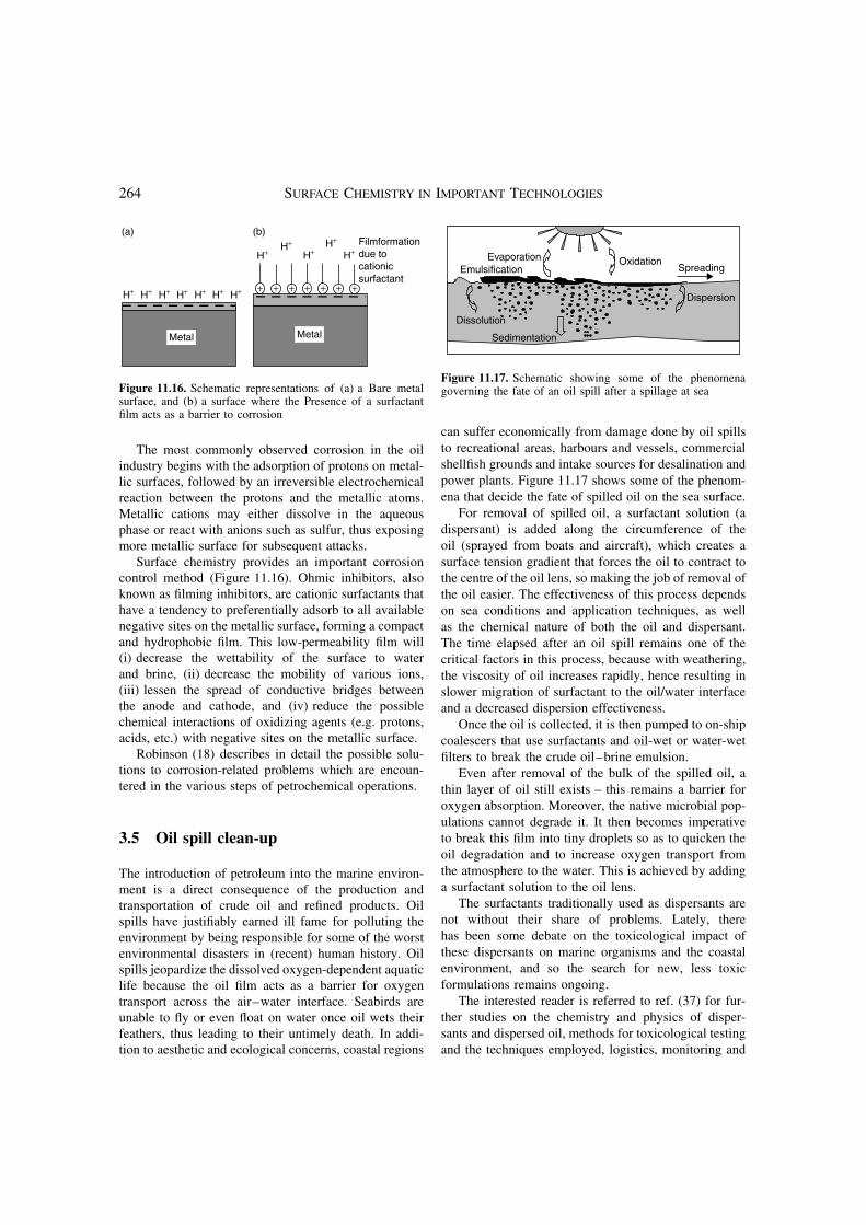
Figure 11.16. Schematic representations of (a) a Bare metalsurface, and (b) a surface where the Presence of a surfactantfilm acts as a barrier to corrosion
The most commonly observed corrosion in the oilindustry begins with the adsorption of protons on metal-lic surfaces, followed by an irreversible electrochemicalreaction between the protons and the metallic atoms.Metallic cations may either dissolve in the aqueousphase or react with anions such as sulfur, thus exposingmore metallic surface for subsequent attacks.
Surface chemistry provides an important corrosioncontrol method (Figure 11.16). Ohmic inhibitors, alsoknown as filming inhibitors, are cationic surfactants thathave a tendency to preferentially adsorb to all availablenegative sites on the metallic surface, forming a compactand hydrophobic film. This low-permeability film will(i) decrease the wettability of the surface to waterand brine, (ii) decrease the mobility of various ions,(iii) lessen the spread of conductive bridges betweenthe anode and cathode, and (iv) reduce the possiblechemical interactions of oxidizing agents (e.g. protons,acids, etc.) with negative sites on the metallic surface.
Robinson (18) describes in detail the possible solu-tions to corrosion-related problems which are encoun-tered in the various steps of petrochemical operations.
3.5 Oil spill clean-up
The introduction of petroleum into the marine environ-ment is a direct consequence of the production andtransportation of crude oil and refined products. Oilspills have justifiably earned ill fame for polluting theenvironment by being responsible for some of the worstenvironmental disasters in (recent) human history. Oilspills jeopardize the dissolved oxygen-dependent aquaticlife because the oil film acts as a barrier for oxygentransport across the air–water interface. Seabirds areunable to fly or even float on water once oil wets theirfeathers, thus leading to their untimely death. In addi-tion to aesthetic and ecological concerns, coastal regions
SpreadingEmulsificationEvaporation
Dissolution
Sedimentation
Dispersion
Oxidation
Figure 11.17. Schematic showing some of the phenomenagoverning the fate of an oil spill after a spillage at sea
can suffer economically from damage done by oil spillsto recreational areas, harbours and vessels, commercialshellfish grounds and intake sources for desalination andpower plants. Figure 11.17 shows some of the phenom-ena that decide the fate of spilled oil on the sea surface.
For removal of spilled oil, a surfactant solution (adispersant) is added along the circumference of theoil (sprayed from boats and aircraft), which creates asurface tension gradient that forces the oil to contract tothe centre of the oil lens, so making the job of removal ofthe oil easier. The effectiveness of this process dependson sea conditions and application techniques, as wellas the chemical nature of both the oil and dispersant.The time elapsed after an oil spill remains one of thecritical factors in this process, because with weathering,the viscosity of oil increases rapidly, hence resulting inslower migration of surfactant to the oil/water interfaceand a decreased dispersion effectiveness.
Once the oil is collected, it is then pumped to on-shipcoalescers that use surfactants and oil-wet or water-wetfilters to break the crude oil–brine emulsion.
Even after removal of the bulk of the spilled oil, athin layer of oil still exists – this remains a barrier foroxygen absorption. Moreover, the native microbial pop-ulations cannot degrade it. It then becomes imperativeto break this film into tiny droplets so as to quicken theoil degradation and to increase oxygen transport fromthe atmosphere to the water. This is achieved by addinga surfactant solution to the oil lens.
The surfactants traditionally used as dispersants arenot without their share of problems. Lately, therehas been some debate on the toxicological impact ofthese dispersants on marine organisms and the coastalenvironment, and so the search for new, less toxicformulations remains ongoing.
The interested reader is referred to ref. (37) for fur-ther studies on the chemistry and physics of disper-sants and dispersed oil, methods for toxicological testingand the techniques employed, logistics, monitoring and
SURFACE CHEMISTRY IN THE PETROLEUM INDUSTRY 265
application strategies for using various dispersants in theUnited States.
3.6 Fluidization of bitumen
Bitumen is a naturally occurring hydrocarbon that existsin a semi-solid or solid phase in natural deposits. Themost important reservoirs of bitumen are found inCanada and Venezuela. Among the problems encoun-tered when recovering bitumen, its high viscosity is oneof the greatest. Natural bitumen has a viscosity greaterthan 10 000 mPa, measured on a gas-free basis at itsoriginal temperature in the deposit and atmospheric pres-sure (38, 39).
Current technology has made possible the recoveryand use of this huge source of energy (38–41). More-over, since the extraction process of this raw materialrequires much less energy than the refining processrequired for other fossil fuels, (the bitumen extractionindustry is flourishing.) Gas-oil, which is an intermedi-ate product created during the refining of crude oil, ispumped into the oil well to reduce the viscosity of thebitumen and allow it to be pumped from undergroundto a flow station (at ground level.)
A commercial product known as Orimulsion isan example of the application of surface chemistryto the technology of conferring special properties toheavy crude oil1. This is an oil-in-water emulsion madefrom bitumen stabilized by a nonionic surfactant, whichdecreases the viscosity of the bitumen from 105 to lessthan 102 mPa, and reduces the NOx emissions while stillmaintaining a high combustion performance (42).
It is worth mentioning here that to optimize the lowviscosity of an emulsion, two emulsions of different dropsize distributions are mixed, with the smaller one beingabout 25% and the larger one about 75% of the totalconcentration (43).
3.7 Asphaltic emulsions
Another very important application of surface science inthe petroleum industry that has recently been receivingmuch attention is the creation of oil-in-water asphalticemulsions (asphalt dispersed in a brine continuousphase) which are used to pave roads (44). The idea isto decrease the viscosity of asphalt, while at the sametime avoiding the use of gasoline. The latter is presently
1 Note: Orimulsion is a trademark of INTEVEP, SA, a branchcompany of Petroleos de Venezuela, SA (PDVSA).
being used to fluidize asphalt, but has high economicand environmental costs.
For this technological application, the main types ofsurfactants used have been cationics, since most rocksurfaces are negatively charged. By using this method,when the asphaltic emulsion contacts the ground, surfac-tant molecules migrate from the surface of the asphaltdroplets to the rock surfaces, which results in the break-ing of the asphaltic emulsion and a permanent spreadof asphalt on to the rock surfaces. Cationic surfactantsare preferred, despite their high cost, because they pro-mote faster breakup of the asphalt emulsion, which isoften necessary to prevent the possibility of rain wash-ing away the asphalt before it has solidified. However,work is currently being carried out to incorporate non-ionic surfactants into the emulsion in order to reducecosts and to improve the mechanical properties of theasphalt.
3.8 Oil/water separation and crude oildehydration
Oil-water emulsion systems are often desirable in casessuch as the transportation of crude oil and increased fuelefficiency of light oil fractions. By the same token, thesesystems are undesirable for distillation and catalyticcracking of crude oil. More than 50% of all of thepetroleum recovered is in the form of water-in-oilemulsions. These emulsions are formed because crudeoil contains natural surfactants and the oil and water areemulsified as they pass through mechanical devices suchas pumps or valves. Water must be removed before anyrefinery operation can be performed on this oil material.It is not economically viable to distill crude oil inemulsion form because of the incremental energy coststhat would be encountered when producing fractionsin the established standard viscosity range. Moreover,water may poison or reduce the activities of the catalystsused in catalytic cracking processes further down theprocessing line.
In earlier days, the method used to destabilize a crudeoil/water emulsion was gravity-heating sedimentation.Nowadays, however, chemical de-emulsification andimproved electromagnetic and gravitational techniquesare the main methods used to break down an emulsion.
Such methods take advantage of inexpensive de-emulsifying chemicals to enable the collision and fusionof droplets that ultimately lead to oil/water phase sepa-ration. This is achieved by adjusting the surface chargedensity, counterion concentration and temperature. Poly-mers are also added to promote flocculation. A detailed
266 SURFACE CHEMISTRY IN IMPORTANT TECHNOLOGIES
discussion of the electrostatic phenomena used in thisprocess can be found in ref. (45).
The coagulants (typically multivalent counterions)commonly used are the salts of aluminium and ironand salts or the bases of calcium and magnesium. Thetransition from stabilized to destabilized emulsions onchanging the temperature is very sharp at the criticalflocculation temperature (CFT) when nonionic surfac-tants are used. Generally, aqueous dispersions desta-bilize upon increasing temperature, while non-aqueousdispersions destabilize with decreasing temperature.
To dissolve the stabilizing agent, the use of cosol-vents such as carbon disulfide, carbon tetrachloride,acetone and ether is in current practice. For specificexamples of oil/water separations and for further detailsabout the use of dissolved air floatation, deep bed filtra-tion, and the selection and sizing of various equipment,the interested reader is referred to ref. (46).
4 SUMMARY
Surfactants have very special qualities that make theminvaluable to the petroleum industry. The relevance ofvarious interfacial phenomena, such as adsorbed surfac-tant films, self-assembly, contact angle, wetting, foamsand emulsions, in nearly every process in the industryhas been discussed. In addition, this chapter summa-rized the importance of the adsorption and aggrega-tion behaviour of surfactants with regard to drilling,enhanced oil recovery, antifoaming, corrosion inhibition,oil spill clean-up, oil/water separation and fluidization ofhighly viscous materials.
5 REFERENCES
1. Shah, D. O., The world of surface science, in Chemi-cal Engineering Education , Anderson, T. J. (Ed.), Amer-ican Society for Engineering Education, Winter 1977,pp. 14–48.
2. Gary, J. H. and Handwerk, G. E., Petroleum Refining:Technology and Economics , 3rd Edn, Marcel Dekker, NewYork, 1994.
3. Gibbs, J. W., The Collected Works of J. W. Gibbs, Vol. I,Longmans & Green, New York, 1931.
4. Guggenheim, E. A. and Adam, N. K., The thermodynam-ics of adsorption at the surface of solutions Proc. R. Soc.London, A, 139, 218–236 (1933).
5. Adamson, A. W. and Gast, A. P., Physical Chemistry ofSurfaces , 6th Edn, Wiley, New York, 1997.
6. Shah, D. O., Fundamental aspects of surfactant–polymerflooding process, Keynote paper presented at the European
Symposium on Enhanced Oil Recovery , Bournemouth, UK,September 21–23, 1981, Elsevier, Lausanne, Switzerland,1981.
7. Patist, A., Jha, B. K., Oh, S. -G. and Shah, D. O., Impor-tance of micellar relaxation time on detergent properties.J. Surfoctants Deterg., 2, 317–324 (1999).
8. Davies, J. T. and Rideal, E. K., Interfacial Phenomena ,2nd Edn, Academic Press, New York, 1963.
9. Myers, D., Surfaces, Interfaces, and Colloids: Principlesand Applications , 2nd Edn, Wiley-VCH, New York, 1999.
10. Battelle, Testing and Characterization of Orimulsion-400 , Volume 1 – Technical Report, Battelle MemorialInstitute, Duxbury, MA, 1998.
11. Salager, J. L., Phase inversion and emulsion inversionon the basics of catastrophe theory, in Encyclopedia ofEmulsion Technology , Vol. 3, Becher, P. (Ed.), MarcelDekker, New York, 1983, pp. 79– 134.
12. Griffin, W. C., Classification of surface active agents by“HLB”, J. Soc. Cosmet. Chem., 1, 311–326 (1949); Grif-fin, W. C., Calculation of HLB values of non-ionic surfac-tants J. Soc. Cosmet. Chem., 5, 249–256 (1954).
13. Bancroft, W. D., The theory of emulsification V, J. Phys.Chem., 17, 501–519 (1913); Bancroft, W. D., The theoryof emulsification VI, J. Phys. Chem., 19, 275–309 (1915).
14. Becher, P., HLB – A survey, in Surfactants in Solu-tion , Vol. 3, Mittal, K. L., (Ed.), Plenum, New York,1984 pp. 1925–1946; Becher, P., Hydrophile–lipophilebalance-History and recent developments (Langmuir Lec-ture, 1983), J. Disper. Sci. Technol., 5, 81–96 (1984).
15. Winsor, P. A., Solvent Properties of Amphiphilic Com-pounds , Butterworth, London, 1954.
16. Shinoda, K. and Arai, H., The correlation between phaseinversion temperature in emulsion and cloud point in solu-tion of nonionic emulsifier, J. Phys. Chem., 68, 3485–3490(1964).
17. Ruckenstein, E. and Chi, J. C., Stability of microemul-sions, J. Chem. Soc., Faraday Trans. 2 , 71, 1690–1707(1975).
18. Robinson, J. S., Corrosion Inhibitors – Recent Develop-ments , Noyes Data Corporation, Park Ridge, NJ, 1979.
19. Rivas H., Gutierrez, X., Ziritt, J. L., Anton, R. E. andSalager, J. L., Microemulsion and optimal formulationoccurrence in pH-dependent systems as found inalkaline-enhanced oil recovery, in Industrial Applicationsof Microemulsions , Solans, C. and Kunieda, H. (Eds),Surfactant Science Series, Vol. 66, Marcel Dekker, NewYork, 1997, pp. 305–329.
20. Baviere, M. and Canselier, J. P., Microemulsion in thechemical EOR process, in Industrial Applications ofMicroemulsions , Solans, C. and Kunieda, H. (Eds), Sur-factant Science Series, Vol. 66, Marcel Dekker, New York,1997, pp. 331–353.
21. Pillai, V., Kanicky, J. R. and Shah, D. O., Applications ofmicroemulsions in enhanced oil recovery, in Handbookof Microemulsion Science and Technology , Kumar P. andMittal, K. L. (Eds), Marcel Dekker, New York, 1999,pp. 743–753.
SURFACE CHEMISTRY IN THE PETROLEUM INDUSTRY 267
22. Willson, Jr, L. A., Physicochemical environment ofpetroleum reservoirs in relation to oil recovery systems, inImproved Oil Recovery by Surfactant and Polymer Flood-ing , Shah, D. O. and Schechter, R. S. (Eds), AcademicPress, New York, 1977, pp. 1–26.
23. Somasundaran, P. and Hanna, H. S., Physico-chemicalaspects of adsorption at solid/liquid interfaces. I. Basicprinciples, in Improved Oil Recovery by Surfactant andPolymer Flooding , Shah, D. O. and Schechter, R. S. (Eds),Academic Press, New York, 1977, pp. 205–251.
24. Hanna, H. S. and Somasundaran, P., Physico-chemicalaspects of adsorption at solid/liquid interfaces. II. Maho-gany sulfonate/berea sandstone, kaolinite, in ImprovedOil Recovery by Surfactant and Polymer Flooding ,Shah, D. O. and Schechter, R. S. (Eds), Academic Press,New York, 1977, pp. 253–274.
25. Malmberg, E. W. and Smith, L., The adsorption losses ofsurfactants in tertiary recovery systems, in Improved OilRecovery by Surfactant and Polymer Flooding , Shah, D. O.and Schechter, R. S. (Eds), Academic Press, New York,1977, pp. 275–291.
26. Willhite, G. P. and Dominguez, J. G., Mechanisms ofpolymer retention in porous media, in Improved Oil Recov-ery by Surfactant and Polymer Flooding , Shah, D. O.and Schechter, R. S., Academic Press, New York, 1977,pp. 511–554.
27. Morgan, J. C., Schechter, R. S. and Wade, W. H., Recentadvances in the study of low interfacial tensions, inImproved Oil Recovery by Surfactant and Polymer Flood-ing , Shah, D. O. and Schechter, R. S., Academic Press,New York, 1977, pp. 101–118.
28. Stegemeier, G. L., Mechanisms of entrapment and mobi-lization of oil in porous media, in Improved Oil Recov-ery by Surfactant and Polymer Flooding Shah, D. O.and Schechter, R. S., Academic Press, New York, 1977,pp. 55–91.
29. Mashiko, A. B. E., Microemulsions in enhanced oil recov-ery: Middle-phase microemulsion formation with sometypical anionic surfactants, in Industrial Applications ofMicroemulsions , Solans, C. and Kunieda, H. (Eds), Sur-factant Science Series, Vol. 66, Marcel Dekker, New York,1997, pp. 279–303.
30. Lissant, K. J., Emulsification and demulsification in oilrecovery, in Improved Oil Recovery by Surfactant andPolymer Flooding , Shah, D. O. and Schechter, R. S. (Eds),Academic Press, New York, 1977, pp. 93–100.
31. Shah, D. O., Bansal, V. K., Chan, K. S. and Hsieh, W. C.,The structure, formation, and phase inversion ofmicroemulsions, in Improved Oil Recovery by Sur-factant and Polymer Flooding , Shah, D. O. and Schechter,R. S. (Eds), Academic Press, New York, 1977,pp. 293–337.
32. Metzner, A. B., Flows of polymeric solution and emul-sions through porous media: Current status, in ImprovedOil Recovery by Surfactant and Polymer Flooding ,Shah, D. O. and Schechter, R. S. (Eds), Academic Press,New York, 1977, pp. 439–451.
33. Wasan, D. T. and Mohan, V., Interfacial rheological prop-erties of fluid interfaces containing surfactants, in ImprovedOil Recovery by Surfactant and Polymer Flooding ,Shah, D. O. and Schechter, R. S. (Eds), Academic Press,New York, 1977, pp. 161–203.
34. Schramm, L. L. (Ed.), Foams: Fundamentals and Appli-cations in the Petroleum Industry , Advances in ChemistryServices, Vol. 242, American Chemical Society, Washing-ton, DC, 1994.
35. Economides, M. J. and Nolte, K. G., Reservoir Stimula-tion , Prentice Hall, Englewood Cliffs, NJ, 1989.
36. Davis, J. R. (Ed.), Corrosion: Understanding the Basics ,ASM International, Materials Park, OH, 2000.
37. Committee on Effectiveness of Oil Spill Dispersants,Report of the Marine Board Commission on Engineer-ing and Technical Solutions , National Research Council,National Academy Press, Washington, DC, 1989.
38. Miller, C. A., Linak, W. P., King, C. and Wendt, J. O. L.,Fine particle emissions from heavy fuel oil combustionin a firetube package boiler, Combust. Sci. Technol. 134,477–502 (1998).
39. Miller, C. A. and Srivastava, R. K., The combustion ofOrimulsion and its generation of air pollutants, Prog.Energy Combust. Sci., 26 131–160 (2000).
40. Rivas, H. and Colmenares, T., ORIMULSION: Newgenerations and future perspectives, Vis. Tecnol. (SpecialIssue), 49–60, (1999).
41. Anon, Dalhousie Orimulsion conversion and scrubberfacility wins 1995 Powerplant of the Year Award, Power ,139, 27–32 (1995).
42. Zaki, M. I., Nael, N., Ahmed, N. S. and Nassar, A. M.,Sodium lignin sulfonate to stabilize heavy crude oil-in-water emulsions for pipeline transportation, Petrol. Sci.Technol., 18, 1175–1193 (2000).
43. Nunez, G. A., Sanchez, G., Gutierrez, X., Silva, F.,Dalas, C. and Rivas, H., Rheological behavior ofconcentrated bitumen in water emulsions, Langmuir , 16,6497–6502 (2000).
44. Puzinauskas, V. P. and Jester, R. N., Design of emulsifiedasphalt paving mixtures, National Cooperative HighwayResearch Program Report 259, Transportation ResearchBoard, Washington, DC, 1983.
45. Hunter, R. J. and White, L. R., Foundations of ColloidScience, Oxford University Press, New York, 1987.
46. Wasan, D. T., Ginn, M. E. and Shah, D. O., Surfactantsin Chemical/Process Engineering , Marcel Dekker, NewYork, 1998.