chapter 11 construction surveys - virginia
TRANSCRIPT

CHAPTER 11
CONSTRUCTION SURVEYS
Chapter Contents
Sec. 11.01 General Sec. 11.02 Alignment Sec. 11.03 Levels, Benchmarks & Project Elevations Sec. 11.04 DTMs Sec. 11.05 Borrow Pits Sec. 11.06 Culvert Stakeout Sec. 11.07 Bridge Stakeout Sec. 11.08 Slope Stakes Sec. 11.09 Fine Grade Stakes Sec. 11.10 Right of Way Stakes Sec. 11.11 Federal and Non-Federal Aid State Force Account
Projects Sec. 11.12 No Plan Projects Sec. 11.13 Minimum Plan Projects Sec. 11.14 Condemnation Staking Sec. 11.15 As-built Plan of Right of Way Monumentation Sec. 11.16 Submitting Survey Data Figures 11-A-D Alignment Staking (Field Notes) Figures 11-E-G Level & Slope Staking (Field Notes) Figure 11-H Benchmark Leveling (Field Notes) Figure 11-I Various Stake Markings Figure 11-J Bridge Stake-Out Sketch Figure 11-K Slope Staking on Tangents and Curves Figure 11-L Checking a Box Culvert Figure 11-1 Culvert Staking Figure 11-2-3 Bridge Staking Figure 11-4-5 Right of Way Staking

11-1
Sec. 11.01 General
Construction surveys shall be made in accordance with Section 105.13 (State Force Construction Surveying) & Section 517 (Contractor Construction Surveying) of the VDOT Road and Bridge Specifications and the applicable provisions for construction surveying described within the VDOT Construction Manual.
The Contract Surveyor or Survey Manager (whichever is performing the stakeout) should
become familiar with the project plans and specifications, VDOT Road and Bridge Specifications, VDOT Construction Manual and contract prior to the Pre-Construction Conference so any concerns can be addressed at that meeting. All points staked must be recorded with a 10k additive to the staked point number and downloaded to a staked .dgn file which is stored in ProjectWise.
Unless specifically instructed by the District Survey Manager, the Department Survey
Crew is not to perform checks on any survey work performed by the contractor.
Sec. 11.02 Alignment The construction centerline shall be established using the alignment data sheet and the established coordinate values that are included in the plan set. All control points used during construction stakeout should be referenced and recorded for future use. Any discrepancies in the construction alignment should be brought to the immediate attention of the project inspector.
All notes relative to the retracing of the plan alignment shall be recorded in the digital file, ASCII file, or field book in the standard manner, and should be retained by the survey party for the use of retracing the line after construction, if needed (Figures 11-B through 11-D). For marking centerline and reference stakes, please see Figure 11-I. Sec. 11.03 Levels, Benchmarks and Project Elevations
Project benchmarks are shown on the alignment data sheet in the plan set. These benchmarks should be checked for description, position and elevation prior to their use in stakeout. Differential leveling should be run between the plan benchmarks and recorded in field notes. Any appreciable differences in benchmark elevation should be recorded in field notes and check levels should be run to verify the difference. The project inspector should be notified of the discrepancies so they can notify the Survey Manager. If additional benchmarks are set on the project, a list of these benchmarks with a description, position and elevation should be given to the project inspector and contractor. For examples of level notes see Figures 11E through 11G, and Figure 11H.

11-2
Sec. 11.04 DTMs DTMs will not be required on plan quantity projects. Of the majority of projects currently
designed, regular excavation is plan quantity. For those projects that are designed as non-plan quantity, then original ground DTMs will need to be secured during the slope stake process. These will be done so accurate excavation quantities can be computed for the project. In these rare instances, the Survey Manager can be contacted for proper procedures in securing DTMs. The Department analyzes topographic information by using a Digital Terrain Model (DTM), or a triangulated network of 3-Dimensional points for representing existing terrain. Volumetric computations are performed accurately and more cost-effectively using a DTM than by the traditional field cross-section methods. DTMs are acceptable to VDOT for determining volumetric information.
There have been occasions when ground elevations have changed in certain areas on
construction projects. In preparation for slope staking, sufficient checks should be made throughout the project to verify original ground elevations. If any areas are found that have appreciable variations in ground elevations within the project limits then the project inspector should be notified and DTMs should be secured in those areas to provide for computations of accurate quantities. If DTMs are to be used then the Survey Manager should be contacted by the project inspector to make sure that the electronic format that the surveyor uses in securing this information is compatible with the Department software. DTMs will be based on plan elevations and coordinate values or an electronic DTM file shall be given to the project inspector so they can give this information to the Design Section so new quantities can be computed.
Cross Sections are no longer used in construction surveys. In lieu of securing cross-section information, a DTM surface is the accepted VDOT format for determining volumetric and grading information. I case of emergency or a special situation, cross sections can be requested.
After centerline elevations have been secured and checked where necessary, DTMs shall be secured at all stations, intermediate intervals and at all appreciable breaks in the ground slope. In all cases, the DTMs shall be based on the plan construction centerline. DTM surfaces have made cross sections on multiple alignments obsolete. An adequate DTM surface with points and break lines will suffice. Sec. 11.05 Borrow Pits Borrow pits will be surveyed by VDOT survey crews, but the Survey Party Manager (Land Surveyor) should encourage the contractor to have their personnel (or a hired a survey crew) check behind the Department. Discrepancy in borrow quantities will not be considered unless independent supporting survey data was obtained by the contractor to substantiate the claim.

11-3
If borrow material is shown on the plans, the Project Inspector should contact the Survey Manager when the borrow pit location has been approved and properly prepared. All borrow pits shall have DTMs collected using the elevation of a benchmark shown on the plans if practicable, if not, then a minimum of two benchmarks should be set and an assumed elevations may be used. A diagram of all borrow pits shall be shown in the borrow pit notebooks or digital file giving the number of each pit, property owner's name, property lines, the definite location, distance from centerline of the road and a tie-in with definite stations, if feasible. If the quantities are to be run through the computer, the number of baselines and their intervals can be set up solely for the convenience of the survey party in taking DTMs. In the event a borrow pit covers two or more properties, all property lines shall be clearly shown in the notes and on the diagrammatic sketch, in order that the amount of material removed from each property may be determined. It should be noted in the book, ascii file or digital file whether borrow pit data was secured before or after topsoil and/or root mat was stripped and care should be exercised to see that the final sections are taken in the same way.
All references to the baseline and benchmarks are to be placed entirely outside of the area likely to be disturbed by the operation in and around the borrow pits. Borrow Pits will be surveyed by creating a digital DTM surface. When DTMs are used to secure elevations, then an appropriate number of control stations should be used to ensure the integrity of the borrow pit. Readings should be secured at appropriate intervals to ensure accurate coverage for computations of volume.
According to the Road and Bridge Specifications Section 303.04 (b) the borrow excavation areas shall be bladed and left in a shape to permit accurate measurements for finals. Sec. 11.06 Culvert Stakeout
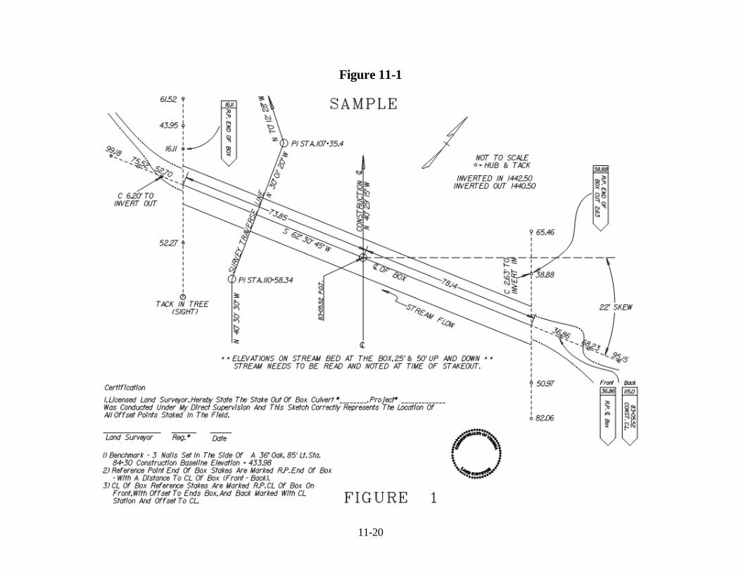
All box culverts are to be staked, according to furnished alignment and grades. The Contract Surveyor should check that the dimensions given for the culvert are consistent with the typical section of the roadway, giving attention that the toe of the slope intersects with the proper point of the culvert. Should any major differences be found, the Contract Surveyor is to immediately notify the Survey Manager so the differences can be resolved. For minor differences, such as the length of the culvert, the stakes for the proposed culvert should be adjusted to match the slope of the section, with notes made on the stakeout sketch and in red pencil on the contractor's and inspector's plans. Figure 11-L illustrates a procedure for checking the stake out of a box culvert. All culverts will be staked in accordance with Section 105.13 and 517 of the VDOT Road and Bridge Specifications and Figure 11-1. All pipe culverts, 48”and larger, and all culverts with design grades, are to be staked in accordance with Section 105.13 & 517 Road and Bridge Specifications. All pipe culverts less than 48” will be staked by contract personnel. All pipe culverts with design grades, such as storm sewers, regardless of size are to be staked by the Contract Surveyor. All pipe culverts that are in critical locations will be staked by the Contract Surveyor when specifically requested by the Project Engineer.

11-4
Sec. 11.07 Bridge Stakeout The Contract Surveyor should check the consistency between the stations and the
dimensions given on the bridge plans. If any difference is found, the Contract Surveyor should immediately notify the Survey Manager and the District Structure & Bridge Engineer so that the differences can be resolved. This check is necessary on all grade separation structures to ensure that the substructure is correctly located with respect to railroad tracks or under passing roads before construction is started.
The Contract Surveyor is to set stakes at the intersection of the baseline of the bridge and
the centerline of each pier. Also, stakes shall be set on the baseline of the bridge at the intersection of the lines shown on the plans on the abutments from which dimensions are referenced. These intersection points will be shown on the sub-structure layout sheet of the bridge plans. Angles are to be turned to the centerline of all piers and the lines shown on the plans on the abutments from which dimensions are referenced and stakes set on either of the bridge baseline on these centerlines. All bridge staking shall be in accordance with Section 105.13 and 517 of the VDOT Road and Bridge Specifications, Figure 11-J, and Figure 11-2 & Figure 11-3.
All measurements of distances and angles are to be checked thoroughly by the Contract Surveyor using different methods than that which was used for the initial layout. After completing the stakeout and thoroughly checking the same, the Contract Surveyor shall locate in red pencil on the layout sheet of the bridge plans used by the Project Inspector, and Contractor's Superintendent, all points which have been staked. This should be done in the presence of the Project Inspector and the Contractor's Superintendent or Engineer. The Contract Surveyor shall set an adequate number of stakes at 25’ intervals or less to locate the position of the toe of fill (or cut) in front of the two abutments. The Contract Surveyor should be certain that the road and bridge plans agree as to dimensions, rates of slope and super elevation on the abutment slopes. Sec. 11.08 Slope Stakes
Slope stakes shall be set at all stations in accordance with the latest standards. The correct method of marking and setting slope stakes is shown in Figure 11-K. For information on producing slope stakes notes, see Figures 11-E through 11-G. A careful examination should be made of the typical sections as shown, in regard to width of surfacing, width of shoulder and width of ditch, together with the cut or fill slopes or CS standards used (See Appendix D of the VDOT Construction Manual). Also, a careful examination should be made of the summary sheets, plan sheets, profile sheets, special notes pertaining to the staking and construction of the project, and the plan cross-sections to determine the suggested slope to be used in special cases. In case of a conflict, the Survey Manager will contact the Design Unit for clarification and when such clarification is given, staked accordingly. It is recommended that the slope stake listing from the DTM CADD file is secured as considerable time and effort can be saved with its use.

11-5
If slope staking is performed by data collection stakeout software, then electronic files may be submitted in place of notebooks. However any electronic file submitted would need to contain the same information that the slope stake notebooks contain. Such as the catch point information (distance, elevation, cut/fill) and the offset point information (distance, elevation, cut/fill). Anything less than this will be unacceptable, and in this case the slope stake information would need to be transferred into a notebook in the same format as discussed above. Sec. 11.09 Fine Grade Stakes
Fine grade or other stakes, required for the construction of the project, are to be set as the work progresses, with the exception of secondary roads. Fine grade stakes should be set on all projects on which the plans show definite grade lines. On tangents, the fine grade hubs are to be set on one side with distances and grades referenced to the finished grade on centerline. On curves, fine grade hubs may be required on both sides with offsets and grades referenced to the edges of pavement. Clear, concise notes are to be kept on fine grade stakes showing dates, etc. Fine grade hubs are not to be set for rough grading, as the slope stakes should suffice in these instances.
In regard to secondary projects, fine grade stakes will be set only on those with curb and gutter, unless otherwise requested by the Resident Engineer.
On projects where grading and paving is done under the same contract, only one set of
fine grade stakes are to be set. This one set of stakes is to be used for both cutting the fine grade and for paving. For marking fine grade stakes see Figure 11-I. (See Appendix D of the VDOT Construction Manual) Sec. 11.10 Right of Way Stakes
Hub and tack points (or equivalent) will be set for Standard RM-1 concrete monuments by the VDOT Surveyor as shown in Section 105.13 and Section 517 of the Road and Bridge Specifications. (specific reference is hereby made to section 105.13.1(h)(i) of the R&B Specs and section 504.01 and 504.02 of the R&B standards) Standard RM-2 steel pin or reinforcing bar and cap monuments will be set by the VDOT Survey Personnel or Consultant at the time of stakeout; or after construction is completed if pin location is within the construction limits.
In accordance with the Road Design Manual, Appendix C, Section 3, right of way
monuments will be installed (a) on the inside and outside of PC’s and PT’s, (b) along minor road until existing right of way is tied into, (c) all right of way breaks, (d) at beginning and end of project unless documented on previous project, and (e) at 500’ (urban), 1000’ (rural) and 2500’ (interstates) maximum intervals between right of way breaks. The monuments along right of way lines, to meet inter-visibility requirement, shall be estimated by studying the grades or may be left up to the party setting the monuments to be placed, but not exceeding the maximum intervals herein described. It is preferable to make an estimate from the plans to reduce the possible overrun on right of way monuments in the summaries.

11-6
Intermediate stakes for fencing will be set only on curves, and then only as needed. There may be instances on curves in rough terrain where staking by the VDOT or Contract Surveyor will be required, but in many cases the fence line can be established by measuring from the centerline. See Figure 11-I for marking standard RM-1 stakes. In all instances, the staking of all RM-1 & RM-2 monumentation shall be in accordance with Section 105.13 and 517 of the R&B Specs, Section 504 of the R&B Standards, and Figure 11-4 and Figure 11-5 herein. Sec. 11.11 Federal and Non-Federal Aid State Force Account Projects
Construction surveys for these type projects shall be made in accordance with the Provisions outlined in Section 105.13 and Section 517 of the Road and Bridge Specifications and the Construction Manual with its corresponding sections. Sec. 11.12 No-Plan Projects
No-plan projects typically require very limited survey effort and this is addressed in the contract by copied note “c105a0b-0702”. (See Sections 103.06 and 105.12 of the R&B Specs)
The location of any reference points that the Department may have established, and any control data which the Department may have available will be provided to the Contractor upon request. The Department will be responsible for the accuracy of such reference points and control data. (See Section 105.13.3 of the R&B Specs) Sec. 11.13 Minimum Plan Projects
Minimum Plan projects are either covered by Section 105.13 and 517 of the Road and Bridge Specifications or in the contract by Special Provision c105a0b-0702. (See Sections 103.06 and 105.12 of the R&B Specs) Sec. 11.14 Condemnation Staking Condemnation stakeouts will be performed by the Department and are not to be performed by the Contract Surveyor for the project. On all condemnation stakeouts, the following color codes will be used: Limited Access Line Mark with Blue Proposed Right of way Mark with Red Existing Right of way Mark with White Permanent Easement Mark with Green Temporary Easement Mark with Orange Utilities Mark with Yellow

11-7
Sec. 11.15 As-Built Plan of Right of Way Monumentation On projects where right of way monumentation is a plan quantity, an electronic “As-Built” plan needs to be submitted. Once construction has been completed and all R/W monumentation has been set, the Surveyor responsible for setting the monumentation shall provide an “As-built” survey of the right of way as required in Section 105.13 and Section 517 of the Road and Bridge Specifications. An example of what survey information is expected in the completed “As-Built” drawing is shown in Figure 11-5. Sec. 11.16 Submitting Survey Data As soon as the project is complete the Contract Surveyor should submit all survey notes, electronic files, and required “sealed” drawings to the Project Inspector. This information will be reviewed by the Survey Manager, and upon their approval that the survey information submitted meets all requirements, they will recommend to the Resident Engineer whether final payment should be made or if additional information should be required. For the current Construction Manual please click here: https://www.virginiadot.org/business/resources/const/ConstructionManual.pdf
For the current Post-Construction Manual please click here: https://www.virginiadot.org/business/resources/const/pc_manual.pdf
For the current Road and Bridge Specifications please click here: https://www.virginiadot.org/business/const/spec-default.asp
For the current Road and Bridge Standards please click here: https://www.virginiadot.org/business/locdes/vdot_road_and_bridge_standards.asp
For additional References and Manuals please click here: http://www.virginiadot.org/business/manuals-default.asp#Location

11-8
Figure 11-A

11-9
Figure 11-B
11-10
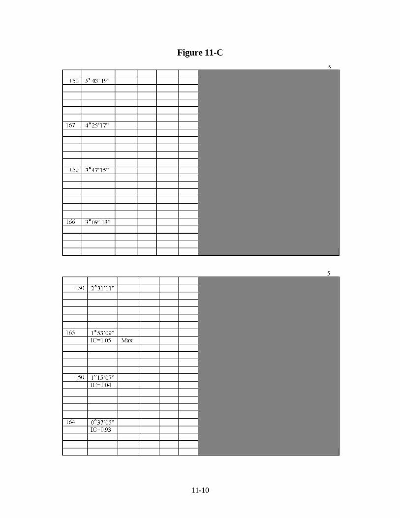
Figure 11-C

11-11
Figure 11-D

11-12
Figure 11-E

11-13
Figure 11-F

11-14
Figure 11-G

11-15
Figure 11-H

11-16
Figure 11-I

11-17
Figure 11-J

11-18
Figure 11-K

11-19
Figure 11-L Sketch Showing Procedure for Checking Box Culvert
Given:
Box Length (L) Box Height (H) Station and Finished Grade (A) Super Elevation (E) Flow Line Elevation (D) Pavement and Shoulder Width (R) Slope Rate (X) Delta (D)
Required: L1 and L2 Solution: Elevation “A” ± “E” = Elevation “B” Elevation Flow Line “D” + “H” = Elevation “C” “B” – “C” = “HI” “HI” x “X” = “S” “R” + “S” + “P” = L1 or L2 For Skew Angles: L1 or L2 = “R” + “S” + “P” Sin D
11-20
Figure 11-1

11-21
Figure 11-2

11-22
Figure 11-3

11-23
Figure 11-4

11-24
Figure 11-5