chapter 10: valves forpipe mounting -...
TRANSCRIPT
10-1
content10.INDD RH_19.12.07
Catalogue HY11-3500/UK
Parker Hannifin GmbH & Co. KGHydraulic Controls DivisionKaarst, Germany
10
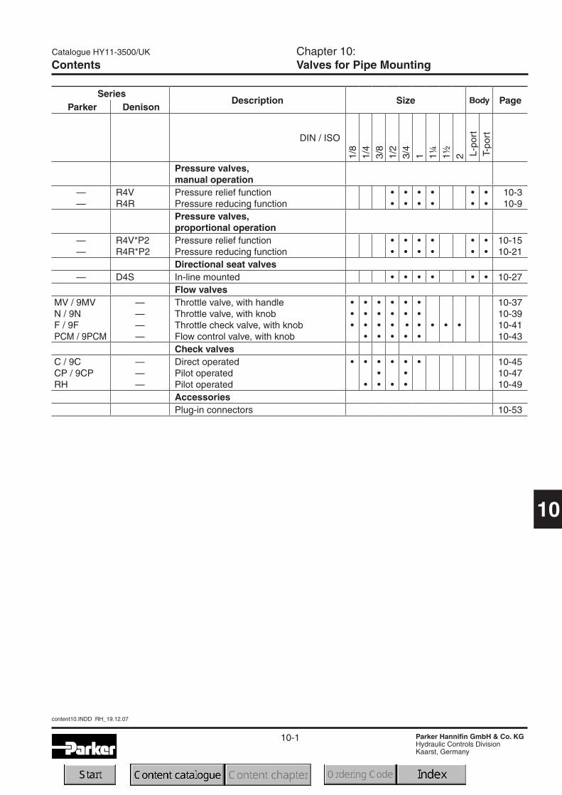
ContentsChapter 10:
Valves for Pipe Mounting
SeriesDescription Size Body Page
Parker Denison
DIN / ISO
1/8
1/4
3/8
1/2
3/4
1 1¼
1½
2 L-p
ort
T-port
Pressure valves,manual operation
—
—
R4V
R4R
Pressure relief function
Pressure reducing function
•
•
•
•
•
•
•
•
•
•
•
•
10-3
10-9
Pressure valves,proportional operation
—
—
R4V*P2
R4R*P2
Pressure relief function
Pressure reducing function
•
•
•
•
•
•
•
•
•
•
•
•
10-15
10-21
Directional seat valves— D4S In-line mounted • • • • • • 10-27
Flow valvesMV / 9MV
N / 9N
F / 9F
PCM / 9PCM
—
—
—
—
Throttle valve, with handle
Throttle valve, with knob
Throttle check valve, with knob
Flow control valve, with knob
•
•
•
•
•
•
•
•
•
•
•
•
•
•
•
•
•
•
•
•
•
•
•
• • •
10-37
10-39
10-41
10-43
Check valvesC / 9C
CP / 9CP
RH
—
—
—
Direct operated
Pilot operated
Pilot operated
• •
•
•
•
•
•
•
•
•
•
• 10-45
10-47
10-49
AccessoriesPlug-in connectors 10-53
10-2
content10.INDD RH_19.12.07
Catalogue HY11-3500/UK
Parker Hannifin GmbH & Co. KGHydraulic Controls DivisionKaarst, Germany
10
Notes
10-3
Catalogue HY11-3500/UK
Parker Hannifin GmbH & Co. KGHydraulic Controls DivisionKaarst, Germany
Pilot Operated Pressure Relief ValveSeries R4V (Denison)
10
R4V_UK.INDD RH_19.12.07
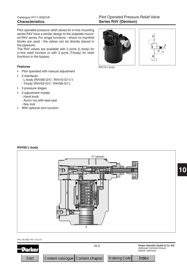
Characteristics
Pilot operated pressure relief valves for in-line mountingseries R4V have a similar design to the subplate mount-ed R4V series. For single functions - where no manifoldblocks are used - the valves can be directly placed inthe pipework.The R4V valves are available with 2 ports (L-body) forin-line relief function or with 3 ports (T-body) for relieffunctions in the bypass.
Features• Pilot operated with manual adjustment
• 2 interfaces- L-body (R4V06-G¾", R4V10-G1¼")- T-body (R4V03-G½", R4V06-G1")
• 3 pressure stages
• 3 adjustment modes- Hand knob- Acorn nut with lead seal- Key lock
• With optional vent function
R4V10 L-body
R4V06 L-body
10-4
R4V_UK.INDD RH_19.12.07
Catalogue HY11-3500/UK
Parker Hannifin GmbH & Co. KGHydraulic Controls DivisionKaarst, Germany
Pilot Operated Pressure Relief ValveSeries R4V (Denison)
10
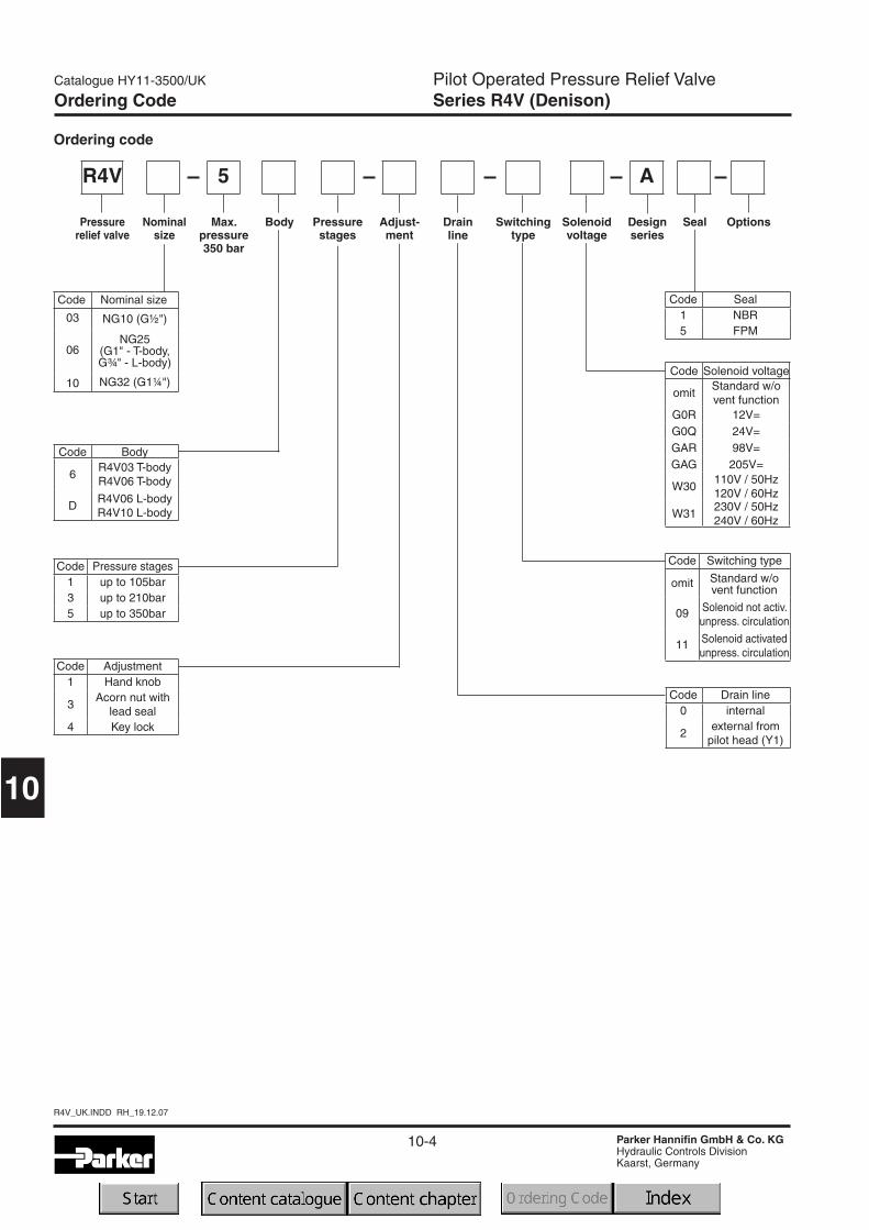
Code Seal1 NBR5 FPM
Code Nominal size
03 NG10 (G½")
06NG25
(G1" - T-body,G¾" - L-body)
10 NG32 (G1¼")
5 A
Ordering code
R4V
Max.pressure350 bar
Pressurestages
Pressurerelief valve
Designseries
Seal OptionsDrainline
Nominalsize
Code Body
6R4V03 T-bodyR4V06 T-body
DR4V06 L-bodyR4V10 L-body
Body
Code Pressure stages1 up to 105bar3 up to 210bar5 up to 350bar
Code Adjustment1 Hand knob
3Acorn nut with
lead seal4 Key lock
Adjust-ment
Switchingtype
Solenoidvoltage
Code Switching type
omit Standard w/ovent function
09 Solenoid not activ.unpress. circulation
11 Solenoid activatedunpress. circulation
Ordering Code
Code Drain line0 internal
2external from
pilot head (Y1)
Code Solenoid voltage
omitStandard w/ovent function
G0R 12V=G0Q 24V=GAR 98V=GAG 205V=
W30110V / 50Hz120V / 60Hz
W31230V / 50Hz240V / 60Hz

10-5
Catalogue HY11-3500/UK
Parker Hannifin GmbH & Co. KGHydraulic Controls DivisionKaarst, Germany
Pilot Operated Pressure Relief ValveSeries R4V (Denison)
10
R4V_UK.INDD RH_19.12.07
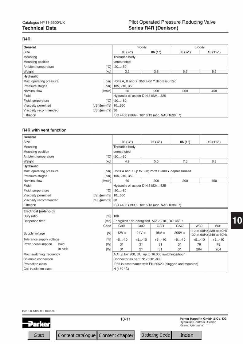
Technical Data
General T-body L-body
Size 03 (½") 06 (1") 06 (¾") 10 (1¼")Mounting Threaded body
Mounting position unrestricted
Ambient temperature [°C] -20...+50
Weight [kg] 3.2 6.6 3.3 5.6
HydraulicMax. operating pressure [bar] Ports A and X up to 350; Ports B and Y 30 bar
Pressure stages [bar] 105, 210, 350
Nominal flow [l/min] 60 200 200 450
Fluid Hydraulic oil as per DIN 51524...525
Fluid temperature [°C] -20...+80
Viscosity permitted [cSt]/[mm2/s] 10...650
Viscosity recommended [cSt]/[mm2/s] 30
Filtration ISO 4406 (1999) 18/16/13 (acc. NAS 1638: 7)
General T-body L-body
Size 03 (½") 06 (1") 06 (¾") 10 (1¼")Mounting Threaded body
Mounting position unrestricted
Ambient temperature [°C] -20...+50
Weight [kg] 4.9 8.3 5.0 7.3
HydraulicMax. operating pressure [bar] Ports A and X up to 350; Ports B and Y 30
Pressure stages [bar] 105, 210, 350
Nominal flow [l/min] 60 200 200 450
Fluid Hydraulic oil as per DIN 51524...525
Fluid temperature [°C] -20...+80
Viscosity permitted [cSt]/[mm2/s] 10...650
Viscosity recommended [cSt]/[mm2/s] 30
Filtration ISO 4406 (1999) 18/16/13 (acc. NAS 1638: 7)
R4V
R4V with vent function
Electrical (solenoid)Duty ratio [%] 100
Response time [ms] Energized / de-energized AC: 20/18 , DC: 46/27
Supply voltage
Tolerance supply voltage
Power consumption hold
in rush
Code
[V]
[%]
[W]
[W]
G0R G0Q GAR GAG W30 W31
12V = 24V = 98V = 205V =110 at 50Hz120 at 60Hz
230 at 50Hz240 at 60Hz
+5...-10 +5...-10 +5...-10 +5...-10 +5...-10 +5...-10
31 31 31 31 78 78
31 31 31 31 264 264
Max. switching frequency AC: up to7.200, DC: up to 16.000 switchings/hour
Solenoid connection Connector as per EN175301-803
Protection class IP65 in accordance with EN 60529 (plugged and mounted)
Coil insulation class H (180 °C)
10-6
R4V_UK.INDD RH_19.12.07
Catalogue HY11-3500/UK
Parker Hannifin GmbH & Co. KGHydraulic Controls DivisionKaarst, Germany
Pilot Operated Pressure Relief ValveSeries R4V (Denison)
10
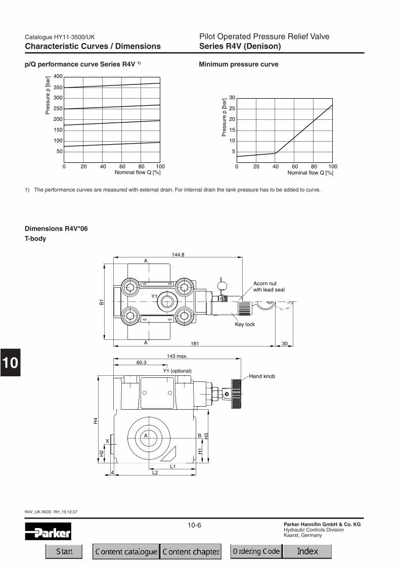
p/Q performance curve Series R4V 1) Minimum pressure curve
1) The performance curves are measured with external drain. For internal drain the tank pressure has to be added to curve.
Characteristic Curves / Dimensions
Dimensions R4V*06T-body
10-7
Catalogue HY11-3500/UK
Parker Hannifin GmbH & Co. KGHydraulic Controls DivisionKaarst, Germany
Pilot Operated Pressure Relief ValveSeries R4V (Denison)
10
R4V_UK.INDD RH_19.12.07
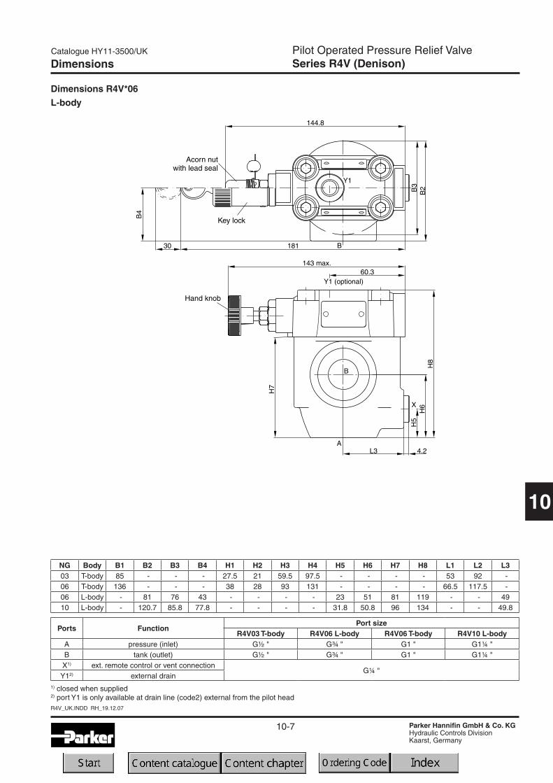
Dimensions R4V*06L-body
Dimensions
NG Body B1 B2 B3 B4 H1 H2 H3 H4 H5 H6 H7 H8 L1 L2 L303 T-body 85 - - - 27.5 21 59.5 97.5 - - - - 53 92 -06 T-body 136 - - - 38 28 93 131 - - - - 66.5 117.5 -06 L-body - 81 76 43 - - - - 23 51 81 119 - - 4910 L-body - 120.7 85.8 77.8 - - - - 31.8 50.8 96 134 - - 49.8
Ports FunctionPort size
R4V03 T-body R4V06 L-body R4V06 T-body R4V10 L-bodyA pressure (inlet) G½ " G¾ " G1 " G1¼ "B tank (outlet) G½ " G¾ " G1 " G1¼ "X1) ext. remote control or vent connection
G¼ "Y12) external drain
1) closed when supplied2) port Y1 is only available at drain line (code2) external from the pilot head
10-8
R4V_UK.INDD RH_19.12.07
Catalogue HY11-3500/UK
Parker Hannifin GmbH & Co. KGHydraulic Controls DivisionKaarst, Germany
Pilot Operated Pressure Relief ValveSeries R4V (Denison)
10
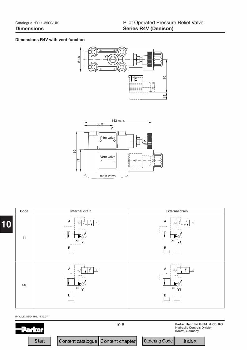
Dimensions R4V with vent function
Dimensions
Code Internal drain External drain
11
09

10-9
Catalogue HY11-3500/UK
Parker Hannifin GmbH & Co. KGHydraulic Controls DivisionKaarst, Germany
Pilot Operated Pressure Reducing ValveSeries R4R (Denison)
10
R4R_UK.INDD RH_13.03.08
Characteristics
Pilot operated pressure reducing valves for in-line mount-ing series R4R have a similar design to the subplate mount-ed R4R series. For single functions - where no manifoldblocks are used - the valves can be directly placed in thepipework.The valves are available with 2 ports (L-body) or with 3ports (T-body).
Features• Pilot operated with manual adjustment
• Normally closed to avoid undesired motion
• 2 interfaces- L-body (R4R06-G¾", R4R10-G1¼")- T-body (R4R03-G½", R4R06-G1")
• 3 pressure stages
• 3 adjustment modes- Hand knob- Acorn nut with lead seal- Key lock
• With optional vent function
R4R10 L-body
R4R06 L-body

10-10
R4R_UK.INDD RH_13.03.08
Catalogue HY11-3500/UK
Parker Hannifin GmbH & Co. KGHydraulic Controls DivisionKaarst, Germany
Pilot Operated Pressure Reducing ValveSeries R4R (Denison)
10
5 B
Ordering code
R4R
Max.pressure350 bar
Pressurestages
Pressure redu-cing valve
Designseries
Seal Options
2
Drainline ext.
from pilothead (Y1)
Nominalsize
Body
Code Pressure stages1 up to 105bar3 up to 210bar5 up to 350bar
Code Adjustment1 Hand knob
3Acorn nut with
lead seal4 Key lock
Adjust-ment
Switchingtype
Solenoidvoltage
Ordering Code
Code Seal1 NBR5 FPM
Code Nominal size
03 NG10 (G½")
06NG25
(G1" - T-body,G¾" - L-body)
10 NG32 (G1¼")
Code Body
6R4R03 T-bodyR4R06 T-body
DR4R06 L-bodyR4R10 L-body
Code Switching type
omit Standard w/ovent function
09 Solenoid not activ.unpress. circulation
11 Solenoid activatedunpress. circulation
Code Solenoid voltage
omitStandard w/ovent function
G0R 12V=G0Q 24V=GAR 98V=GAG 205V=
W30110V / 50Hz120V / 60Hz
W31230V / 50Hz240V / 60Hz
10-11
Catalogue HY11-3500/UK
Parker Hannifin GmbH & Co. KGHydraulic Controls DivisionKaarst, Germany
Pilot Operated Pressure Reducing ValveSeries R4R (Denison)
10
R4R_UK.INDD RH_13.03.08
Technical Data
General T-body L-body
Size 03 (½") 06 (1") 06 (¾") 10 (1¼")Mounting Threaded body
Mounting position unrestricted
Ambient temperature [°C] -20...+50
Weight [kg] 3.2 3.3 5.6 6.6
HydraulicMax. operating pressure [bar] Ports A, B and X: 350; Port Y depressurized
Pressure stages [bar] 105, 210, 350
Nominal flow [l/min] 60 200 200 450
Fluid Hydraulic oil as per DIN 51524...525
Fluid temperature [°C] -20...+80
Viscosity permitted [cSt]/[mm2/s] 10...650
Viscosity recommended [cSt]/[mm2/s] 30
Filtration ISO 4406 (1999) 18/16/13 (acc. NAS 1638: 7)
GeneralSize 03 (½") 06 (¾") 06 (1") 10 (1¼")Mounting Threaded body
Mounting position unrestricted
Ambient temperature [°C] -20...+50
Weight [kg] 4.9 5.0 7.3 8.3
HydraulicMax. operating pressure [bar] Ports A and X up to 350; Ports B and Y depressurized
Pressure stages [bar] 105, 210, 350
Nominal flow [l/min] 60 200 200 450
Fluid Hydraulic oil as per DIN 51524...525
Fluid temperature [°C] -20...+80
Viscosity permitted [cSt]/[mm2/s] 10...650
Viscosity recommended [cSt]/[mm2/s] 30
Filtration ISO 4406 (1999) 18/16/13 (acc. NAS 1638: 7)
R4R
R4R with vent function
Electrical (solenoid)Duty ratio [%] 100
Response time [ms] Energized / de-energized AC: 20/18 , DC: 46/27
Supply voltage
Tolerance supply voltage
Power consumption hold
in rush
Code
[V]
[%]
[W]
[W]
G0R G0Q GAR GAG W30 W31
12V = 24V = 98V = 205V =110 at 50Hz120 at 60Hz
230 at 50Hz240 at 60Hz
+5...-10 +5...-10 +5...-10 +5...-10 +5...-10 +5...-10
31 31 31 31 78 78
31 31 31 31 264 264
Max. switching frequency AC: up to7.200, DC: up to 16.000 switchings/hour
Solenoid connection Connector as per EN175301-803
Protection class IP65 in accordance with EN 60529 (plugged and mounted)
Coil insulation class H (180 °C)
10-12
R4R_UK.INDD RH_13.03.08
Catalogue HY11-3500/UK
Parker Hannifin GmbH & Co. KGHydraulic Controls DivisionKaarst, Germany
Pilot Operated Pressure Reducing ValveSeries R4R (Denison)
10
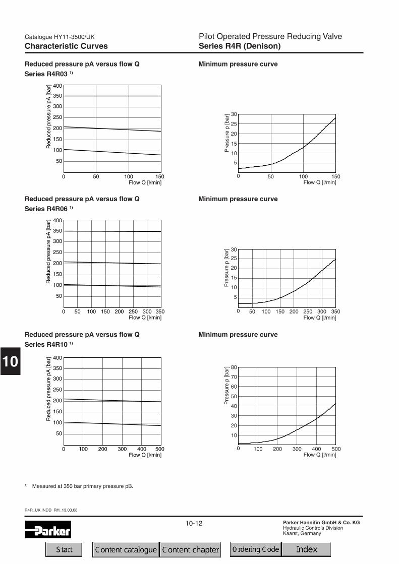
Characteristic Curves
Reduced pressure pA versus flow QSeries R4R03 1)
Reduced pressure pA versus flow QSeries R4R06 1)
Reduced pressure pA versus flow QSeries R4R10 1)
Minimum pressure curve
1) Measured at 350 bar primary pressure pB.
Minimum pressure curve
Minimum pressure curve
Pre
ssur
ep
[bar
]
5
0
10
15
20
25
30
10050 150Flow Q [l/min]
5
0
15
10
25
20
30
25015050 100 200 300 350Flow Q [l/min]
Pre
ssur
ep
[bar
]P
ress
ure
p[b
ar]
10
0
20
30
40
50
60
100 200 300 400 500Flow Q [l/min]
70
80
10-13
Catalogue HY11-3500/UK
Parker Hannifin GmbH & Co. KGHydraulic Controls DivisionKaarst, Germany
Pilot Operated Pressure Reducing ValveSeries R4R (Denison)
10
R4R_UK.INDD RH_13.03.08
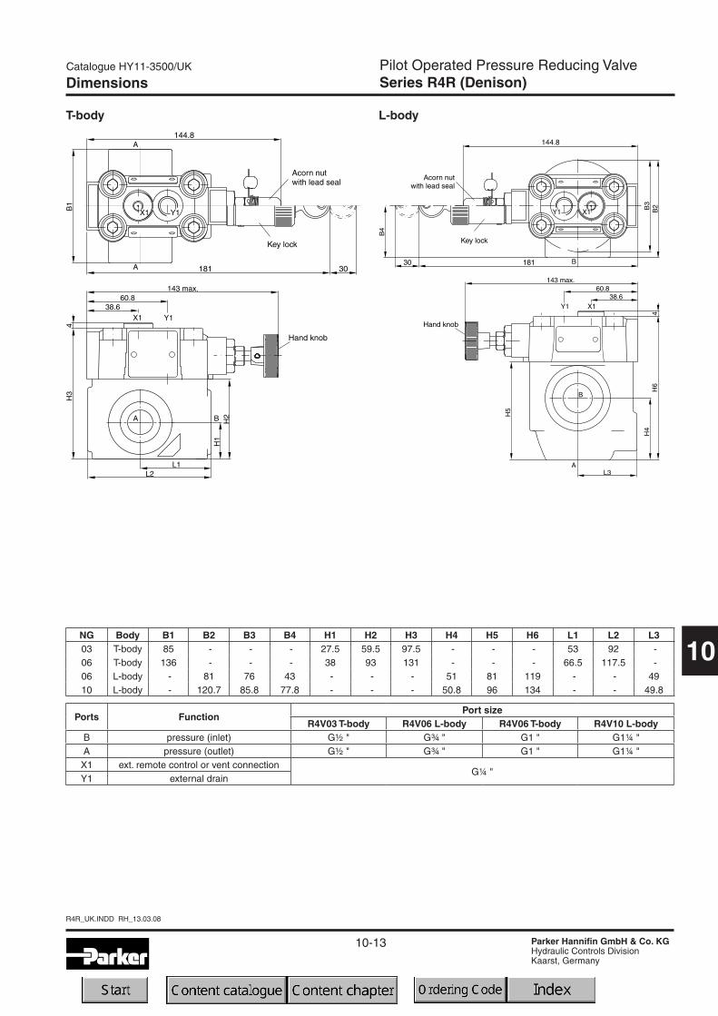
Dimensions
NG Body B1 B2 B3 B4 H1 H2 H3 H4 H5 H6 L1 L2 L303 T-body 85 - - - 27.5 59.5 97.5 - - - 53 92 -06 T-body 136 - - - 38 93 131 - - - 66.5 117.5 -06 L-body - 81 76 43 - - - 51 81 119 - - 4910 L-body - 120.7 85.8 77.8 - - - 50.8 96 134 - - 49.8
Ports FunctionPort size
R4V03 T-body R4V06 L-body R4V06 T-body R4V10 L-bodyB pressure (inlet) G½ " G¾ " G1 " G1¼ "A pressure (outlet) G½ " G¾ " G1 " G1¼ "
X1 ext. remote control or vent connectionG¼ "
Y1 external drain
T-body L-body

10-14
R4R_UK.INDD RH_13.03.08
Catalogue HY11-3500/UK
Parker Hannifin GmbH & Co. KGHydraulic Controls DivisionKaarst, Germany
Pilot Operated Pressure Reducing ValveSeries R4R (Denison)
10
Dimensions R4R with vent function
Dimensions
Code External drain
11
09

10-15
Catalogue HY11-3500/UK
Parker Hannifin GmbH & Co. KGHydraulic Controls DivisionKaarst, Germany
Pilot Operated Prop. Pressure Relief ValveSeries R4V*P2 (Denison)
10
R4VP2_UK.INDD RH_23.11.07
Proportional pressure relief valves series R4V*P2 arebased on the mechanically adjusted series R4V.The ad-ditional proportional unit between the mechanical pilotvalve and the main stage allows continuous pressureadjustment.The optimum performance can be achieved in combina-tion with the digital amplifier module PCD00A-400.
Features• Pilot operated with manual adjustment
• Continuous adjustment by proportional solenoid
• 2 interfaces
- L-body (R4V06-G¾", R4V10-G1¼")- T-body (R4V03-G½", R4V06-G1")
• 3 pressure stages
• With mechanical maximum pressure adjustment
Characteristics
R4V10*P2 L-body
R4V06*P2 L-body

10-16
R4VP2_UK.INDD RH_23.11.07
Catalogue HY11-3500/UK
Parker Hannifin GmbH & Co. KGHydraulic Controls DivisionKaarst, Germany
Pilot Operated Prop. Pressure Relief ValveSeries R4V*P2 (Denison)
10
Code Seal1 NBR5 FPM
5 A
Ordering code
R4V
Max.pressure350 bar
Pressurestages
Proportionalpressure
relief valve
Designseries
Seal OptionsSize Body
Code Pressure stages1 up to 105bar3 up to 210bar5 up to 350bar
Code Adjustment1 Hand knob
3Acorn nut with
lead seal
Adjust-ment
P2
Proportionalpressurecontrol
Solenoidvoltage12V=
Ordering Code / Technical Data
General T-body L-body
Size 03 (½") 06 (1") 06 (¾") 10 (1¼")Mounting Threaded body
Mounting position unrestricted
Ambient temperature [°C] -20...+50
Weight [kg] 5.0 5.1 7.4 8.4
HydraulicMax. operating pressure [bar] Ports A and X up to 350; Ports B and Y 30 bar
Pressure stages [bar] 105, 210, 350
Nominal flow [l/min] 60 200 200 450
Fluid Hydraulic oil as per DIN 51524...525
Fluid temperature [°C] -20...+80
Viscosity permitted [cSt]/[mm2/s] 20...380
Viscosity recommended [cSt]/[mm2/s] 30
Filtration ISO 4406 (1999) 18/16/13 (acc. NAS 1638: 7)
Technical data R4V*P2
Electrical (prop. solenoid)Duty ratio [%] 100
Nominal voltage [V] 12=
Max. current [A] 2.3
Coil resistance [Ohm] 4 at 20°C
Solenoid connection Connector as per EN175301-803
Protection class IP65 in accordance with EN 60529 (plugged and mounted)
Power amplifier PCD00A-400
G0R
Drainline
Code Drain line0 internal
2external from
pilot head (Y1)
Code Nominal size
03 NG10 (G½")
06NG25
(G1" - T-body,G¾" - L-body)
10 NG32 (G1¼")
Code Body
6R4V03 T-bodyR4V06 T-body
DR4V06 L-bodyR4V10 L-body
10-17
Catalogue HY11-3500/UK
Parker Hannifin GmbH & Co. KGHydraulic Controls DivisionKaarst, Germany
Pilot Operated Prop. Pressure Relief ValveSeries R4V*P2 (Denison)
10
R4VP2_UK.INDD RH_23.11.07
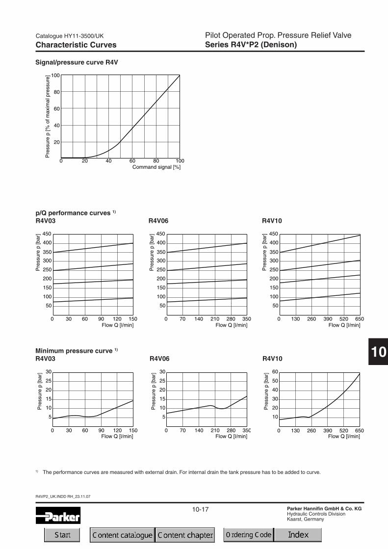
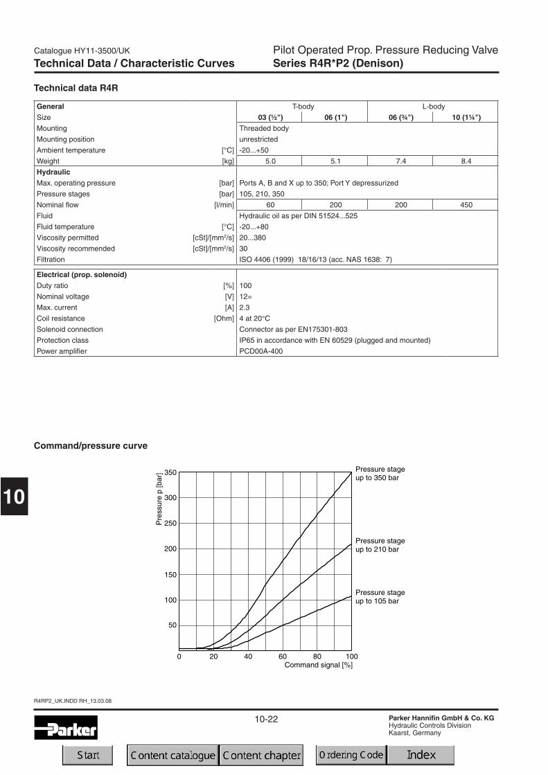
Characteristic Curves
Signal/pressure curve R4V
Minimum pressure curve 1)
R4V03 R4V06 R4V10
p/Q performance curves 1)
R4V03 R4V06 R4V10
1) The performance curves are measured with external drain. For internal drain the tank pressure has to be added to curve.
10-18
R4VP2_UK.INDD RH_23.11.07
Catalogue HY11-3500/UK
Parker Hannifin GmbH & Co. KGHydraulic Controls DivisionKaarst, Germany
Pilot Operated Prop. Pressure Relief ValveSeries R4V*P2 (Denison)
10
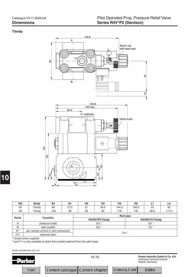
Dimensions
NG Body B1 H1 H2 H3 H4 H5 L1 L203 T-body 85 27.5 21 59.5 144.5 106.5 53 9206 T-body 136 38 28 93 178 140 66.5 117.5
T-body
Ports FunctionPort size
R4V03*P2 T-body R4V06*P2 T-bodyA pressure (inlet) G½ " G1 "B tank (outlet) G½ " G1 "X1) ext. remote control or vent connection
G¼ "Y12) external drain
1) closed when supplied2) port Y1 is only available at drain line (code2) external from the pilot head
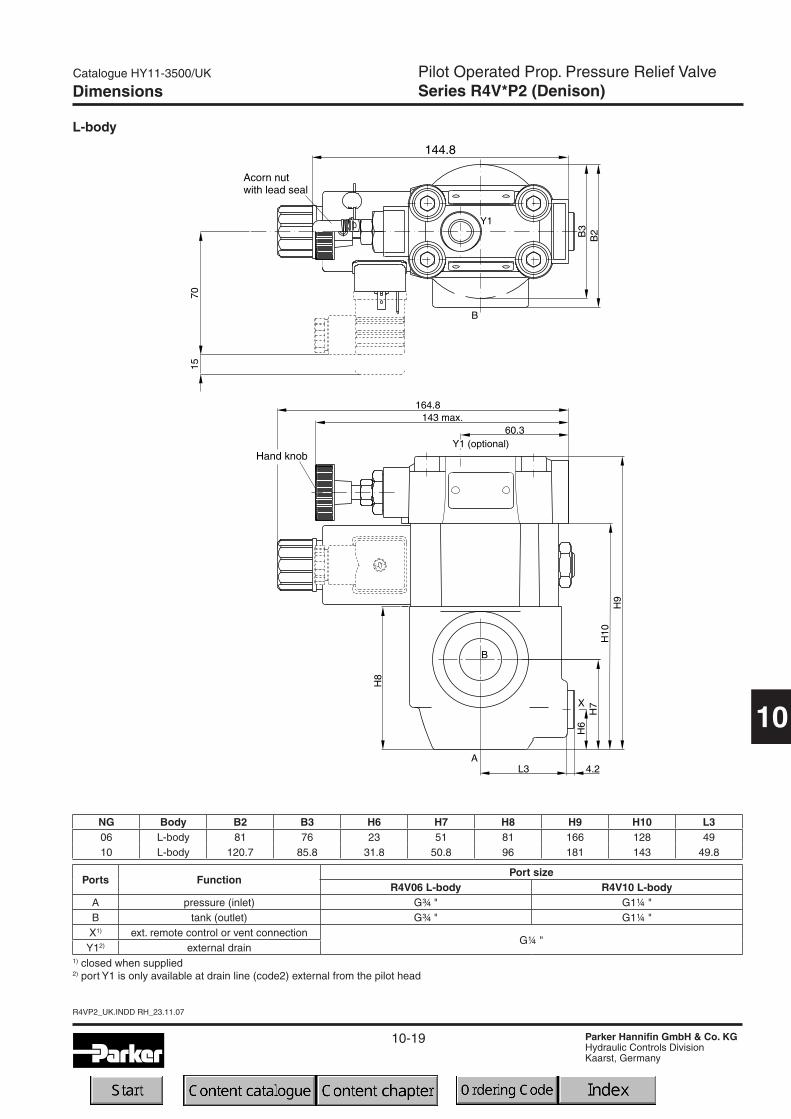
10-19
Catalogue HY11-3500/UK
Parker Hannifin GmbH & Co. KGHydraulic Controls DivisionKaarst, Germany
Pilot Operated Prop. Pressure Relief ValveSeries R4V*P2 (Denison)
10
R4VP2_UK.INDD RH_23.11.07
Dimensions
NG Body B2 B3 H6 H7 H8 H9 H10 L306 L-body 81 76 23 51 81 166 128 4910 L-body 120.7 85.8 31.8 50.8 96 181 143 49.8
L-body
Ports FunctionPort size
R4V06 L-body R4V10 L-bodyA pressure (inlet) G¾ " G1¼ "B tank (outlet) G¾ " G1¼ "X1) ext. remote control or vent connection
G¼ "Y12) external drain
1) closed when supplied2) port Y1 is only available at drain line (code2) external from the pilot head

10-20
R4VP2_UK.INDD RH_23.11.07
Catalogue HY11-3500/UK
Parker Hannifin GmbH & Co. KGHydraulic Controls DivisionKaarst, Germany
10
Notes
10-21
Catalogue HY11-3500/UK
Parker Hannifin GmbH & Co. KGHydraulic Controls DivisionKaarst, Germany
Pilot Operated Prop. Pressure Reducing ValveSeries R4R*P2 (Denison)
10
R4RP2_UK.INDD RH_13.03.08
Characteristics / Ordering Code
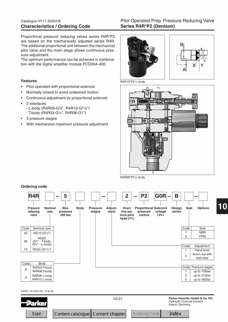
Proportional pressure reducing valves series R4R*P2are based on the mechanically adjusted series R4R.The additional proportional unit between the mechanicalpilot valve and the main stage allows continuous pres-sure adjustment.The optimum performance can be achieved in combina-tion with the digital amplifier module PCD00A-400.
Features• Pilot operated with proportional solenoid
• Normally closed to avoid undesired motion
• Continuous adjustment by proportional solenoid
• 2 interfaces
- L-body (R4R06-G¾", R4R10-G1¼")- T-body (R4R03-G½", R4R06-G1")
• 3 pressure stages
• With mechanical maximum pressure adjustment
R4R10*P2 L-body
R4R06*P2 L-body
5 B
Ordering code
R4R
Max.pressure350 bar
Pressurestages
Pressurereducing
valve
Designseries
Seal Options
2
Drainline ext.
from pilothead (Y1)
Nominalsize
Body Adjust-ment
P2
Proportionalpressurecontrol
Solenoidvoltage12V=
G0R
Code Seal1 NBR5 FPM
Code Pressure stages1 up to 105bar3 up to 210bar5 up to 350bar
Code Adjustment1 Hand knob
3Acorn nut with
lead seal
Code Nominal size
03 NG10 (G½")
06NG25
(G1" - T-body,G¾" - L-body)
10 NG32 (G1¼")
Code Body
6R4R03 T-bodyR4R06 T-body
DR4R06 L-bodyR4R10 L-body
10-22
R4RP2_UK.INDD RH_13.03.08
Catalogue HY11-3500/UK
Parker Hannifin GmbH & Co. KGHydraulic Controls DivisionKaarst, Germany
Pilot Operated Prop. Pressure Reducing ValveSeries R4R*P2 (Denison)
10
Technical Data / Characteristic Curves
General T-body L-body
Size 03 (½") 06 (1") 06 (¾") 10 (1¼")Mounting Threaded body
Mounting position unrestricted
Ambient temperature [°C] -20...+50
Weight [kg] 5.0 5.1 7.4 8.4
HydraulicMax. operating pressure [bar] Ports A, B and X up to 350; Port Y depressurized
Pressure stages [bar] 105, 210, 350
Nominal flow [l/min] 60 200 200 450
Fluid Hydraulic oil as per DIN 51524...525
Fluid temperature [°C] -20...+80
Viscosity permitted [cSt]/[mm2/s] 20...380
Viscosity recommended [cSt]/[mm2/s] 30
Filtration ISO 4406 (1999) 18/16/13 (acc. NAS 1638: 7)
Technical data R4R
Electrical (prop. solenoid)Duty ratio [%] 100
Nominal voltage [V] 12=
Max. current [A] 2.3
Coil resistance [Ohm] 4 at 20°C
Solenoid connection Connector as per EN175301-803
Protection class IP65 in accordance with EN 60529 (plugged and mounted)
Power amplifier PCD00A-400
Command/pressure curve
10-23
Catalogue HY11-3500/UK
Parker Hannifin GmbH & Co. KGHydraulic Controls DivisionKaarst, Germany
Pilot Operated Prop. Pressure Reducing ValveSeries R4R*P2 (Denison)
10
R4RP2_UK.INDD RH_13.03.08
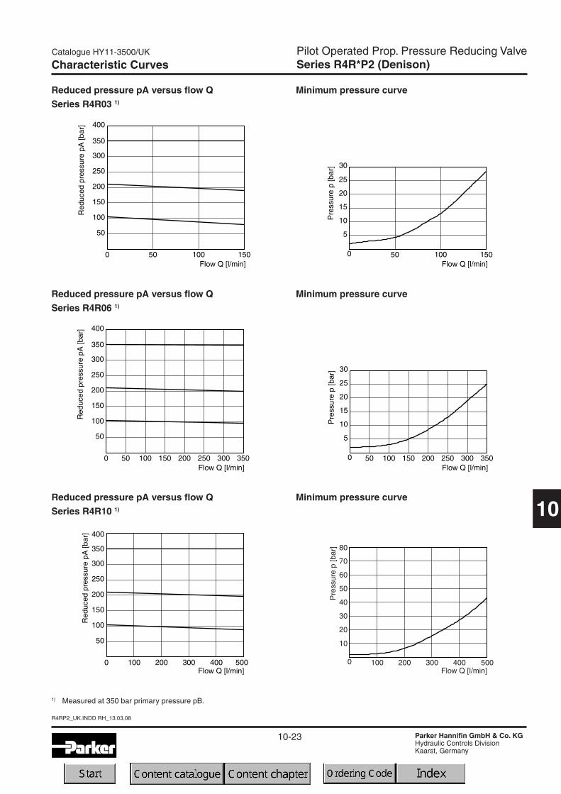
Characteristic Curves
Reduced pressure pA versus flow QSeries R4R03 1)
Reduced pressure pA versus flow QSeries R4R06 1)
Reduced pressure pA versus flow QSeries R4R10 1)
Minimum pressure curve
1) Measured at 350 bar primary pressure pB.
Minimum pressure curve
Minimum pressure curve
Pre
ssur
ep
[bar
]
10
0
20
30
40
50
60
100 200 300 400 500Flow Q [l/min]
70
80

10-24
R4RP2_UK.INDD RH_13.03.08
Catalogue HY11-3500/UK
Parker Hannifin GmbH & Co. KGHydraulic Controls DivisionKaarst, Germany
Pilot Operated Prop. Pressure Reducing ValveSeries R4R*P2 (Denison)
10
T-body
NG Body B1 H1 H2 H3 H4 L1 L203 T-body 85 27.5 59.5 144.5 106.5 53 9206 T-body 136 38 93 178 140 66.5 117.5
Dimensions
Ports FunctionPort size
R4V03*P2 T-body R4V06*P2 T-bodyB pressure (inlet) G½ " G1 "A pressure (outlet) G½ " G1 "X1 ext. remote control or vent connection
G¼ "Y1 external drain
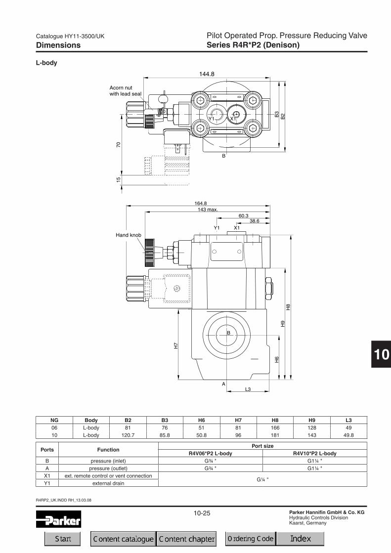
10-25
Catalogue HY11-3500/UK
Parker Hannifin GmbH & Co. KGHydraulic Controls DivisionKaarst, Germany
Pilot Operated Prop. Pressure Reducing ValveSeries R4R*P2 (Denison)
10
R4RP2_UK.INDD RH_13.03.08
L-body
NG Body B2 B3 H6 H7 H8 H9 L306 L-body 81 76 51 81 166 128 4910 L-body 120.7 85.8 50.8 96 181 143 49.8
Dimensions
Ports FunctionPort size
R4V06*P2 L-body R4V10*P2 L-bodyB pressure (inlet) G¾ " G1¼ "A pressure (outlet) G¾ " G1¼ "X1 ext. remote control or vent connection
G¼ "Y1 external drain

10-26
R4RP2_UK.INDD RH_13.03.08
Catalogue HY11-3500/UK
Parker Hannifin GmbH & Co. KGHydraulic Controls DivisionKaarst, Germany
10
Notes
10-27
Catalogue HY11-3500/UK
Parker Hannifin GmbH & Co. KGHydraulic Controls DivisionKaarst, Germany
Directional Seat ValveSeries D4S (Denison)
10
D4S_UK.INDD RH_19.12.07
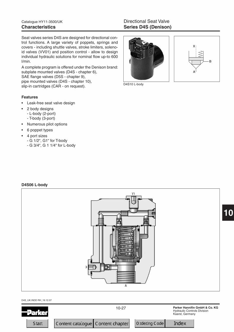
Characteristics
Seat valves series D4S are designed for directional con-trol functions. A large variety of poppets, springs andcovers - including shuttle valves, stroke limiters, soleno-id valves (VV01) and position control - allow to designindividual hydraulic solutions for nominal flow up-to 600l/min.
A complete program is offered under the Denison brand:subplate mounted valves (D4S - chapter 6),SAE flange valves (D5S - chapter 9),pipe mounted valves (D4S - chapter 10),slip-in cartridges (CAR - on request).
Features• Leak-free seat valve design
• 2 body designs- L-body (2-port)- T-body (3-port)
• Numerous pilot options
• 6 poppet types
• 4 port sizes- G 1/2“, G1“ for T-body- G 3/4“, G 1 1/4“ for L-body
D4S10 L-body
D4S06 L-body

10-28
D4S_UK.INDD RH_19.12.07
Catalogue HY11-3500/UK
Parker Hannifin GmbH & Co. KGHydraulic Controls DivisionKaarst, Germany
Directional Seat ValveSeries D4S (Denison)
10
Ordering Code
Code Optionsomit Standard
013Cover for
position control
Code Port size
03NG10
(CAR4 build-in)
06NG25
(CAR2 build-in)
10NG32
(CAR2 build-in)
D4S
Seatvalve
Spooltype
Nominalsize
Note: Combination examples at the end of chapter
Code Body Ports
6D4S03 T-bodyD4S06 T-body
A, B = G½"; X, Y1 = G¼"A, B = G1"; X, Y1 = G¼"
DD4S06 L-bodyD4S10 L-body
A, B = G¾"; X, Y1 = G¼"A, B = G1¼"; X, Y1 = G¼"
1) Springs 2, 3, 4 and 6 only
Body
Code Sleeve1 AA=95%, AB=5%3 AA=60%, AB=40%
B
Designseries
Seals
Code Pilot oil line in bodyA-X B-Y
1 internal from A2 internal from X
Code Ports X Y Z X-Y Y1 VV01Standard
1 Pilot oil = pilot drain — —C Pilot oil = pilot drain —
With solenoid valve (VV01)2 Ext. PD from cap —6 Internal pilot drain — —
With stroke limiter (not for D4S03)3 Pilot oil = pilot drain — — — —4 Pilot oil = pilot drain — — — —
Sleeve Switchingtype
Solenoidvoltage
Code Switching typeomit Standard w/o vent function09 VV01 with manual override de-energized: power
comp. open10 VV01 without manual override11 VV01 with manual override de-energized: power
comp. closed12 VV01 without manual override
CA Shuttle valve
DA Shuttle valve
CB VV01 code 09 and shuttle valve code CACD VV01 code 11 and shuttle valve code CADB VV01 code 09 and shuttle valve code DADD VV01 code 11 and shuttle valve code DA
BHVV01 code 10 and shuttle valve code CA and position
control 2) with amplifier
BKVV01 code 12 and shuttle valve code CA and position
control 2) with amplifier
BNVV01 code 10 and shuttle valve code DA and position
control 2) with amplifier
BQVV01 code 12 and shuttle valve code DA and position
control 2) with amplifierBC VV01 code 10 and position control 2) with amplifierBE VV01 code 12 and position control 2) with amplifierBA Position control 2) with amplifierBF Position control 2) with amplifier and shuttle valve code CABL Position control 2) with amplifier and shuttle valve code DA
Capversion
Pilotconnection
Code Size Poppet type Sleeve
1 03, 06,10With closed bottom and 15° chamfer (pZ max.
= pA +20bar1
203
With 0.8 dia. orifice at the bottom and 15°chamfer
1
06, 10With 1.2 dia. orifice at the bottom and 15°
chamfer1
4 03, 06,10 With closed bottom and 45° chamfer 1, 3A1) 06, 10 Safety spool (for position control only) 3B1) 06, 10 Throttle spool, 10° chamfer 3C1) 06, 10 Throttle spool, 3° chamfer 3
open bore closed bore orifice Ø 1.2
Code Seals1 NBR5 FPM
2) Position control for D4S06/10 only.Spring 2 or 4. Spool A and sleeve 3.Valve open: proximity switch damped
OptionsSpring
Code
Spring (approx. cracking pressure [bar]Sleeve Code 1 Sleeve Code 3
A -> B A -> B B -> AD5S03 D5S06/10 D5S03 D5S06/10 D5S03 D5S06/10
1 2.8 3.5 6.5 6.5 9.5 11.02 0.5 0.5 1.0 1.0 1.5 1.73 0.3 0.3 0.6 0.6 0.9 1.04 2.2 2.2 4.0 3.5 5.5 6.05 — 9.0 — 16.0 — 28.06 1.2 1.2 2.0 2.2 3.0 3.87 3.0 — 8.0 — 12.0 —
Code Solenoid voltage
omit Standard w/o vent function
G0R 12V=
G0Q 24V=
GAR 98V=
GAG 205V=
W30 110V / 50Hz ; 120V / 60Hz
W31 230V / 50Hz ; 240V / 60Hz
10-29
Catalogue HY11-3500/UK
Parker Hannifin GmbH & Co. KGHydraulic Controls DivisionKaarst, Germany
Directional Seat ValveSeries D4S (Denison)
10
D4S_UK.INDD RH_19.12.07
Electrical (solenoid)Duty ratio [%] 100
Response time [ms] Energized / de-energized AC: 20/18 , DC: 46/27
Code G0R G0Q GAR GAG W30 W31
12V = 24V = 98V = 205V =110 at 50Hz120 at 60Hz
230 at 50Hz240 at 60Hz
+5...-10 +5...-10 +5...-10 +5...-10 +5...-10 +5...-10
31 31 31 31 78 78
31 31 31 31 264 264
Supply voltage [V]
Tolerance supply voltage [%]
Power consumption, hold [W]
Power consumption, in rush [W]
Max. switching frequency [1/h] AC: up to 7.200, DC: up to 16.000 switchings/hour
Solenoid connection Connector as per EN175301-803
Protection class IP65 in accordance with EN 60529 (plugged and mounted)
Coil insulation class H (180 °C)
General T-body L-body
Size 03 (½") 06 (1") 06 (¾") 10 (1¼")Mounting Threaded body
Mounting position unrestricted
Ambient temperature [°C] -20...+50
Weight D4S T-body [kg] 3.2 6.6 — —
D4S L-body [kg] — — 3.3 5.6
HydraulicMax. operating pressure [bar] Ports A, B up to 350; Port Y 140 (with VV01)
Nominal flow [l/min] 180 360 360 600
Fluid Hydraulic oil as per DIN 51524...525
Fluid temperature [°C] -20...+80
Viscosity permitted [cSt]/[mm2/s] 10...650
Viscosity recommended [cSt]/[mm2/s] 30
Filtration ISO 4406 (1999) 18/16/13 (acc. NAS 1638: 7)
Technical Data
Technical data
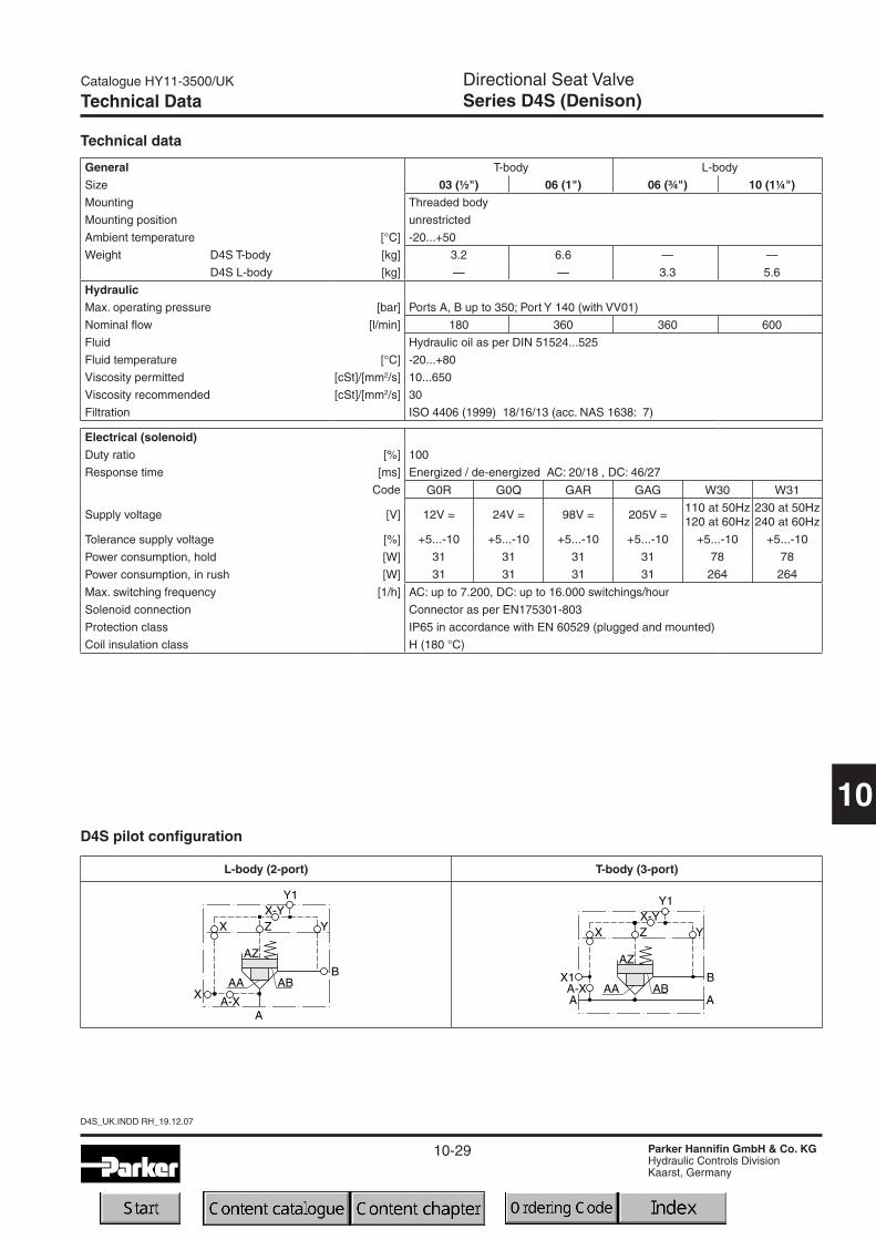
D4S pilot configuration
L-body (2-port) T-body (3-port)
10-30
D4S_UK.INDD RH_19.12.07
Catalogue HY11-3500/UK
Parker Hannifin GmbH & Co. KGHydraulic Controls DivisionKaarst, Germany
Directional Seat ValveSeries D4S (Denison)
10
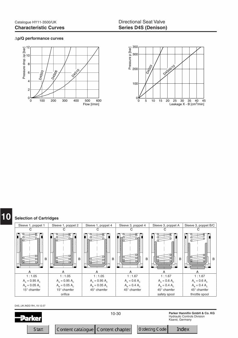
Characteristic Curves
Dp/Q performance curves
Sleeve 1, poppet 1 Sleeve 1, poppet 2 Sleeve 1, poppet 4 Sleeve 3, poppet 4 Sleeve 3, poppet A Sleeve 3, poppet B/C
1 : 1.05 1 : 1.05 1 : 1.05 1 : 1.67 1 : 1.67 1 : 1.67AA = 0.95 AC AA = 0.95 AC AA = 0.95 AC AA = 0.6 AC AA = 0.6 AC AA = 0.6 AC
AB = 0.05 AC AB = 0.05 AC AB = 0.05 AC AB = 0.4 AC AB = 0.4 AC AB = 0.4 AC
15° chamfer 15° chamfer 45° chamfer 45° chamfer 45° chamfer 45° chamferorifice safety spool throttle spool
Selection of Cartridges
10-31
Catalogue HY11-3500/UK
Parker Hannifin GmbH & Co. KGHydraulic Controls DivisionKaarst, Germany
Directional Seat ValveSeries D4S (Denison)
10
D4S_UK.INDD RH_19.12.07
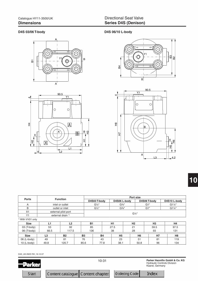
D4S 03/06 T-body D4S 06/10 L-body
Dimensions
Ports FunctionPort size
D4S03 T-body D4S06 L-body D4S06 T-body D4S10 L-bodyA inlet or outlet G½" G¾" G1" G1¼"B outlet or inlet G½" G¾" G1" G1¼"X1 external pilot port
G¼"Y1 external drain 1)
Size L1 L2 B1 H1 H2 H3 H403 (T-body) 53 92 85 27.5 21 59.5 97.506 (T-body) 66.5 117.5 136 38 28 93 131
1) With VV01 only
Size L3 B2 B3 B4 H5 H6 H7 H806 (L-body) 49 81 76 43 23 51 81 11910 (L-body) 49.8 120.7 85.6 77.8 38.1 50.8 96 134
10-32
D4S_UK.INDD RH_19.12.07
Catalogue HY11-3500/UK
Parker Hannifin GmbH & Co. KGHydraulic Controls DivisionKaarst, Germany
Directional Seat ValveSeries D4S (Denison)
10
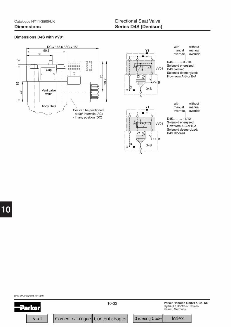
Dimensions D4S with VV01
Dimensions

10-33
Catalogue HY11-3500/UK
Parker Hannifin GmbH & Co. KGHydraulic Controls DivisionKaarst, Germany
Directional Seat ValveSeries D4S (Denison)
10
D4S_UK.INDD RH_19.12.07
Position control by proximity switch (incl. amplifier)Valve open: proximity switch activated.
This proximity switch is pressure proof and has no wea-ring parts.
NotePosition control for D4S06 and D4S10 only.
Dimensions D4S position control
Dimensions
Dimensions D4S stroke limiter
Function PNP, contactSupply voltage (Us) [VDC] 10...30Supply voltage ripple [%] £ 10Current consumption [mA] max. 8Residual voltage L-signal [V] Us - 2.2 at lmax
Output current (I) [mA] £ 200Protection class IP67Ambient temperature [C°] -25...+70Wire cross section [mm2] 3 x 0.5
Note:Stroke limiter not for use with D4S03, VV01, shuttle valve and positon control.
10-34
D4S_UK.INDD RH_19.12.07
Catalogue HY11-3500/UK
Parker Hannifin GmbH & Co. KGHydraulic Controls DivisionKaarst, Germany
Directional Seat ValveSeries D4S (Denison)
10
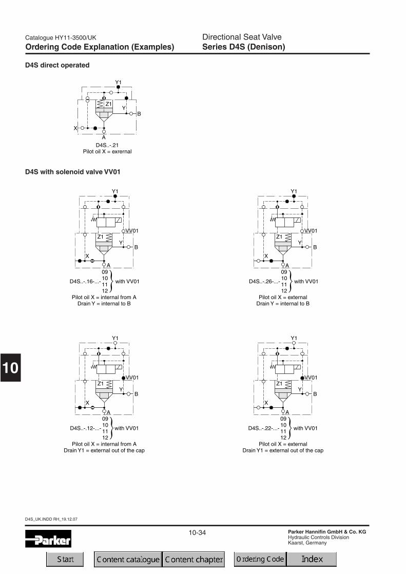
Ordering Code Explanation (Examples)
D4S direct operated
D4S with solenoid valve VV01
10-35
Catalogue HY11-3500/UK
Parker Hannifin GmbH & Co. KGHydraulic Controls DivisionKaarst, Germany
Directional Seat ValveSeries D4S (Denison)
10
D4S_UK.INDD RH_19.12.07
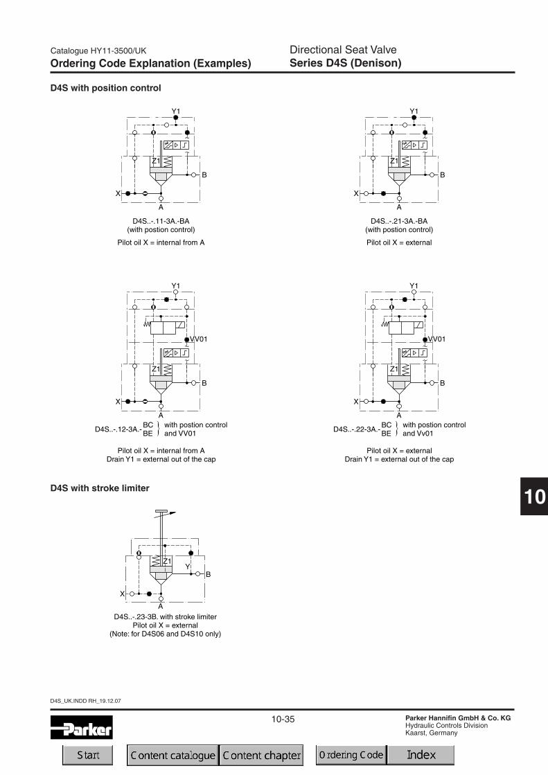
Ordering Code Explanation (Examples)
D4S with position control
D4S with stroke limiter

10-36
D4S_UK.INDD RH_19.12.07
Catalogue HY11-3500/UK
Parker Hannifin GmbH & Co. KGHydraulic Controls DivisionKaarst, Germany
10
Notes
10-37
Catalogue HY11-3500/UK
Parker Hannifin GmbH & Co. KGHydraulic Controls DivisionKaarst, Germany
10
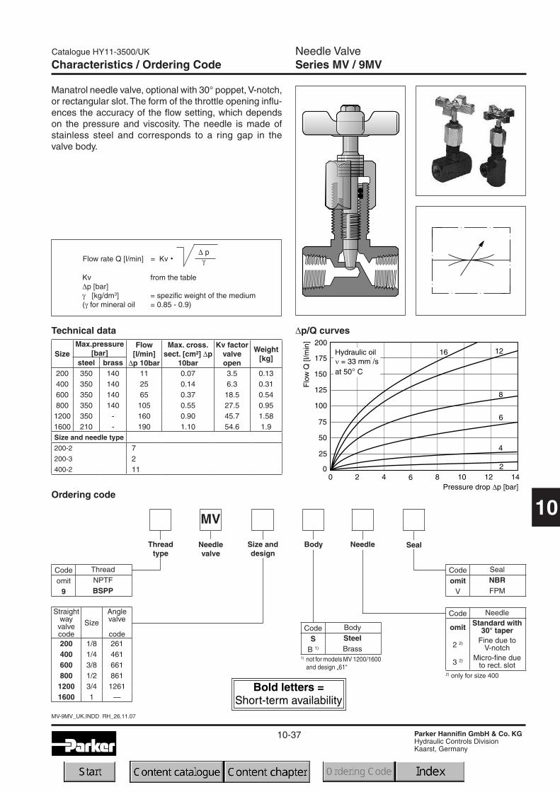
Needle ValveSeries MV / 9MV
MV-9MV_UK.INDD RH_26.11.07
SizeMax.pressure
[bar]Flow
[l/min]∆p 10bar
Max. cross.sect. [cm²] ∆p
10bar
Kv factorvalveopen
Weight[kg]steel brass
200 350 140 11 0.07 3.5 0.13400 350 140 25 0.14 6.3 0.31600 350 140 65 0.37 18.5 0.54800 350 140 105 0.55 27.5 0.951200 350 - 160 0.90 45.7 1.581600 210 - 190 1.10 54.6 1.9Size and needle type
200-2 7200-3 2400-2 11
Characteristics / Ordering Code
Ordering code
∆p/Q curves
Manatrol needle valve, optional with 30° poppet, V-notch,or rectangular slot.The form of the throttle opening influ-ences the accuracy of the flow setting, which dependson the pressure and viscosity. The needle is made ofstainless steel and corresponds to a ring gap in thevalve body.
Technical data
1) not for models MV 1200/1600and design „61“
2) only for size 400
Kv from the table∆p [bar]γ [kg/dm3] = spezific weight of the medium(γ for mineral oil = 0.85 - 0.9)
Flow rate Q [l/min] = Kv · ∆ pγ
Straightwayvalvecode
Size
Anglevalve
code200 1/8 261400 1/4 461600 3/8 661800 1/2 8611200 3/4 12611600 1 —
MV
SealNeedleNeedlevalve
Size anddesign
Code Seal
omit NBR
V FPM
Code Needle
omit Standard with30° taper
2 2) Fine due toV-notch
3 2) Micro-fine dueto rect. slot
Threadtype
Code Thread
omit NPTF
9 BSPP
Code Body
S Steel
B 1) Brass
Body
10-38
MV-9MV_UK.INDD RH_26.11.07
Catalogue HY11-3500/UK
Parker Hannifin GmbH & Co. KGHydraulic Controls DivisionKaarst, Germany
10
Needle ValveSeries MV / 9MV
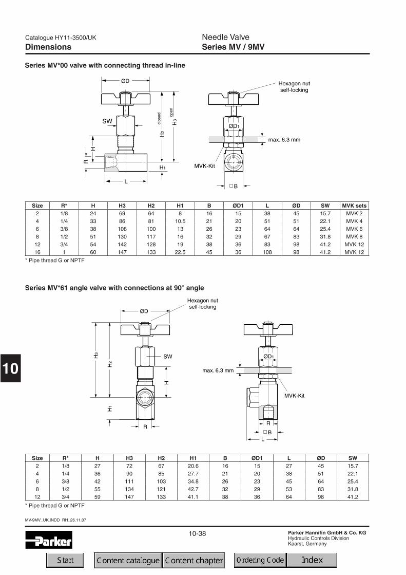
Size R* H H3 H2 H1 B ØD1 L ØD SW2 1/8 27 72 67 20.6 16 15 27 45 15.74 1/4 36 90 85 27.7 21 20 38 51 22.16 3/8 42 111 103 34.8 26 23 45 64 25.48 1/2 55 134 121 42.7 32 29 53 83 31.8
12 3/4 59 147 133 41.1 38 36 64 98 41.2
Size R* H H3 H2 H1 B ØD1 L ØD SW MVK sets2 1/8 24 69 64 8 16 15 38 45 15.7 MVK 24 1/4 33 86 81 10.5 21 20 51 51 22.1 MVK 46 3/8 38 108 100 13 26 23 64 64 25.4 MVK 68 1/2 51 130 117 16 32 29 67 83 31.8 MVK 812 3/4 54 142 128 19 38 36 83 98 41.2 MVK 1216 1 60 147 133 22.5 45 36 108 98 41.2 MVK 12
Dimensions
Series MV*00 valve with connecting thread in-line
Series MV*61 angle valve with connections at 90° angle
* Pipe thread G or NPTF
* Pipe thread G or NPTF
10-39
Catalogue HY11-3500/UK
Parker Hannifin GmbH & Co. KGHydraulic Controls DivisionKaarst, Germany
10
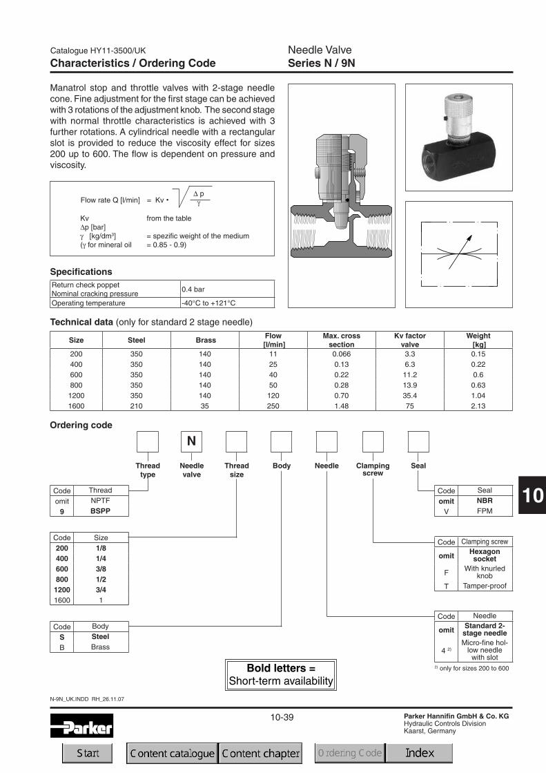
Needle ValveSeries N / 9N
N-9N_UK.INDD RH_26.11.07
Size Steel BrassFlow[l/min]
Max. crosssection
Kv factorvalve
Weight[kg]
200 350 140 11 0.066 3.3 0.15400 350 140 25 0.13 6.3 0.22600 350 140 40 0.22 11.2 0.6800 350 140 50 0.28 13.9 0.63
1200 350 140 120 0.70 35.4 1.041600 210 35 250 1.48 75 2.13
Technical data (only for standard 2 stage needle)
Manatrol stop and throttle valves with 2-stage needlecone. Fine adjustment for the first stage can be achievedwith 3 rotations of the adjustment knob. The second stagewith normal throttle characteristics is achieved with 3further rotations. A cylindrical needle with a rectangularslot is provided to reduce the viscosity effect for sizes200 up to 600. The flow is dependent on pressure andviscosity.
Return check poppetNominal cracking pressure
0.4 bar
Operating temperature -40°C to +121°C
Specifications
Kv from the table∆p [bar]γ [kg/dm3] = spezific weight of the medium(γ for mineral oil = 0.85 - 0.9)
Flow rate Q [l/min] = Kv · ∆ pγ
2) only for sizes 200 to 600
Ordering code
Code Size200 1/8400 1/4600 3/8800 1/21200 3/41600 1
N
Clampingscrew
NeedleNeedlevalve
Threadsize
Code Seal
omit NBR
V FPM
Code Needle
omit Standard 2-stage needle
4 2)Micro-fine hol-
low needlewith slot
Threadtype
Code Thread
omit NPTF
9 BSPP
Code Body
S Steel
B Brass
Body Seal
Code Clamping screw
omit Hexagonsocket
FWith knurled
knob
T Tamper-proof
Characteristics / Ordering Code
10-40
N-9N_UK.INDD RH_26.11.07
Catalogue HY11-3500/UK
Parker Hannifin GmbH & Co. KGHydraulic Controls DivisionKaarst, Germany
10
Needle ValveSeries N / 9N
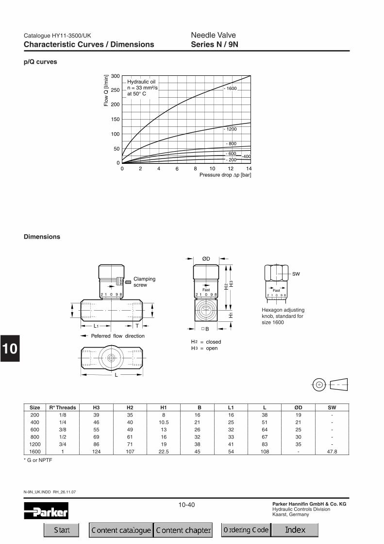
p/Q curves
Characteristic Curves / Dimensions
Hexagon adjustingknob, standard forsize 1600
Dimensions
Size R* Threads H3 H2 H1 B L1 L ØD SW200 1/8 39 35 8 16 16 38 19 -400 1/4 46 40 10.5 21 25 51 21 -600 3/8 55 49 13 26 32 64 25 -800 1/2 69 61 16 32 33 67 30 -1200 3/4 86 71 19 38 41 83 35 -1600 1 124 107 22.5 45 54 108 - 47.8
* G or NPTF
10-41
Catalogue HY11-3500/UK
Parker Hannifin GmbH & Co. KGHydraulic Controls DivisionKaarst, Germany
10
F-9F_UK.INDD RH_26.11.07
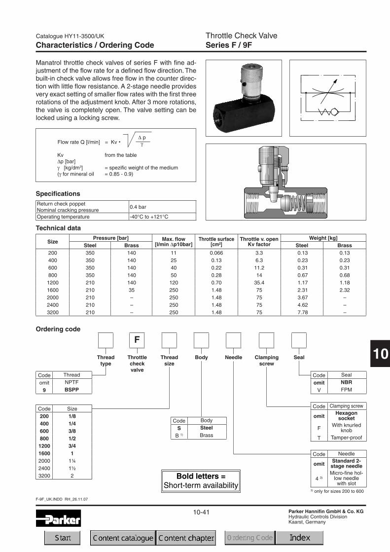
Throttle Check ValveSeries F / 9FCharacteristics / Ordering Code
3) only for sizes 200 to 600
Ordering code
Code Size200 1/8400 1/4600 3/8800 1/21200 3/41600 12000 1¼2400 1½3200 2
F
Clampingscrew
NeedleThrottlecheckvalve
Threadsize
Code Seal
omit NBR
V FPM
Code Needle
omit Standard 2-stage needle
4 3)Micro-fine hol-
low needlewith slot
Threadtype
Code Thread
omit NPTF
9 BSPP
Code Body
S Steel
B 1) Brass
Body Seal
Code Clamping screw
omit Hexagonsocket
FWith knurled
knob
T Tamper-proof
Manatrol throttle check valves of series F with fine ad-justment of the flow rate for a defined flow direction. Thebuilt-in check valve allows free flow in the counter direc-tion with little flow resistance. A 2-stage needle providesvery exact setting of smaller flow rates with the first threerotations of the adjustment knob. After 3 more rotations,the valve is completely open. The valve setting can belocked using a locking screw.
Specifications
Kv from the table∆p [bar]γ [kg/dm3] = spezific weight of the medium(γ for mineral oil = 0.85 - 0.9)
Flow rate Q [l/min] = Kv · ∆ pγ
Return check poppetNominal cracking pressure
0.4 bar
Operating temperature -40°C to +121°C
SizePressure [bar] Max. flow
[l/min ∆p10bar]Throttle surface
[cm²]Throttle v. open
Kv factorWeight [kg]
Steel Brass Steel Brass200 350 140 11 0.066 3.3 0.13 0.13400 350 140 25 0.13 6.3 0.23 0.23600 350 140 40 0.22 11.2 0.31 0.31800 350 140 50 0.28 14 0.67 0.681200 210 140 120 0.70 35.4 1.17 1.181600 210 35 250 1.48 75 2.31 2.322000 210 – 250 1.48 75 3.67 –2400 210 – 250 1.48 75 4.62 –3200 210 – 250 1.48 75 7.78 –
Technical data

10-42
F-9F_UK.INDD RH_26.11.07
Catalogue HY11-3500/UK
Parker Hannifin GmbH & Co. KGHydraulic Controls DivisionKaarst, Germany
10
Throttle Check ValveSeries F / 9FCharacteristic Curves / Dimensions
Controlled flow vs. pressure drop needle fully open Free flow vs. pressure drop needle fully open
Size R* H3 H2 H1 B L1 L ØD SW T200 1/8 39 35 8 16 36 51 19 - 9400 1/4 46 40 10.5 21 43 67 21 - 13600 3/8 55 49 13 26 45 70 25 - 13800 1/2 69 61 16 32 57 87 30 - 161200 3/4 86 71 19 38 65 99 35 - 171600 1 124 107 22.5 45 83 127 - 47.8 202000 1 1/4 130 114 29 58 99 143 - - 21.52400 1 1/2 137 120 35 70 114 143 - - 23.53200 2 146 130 44.5 89 134 165 - - 25
* Pipe thread G or NPTF
Dimensions
Hexagon adjustingknob, standard forsizes 1600 to 3200

10-43
Catalogue HY11-3500/UK
Parker Hannifin GmbH & Co. KGHydraulic Controls DivisionKaarst, Germany
10
Flow Control ValveSeries PCM / 9PCM
PCM-9PCM_UK.INDD RH_26.11.07
Characteristics / Ordering Code
Ordering code
SPC
Clampingscrew
Designseries
Press.comp. flow
controlvalve
Threadsize
Code Seal
omit NBR
V FPM
Threadtype
Code Thread
omit NPTF
9 BSPP
Steelbody
Seal
Code Clamping screw
omit Hexagonsocket
FWith knurled
knob
T 2) Tamper-proof
Manatrol 2 way flow control valves for pressure compen-sated regulation of the flow rate. As a consequence ofpressure changes, the set value can vary by ± 5% withinthe tolerance range. Viscosity changes have the sameeffect and are to be observed.
* Min. and max. flow rate
Technical data
PCM
PCCM
SizeMax.
press.[bar]
Flow control Check valve Weight[kg]Q* [l/min] ∆p
[bar]Qmax
[l/min]∆p
[bar]400 210 1 - 10 7 20 3 0.82600 210 2 - 25 7 30 3 1.05800 210 6 - 60 11 75 8 1.68
1200 210 10 - 100 11 130 8 3.641600 210 19 - 190 11 250 10 6.59
Design
(is determinedby factory)
Code Size400 1/4600 3/8800 1/21200 3/41600 1
Code Design
omit Without checkvalve
CWith check
valve
M
2) not available abovesize 1200

10-44
PCM-9PCM_UK.INDD RH_26.11.07
Catalogue HY11-3500/UK
Parker Hannifin GmbH & Co. KGHydraulic Controls DivisionKaarst, Germany
10
Flow Control ValveSeries PCM / 9PCMCharacteristic Curves / Dimensions
Size R* H3 H2 B L1 B1 L2 ØD SW400 1/4 69 64 35 16 18 92 21 -600 3/8 80 74 38 18 19 106 25 -800 1/2 103 95 44 22 22 125 30 -1200 3/4 128 116 57 28 29 149 35 -1600 1 175 158 70 33 35 176 - 47.8
* Pipe thread G or NPTF
Dimensions
Hexagon ad-justing knob,standard forsize 1600
The curves refer to hydraulic oil of 33 cSt / 50°C.
Size 400 - 1600 p/Q control characteristic∆p/Q curves
Sizes 400, 600 and 1200:Pressure drop ∆p for flowthrough check valve inrange Qmax / Qmin with eachsize
Sizes 800 and 1600:Pressure drop ∆p for flowthrough check valve inrange Qmax / Qmin with eachsize
10-45
Catalogue HY11-3500/UK
Parker Hannifin GmbH & Co. KGHydraulic Controls DivisionKaarst, Germany
10
C-9C_UK.INDD RH_26.11.07
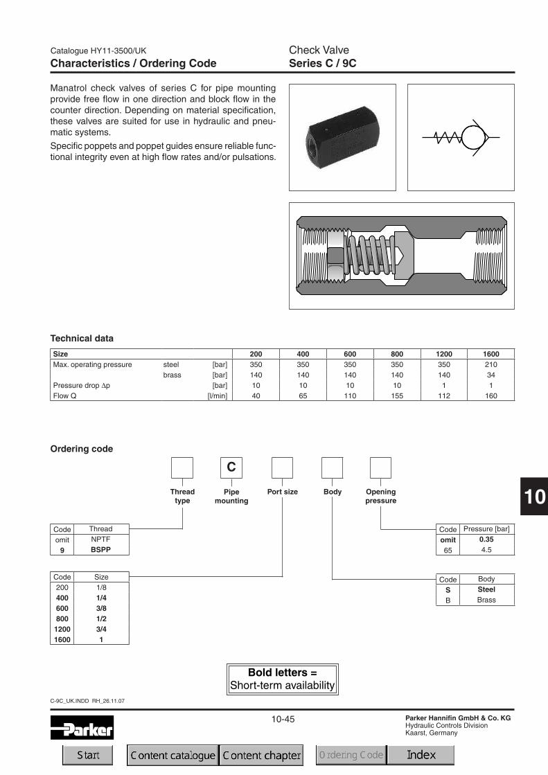
Check ValveSeries C / 9CCharacteristics / Ordering Code
Ordering code
C
Openingpressure
Pipemounting
Port size
Code Pressure [bar]
omit 0.35
65 4.5
Threadtype
Code Thread
omit NPTF
9 BSPP
Code Body
S Steel
B Brass
Body
Manatrol check valves of series C for pipe mountingprovide free flow in one direction and block flow in thecounter direction. Depending on material specification,these valves are suited for use in hydraulic and pneu-matic systems.
Specific poppets and poppet guides ensure reliable func-tional integrity even at high flow rates and/or pulsations.
Technical data
Size 200 400 600 800 1200 1600Max. operating pressure steel [bar] 350 350 350 350 350 210
brass [bar] 140 140 140 140 140 34Pressure drop ∆p [bar] 10 10 10 10 1 1Flow Q [l/min] 40 65 110 155 112 160
Code Size200 1/8400 1/4600 3/8800 1/21200 3/41600 1

10-46
C-9C_UK.INDD RH_26.11.07
Catalogue HY11-3500/UK
Parker Hannifin GmbH & Co. KGHydraulic Controls DivisionKaarst, Germany
10
Check ValveSeries C / 9C
SizeThreaded connection R* Dimensions [mm]
Weight [kg]G thread NPTF thread B L
C 200 R 1/8" 1/8-27 NPTF 16 51 0.05C 400 R 1/4" 1/4-18 NPTF 21 66 0.2C 600 R 3/8" 3/8-18 NPTF 25 70 0.2C 800 R 1/2" 1/2-14 NPTF 32 87 0.6C 1200 R 3/4" 3/4-14 NPTF 38 99 0.9C 1600 R 1" 1-11-1/2 NPTF 45 127 1.5
∆p/Q performance curves
Dimensions
* For alternative thread design, see ordering code.
Characteristic Curves / Dimensions
10-47
Catalogue HY11-3500/UK
Parker Hannifin GmbH & Co. KGHydraulic Controls DivisionKaarst, Germany
10
CP-9CP_UK.INDD RH_26.11.07
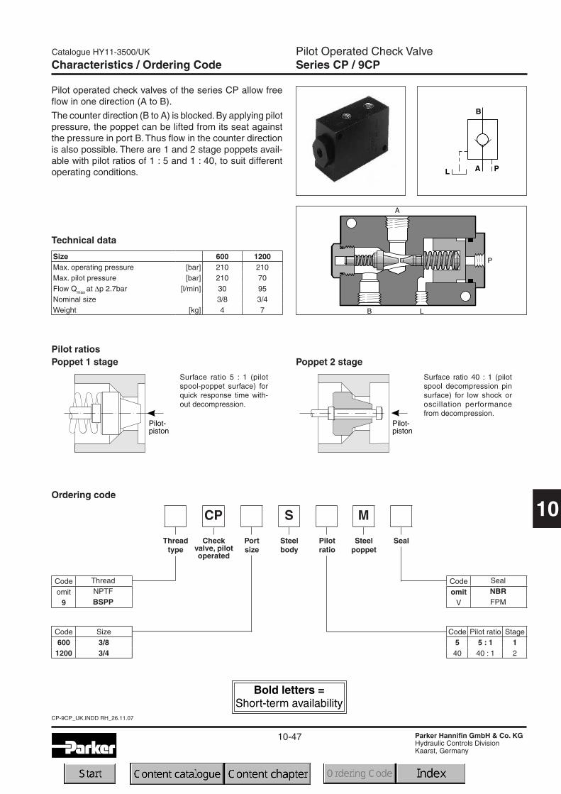
Pilot Operated Check ValveSeries CP / 9CPCharacteristics / Ordering Code
Ordering code
Code Thread
omit NPTF
9 BSPP
Code Pilot ratio Stage5 5 : 1 140 40 : 1 2
Code Size600 3/81200 3/4
Pilot operated check valves of the series CP allow freeflow in one direction (A to B).
The counter direction (B to A) is blocked.By applying pilotpressure, the poppet can be lifted from its seat againstthe pressure in port B. Thus flow in the counter directionis also possible. There are 1 and 2 stage poppets avail-able with pilot ratios of 1 : 5 and 1 : 40, to suit differentoperating conditions.
Pilot ratiosPoppet 1 stage
Surface ratio 5 : 1 (pilotspool-poppet surface) forquick response time with-out decompression.
Surface ratio 40 : 1 (pilotspool decompression pinsurface) for low shock oroscillation performancefrom decompression.
Size 600 1200Max. operating pressure [bar] 210 210Max. pilot pressure [bar] 210 70Flow Qmax at ∆p 2.7bar [l/min] 30 95Nominal size 3/8 3/4Weight [kg] 4 7
Technical data
Poppet 2 stage
SCP M
Steelpoppet
Checkvalve, pilotoperated
Steelbody
Threadtype
Pilotratio
SealPortsize
Code Seal
omit NBR
V FPM

10-48
CP-9CP_UK.INDD RH_26.11.07
Catalogue HY11-3500/UK
Parker Hannifin GmbH & Co. KGHydraulic Controls DivisionKaarst, Germany
10
Pilot Operated Check ValveSeries CP / 9CPCharacteristic Curves / Dimensions
Size A, B L3 B1 B2 H1 H L4 L7 H4 L L1 H2 H3 L6 L5 Ød W9CP600S G3/8 53.3 50.8 25.4 38.1 76.2 25.4 76.2 10.4 120.7 10.7 9.4 66.5 9.4 111 9.1 -
9CP1200S G3/4 63.5 63.5 31.8 50.8 101.6 31.8 91.2 10.7 152.4 11.43 11.2 90.4 11.2 141.2 10.7 7.9
∆p/Q performance curves
The curves refer to hydraulic oil of 33 cSt and 50°C.
Dimensions
10-49
RH_UK.INDD RH_26.11.07
Catalogue HY11-3500/UK
Parker Hannifin GmbH & Co. KGHydraulic Controls DivisionKaarst, Germany
10
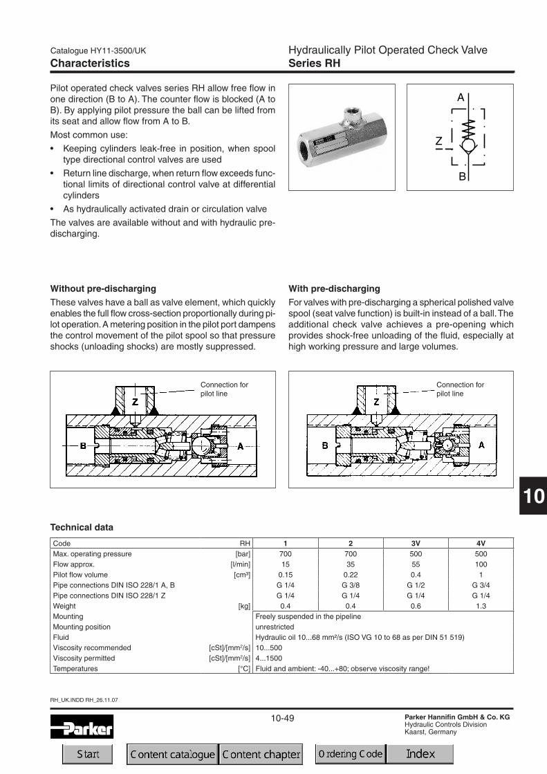
Hydraulically Pilot Operated Check ValveSeries RHCharacteristics
Pilot operated check valves series RH allow free flow inone direction (B to A). The counter flow is blocked (A toB). By applying pilot pressure the ball can be lifted fromits seat and allow flow from A to B.
Most common use:
• Keeping cylinders leak-free in position, when spooltype directional control valves are used
• Return line discharge, when return flow exceeds func-tional limits of directional control valve at differentialcylinders
• As hydraulically activated drain or circulation valve
The valves are available without and with hydraulic pre-discharging.
Without pre-dischargingThese valves have a ball as valve element, which quicklyenables the full flow cross-section proportionally during pi-lot operation.A metering position in the pilot port dampensthe control movement of the pilot spool so that pressureshocks (unloading shocks) are mostly suppressed.
With pre-dischargingFor valves with pre-discharging a spherical polished valvespool (seat valve function) is built-in instead of a ball.Theadditional check valve achieves a pre-opening whichprovides shock-free unloading of the fluid, especially athigh working pressure and large volumes.
Connection forpilot line
Connection forpilot line
Code RH 1 2 3V 4VMax. operating pressure [bar] 700 700 500 500Flow approx. [l/min] 15 35 55 100Pilot flow volume [cm³] 0.15 0.22 0.4 1Pipe connections DIN ISO 228/1 A, B G 1/4 G 3/8 G 1/2 G 3/4Pipe connections DIN ISO 228/1 Z G 1/4 G 1/4 G 1/4 G 1/4Weight [kg] 0.4 0.4 0.6 1.3Mounting Freely suspended in the pipelineMounting position unrestrictedFluid Hydraulic oil 10...68 mm²/s (ISO VG 10 to 68 as per DIN 51 519)Viscosity recommended [cSt]/[mm2/s] 10...500Viscosity permitted [cSt]/[mm2/s] 4...1500Temperatures [°C] Fluid and ambient: -40...+80; observe viscosity range!
Technical data
10-50
RH_UK.INDD RH_26.11.07
Catalogue HY11-3500/UK
Parker Hannifin GmbH & Co. KGHydraulic Controls DivisionKaarst, Germany
10
Hydraulically Pilot Operated Check ValveSeries RH
* only for sizes 3 and 4
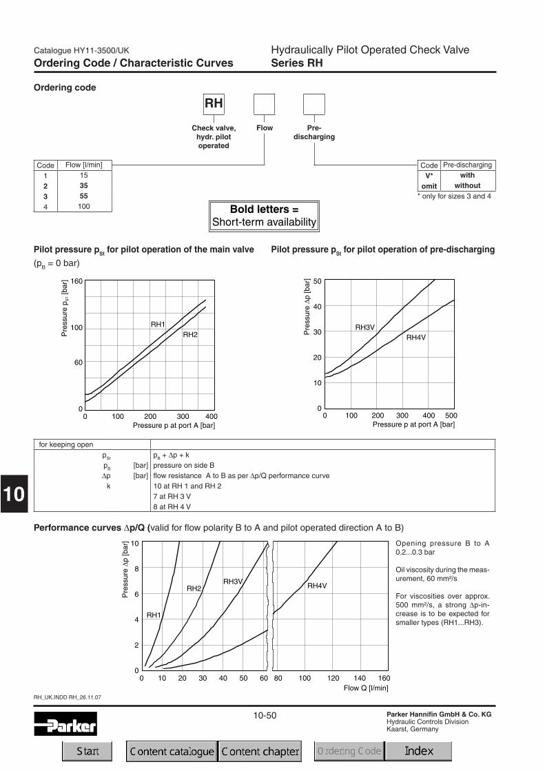
Performance curves ∆p/Q (valid for flow polarity B to A and pilot operated direction A to B)
Opening pressure B to A0.2...0.3 bar
Oil viscosity during the meas-urement, 60 mm²/s
For viscosities over approx.500 mm²/s, a strong ∆p-in-crease is to be expected forsmaller types (RH1...RH3).
Pilot pressure pSt for pilot operation of the main valve(pB = 0 bar)
Pilot pressure pSt for pilot operation of pre-discharging
Ordering Code / Characteristic Curves
Ordering code
RH
Check valve,hydr. pilotoperated
Flow
Code Pre-discharging
V* with
omit without
Code Flow [l/min]
1 15
2 35
3 55
4 100
Pre-discharging
for keeping openpSt pB + ∆p + kpB [bar] pressure on side B∆p [bar] flow resistance A to B as per ∆p/Q performance curve
k 10 at RH 1 and RH 27 at RH 3 V8 at RH 4 V
10-51
RH_UK.INDD RH_26.11.07
Catalogue HY11-3500/UK
Parker Hannifin GmbH & Co. KGHydraulic Controls DivisionKaarst, Germany
10
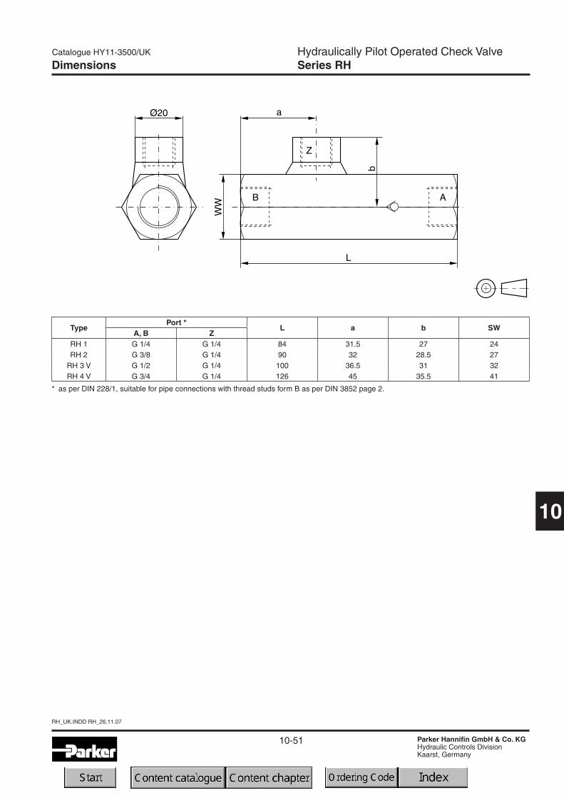
Hydraulically Pilot Operated Check ValveSeries RHDimensions
TypePort *
L a b SWA, B Z
RH 1 G 1/4 G 1/4 84 31.5 27 24RH 2 G 3/8 G 1/4 90 32 28.5 27
RH 3 V G 1/2 G 1/4 100 36.5 31 32RH 4 V G 3/4 G 1/4 126 45 35.5 41
* as per DIN 228/1, suitable for pipe connections with thread studs form B as per DIN 3852 page 2.

10-52
RH_UK.INDD RH_26.11.07
Catalogue HY11-3500/UK
Parker Hannifin GmbH & Co. KGHydraulic Controls DivisionKaarst, Germany
10
Notes
Catalogue HY11-3500/UK
Parker Hannifin GmbH & Co. KGHydraulic Controls DivisionKaarst, Germany
access10.INDD RH_26.11.07
10-53
10
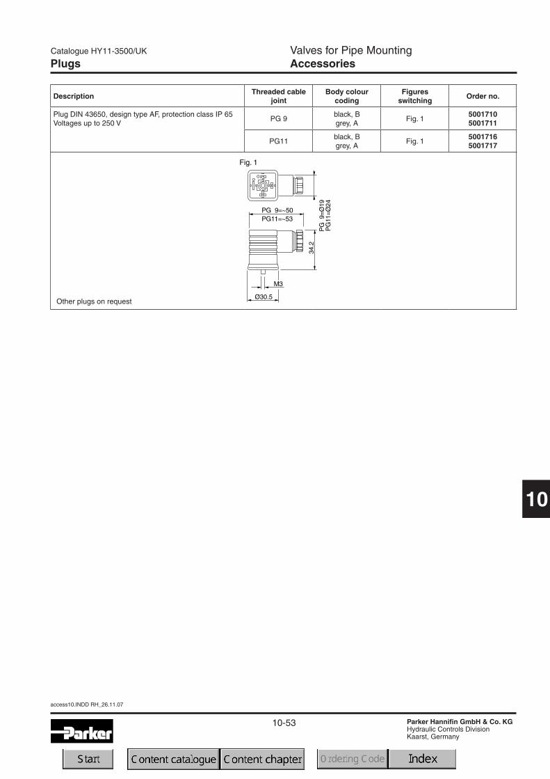
Valves for Pipe MountingAccessoriesPlugs
DescriptionThreaded cable
jointBody colour
codingFigures
switchingOrder no.
Plug DIN 43650, design type AF, protection class IP 65Voltages up to 250 V
PG 9black, Bgrey, A
Fig. 150017105001711
PG11black, Bgrey, A
Fig. 150017165001717
Other plugs on request
access10.INDD RH_26.11.07
Catalogue HY11-3500/UK
Parker Hannifin GmbH & Co. KGHydraulic Controls DivisionKaarst, Germany
10-54
10
Notes