chapter 10 acceptance tests and commissioning measurements€¦ · acceptance tests and...
TRANSCRIPT

1
IAEAInternational Atomic Energy Agency
This set of 189 slides is based on Chapter 10 authored by
J. L. Horton
of the IAEA publication (ISBN 92-0-107304-6):
Radiation Oncology Physics:
A Handbook for Teachers and Students
Objective:
To familiarize students with the series of tasks and measurements
required to place a radiation therapy machine into clinical operation.
Chapter 10
Acceptance Tests and Commissioning
Measurements
Slide set prepared in 2006 (updated Aug2007)
by G.H. Hartmann (DKFZ, Heidelberg)
Comments to S. Vatnitsky:
IAEA Review of Radiation Oncology Physics: A Handbook for Teachers and Students - 10.(2/189)
10.1 Introduction
10.2 Measurement Equipment
10.3 Acceptance Tests
10.4 Commissioning
10.5 Time Requirements
CHAPTER 10. TABLE OF CONTENTS
2
IAEA Review of Radiation Oncology Physics: A Handbook for Teachers and Students - 10.1 Slide 1 (3/189)
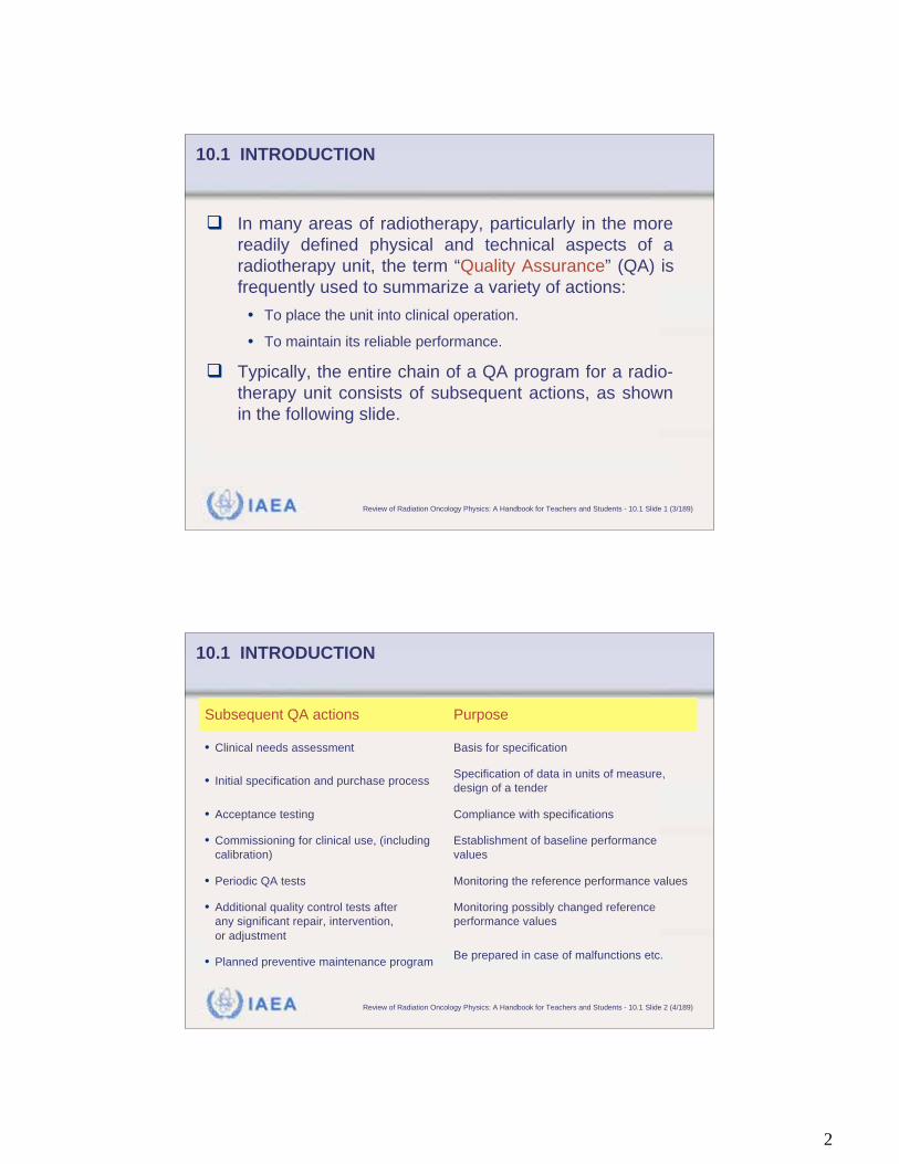
10.1 INTRODUCTION
In many areas of radiotherapy, particularly in the more
readily defined physical and technical aspects of a
radiotherapy unit, the term “Quality Assurance” (QA) is
frequently used to summarize a variety of actions:
• To place the unit into clinical operation.
• To maintain its reliable performance.
Typically, the entire chain of a QA program for a radio-
therapy unit consists of subsequent actions, as shown
in the following slide.
IAEA Review of Radiation Oncology Physics: A Handbook for Teachers and Students - 10.1 Slide 2 (4/189)
Be prepared in case of malfunctions etc.• Planned preventive maintenance program
Monitoring possibly changed reference
performance values
• Additional quality control tests after
any significant repair, intervention,
or adjustment
Monitoring the reference performance values• Periodic QA tests
Establishment of baseline performance
values
• Commissioning for clinical use, (including
calibration)
Compliance with specifications• Acceptance testing
Specification of data in units of measure,
design of a tender• Initial specification and purchase process
Basis for specification• Clinical needs assessment
PurposeSubsequent QA actions
10.1 INTRODUCTION

3
IAEA Review of Radiation Oncology Physics: A Handbook for Teachers and Students - 10.1 Slide 3 (5/189)
Acceptance tests and commissioning constitute a major
part in this QA program for radiotherapy.
This chapter is focusing on the duties of acceptance
testing and commissioning.
Although calibrations of the treatment beams are a part of
the acceptance tests and commissioning, calibration will
not be discussed in this chapter since it is fully covered in
Chapter 9.
10.1 INTRODUCTION
IAEA Review of Radiation Oncology Physics: A Handbook for Teachers and Students - 10.2 Slide 1 (6/189)
10.2 MEASUREMENT EQUIPMENT
Acceptance tests and commissioning can be performed
only if adequate measurement equipment is available:
Radiation survey equipment:
• Geiger counter
• Large volume ionization chamber survey meter
• Neutron survey meter (if the unit operates above 10 MeV)
Ionometric dosimetry equipment
Other dosimetric detectors (film, diodes)
Phantoms
• Radiation field analyzer and water phantom
• Plastic phantoms
4
IAEA Review of Radiation Oncology Physics: A Handbook for Teachers and Students - 10.2.1 Slide 1 (7/189)
10.2 MEASUREMENT EQUIPMENT
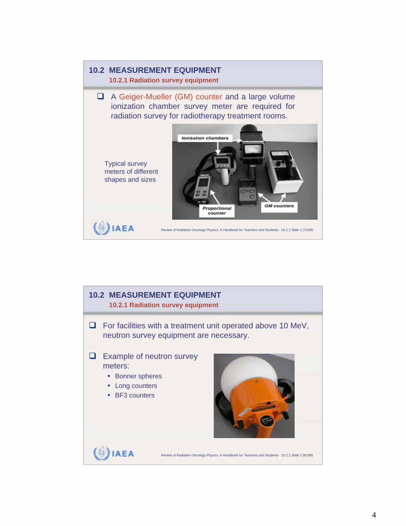
10.2.1 Radiation survey equipment
A Geiger-Mueller (GM) counter and a large volume
ionization chamber survey meter are required for
radiation survey for radiotherapy treatment rooms.
Typical survey
meters of different
shapes and sizes
IAEA Review of Radiation Oncology Physics: A Handbook for Teachers and Students - 10.2.1 Slide 2 (8/189)
10.2 MEASUREMENT EQUIPMENT
10.2.1 Radiation survey equipment
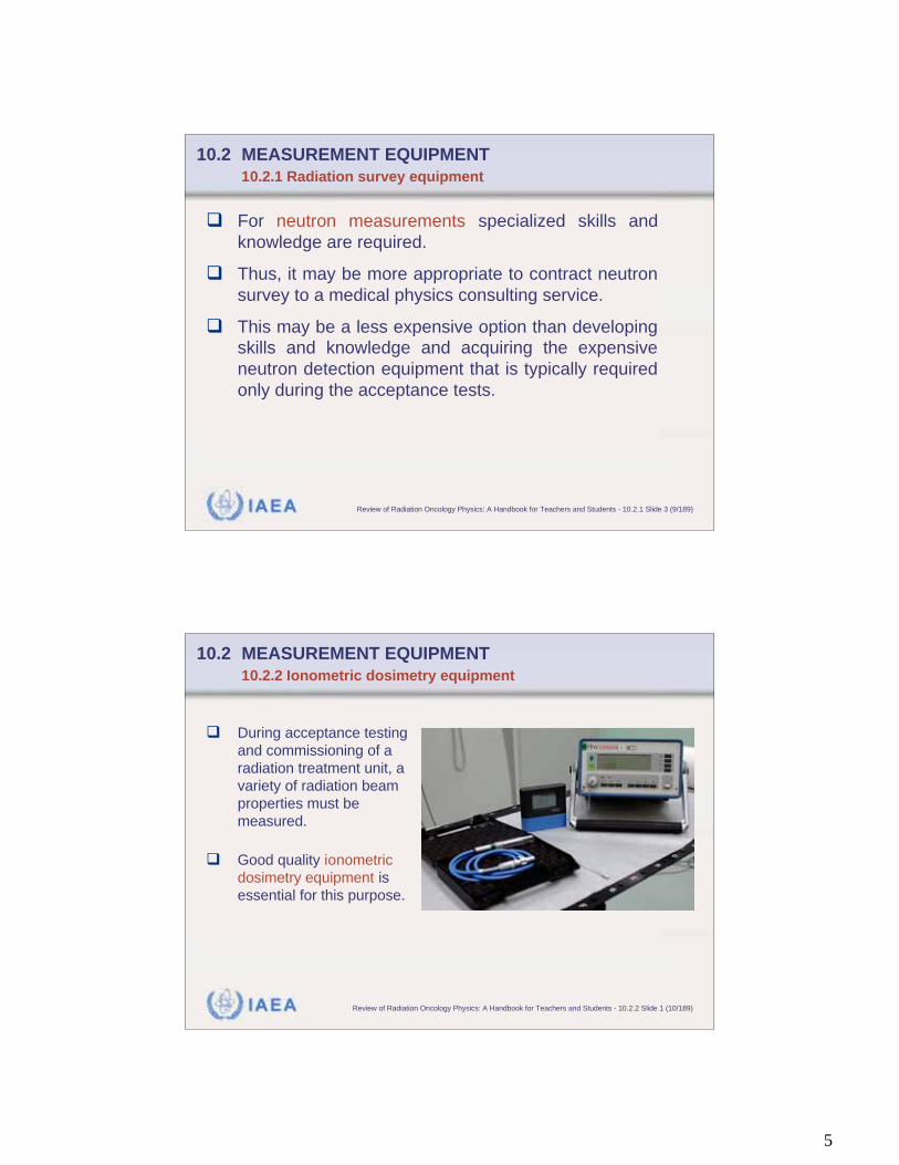
For facilities with a treatment unit operated above 10 MeV,
neutron survey equipment are necessary.
Example of neutron survey
meters:
• Bonner spheres
• Long counters
• BF3 counters
5
IAEA Review of Radiation Oncology Physics: A Handbook for Teachers and Students - 10.2.1 Slide 3 (9/189)
For neutron measurements specialized skills and
knowledge are required.
Thus, it may be more appropriate to contract neutron
survey to a medical physics consulting service.
This may be a less expensive option than developing
skills and knowledge and acquiring the expensive
neutron detection equipment that is typically required
only during the acceptance tests.
10.2 MEASUREMENT EQUIPMENT
10.2.1 Radiation survey equipment
IAEA Review of Radiation Oncology Physics: A Handbook for Teachers and Students - 10.2.2 Slide 1 (10/189)
10.2 MEASUREMENT EQUIPMENT
10.2.2 Ionometric dosimetry equipment
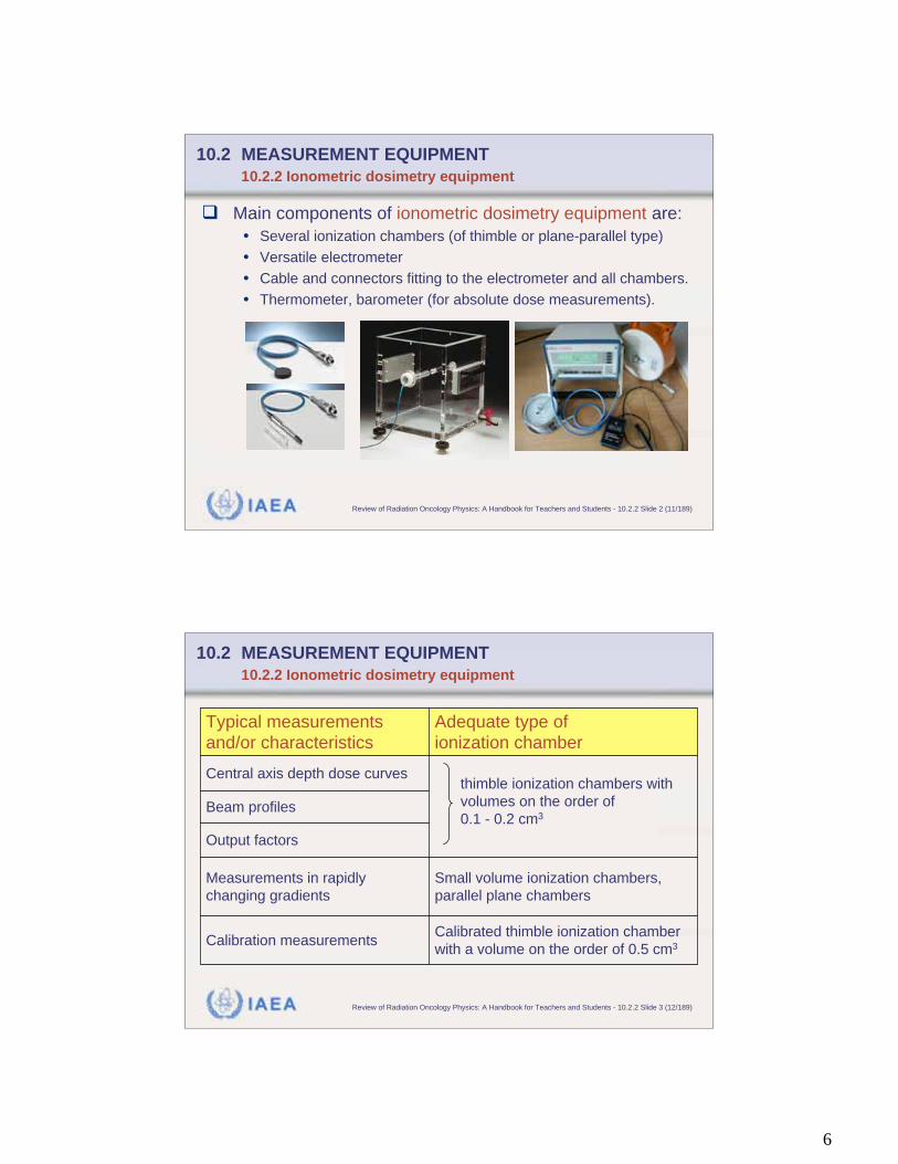
During acceptance testing
and commissioning of a
radiation treatment unit, a
variety of radiation beam
properties must be
measured.
Good quality ionometric
dosimetry equipment is
essential for this purpose.
6
IAEA Review of Radiation Oncology Physics: A Handbook for Teachers and Students - 10.2.2 Slide 2 (11/189)
Main components of ionometric dosimetry equipment are:
• Several ionization chambers (of thimble or plane-parallel type)
• Versatile electrometer
• Cable and connectors fitting to the electrometer and all chambers.
• Thermometer, barometer (for absolute dose measurements).
10.2 MEASUREMENT EQUIPMENT
10.2.2 Ionometric dosimetry equipment
IAEA Review of Radiation Oncology Physics: A Handbook for Teachers and Students - 10.2.2 Slide 3 (12/189)
Calibrated thimble ionization chamber
with a volume on the order of 0.5 cm3Calibration measurements
Small volume ionization chambers,
parallel plane chambers
Measurements in rapidly
changing gradients
Output factors
Beam profiles
thimble ionization chambers with
volumes on the order of
0.1 - 0.2 cm3
Central axis depth dose curves
Adequate type of
ionization chamber
Typical measurements
and/or characteristics
10.2 MEASUREMENT EQUIPMENT
10.2.2 Ionometric dosimetry equipment
7
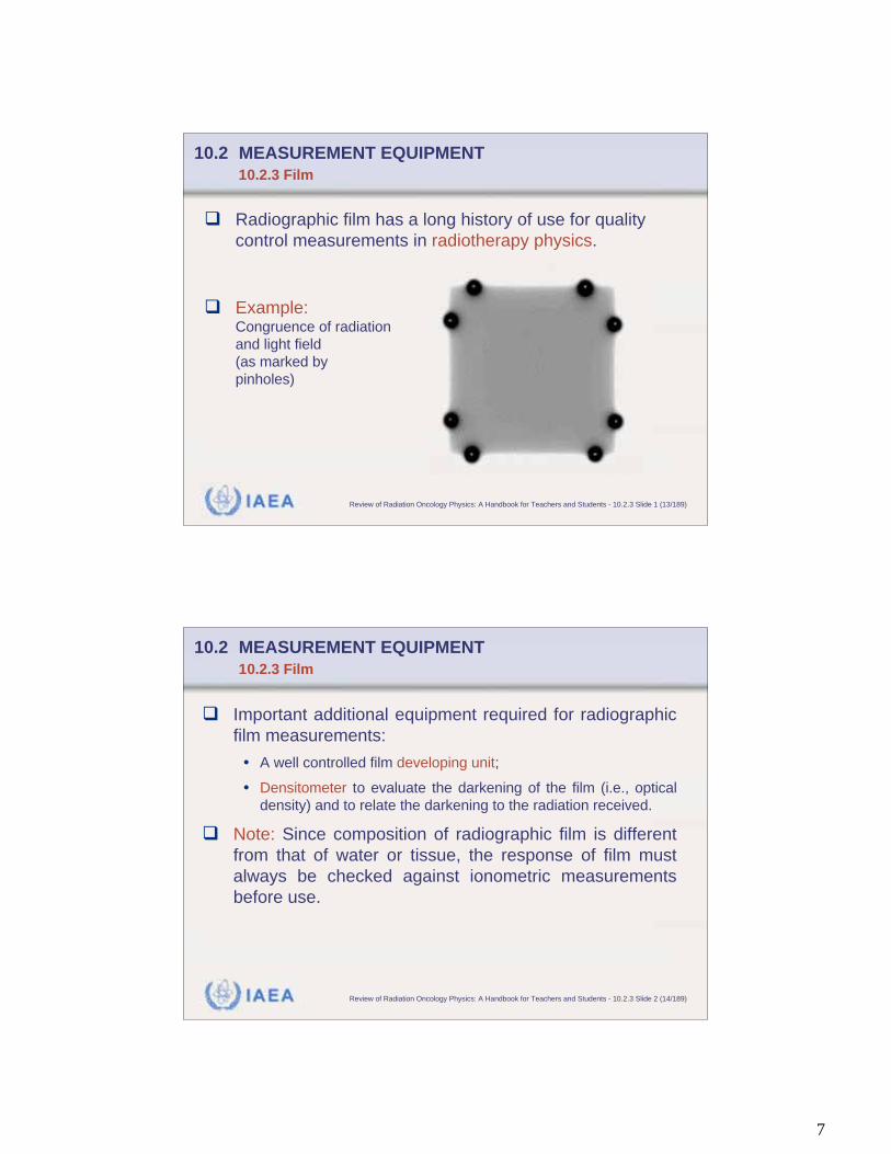
IAEA Review of Radiation Oncology Physics: A Handbook for Teachers and Students - 10.2.3 Slide 1 (13/189)
10.2 MEASUREMENT EQUIPMENT
10.2.3 Film
Radiographic film has a long history of use for quality
control measurements in radiotherapy physics.
Example:Congruence of radiation
and light field
(as marked by
pinholes)
IAEA Review of Radiation Oncology Physics: A Handbook for Teachers and Students - 10.2.3 Slide 2 (14/189)
Important additional equipment required for radiographic
film measurements:
• A well controlled film developing unit;
• Densitometer to evaluate the darkening of the film (i.e., optical
density) and to relate the darkening to the radiation received.
Note: Since composition of radiographic film is different
from that of water or tissue, the response of film must
always be checked against ionometric measurements
before use.
10.2 MEASUREMENT EQUIPMENT
10.2.3 Film
8
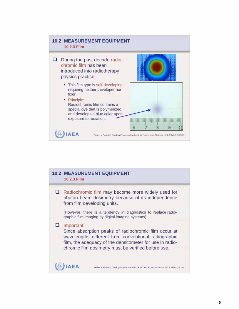
IAEA Review of Radiation Oncology Physics: A Handbook for Teachers and Students - 10.2.3 Slide 3 (15/189)
During the past decade radio-
chromic film has been
introduced into radiotherapy
physics practice.
• This film type is self-developing,
requiring neither developer nor
fixer.
• Principle:
Radiochromic film contains a
special dye that is polymerized
and develops a blue color upon
exposure to radiation.
10.2 MEASUREMENT EQUIPMENT
10.2.3 Film
IAEA Review of Radiation Oncology Physics: A Handbook for Teachers and Students - 10.2.3 Slide 4 (16/189)
Radiochromic film may become more widely used for
photon beam dosimetry because of its independence
from film developing units.
(However, there is a tendency in diagnostics to replace radio-
graphic film imaging by digital imaging systems).
Important:
Since absorption peaks of radiochromic film occur at
wavelengths different from conventional radiographic
film, the adequacy of the densitometer for use in radio-
chromic film dosimetry must be verified before use.
10.2 MEASUREMENT EQUIPMENT
10.2.3 Film
9
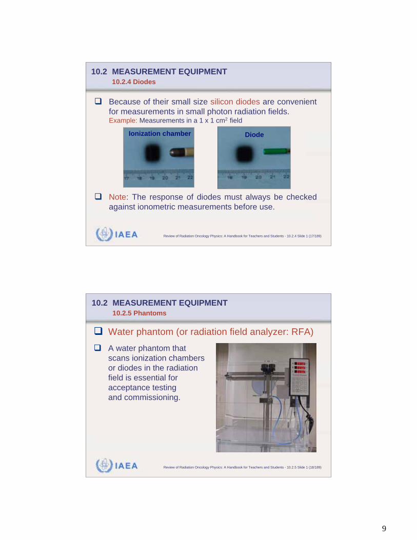
IAEA Review of Radiation Oncology Physics: A Handbook for Teachers and Students - 10.2.4 Slide 1 (17/189)
10.2 MEASUREMENT EQUIPMENT
10.2.4 Diodes
Because of their small size silicon diodes are convenient
for measurements in small photon radiation fields.Example: Measurements in a 1 x 1 cm2 field
Note: The response of diodes must always be checked
against ionometric measurements before use.
Ionization chamber Diode
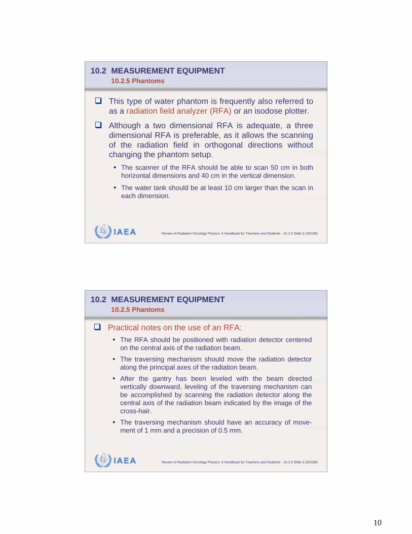
IAEA Review of Radiation Oncology Physics: A Handbook for Teachers and Students - 10.2.5 Slide 1 (18/189)
10.2 MEASUREMENT EQUIPMENT
10.2.5 Phantoms
Water phantom (or radiation field analyzer: RFA)
A water phantom that
scans ionization chambers
or diodes in the radiation
field is essential for
acceptance testing
and commissioning.
10
IAEA Review of Radiation Oncology Physics: A Handbook for Teachers and Students - 10.2.5 Slide 2 (19/189)
This type of water phantom is frequently also referred to
as a radiation field analyzer (RFA) or an isodose plotter.
Although a two dimensional RFA is adequate, a three
dimensional RFA is preferable, as it allows the scanning
of the radiation field in orthogonal directions without
changing the phantom setup.
• The scanner of the RFA should be able to scan 50 cm in both
horizontal dimensions and 40 cm in the vertical dimension.
• The water tank should be at least 10 cm larger than the scan in
each dimension.
10.2 MEASUREMENT EQUIPMENT
10.2.5 Phantoms
IAEA Review of Radiation Oncology Physics: A Handbook for Teachers and Students - 10.2.5 Slide 3 (20/189)
Practical notes on the use of an RFA:
• The RFA should be positioned with radiation detector centered
on the central axis of the radiation beam.
• The traversing mechanism should move the radiation detector
along the principal axes of the radiation beam.
• After the gantry has been leveled with the beam directed
vertically downward, leveling of the traversing mechanism can
be accomplished by scanning the radiation detector along the
central axis of the radiation beam indicated by the image of the
cross-hair.
• The traversing mechanism should have an accuracy of move-
ment of 1 mm and a precision of 0.5 mm.
10.2 MEASUREMENT EQUIPMENT
10.2.5 Phantoms
11
IAEA Review of Radiation Oncology Physics: A Handbook for Teachers and Students - 10.2.5 Slide 4 (21/189)
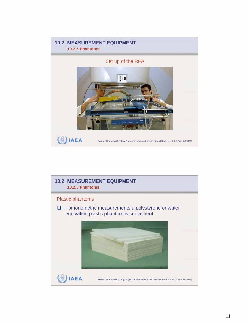
Set up of the RFA
10.2 MEASUREMENT EQUIPMENT
10.2.5 Phantoms
IAEA Review of Radiation Oncology Physics: A Handbook for Teachers and Students - 10.2.5 Slide 5 (22/189)
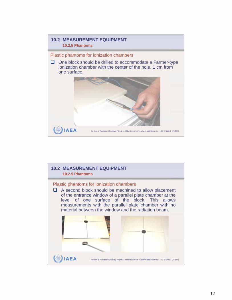
Plastic phantoms
For ionometric measurements a polystyrene or water
equivalent plastic phantom is convenient.
10.2 MEASUREMENT EQUIPMENT
10.2.5 Phantoms
12
IAEA Review of Radiation Oncology Physics: A Handbook for Teachers and Students - 10.2.5 Slide 6 (23/189)
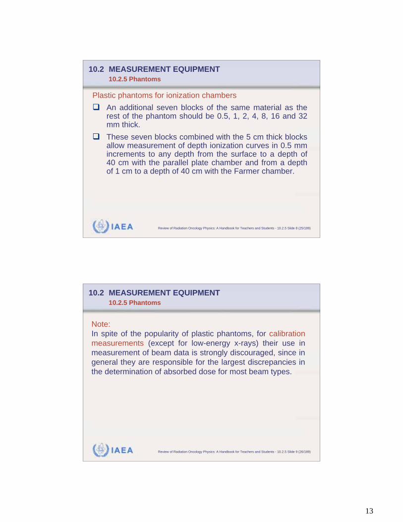
Plastic phantoms for ionization chambers
One block should be drilled to accommodate a Farmer-typeionization chamber with the center of the hole, 1 cm fromone surface.
10.2 MEASUREMENT EQUIPMENT
10.2.5 Phantoms
IAEA Review of Radiation Oncology Physics: A Handbook for Teachers and Students - 10.2.5 Slide 7 (24/189)
Plastic phantoms for ionization chambers
A second block should be machined to allow placementof the entrance window of a parallel plate chamber at thelevel of one surface of the block. This allowsmeasurements with the parallel plate chamber with nomaterial between the window and the radiation beam.
10.2 MEASUREMENT EQUIPMENT
10.2.5 Phantoms
13
IAEA Review of Radiation Oncology Physics: A Handbook for Teachers and Students - 10.2.5 Slide 8 (25/189)
Plastic phantoms for ionization chambers
An additional seven blocks of the same material as therest of the phantom should be 0.5, 1, 2, 4, 8, 16 and 32mm thick.
These seven blocks combined with the 5 cm thick blocksallow measurement of depth ionization curves in 0.5 mmincrements to any depth from the surface to a depth of40 cm with the parallel plate chamber and from a depthof 1 cm to a depth of 40 cm with the Farmer chamber.
10.2 MEASUREMENT EQUIPMENT
10.2.5 Phantoms
IAEA Review of Radiation Oncology Physics: A Handbook for Teachers and Students - 10.2.5 Slide 9 (26/189)
Note:
In spite of the popularity of plastic phantoms, for calibration
measurements (except for low-energy x-rays) their use in
measurement of beam data is strongly discouraged, since in
general they are responsible for the largest discrepancies in
the determination of absorbed dose for most beam types.
10.2 MEASUREMENT EQUIPMENT
10.2.5 Phantoms
14
IAEA Review of Radiation Oncology Physics: A Handbook for Teachers and Students - 10.2.5 Slide 10 (27/189)
Plastic phantoms for films
A plastic phantom is also useful for film dosimetry.
It is convenient to design one section of the phantom to
serve as a film cassette. Other phantom sections can be
placed adjacent to the cassette holder to provide full
scattering conditions.
10.2 MEASUREMENT EQUIPMENT
10.2.5 Phantoms
IAEA Review of Radiation Oncology Physics: A Handbook for Teachers and Students - 10.2.5 Slide 11 (28/189)
Practical notes on use of plastic phantoms for film dosimetry:
Use of ready pack film irradiated parallel to the central axis of the
beam requires that the edge of the film be placed at the surface of
the phantom and that the excess paper be folded down and
secured to the entrance surface of the phantom.
Pinholes should be placed in a corner of the downstream edge of
the paper package so that air can be squeezed out before placing
the ready pack into the phantom. Otherwise air bubbles will be
trapped between the film and the paper. Radiation will be
transmitted un-attenuated through these air bubbles producing
incorrect data.
10.2 MEASUREMENT EQUIPMENT
10.2.5 Phantoms
15
IAEA Review of Radiation Oncology Physics: A Handbook for Teachers and Students - 10.3 Slide 1 (29/189)
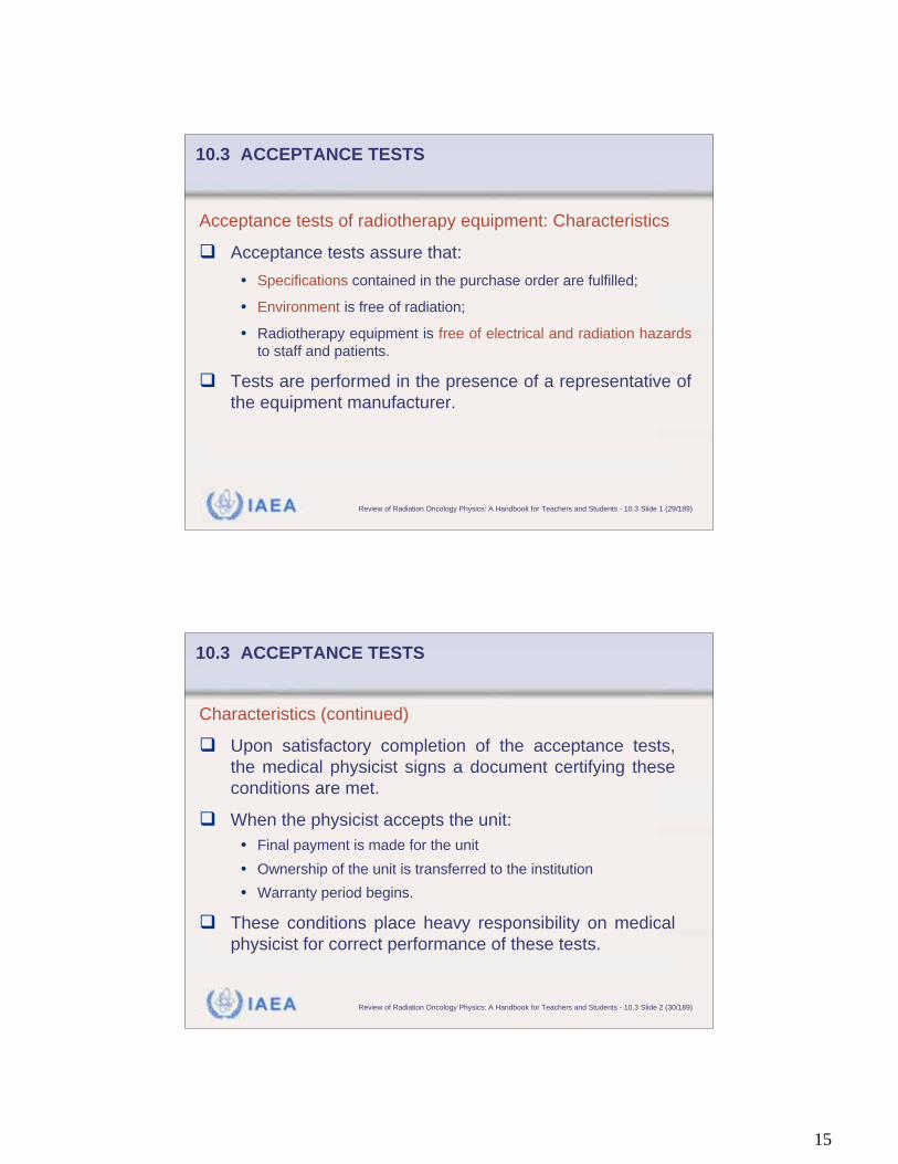
10.3 ACCEPTANCE TESTS
Acceptance tests of radiotherapy equipment: Characteristics
Acceptance tests assure that:
• Specifications contained in the purchase order are fulfilled;
• Environment is free of radiation;
• Radiotherapy equipment is free of electrical and radiation hazards
to staff and patients.
Tests are performed in the presence of a representative of
the equipment manufacturer.
IAEA Review of Radiation Oncology Physics: A Handbook for Teachers and Students - 10.3 Slide 2 (30/189)
Characteristics (continued)
Upon satisfactory completion of the acceptance tests,
the medical physicist signs a document certifying these
conditions are met.
When the physicist accepts the unit:
• Final payment is made for the unit
• Ownership of the unit is transferred to the institution
• Warranty period begins.
These conditions place heavy responsibility on medical
physicist for correct performance of these tests.
10.3 ACCEPTANCE TESTS
16
IAEA Review of Radiation Oncology Physics: A Handbook for Teachers and Students - 10.3 Slide 3 (31/189)
Acceptance tests are generally divided into three groups:
• Safety checks
• Mechanical checks
• Dosimetry measurements
A number of national and international protocols exist to
guide the physicist in the performance of acceptance tests.
For example:
Comprehensive QA for Radiation Oncology, AAPM Task Group 40.
10.3 ACCEPTANCE TESTS
IAEA Review of Radiation Oncology Physics: A Handbook for Teachers and Students - 10.3.1 Slide 1 (32/189)
10.3 ACCEPTANCE TESTS
10.3.1 Safety Checks
Safety checks include verification of the following components:
Interlocks.
Warning lights.
Patient monitoring equipment.
Radiation survey.
Collimator and head leakage.
17
IAEA Review of Radiation Oncology Physics: A Handbook for Teachers and Students - 10.3.1 Slide 2 (33/189)
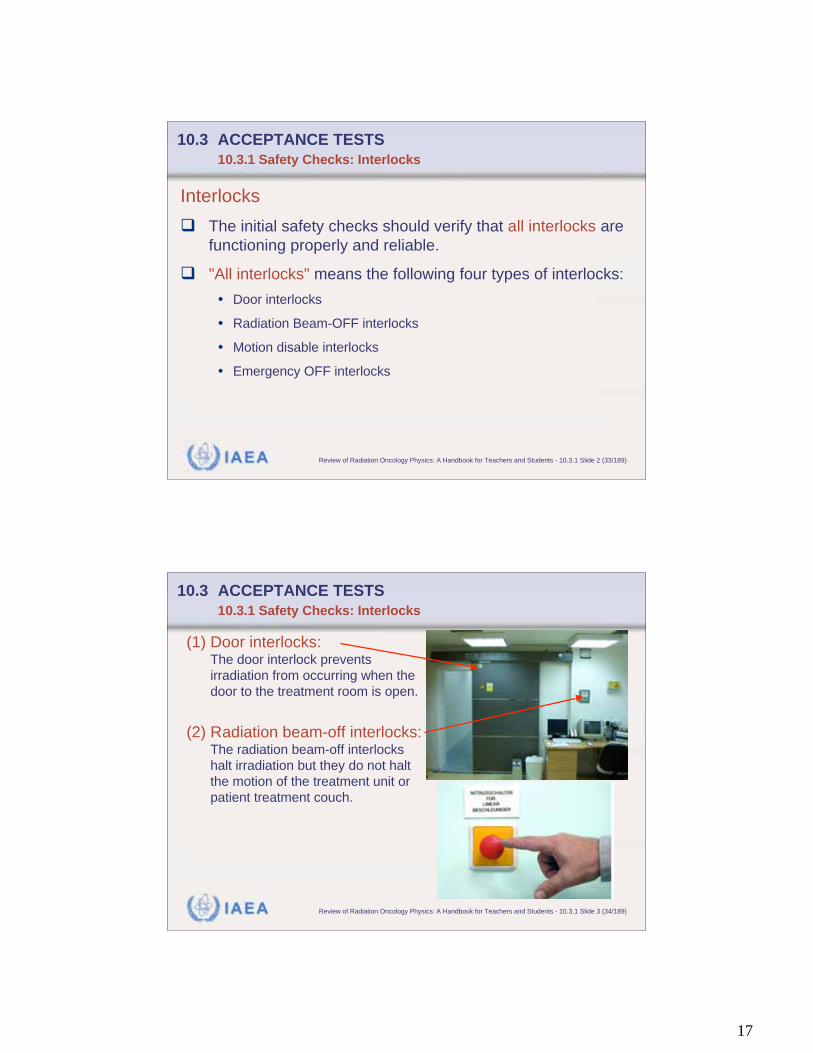
10.3 ACCEPTANCE TESTS
10.3.1 Safety Checks: Interlocks
Interlocks
The initial safety checks should verify that all interlocks are
functioning properly and reliable.
"All interlocks" means the following four types of interlocks:
• Door interlocks
• Radiation Beam-OFF interlocks
• Motion disable interlocks
• Emergency OFF interlocks
IAEA Review of Radiation Oncology Physics: A Handbook for Teachers and Students - 10.3.1 Slide 3 (34/189)
(1) Door interlocks:The door interlock prevents
irradiation from occurring when the
door to the treatment room is open.
(2) Radiation beam-off interlocks:The radiation beam-off interlocks
halt irradiation but they do not halt
the motion of the treatment unit or
patient treatment couch.
10.3 ACCEPTANCE TESTS
10.3.1 Safety Checks: Interlocks
18
IAEA Review of Radiation Oncology Physics: A Handbook for Teachers and Students - 10.3.1 Slide 4 (35/189)
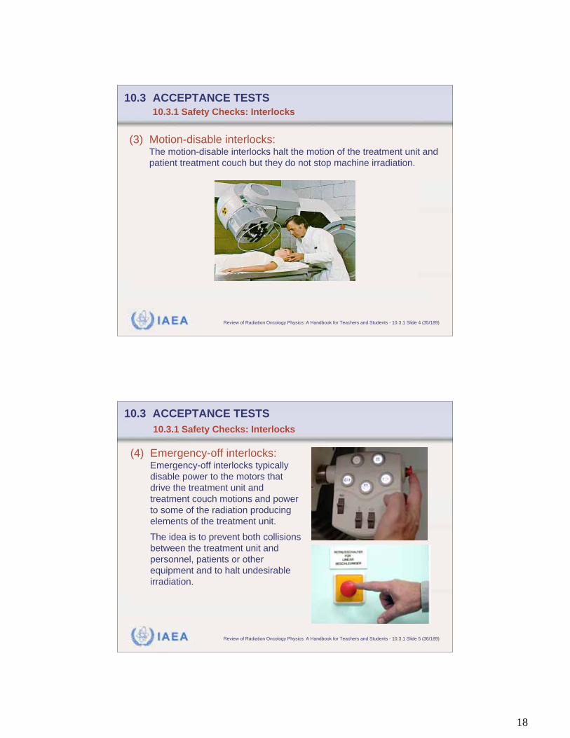
(3) Motion-disable interlocks:The motion-disable interlocks halt the motion of the treatment unit and
patient treatment couch but they do not stop machine irradiation.
10.3 ACCEPTANCE TESTS
10.3.1 Safety Checks: Interlocks
IAEA Review of Radiation Oncology Physics: A Handbook for Teachers and Students - 10.3.1 Slide 5 (36/189)
(4) Emergency-off interlocks:Emergency-off interlocks typically
disable power to the motors that
drive the treatment unit and
treatment couch motions and power
to some of the radiation producing
elements of the treatment unit.
The idea is to prevent both collisions
between the treatment unit and
personnel, patients or other
equipment and to halt undesirable
irradiation.
10.3 ACCEPTANCE TESTS
10.3.1 Safety Checks: Interlocks
19
IAEA Review of Radiation Oncology Physics: A Handbook for Teachers and Students - 10.3.1 Slide 6 (37/189)
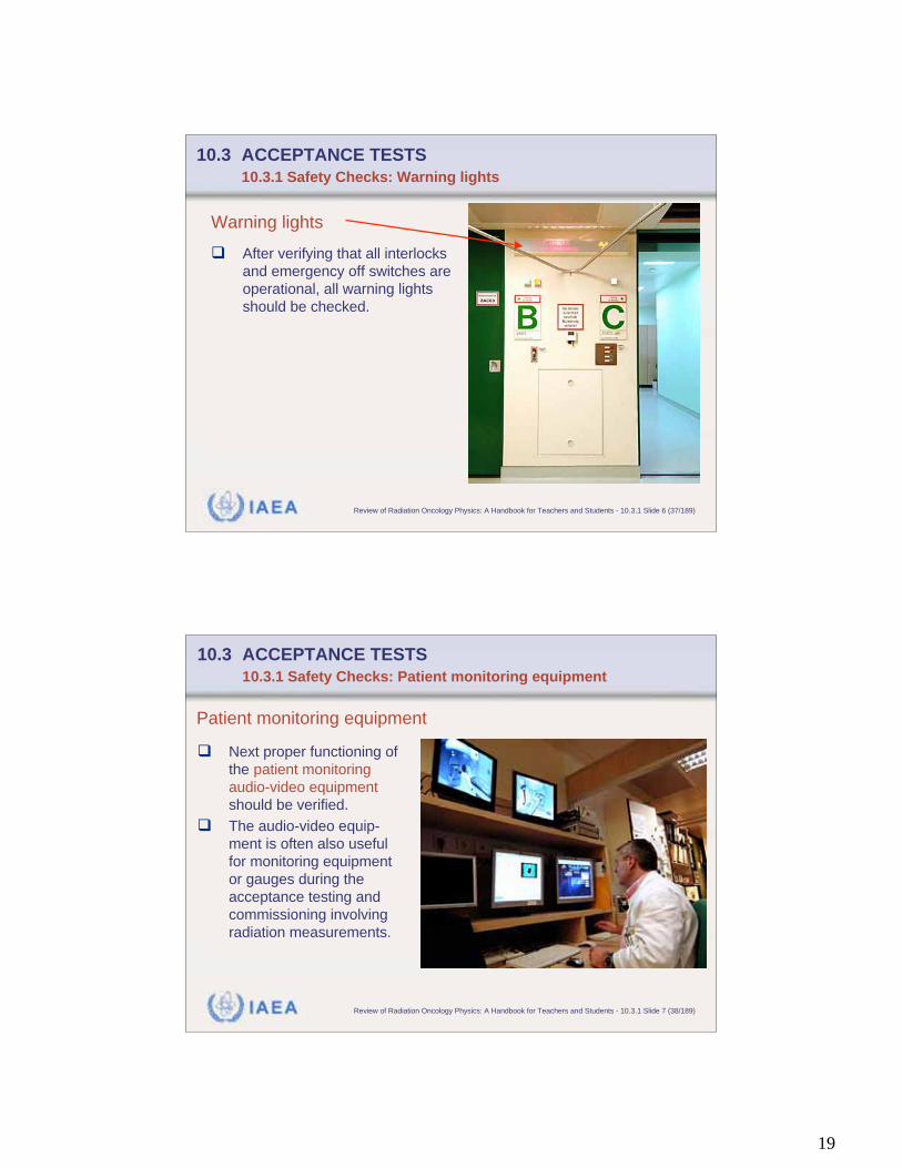
10.3 ACCEPTANCE TESTS
10.3.1 Safety Checks: Warning lights
Warning lights
After verifying that all interlocks
and emergency off switches are
operational, all warning lights
should be checked.
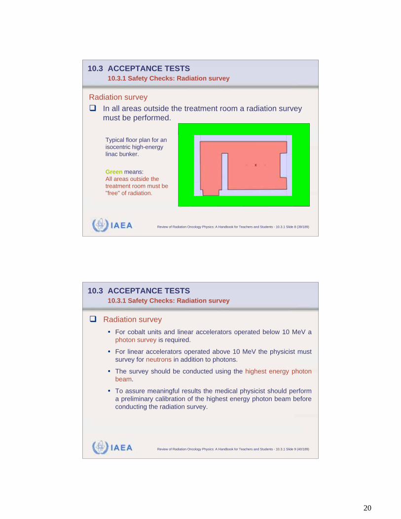
IAEA Review of Radiation Oncology Physics: A Handbook for Teachers and Students - 10.3.1 Slide 7 (38/189)
10.3 ACCEPTANCE TESTS
10.3.1 Safety Checks: Patient monitoring equipment
Next proper functioning of
the patient monitoring
audio-video equipment
should be verified.
The audio-video equip-
ment is often also useful
for monitoring equipment
or gauges during the
acceptance testing and
commissioning involving
radiation measurements.
Patient monitoring equipment
20
IAEA Review of Radiation Oncology Physics: A Handbook for Teachers and Students - 10.3.1 Slide 8 (39/189)
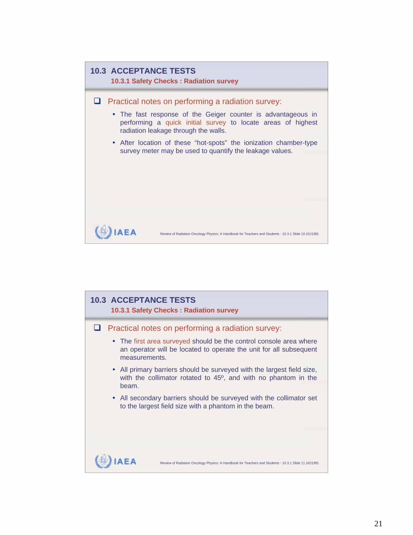
10.3 ACCEPTANCE TESTS
10.3.1 Safety Checks: Radiation survey
Radiation survey
In all areas outside the treatment room a radiation survey
must be performed.
Typical floor plan for an
isocentric high-energy
linac bunker.
Green means:
All areas outside the
treatment room must be
"free" of radiation.
X
IAEA Review of Radiation Oncology Physics: A Handbook for Teachers and Students - 10.3.1 Slide 9 (40/189)
10.3 ACCEPTANCE TESTS
10.3.1 Safety Checks: Radiation survey
Radiation survey
• For cobalt units and linear accelerators operated below 10 MeV a
photon survey is required.
• For linear accelerators operated above 10 MeV the physicist must
survey for neutrons in addition to photons.
• The survey should be conducted using the highest energy photon
beam.
• To assure meaningful results the medical physicist should perform
a preliminary calibration of the highest energy photon beam before
conducting the radiation survey.
21
IAEA Review of Radiation Oncology Physics: A Handbook for Teachers and Students - 10.3.1 Slide 10 (41/189)
10.3 ACCEPTANCE TESTS
10.3.1 Safety Checks : Radiation survey
Practical notes on performing a radiation survey:
• The fast response of the Geiger counter is advantageous in
performing a quick initial survey to locate areas of highest
radiation leakage through the walls.
• After location of these “hot-spots” the ionization chamber-type
survey meter may be used to quantify the leakage values.
IAEA Review of Radiation Oncology Physics: A Handbook for Teachers and Students - 10.3.1 Slide 11 (42/189)
10.3 ACCEPTANCE TESTS
10.3.1 Safety Checks : Radiation survey
Practical notes on performing a radiation survey:
• The first area surveyed should be the control console area where
an operator will be located to operate the unit for all subsequent
measurements.
• All primary barriers should be surveyed with the largest field size,
with the collimator rotated to 45º, and with no phantom in the
beam.
• All secondary barriers should be surveyed with the collimator set
to the largest field size with a phantom in the beam.
22
IAEA Review of Radiation Oncology Physics: A Handbook for Teachers and Students - 10.3.1 Slide 12 (43/189)
10.3 ACCEPTANCE TESTS
10.3.1 Safety Checks: Collimator and head leakage
Head leakage
• The source on a cobalt-60 unit or the target on a linear
accelerator are surrounded by shielding.
• Most regulations require this shielding to limit the leakage
radiation to no more than 0.1% of the useful beam at one metre
from the source.
• Adequacy of this shielding must be verified during acceptance
testing.
IAEA Review of Radiation Oncology Physics: A Handbook for Teachers and Students - 10.3.1 Slide 13 (44/189)
10.3 ACCEPTANCE TESTS 10.3.1 Safety Checks: Collimator and head leakage
Practical notes on performing a head leakage test: Use of
film – ionization chamber combination
• The leakage test may be accomplished by closing the collimator
jaws and covering the head of the treatment unit with film.
• The films should be marked to permit the determination of their
position on the machine after they are exposed and processed.
• The exposure must be long enough to yield an optical density of
one on the films.
• Any hot spots revealed by the film should be quantified by using
an ionization chamber-style survey meter.
23
IAEA Review of Radiation Oncology Physics: A Handbook for Teachers and Students - 10.3.2 Slide 1 (45/189)
10.3 ACCEPTANCE TESTS 10.3.2 Mechanical Checks
Mechanical checks include:
• Collimator axis of rotation
• Photon collimator jaw motion
• Congruence of light and radiation field
• Gantry axis of rotation
• Patient treatment table axis of rotation
• Radiation isocenter
• Optical distance indicator
• Gantry angle indicators
• Collimator field size indicators
• Patient treatment table motions
IAEA Review of Radiation Oncology Physics: A Handbook for Teachers and Students - 10.3.2 Slide 2 (46/189)
10.3 ACCEPTANCE TESTS 10.3.2 Mechanical Checks
The following mechanical test descriptions are
structured such that for each test four
characteristics (if appropriate) are given:
• Aim of the test
• Method used
• Practical suggestions
• Expected results.
24
IAEA Review of Radiation Oncology Physics: A Handbook for Teachers and Students - 10.3.2 Slide 3 (47/189)
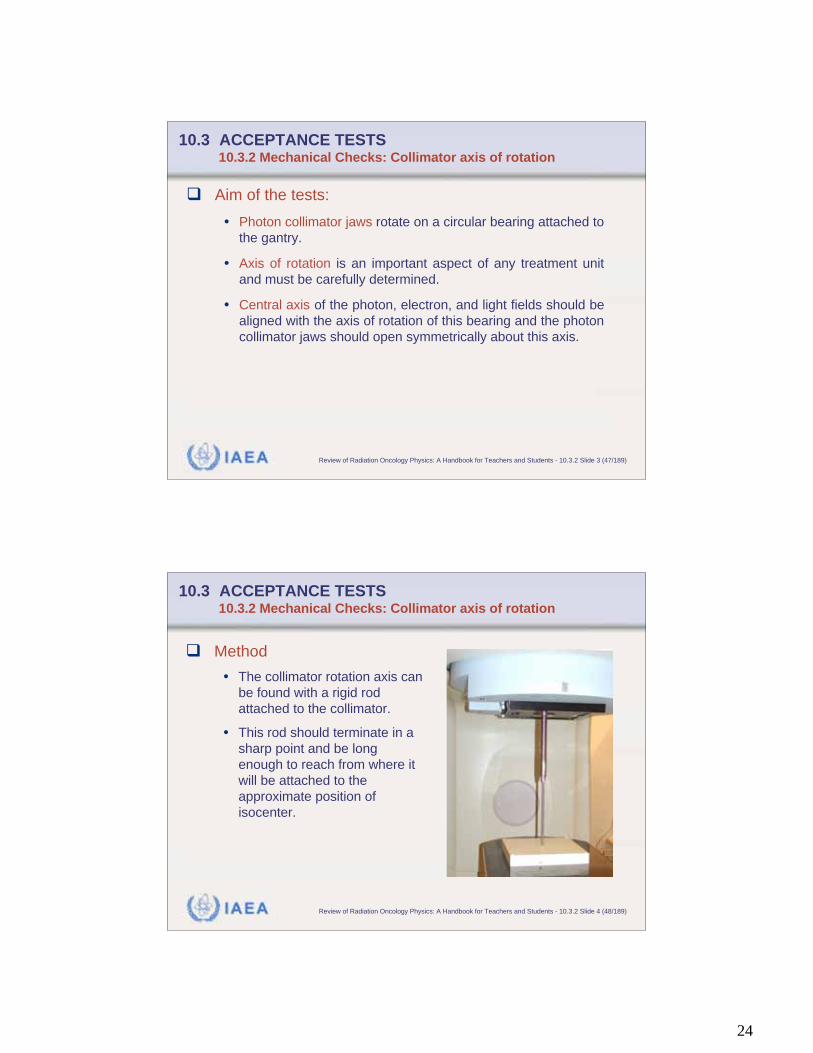
10.3 ACCEPTANCE TESTS 10.3.2 Mechanical Checks: Collimator axis of rotation
Aim of the tests:
• Photon collimator jaws rotate on a circular bearing attached to
the gantry.
• Axis of rotation is an important aspect of any treatment unit
and must be carefully determined.
• Central axis of the photon, electron, and light fields should be
aligned with the axis of rotation of this bearing and the photon
collimator jaws should open symmetrically about this axis.
IAEA Review of Radiation Oncology Physics: A Handbook for Teachers and Students - 10.3.2 Slide 4 (48/189)
10.3 ACCEPTANCE TESTS 10.3.2 Mechanical Checks: Collimator axis of rotation
Method
• The collimator rotation axis can
be found with a rigid rod
attached to the collimator.
• This rod should terminate in a
sharp point and be long
enough to reach from where it
will be attached to the
approximate position of
isocenter.

25
IAEA Review of Radiation Oncology Physics: A Handbook for Teachers and Students - 10.3.2 Slide 5 (49/189)
10.3 ACCEPTANCE TESTS 10.3.2 Mechanical Checks: Collimator axis of rotation
Practical suggestions
• The gantry should be positioned to point the collimator axisvertically downward and then the rod is attached to thecollimator housing.
• Millimeter graph paper is attached to the patient treatmentcouch and the treatment couch is raised to contact the point ofthe rod.
• With the rod rigidly mounted, the collimator is rotated through itsrange of motion. The point of the rod will trace out an arc as thecollimator is rotated.
• The point of the rod is adjusted to be near the center of this arc.
• This point should be the collimator axis of rotation. This processis continued until the minimum radius of the arc is obtained.
IAEA Review of Radiation Oncology Physics: A Handbook for Teachers and Students - 10.3.2 Slide 6 (50/189)
10.3 ACCEPTANCE TESTS 10.3.2 Mechanical Checks: Collimator axis of rotation
Expected result
• The minimum radius is the precision of the collimator axis of
rotation.
• In most cases this arc will reduce to a point but should not
exceed 1 mm in radius in any event.
26
IAEA Review of Radiation Oncology Physics: A Handbook for Teachers and Students - 10.3.2 Slide 7 (51/189)
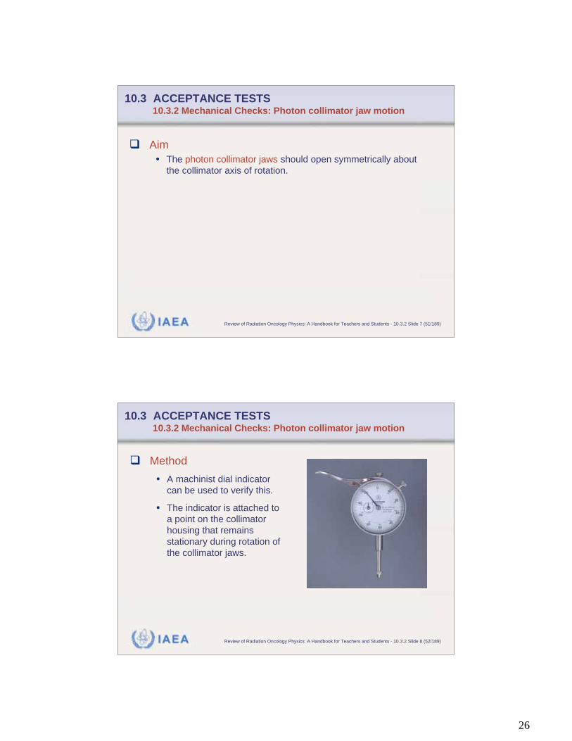
10.3 ACCEPTANCE TESTS 10.3.2 Mechanical Checks: Photon collimator jaw motion
Aim
• The photon collimator jaws should open symmetrically about
the collimator axis of rotation.
IAEA Review of Radiation Oncology Physics: A Handbook for Teachers and Students - 10.3.2 Slide 8 (52/189)
10.3 ACCEPTANCE TESTS 10.3.2 Mechanical Checks: Photon collimator jaw motion
Method
• A machinist dial indicator
can be used to verify this.
• The indicator is attached to
a point on the collimator
housing that remains
stationary during rotation of
the collimator jaws.
27
IAEA Review of Radiation Oncology Physics: A Handbook for Teachers and Students - 10.3.2 Slide 9 (53/189)
10.3 ACCEPTANCE TESTS 10.3.2 Mechanical Checks: Photon collimator jaw motion
Practical suggestions
• The feeler of the indicator is brought into contact with one set of
jaws and the reading is recorded.
• Collimator is then rotated through 180º and again the indicator is
brought into contact with the jaws and the reading is recorded.
• Collimator jaw symmetry about the rotation axis is one half of the
difference in the two readings. This value projected to the
isocenter should be less than 1 mm. This procedure is repeated
for the other set of collimator jaws.
IAEA Review of Radiation Oncology Physics: A Handbook for Teachers and Students - 10.3.2 Slide 10 (54/189)
10.3 ACCEPTANCE TESTS 10.3.2 Mechanical Checks: Photon collimator jaw motion
Expected result
• This value projected to the isocenter should be less than 1 mm.
• This procedure is repeated for the other set of collimator jaws.
28
IAEA Review of Radiation Oncology Physics: A Handbook for Teachers and Students - 10.3.2 Slide 11 (55/189)
10.3 ACCEPTANCE TESTS 10.3.2 Mechanical Checks: Photon collimator jaw motion
Aim
• The two sets of collimator jaws should be perpendicular to each
other.
IAEA Review of Radiation Oncology Physics: A Handbook for Teachers and Students - 10.3.2 Slide 12 (56/189)
10.3 ACCEPTANCE TESTS 10.3.2 Mechanical Checks: Photon collimator jaw motion
Method
• To check this, the gantry is rotated to orient the collimator
axis of rotation horizontally.
• Then the collimator is rotated to place one set of jaws
horizontally.
• A spirit level is placed on the jaws to verify they are
horizontal.
• Then the spirit level is used to verify that the vertically
positioned jaws are vertical.
29
IAEA Review of Radiation Oncology Physics: A Handbook for Teachers and Students - 10.3.2 Slide 13 (57/189)
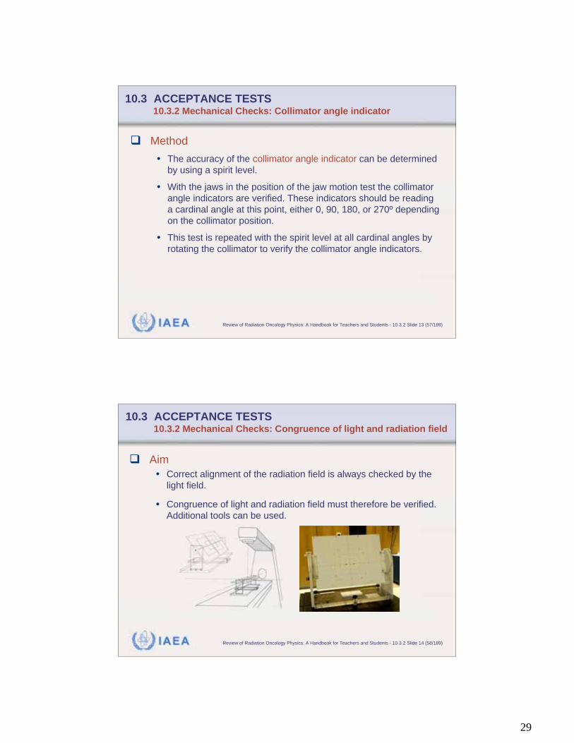
10.3 ACCEPTANCE TESTS 10.3.2 Mechanical Checks: Collimator angle indicator
Method
• The accuracy of the collimator angle indicator can be determined
by using a spirit level.
• With the jaws in the position of the jaw motion test the collimator
angle indicators are verified. These indicators should be reading
a cardinal angle at this point, either 0, 90, 180, or 270º depending
on the collimator position.
• This test is repeated with the spirit level at all cardinal angles by
rotating the collimator to verify the collimator angle indicators.
IAEA Review of Radiation Oncology Physics: A Handbook for Teachers and Students - 10.3.2 Slide 14 (58/189)
10.3 ACCEPTANCE TESTS 10.3.2 Mechanical Checks: Congruence of light and radiation field
Aim
• Correct alignment of the radiation field is always checked by the
light field.
• Congruence of light and radiation field must therefore be verified.
Additional tools can be used.

30
IAEA Review of Radiation Oncology Physics: A Handbook for Teachers and Students - 10.3.2 Slide 15 (59/189)
10.3 ACCEPTANCE TESTS 10.3.2 Mechanical Checks: Congruence of light and radiation field
Method: Adjustment
• With millimeter graph paper attached to the patient treat-
ment couch, the couch is raised to nominal isocenter
distance.
• The gantry is oriented to point the collimator axis of rotation
vertically downward. The position of the collimator axis of
rotation is indicated on this graph paper.
• The projected image of the cross-hair should be coincident
with the collimator axis of rotation and should not deviate
more than 1 mm from this point as the collimator is rotated
through its full range of motion.
IAEA Review of Radiation Oncology Physics: A Handbook for Teachers and Students - 10.3.2 Slide 16 (60/189)
10.3 ACCEPTANCE TESTS 10.3.2 Mechanical Checks: Congruence of light and radiation field
Method (continued)
• The congruence of the light and radiation field can now beverified. A radiographic film is placed perpendicularly to thecollimator axis of rotation.
• The edges of the light field are marked with radio-opaque objectsor by pricking holes with a pin through the ready pack film in thecorners of the light field.
• Plastic slabs are placed on top of the film such, that the film ispositioned near zmax
• The film is irradiated to yield an optical density between 1 and 2.
31
IAEA Review of Radiation Oncology Physics: A Handbook for Teachers and Students - 10.3.2 Slide 17 (61/189)
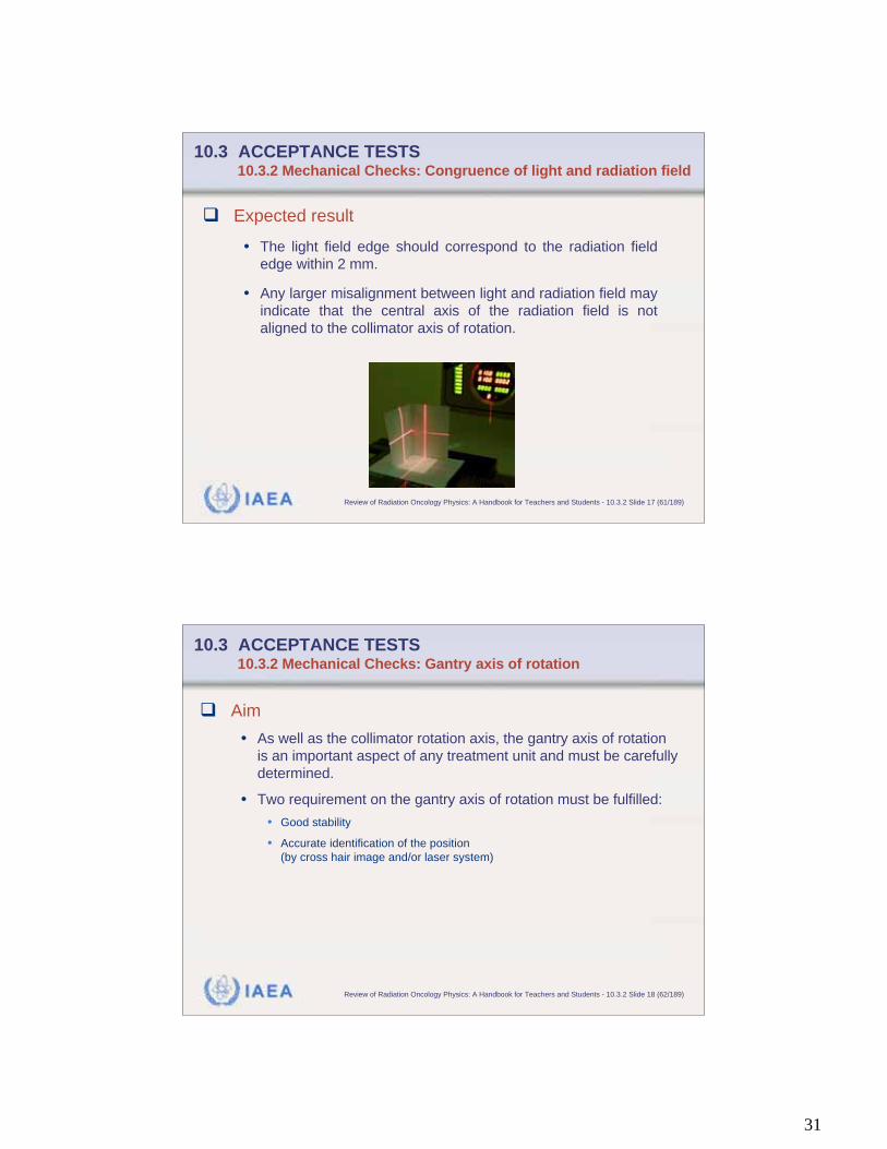
10.3 ACCEPTANCE TESTS 10.3.2 Mechanical Checks: Congruence of light and radiation field
Expected result
• The light field edge should correspond to the radiation field
edge within 2 mm.
• Any larger misalignment between light and radiation field may
indicate that the central axis of the radiation field is not
aligned to the collimator axis of rotation.
IAEA Review of Radiation Oncology Physics: A Handbook for Teachers and Students - 10.3.2 Slide 18 (62/189)
10.3 ACCEPTANCE TESTS 10.3.2 Mechanical Checks: Gantry axis of rotation
Aim
• As well as the collimator rotation axis, the gantry axis of rotation
is an important aspect of any treatment unit and must be carefully
determined.
• Two requirement on the gantry axis of rotation must be fulfilled:
• Good stability
• Accurate identification of the position
(by cross hair image and/or laser system)
32
IAEA Review of Radiation Oncology Physics: A Handbook for Teachers and Students - 10.3.2 Slide 19 (63/189)
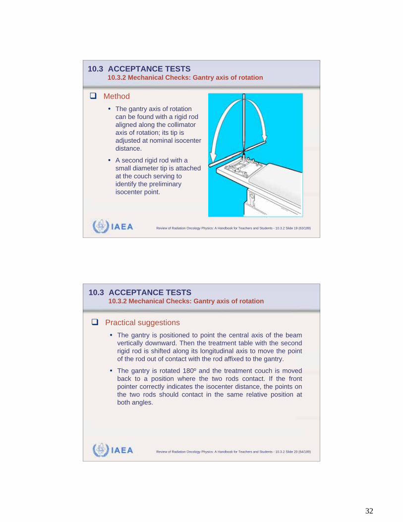
10.3 ACCEPTANCE TESTS 10.3.2 Mechanical Checks: Gantry axis of rotation
Method
• The gantry axis of rotation
can be found with a rigid rod
aligned along the collimator
axis of rotation; its tip is
adjusted at nominal isocenter
distance.
• A second rigid rod with a
small diameter tip is attached
at the couch serving to
identify the preliminary
isocenter point.
IAEA Review of Radiation Oncology Physics: A Handbook for Teachers and Students - 10.3.2 Slide 20 (64/189)
10.3 ACCEPTANCE TESTS 10.3.2 Mechanical Checks: Gantry axis of rotation
Practical suggestions
• The gantry is positioned to point the central axis of the beam
vertically downward. Then the treatment table with the second
rigid rod is shifted along its longitudinal axis to move the point
of the rod out of contact with the rod affixed to the gantry.
• The gantry is rotated 180º and the treatment couch is moved
back to a position where the two rods contact. If the front
pointer correctly indicates the isocenter distance, the points on
the two rods should contact in the same relative position at
both angles.
33
IAEA Review of Radiation Oncology Physics: A Handbook for Teachers and Students - 10.3.2 Slide 21 (65/189)
10.3 ACCEPTANCE TESTS 10.3.2 Mechanical Checks: Gantry axis of rotation
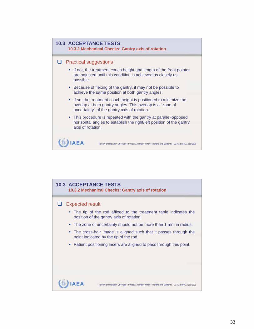
Practical suggestions
• If not, the treatment couch height and length of the front pointer
are adjusted until this condition is achieved as closely as
possible.
• Because of flexing of the gantry, it may not be possible to
achieve the same position at both gantry angles.
• If so, the treatment couch height is positioned to minimize the
overlap at both gantry angles. This overlap is a “zone of
uncertainty” of the gantry axis of rotation.
• This procedure is repeated with the gantry at parallel-opposed
horizontal angles to establish the right/left position of the gantry
axis of rotation.
IAEA Review of Radiation Oncology Physics: A Handbook for Teachers and Students - 10.3.2 Slide 22 (66/189)
10.3 ACCEPTANCE TESTS 10.3.2 Mechanical Checks: Gantry axis of rotation
Expected result
• The tip of the rod affixed to the treatment table indicates the
position of the gantry axis of rotation.
• The zone of uncertainty should not be more than 1 mm in radius.
• The cross-hair image is aligned such that it passes through the
point indicated by the tip of the rod.
• Patient positioning lasers are aligned to pass through this point.
34
IAEA Review of Radiation Oncology Physics: A Handbook for Teachers and Students - 10.3.2 Slide 23 (67/189)
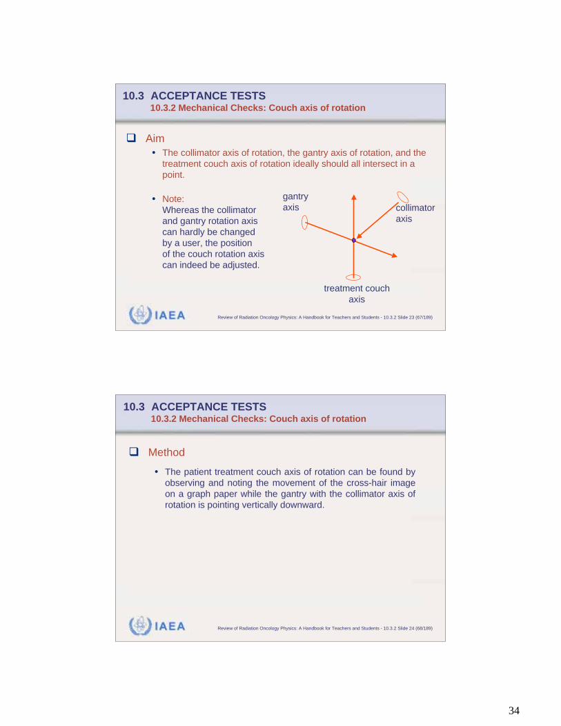
10.3 ACCEPTANCE TESTS 10.3.2 Mechanical Checks: Couch axis of rotation
Aim
• The collimator axis of rotation, the gantry axis of rotation, and the
treatment couch axis of rotation ideally should all intersect in a
point.
• Note:
Whereas the collimator
and gantry rotation axis
can hardly be changed
by a user, the position
of the couch rotation axis
can indeed be adjusted.
collimator
axis
treatment couch
axis
gantry
axis
IAEA Review of Radiation Oncology Physics: A Handbook for Teachers and Students - 10.3.2 Slide 24 (68/189)
10.3 ACCEPTANCE TESTS 10.3.2 Mechanical Checks: Couch axis of rotation
Method
• The patient treatment couch axis of rotation can be found by
observing and noting the movement of the cross-hair image
on a graph paper while the gantry with the collimator axis of
rotation is pointing vertically downward.
35
IAEA Review of Radiation Oncology Physics: A Handbook for Teachers and Students - 10.3.2 Slide 25 (69/189)
10.3 ACCEPTANCE TESTS 10.3.2 Mechanical Checks: Couch axis of rotation
Expected result
• The cross-hair image should trace an arc with a radius of less
than 1 mm.
IAEA Review of Radiation Oncology Physics: A Handbook for Teachers and Students - 10.3.2 Slide 26 (70/189)
10.3 ACCEPTANCE TESTS 10.3.2 Mechanical Checks: Radiation isocenter
Aim
• The radiation isocenter is primarily determined by the intersection
of the three rotation axes: the collimator axis of rotation, the
gantry axis of rotation, and the treatment couch axis of rotation.
• In practice, they are not all intersecting at a point, but within a
sphere.
• The radius of this sphere determines the isocenter uncertainty.
• Radiation isocenter should be determined for all photon energies.
36
IAEA Review of Radiation Oncology Physics: A Handbook for Teachers and Students - 10.3.2 Slide 27 (71/189)
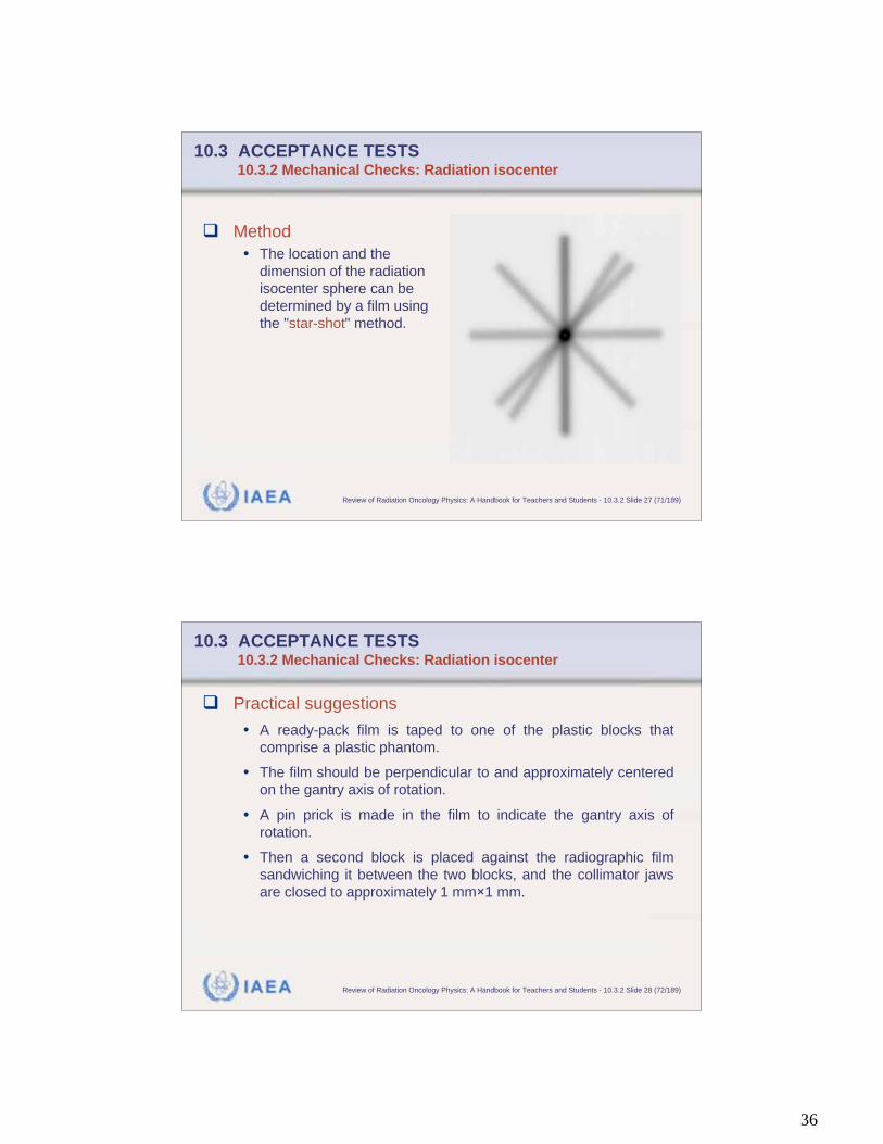
10.3 ACCEPTANCE TESTS 10.3.2 Mechanical Checks: Radiation isocenter
Method
• The location and the
dimension of the radiation
isocenter sphere can be
determined by a film using
the "star-shot" method.
IAEA Review of Radiation Oncology Physics: A Handbook for Teachers and Students - 10.3.2 Slide 28 (72/189)
10.3 ACCEPTANCE TESTS 10.3.2 Mechanical Checks: Radiation isocenter
Practical suggestions
• A ready-pack film is taped to one of the plastic blocks that
comprise a plastic phantom.
• The film should be perpendicular to and approximately centered
on the gantry axis of rotation.
• A pin prick is made in the film to indicate the gantry axis of
rotation.
• Then a second block is placed against the radiographic film
sandwiching it between the two blocks, and the collimator jaws
are closed to approximately 1 mm 1 mm.
37
IAEA Review of Radiation Oncology Physics: A Handbook for Teachers and Students - 10.3.2 Slide 29 (73/189)
10.3 ACCEPTANCE TESTS 10.3.2 Mechanical Checks: Radiation isocenter
Practical suggestions
• Without touching the film, the film is exposed at a number of
different gantry angles in all four quadrants.
• In addition, the film can be exposed at a number of different
couch angles.
• The processed film should show a multi-armed cross, referred to
as a “star shot.”
• The point where all central axes intersect is the radiation
isocenter.
IAEA Review of Radiation Oncology Physics: A Handbook for Teachers and Students - 10.3.2 Slide 30 (74/189)
10.3 ACCEPTANCE TESTS 10.3.2 Mechanical Checks: Radiation isocenter
Expected result
• Because of gantry flex, it may be a few millimeters wide but
should not exceed 4 mm. This point should be within 1 mm to 2
mm of the mechanical isocenter indicated by the pin-prick on the
film.
• Collimator axis of rotation, the gantry axis of rotation and the
treatment table axis of rotation should all intersect in a sphere.
The radius of this sphere determines the isocentre uncertainty.
• The isocentre radius should be no greater than 1 mm, and for
machines used in radiosurgery should not exceed 0.5 mm.

38
IAEA Review of Radiation Oncology Physics: A Handbook for Teachers and Students - 10.3.2 Slide 31 (75/189)
10.3 ACCEPTANCE TESTS 10.3.2 Mechanical Checks: Optical distance indicator
Method
• A convenient method to
verify the accuracy of the
optical distance indicator
over the range of its read-
out consists of projecting
the indicator on top of a
plastic phantom with
different heights.
IAEA Review of Radiation Oncology Physics: A Handbook for Teachers and Students - 10.3.2 Slide 32 (76/189)
10.3 ACCEPTANCE TESTS 10.3.2 Mechanical Checks: Optical distance indicator
Practical suggestions
• With the gantry positioned with the collimator axis of rotation
pointing vertically downward five of the 5 cm thick blocks are
placed on the treatment couch with the top of the top block at
isocenter.
• Optical distance indicator should read isocentre distance.
• By adding and removing 5 cm blocks the optical distance
indicator can be easily verified at other distances in 5 cm
increments.
39
IAEA Review of Radiation Oncology Physics: A Handbook for Teachers and Students - 10.3.2 Slide 33 (77/189)
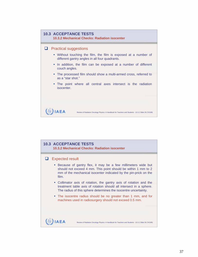
10.3 ACCEPTANCE TESTS 10.3.2 Mechanical Checks: Optical distance indicator
Expected results
• Deviation of the actual height from that indicated by the optical
distance indicator must comply with the stated specification.
IAEA Review of Radiation Oncology Physics: A Handbook for Teachers and Students - 10.3.2 Slide 34 (78/189)
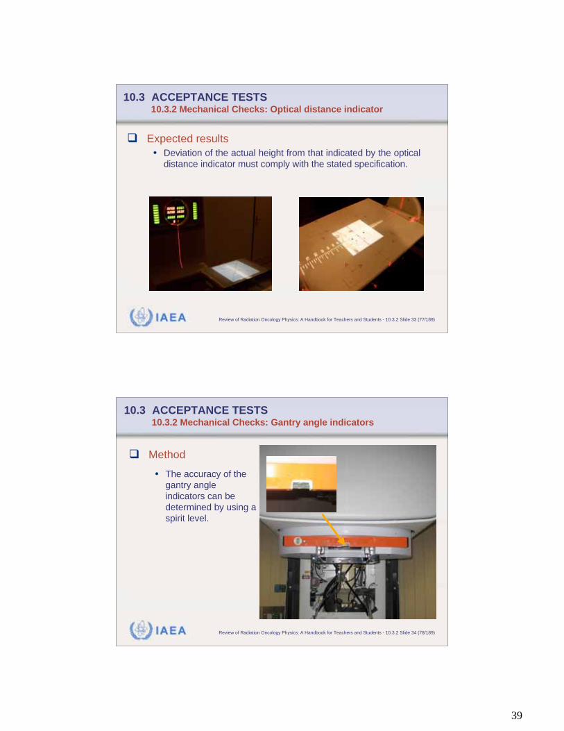
10.3 ACCEPTANCE TESTS 10.3.2 Mechanical Checks: Gantry angle indicators
Method
• The accuracy of the
gantry angle
indicators can be
determined by using a
spirit level.

40
IAEA Review of Radiation Oncology Physics: A Handbook for Teachers and Students - 10.3.2 Slide 35 (79/189)
10.3 ACCEPTANCE TESTS 10.3.2 Mechanical Checks: Gantry angle indicators
Practical suggestions
• At each of the nominal cardinal angles the spirit level should
indicate correct level.
• Some spirit levels also have an indicator for 45° angles that
can be used to check angles of 45°, 135°, 225°, and 315°.
IAEA Review of Radiation Oncology Physics: A Handbook for Teachers and Students - 10.3.2 Slide 36 (80/189)
10.3 ACCEPTANCE TESTS 10.3.2 Mechanical Checks: Gantry angle indicators
Expected results
• The gantry angle indicators should be accurate to
within 0.5°.
41
IAEA Review of Radiation Oncology Physics: A Handbook for Teachers and Students - 10.3.2 Slide 37 (81/189)
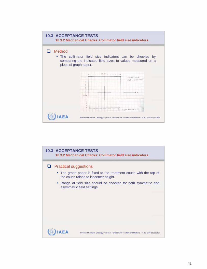
10.3 ACCEPTANCE TESTS 10.3.2 Mechanical Checks: Collimator field size indicators
Method
• The collimator field size indicators can be checked by
comparing the indicated field sizes to values measured on a
piece of graph paper.
IAEA Review of Radiation Oncology Physics: A Handbook for Teachers and Students - 10.3.2 Slide 38 (82/189)
10.3 ACCEPTANCE TESTS 10.3.2 Mechanical Checks: Collimator field size indicators
Practical suggestions
• The graph paper is fixed to the treatment couch with the top of
the couch raised to isocenter height.
• Range of field size should be checked for both symmetric and
asymmetric field settings.
42
IAEA Review of Radiation Oncology Physics: A Handbook for Teachers and Students - 10.3.2 Slide 39 (83/189)
10.3 ACCEPTANCE TESTS 10.3.2 Mechanical Checks: Collimator field size indicators
Expected results
• The field size indicators should be accurate to within 2 mm.
• (Suggested in:
Comprehensive QA for Radiation Oncology, AAPM Task Group 40)
IAEA Review of Radiation Oncology Physics: A Handbook for Teachers and Students - 10.3.2 Slide 40 (84/189)
10.3 ACCEPTANCE TESTS 10.3.2 Mechanical Checks: Couch motions
Aim
• The patient treatment couch should exactly move in vertical and
horizontal planes.
43
IAEA Review of Radiation Oncology Physics: A Handbook for Teachers and Students - 10.3.2 Slide 41 (85/189)
10.3 ACCEPTANCE TESTS 10.3.2 Mechanical Checks: Couch motions
Method
• The vertical motion can be checked by attaching a piece of
millimeter graph paper to the treatment couch and with the
gantry positioned with the collimator axis of rotation pointing
vertically downward.
IAEA Review of Radiation Oncology Physics: A Handbook for Teachers and Students - 10.3.2 Slide 42 (86/189)
10.3 ACCEPTANCE TESTS 10.3.2 Mechanical Checks: Couch motions
Practical suggestions
• Mark the position of the image of the cross-hair on the paper.
• As the treatment couch is moved through its vertical range, the
cross-hair image should not deviate from this mark.
• The horizontal motions can be checked in a similar fashion with
the gantry positioned with the collimator axis in a horizontal
plane.
• By rotating the treatment couch 90 degrees from its “neutral”
position, the longitudinal motion can be verified.

44
IAEA Review of Radiation Oncology Physics: A Handbook for Teachers and Students - 10.3.2 Slide 43 (87/189)
10.3 ACCEPTANCE TESTS 10.3.2 Mechanical Checks: Couch motions
Expected results
• Deviation of the movement from vertical and horizontal planes
must comply with the specification.
IAEA Review of Radiation Oncology Physics: A Handbook for Teachers and Students - 10.3.3 Slide 1 (88/189)
10.3 ACCEPTANCE TESTS 10.3.3 Dosimetry Measurements
After completion of the mechanical checks, dosimetry
measurements must be performed.
Dosimetry measurements establish that:
• Central axis percentage depth doses
• Off axis characteristics of clinical beams
meet the specifications.
The characteristics of the monitor ionization chamber of
a linear accelerator or a timer of a cobalt-60 unit are
also determined.
45
IAEA Review of Radiation Oncology Physics: A Handbook for Teachers and Students - 10.3.3 Slide 2 (89/189)
10.3 ACCEPTANCE TESTS 10.3.3 Dosimetry Measurements
The dosimetry measurements include:
• Photon energy
• Photon beam uniformity
• Photon penumbra
• Electron energy
• Electron beam bremsstrahlung contamination
• Electron beam uniformity
• Electron penumbra
• Monitor characteristics
• Arc therapy
IAEA Review of Radiation Oncology Physics: A Handbook for Teachers and Students - 10.3.3 Slide 3 (90/189)
10.3 ACCEPTANCE TESTS 10.3.3 Dosimetry Measurements
The following dosimetry measurement descriptions are
structured such that for each test two characteristics
are given:
• Parameter used to specify the dosimetrical property.
• Method used;
46
IAEA Review of Radiation Oncology Physics: A Handbook for Teachers and Students - 10.3.3 Slide 4 (91/189)
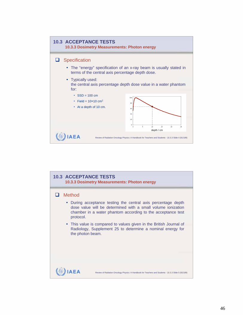
10.3 ACCEPTANCE TESTS 10.3.3 Dosimetry Measurements: Photon energy
Specification
• The “energy” specification of an x-ray beam is usually stated in
terms of the central axis percentage depth dose.
• Typically used:
the central axis percentage depth dose value in a water phantom
for:
• SSD = 100 cm
• Field = 10 10 cm2
• At a depth of 10 cm.
depth / cm
0 5 10 15 20 25
0
20
40
60
80
100
IAEA Review of Radiation Oncology Physics: A Handbook for Teachers and Students - 10.3.3 Slide 5 (92/189)
10.3 ACCEPTANCE TESTS 10.3.3 Dosimetry Measurements: Photon energy
Method
• During acceptance testing the central axis percentage depth
dose value will be determined with a small volume ionization
chamber in a water phantom according to the acceptance test
protocol.
• This value is compared to values given in the British Journal of
Radiology, Supplement 25 to determine a nominal energy for
the photon beam.
47
IAEA Review of Radiation Oncology Physics: A Handbook for Teachers and Students - 10.3.3 Slide 6 (93/189)
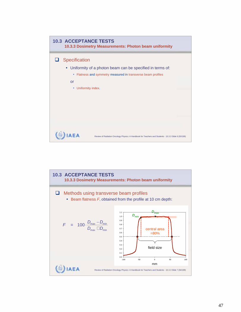
10.3 ACCEPTANCE TESTS 10.3.3 Dosimetry Measurements: Photon beam uniformity
Specification
• Uniformity of a photon beam can be specified in terms of:
• Flatness and symmetry measured in transverse beam profiles
or
• Uniformity index.
IAEA Review of Radiation Oncology Physics: A Handbook for Teachers and Students - 10.3.3 Slide 7 (94/189)
10.3 ACCEPTANCE TESTS 10.3.3 Dosimetry Measurements: Photon beam uniformity
Methods using transverse beam profiles
• Beam flatness F, obtained from the profile at 10 cm depth:
Col 1 vs Col 2 Col 1 vs Col 2
mm
-100 -50 0 50 100
0.0
0.1
0.2
0.3
0.4
0.5
0.6
0.7
0.8
0.9
1.0
1.1
field size
central area
=80%
DmaxDmin
=+
max min
max min
100D D
FD D
48
IAEA Review of Radiation Oncology Physics: A Handbook for Teachers and Students - 10.3.3 Slide 8 (95/189)
10.3 ACCEPTANCE TESTS 10.3.3 Dosimetry Measurements: Photon beam uniformity
Methods using transverse beam profiles
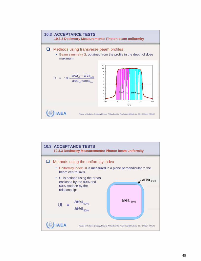
• Beam symmetry S, obtained from the profile in the depth of dose
maximum:
S = 100area
leftarea
right
arealeft
+arearight
mm
-100 -50 0 50 100
0
10
20
30
40
50
60
70
80
90
100
110
area left area right
IAEA Review of Radiation Oncology Physics: A Handbook for Teachers and Students - 10.3.3 Slide 9 (96/189)
10.3 ACCEPTANCE TESTS 10.3.3 Dosimetry Measurements: Photon beam uniformity
Methods using the uniformity index
• Uniformity index UI is measured in a plane perpendicular to the
beam central axis.
• UI is defined using the areas
enclosed by the 90% and
50% isodose by the
relationship:
UI =area
90%
area50%
area 50%
area 90%
49
IAEA Review of Radiation Oncology Physics: A Handbook for Teachers and Students - 10.3.3 Slide 10 (97/189)
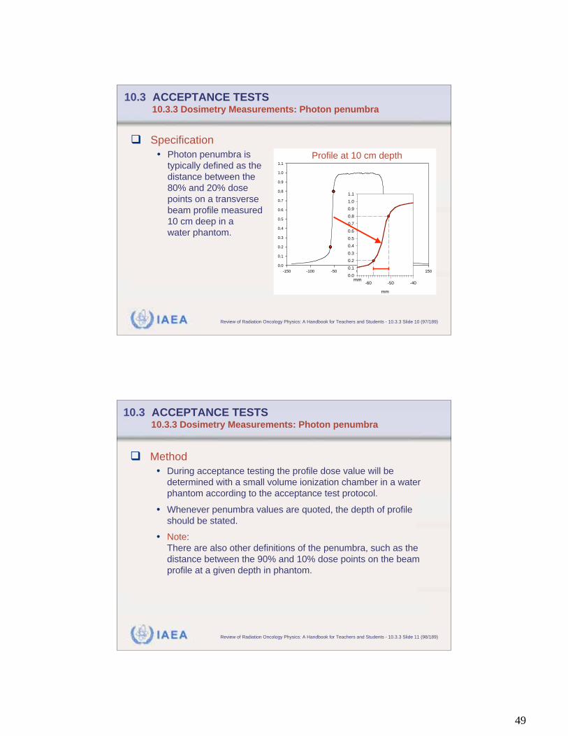
10.3 ACCEPTANCE TESTS 10.3.3 Dosimetry Measurements: Photon penumbra
Specification
• Photon penumbra is
typically defined as the
distance between the
80% and 20% dose
points on a transverse
beam profile measured
10 cm deep in a
water phantom.
mm
-150 -100 -50 0 50 100 150
0.0
0.1
0.2
0.3
0.4
0.5
0.6
0.7
0.8
0.9
1.0
1.1
mm
-60 -50 -40
0.0
0.1
0.2
0.3
0.4
0.5
0.6
0.7
0.8
0.9
1.0
1.1
Profile at 10 cm depth
IAEA Review of Radiation Oncology Physics: A Handbook for Teachers and Students - 10.3.3 Slide 11 (98/189)
10.3 ACCEPTANCE TESTS 10.3.3 Dosimetry Measurements: Photon penumbra
Method
• During acceptance testing the profile dose value will be
determined with a small volume ionization chamber in a water
phantom according to the acceptance test protocol.
• Whenever penumbra values are quoted, the depth of profile
should be stated.
• Note:
There are also other definitions of the penumbra, such as the
distance between the 90% and 10% dose points on the beam
profile at a given depth in phantom.
50
IAEA Review of Radiation Oncology Physics: A Handbook for Teachers and Students - 10.3.3 Slide 12 (99/189)
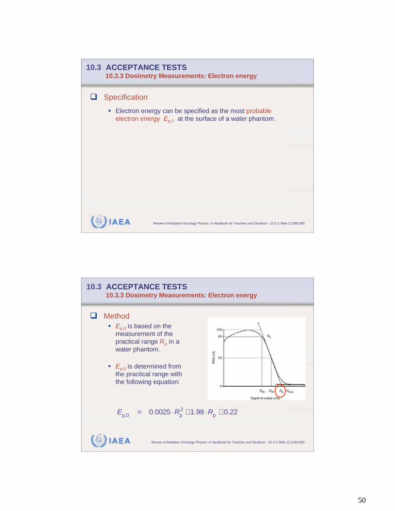
10.3 ACCEPTANCE TESTS 10.3.3 Dosimetry Measurements: Electron energy
Specification
• Electron energy can be specified as the most probable
electron energy Ep,0 at the surface of a water phantom.
IAEA Review of Radiation Oncology Physics: A Handbook for Teachers and Students - 10.3.3 Slide 13 (100/189)
10.3 ACCEPTANCE TESTS 10.3.3 Dosimetry Measurements: Electron energy
Method
• Ep,0 is based on the
measurement of the
practical range Rp in a
water phantom.
• Ep,0 is determined from
the practical range with
the following equation:
E
p,0= 0.0025 R
p2
+1.98 Rp
+ 0.22
51
IAEA Review of Radiation Oncology Physics: A Handbook for Teachers and Students - 10.3.3 Slide 14 (101/189)
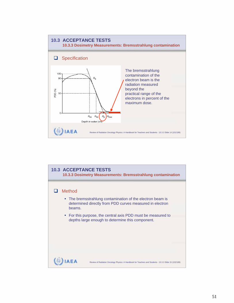
10.3 ACCEPTANCE TESTS 10.3.3 Dosimetry Measurements: Bremsstrahlung contamination
Specification
The bremsstrahlung
contamination of the
electron beam is the
radiation measured
beyond the
practical range of the
electrons in percent of the
maximum dose.
IAEA Review of Radiation Oncology Physics: A Handbook for Teachers and Students - 10.3.3 Slide 15 (102/189)
10.3 ACCEPTANCE TESTS 10.3.3 Dosimetry Measurements: Bremsstrahlung contamination
Method
• The bremsstrahlung contamination of the electron beam is
determined directly from PDD curves measured in electron
beams.
• For this purpose, the central axis PDD must be measured to
depths large enough to determine this component.
52
IAEA Review of Radiation Oncology Physics: A Handbook for Teachers and Students - 10.3.3 Slide 16 (103/189)
10.3 ACCEPTANCE TESTS 10.3.3 Dosimetry Measurements: Electron beam uniformity
Specification
• Uniformity of an electron beam can be specified similar to that of
photon beams in terms of:
• Flatness and symmetry measured in
transverse beam profiles
or
• Uniformity index
IAEA Review of Radiation Oncology Physics: A Handbook for Teachers and Students - 10.3.3 Slide 17 (104/189)
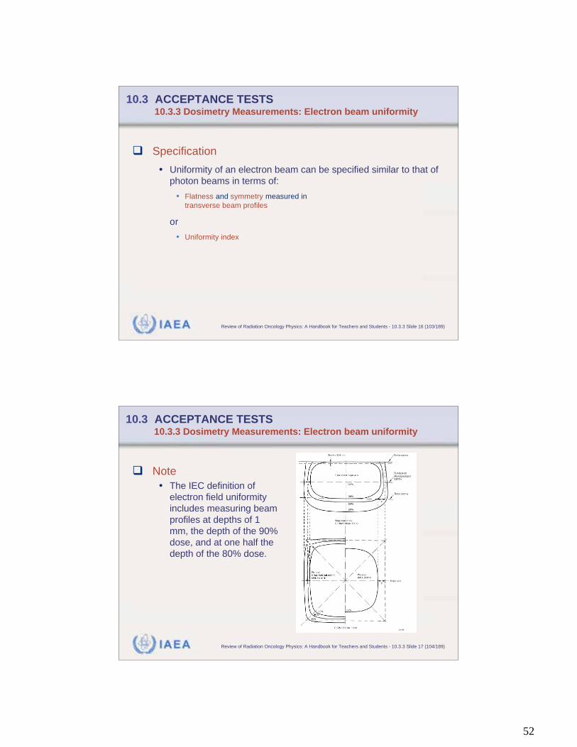
10.3 ACCEPTANCE TESTS 10.3.3 Dosimetry Measurements: Electron beam uniformity
Note
• The IEC definition of
electron field uniformity
includes measuring beam
profiles at depths of 1
mm, the depth of the 90%
dose, and at one half the
depth of the 80% dose.
53
IAEA Review of Radiation Oncology Physics: A Handbook for Teachers and Students - 10.3.3 Slide 18 (105/189)
10.3 ACCEPTANCE TESTS 10.3.3 Dosimetry Measurements: Monitor characteristics
Specifications
• The monitor unit device consists of:
• Timer in case of a cobalt unit
• Ionization chamber that intercepts the entire treatment beam in case of a
linear accelerator.
• The following characteristics of the monitor unit device must be
checked:
• Linearity
• Independence from temperature-pressure fluctuations
• Independence from dose rate and gantry angle.
IAEA Review of Radiation Oncology Physics: A Handbook for Teachers and Students - 10.3.3 Slide 19 (106/189)
10.3 ACCEPTANCE TESTS 10.3.3 Dosimetry Measurements: Monitor characteristics
Methods: Linearity
• Linearity of the monitor unit device should be verified by
placing an ionization chamber at a fixed depth in a phantom
and recording the ionization collected during irradiations with
different time or monitor unit settings over the range of the
monitor.
• The collected ionization can be plotted on the y-axis and the
monitor or time setting on the x-axis. These data should
produce a straight line indicating a linear response of the
monitor unit device or timer.
54
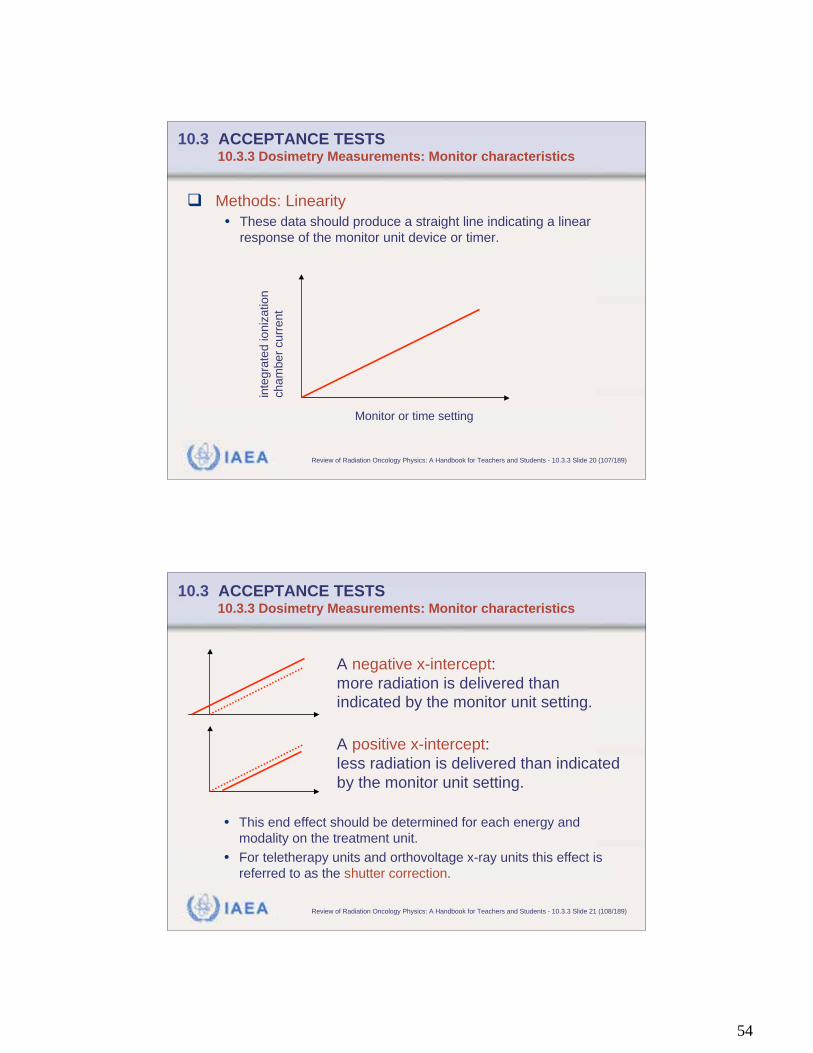
IAEA Review of Radiation Oncology Physics: A Handbook for Teachers and Students - 10.3.3 Slide 20 (107/189)
10.3 ACCEPTANCE TESTS 10.3.3 Dosimetry Measurements: Monitor characteristics
Methods: Linearity
• These data should produce a straight line indicating a linear
response of the monitor unit device or timer.
inte
gra
ted ioniz
ation
cham
ber
curr
ent
Monitor or time setting
IAEA Review of Radiation Oncology Physics: A Handbook for Teachers and Students - 10.3.3 Slide 21 (108/189)
10.3 ACCEPTANCE TESTS 10.3.3 Dosimetry Measurements: Monitor characteristics
A negative x-intercept:
more radiation is delivered than
indicated by the monitor unit setting.
A positive x-intercept:
less radiation is delivered than indicated
by the monitor unit setting.
• This end effect should be determined for each energy and
modality on the treatment unit.
• For teletherapy units and orthovoltage x-ray units this effect is
referred to as the shutter correction.

55
IAEA Review of Radiation Oncology Physics: A Handbook for Teachers and Students - 10.3.3 Slide 22 (109/189)
10.3 ACCEPTANCE TESTS 10.3.3 Dosimetry Measurements: Monitor characteristics
Methods: Independence from temperature-pressure
fluctuations
• Most linear accelerator manufacturers design the monitor
chamber to be:
• Either sealed so that the monitor chamber calibration is indepen-dent of
temperature-pressure fluctuations
• Or the monitor chamber has a temperature-pressure compensation circuit.
• Effectiveness of either method should be evaluated by
determining the long-term stability of the monitor chamber
calibration. This evaluation can be performed during
commissioning by measuring the output each morning in a
plastic phantom in a set up designed to reduce set up
variations and increase precision of the measurement.
IAEA Review of Radiation Oncology Physics: A Handbook for Teachers and Students - 10.3.3 Slide 23 (110/189)
10.3 ACCEPTANCE TESTS 10.3.3 Dosimetry Measurements: Monitor characteristics
Methods: Independence from dose rate and gantry
angle
• Linacs usually provide the capability for irradiating at several
different dose rates.
• Different dose rates may change the collection efficiency of
the monitor ionization chamber, which would change the
calibration (cGy/MU) of the monitor ionization chamber.
• The calibration of the monitor ionization chamber should be
determined at all available dose rates of the treatment unit.
• The constancy of output with gantry angle should also be
verified.
56
IAEA Review of Radiation Oncology Physics: A Handbook for Teachers and Students - 10.3.3 Slide 24 (111/189)
10.3 ACCEPTANCE TESTS 10.3.3 Dosimetry Measurements: Arc therapy
Specification
• The rotation of arc or rotational therapy must exactly
terminate when the monitor or time setting and at the same
time the number of degrees for the desired arc is reached.
• Proper function is specified by a difference as small as
possible in monitor units (or time) as well as in degrees from
the setting.
IAEA Review of Radiation Oncology Physics: A Handbook for Teachers and Students - 10.3.3 Slide 25 (112/189)
10.3 ACCEPTANCE TESTS 10.3.3 Dosimetry Measurements: Arc therapy
Method
• A check is accomplished by setting a number of monitor units
on a linear accelerator or time on a cobalt-60 unit and a number
of degrees for the desired arc.
• Termination of radiation and treatment unit motion should agree
with the specification.
• This test should be carried out for all energies and modalities of
treatment and over the range of arc therapy geometry for which
arc therapy will be used.

57
IAEA Review of Radiation Oncology Physics: A Handbook for Teachers and Students - 10.4 Slide 1 (113/189)
10.4 COMMISSIONING
Characteristics
• Following equipment acceptance, characterization of the
equipment's performance over the whole range of possible
operation must be undertaken. This process is generally
referred to as commissioning.
• Another definition is that commissioning is the process of
preparing procedures, protocols, instructions, data, etc., for
clinical service.
• Clinical use can only begin when the physicist responsible for
commissioning is satisfied that all aspects have been
completed and that the equipment and any necessary data,
etc., are safe for use on patients.
IAEA Review of Radiation Oncology Physics: A Handbook for Teachers and Students - 10.4 Slide 2 (114/189)
Commissioning of an external beam radiotherapy device
includes a series of tasks:
• Acquiring all radiation beam data required for treatment.
• Organizing this data into a dosimetry data book.
• Entering this data into a computerized treatment planning
system.
• Developing all dosimetry, treatment planning, and treatment
procedures.
• Verifying the accuracy of these procedures.
• Establishing quality control tests and procedures.
• Training of all personnel.
10.4 COMMISSIONING
58
IAEA Review of Radiation Oncology Physics: A Handbook for Teachers and Students - 10.4 Slide 3 (115/189)
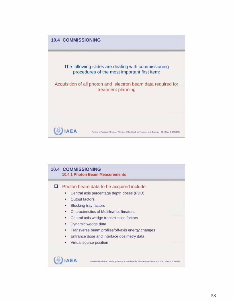
The following slides are dealing with commissioning
procedures of the most important first item:
Acquisition of all photon and electron beam data required for
treatment planning
10.4 COMMISSIONING
IAEA Review of Radiation Oncology Physics: A Handbook for Teachers and Students - 10.4.1 Slide 1 (116/189)
10.4 COMMISSIONING 10.4.1 Photon Beam Measurements
Photon beam data to be acquired include:
• Central axis percentage depth doses (PDD)
• Output factors
• Blocking tray factors
• Characteristics of Multileaf collimators
• Central axis wedge transmission factors
• Dynamic wedge data
• Transverse beam profiles/off-axis energy changes
• Entrance dose and interface dosimetry data
• Virtual source position
59
IAEA Review of Radiation Oncology Physics: A Handbook for Teachers and Students - 10.4.1 Slide 2 (117/189)
10.4 COMMISSIONING 10.4.1 Photon Beam Measurements: PDD
Method
• Central axis percentage depth doses are preferably measured
in a water phantom.
• For measurements plane-parallel ionization chambers with the
effective point of measurement placed at the nominal depth are
recommended.
• Note:
The effective point of measurement of a plane-parallel chamber
is on the inner surface of the entrance window, at the center of
the window for all beam qualities and depths.
IAEA Review of Radiation Oncology Physics: A Handbook for Teachers and Students - 10.4.1 Slide 3 (118/189)
10.4 COMMISSIONING 10.4.1 Photon Beam Measurements: PDD
Note:
• Ionization chambers always provide depth-ionization curves.
• Since stopping-power ratios and perturbation effects for
photon beams are almost independent of depth (except for the
buildup region of high energy x-rays), relative ionization
distributions can be used in a very good approximation as
relative distributions of absorbed dose.
60
IAEA Review of Radiation Oncology Physics: A Handbook for Teachers and Students - 10.4.1 Slide 4 (119/189)
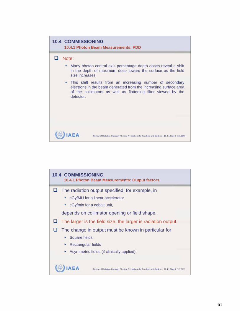
10.4 COMMISSIONING 10.4.1 Photon Beam Measurements: PDD
Method (continued)
• If a cylindrical ionization
chamber is used instead,
then the effective point
of measurement ( ) of
the chamber must be
taken into account.
• This may require that the complete depth-ionization
distribution be shifted toward the surface by a distance equal
to 0.6 rcyl where rcyl is the cavity radius of the cylindrical
ionization chamber.
real
depth0.6 rcyl
IAEA Review of Radiation Oncology Physics: A Handbook for Teachers and Students - 10.4.1 Slide 5 (120/189)
Practical suggestions
• PDD values should be measured in a water phantom over the
range of field sizes from 4 4 cm2 to 40 40 cm2.
• Increments between field sizes should be no greater than 5 cm
but are typically 2 cm.
• Measurements should be made to a depth of 35 cm or 40 cm.
• Field sizes smaller than 4 4 cm2 require special attention.
Detectors of small dimensions are required for these
measurements.
• A 0.1 cm3 chamber oriented with its central electrode parallel to
the central axis of the beam or a diode may be used in a water
phantom.
10.4 COMMISSIONING
10.4.1 Photon Beam Measurements: PDD
61
IAEA Review of Radiation Oncology Physics: A Handbook for Teachers and Students - 10.4.1 Slide 6 (121/189)
Note:
• Many photon central axis percentage depth doses reveal a shift
in the depth of maximum dose toward the surface as the field
size increases.
• This shift results from an increasing number of secondary
electrons in the beam generated from the increasing surface area
of the collimators as well as flattening filter viewed by the
detector.
10.4 COMMISSIONING
10.4.1 Photon Beam Measurements: PDD
IAEA Review of Radiation Oncology Physics: A Handbook for Teachers and Students - 10.4.1 Slide 7 (122/189)
10.4 COMMISSIONING 10.4.1 Photon Beam Measurements: Output factors
The radiation output specified, for example, in
• cGy/MU for a linear accelerator
• cGy/min for a cobalt unit,
depends on collimator opening or field shape.
The larger is the field size, the larger is radiation output.
The change in output must be known in particular for
• Square fields
• Rectangular fields
• Asymmetric fields (if clinically applied).
62
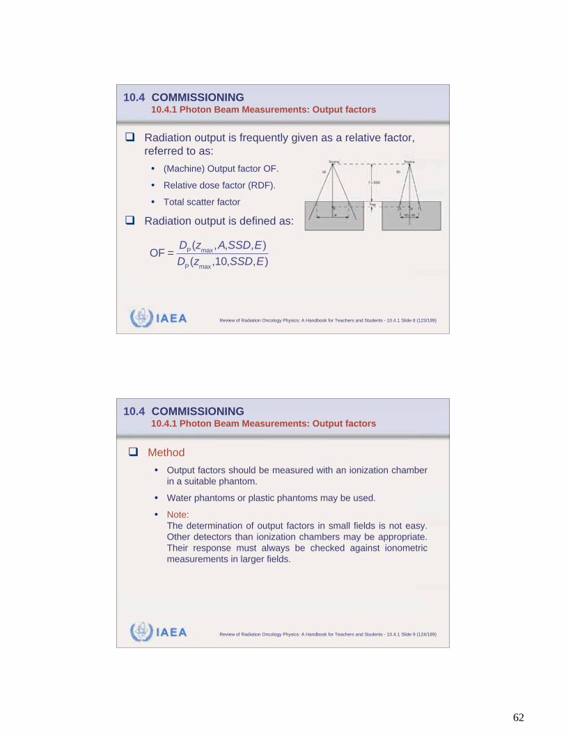
IAEA Review of Radiation Oncology Physics: A Handbook for Teachers and Students - 10.4.1 Slide 8 (123/189)
10.4 COMMISSIONING 10.4.1 Photon Beam Measurements: Output factors
Radiation output is frequently given as a relative factor,
referred to as:
• (Machine) Output factor OF.
• Relative dose factor (RDF).
• Total scatter factor
Radiation output is defined as:
OF =D
P(z
max,A,SSD,E)
DP(z
max,10,SSD,E)
IAEA Review of Radiation Oncology Physics: A Handbook for Teachers and Students - 10.4.1 Slide 9 (124/189)
10.4 COMMISSIONING 10.4.1 Photon Beam Measurements: Output factors
Method
• Output factors should be measured with an ionization chamber
in a suitable phantom.
• Water phantoms or plastic phantoms may be used.
• Note:
The determination of output factors in small fields is not easy.
Other detectors than ionization chambers may be appropriate.
Their response must always be checked against ionometric
measurements in larger fields.
63
IAEA Review of Radiation Oncology Physics: A Handbook for Teachers and Students - 10.4.1 Slide 10 (125/189)
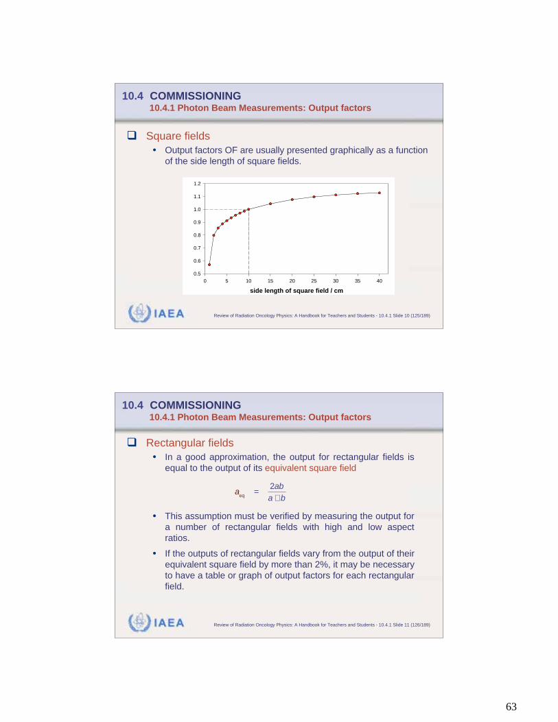
10.4 COMMISSIONING 10.4.1 Photon Beam Measurements: Output factors
Square fields
• Output factors OF are usually presented graphically as a function
of the side length of square fields.
side length of square field / cm
0 5 10 15 20 25 30 35 40
0.5
0.6
0.7
0.8
0.9
1.0
1.1
1.2
IAEA Review of Radiation Oncology Physics: A Handbook for Teachers and Students - 10.4.1 Slide 11 (126/189)
10.4 COMMISSIONING 10.4.1 Photon Beam Measurements: Output factors
Rectangular fields
• In a good approximation, the output for rectangular fields is
equal to the output of its equivalent square field
• This assumption must be verified by measuring the output for
a number of rectangular fields with high and low aspect
ratios.
• If the outputs of rectangular fields vary from the output of their
equivalent square field by more than 2%, it may be necessary
to have a table or graph of output factors for each rectangular
field.
a
eq=
2ab
a + b
64
IAEA Review of Radiation Oncology Physics: A Handbook for Teachers and Students - 10.4.1 Slide 12 (127/189)
10.4 COMMISSIONING 10.4.1 Photon Beam Measurements: Output factors
Rectangular fields (cont.)
• This matter can be further complicated since linacs may exhibit a
dependence on jaw orientation.
• For example, the output of a rectangular field may depend on
whether or not the upper or lower jaw forms the long side of the
field.
• This effect is sometimes referred to as the collimator exchange
effect and should be investigated as part of the commissioning
process.
IAEA Review of Radiation Oncology Physics: A Handbook for Teachers and Students - 10.4.1 Slide 13 (128/189)
10.4 COMMISSIONING 10.4.1 Photon Beam Measurements: Output factors
Asymmetric fields
• Treatment with asymmetric fields requires knowledge of the change
of output factors for these fields.
65
IAEA Review of Radiation Oncology Physics: A Handbook for Teachers and Students - 10.4.1 Slide 14 (129/189)
10.4 COMMISSIONING 10.4.1 Photon Beam Measurements: Output factors
Asymmetric fields
• The output factors for asymmetric fields can be approximated by:
OFa,y is the output factor with asymmetric collimator opening.
OFs is the output factor with symmetric collimator opening.
y is the displacement of the central ray of the asymmetric
field from that of the symmetric field.
OAR(zmax,y) is the off axis ratio measured at zmax and y centimeters
from the central axis of the symmetric field.
OF
a,y= OF
sOAR(z
max,y)
IAEA Review of Radiation Oncology Physics: A Handbook for Teachers and Students - 10.4.1 Slide 15 (130/189)
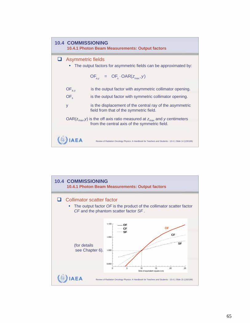
10.4 COMMISSIONING 10.4.1 Photon Beam Measurements: Output factors
Collimator scatter factor
• The output factor OF is the product of the collimator scatter factor
CF and the phantom scatter factor SF .
(for details
see Chapter 6).
OF
CF
SF
OF
CF
SF
66
IAEA Review of Radiation Oncology Physics: A Handbook for Teachers and Students - 10.4.1 Slide 16 (131/189)
10.4 COMMISSIONING 10.4.1 Photon Beam Measurements: Output factors
Collimator scatter factor
• Collimator scatter factor is measured “in air” with a build-up cap
large enough to provide electronic equilibrium.
• Use of a build-up cap made of higher density material
(aluminum or copper) may be appropriate.
• Alternatively, collimator scatter factor may be determined by
placing the ionization chamber at an extended SSD.
IAEA Review of Radiation Oncology Physics: A Handbook for Teachers and Students - 10.4.1 Slide 17 (132/189)
10.4 COMMISSIONING 10.4.1 Photon Beam Measurements: Output factors
Phantom scatter factor
• Since output factor OF and collimator scatter factor CF can be
measured, and:
the phantom scatter factor SF may be simply found by dividing
the output factor by the collimator scatter factor.
OF = CF SF

67
IAEA Review of Radiation Oncology Physics: A Handbook for Teachers and Students - 10.4.1 Slide 18 (133/189)
10.4 COMMISSIONING 10.4.1 Photon Beam Measurements: Blocking tray factors
Purpose
• Shielding blocks are frequentlyused to protect normal criticalstructures within the irradiatedarea. These blocks are supportedon a plastic tray to correctlyposition them within the radiationfield.
• Since this tray attenuates theradiation beam, the amount ofbeam attenuation denoted asblocking tray factors must beknown to calculate the dosereceived by the patient.
IAEA Review of Radiation Oncology Physics: A Handbook for Teachers and Students - 10.4.1 Slide 19 (134/189)
10.4 COMMISSIONING 10.4.1 Photon Beam Measurements: Blocking tray factors
Method
• The attenuation for solid trays is measured by placing an
ionization chamber on the central axis of the beam at
5 cm depth in phantom in a 10 10 cm2 field.
• The ratio of the ionization chamber signal with the tray in the
beam to the signal without the tray is the blocking tray
transmission factor.
• Although the tray transmission factor should be measured for
several depths and field sizes this factor usually has only a weak
dependence on these variables and typically one may use one
value for all depths and field sizes.

68
IAEA Review of Radiation Oncology Physics: A Handbook for Teachers and Students - 10.4.1 Slide 20 (135/189)
10.4 COMMISSIONING 10.4.1 Photon Beam Measurements: Multileaf collimators
Purpose
• On most current treatment machines multileaf collimators (MLCs)
are finding widespread application for conventional field shaping as
a replacement for shielding blocks.
• Additional data on MLC fields is required, such as:
• Central axis percentage depth doses.
• Penumbra of the MLC fields.
• Output factors.
• Leakage through and between the leaves.
IAEA Review of Radiation Oncology Physics: A Handbook for Teachers and Students - 10.4.1 Slide 21 (136/189)
10.4 COMMISSIONING 10.4.1 Photon Beam Measurements: Multileaf collimators
Central axis percentage depth doses
• PDDs should again be measured in a water phantom.
Typically these values are not significantly different from those
for fields defined with the collimator jaws.
Penumbra
• Penumbra should be measured for both the leaf ends and leaf
edges.
• Generally, the MLC penumbra is within 2 mm of the
penumbra of fields defined with the collimator jaws, with the
greatest difference being for singly focused MLC fields not
centered on the collimator axis of rotation.
69
IAEA Review of Radiation Oncology Physics: A Handbook for Teachers and Students - 10.4.1 Slide 22 (137/189)
10.4 COMMISSIONING 10.4.1 Photon Beam Measurements: Multileaf collimators
Output factor for multileaf collimators
• The output factor for MLC fields is generally given by:
where CF is the collimator scatter factor.
SF is the phantom scatter factor.
• The relationship for the MLC output factor must be verified for
each radiotherapy machine.
OF
MLC= CF
MLC settingSF
irradiated area
IAEA Review of Radiation Oncology Physics: A Handbook for Teachers and Students - 10.4.1 Slide 23 (138/189)
10.4 COMMISSIONING 10.4.1 Photon Beam Measurements: Multileaf collimators
MLC Leakage
• Leakage through the MLC consists of:
• Transmission through the leaves
• Leakage between the leaves.

70
IAEA Review of Radiation Oncology Physics: A Handbook for Teachers and Students - 10.4.1 Slide 24 (139/189)
10.4 COMMISSIONING 10.4.1 Photon Beam Measurements: Multileaf collimators
MLC Leakage
• Leakage can be determinedusing film dosimetry.
• The method consists ofcomparing a film obtained withtotally closed MLC leaves (andhence must be exposed with alarge number of MU) with that ofan open reference field.
• Typical values of MLC leakagethrough the leaves are in therange of 3% to 5% of theisocenter dose.
IAEA Review of Radiation Oncology Physics: A Handbook for Teachers and Students - 10.4.1 Slide 25 (140/189)
10.4 COMMISSIONING 10.4.1 Photon Beam Measurements: Wedge transmission factors
Definition and specification
• The central axis wedge transmission factor is the ratio of the
dose at a specified depth on the central axis of a specified field
size with the wedge in the beam to the dose for the same
conditions without the wedge in the beam.
• Frequently, the wedge factor determined for one field size at
one depth is used for all wedged fields and all depths.
• This simplification must be verified for a number of depths and
field sizes.
71
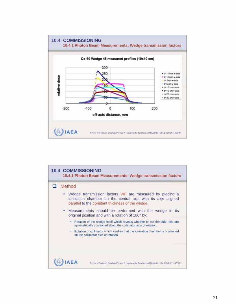
IAEA Review of Radiation Oncology Physics: A Handbook for Teachers and Students - 10.4.1 Slide 26 (141/189)
10.4 COMMISSIONING 10.4.1 Photon Beam Measurements: Wedge transmission factors
IAEA Review of Radiation Oncology Physics: A Handbook for Teachers and Students - 10.4.1 Slide 27 (142/189)
10.4 COMMISSIONING 10.4.1 Photon Beam Measurements: Wedge transmission factors
Method
• Wedge transmission factors WF are measured by placing a
ionization chamber on the central axis with its axis aligned
parallel to the constant thickness of the wedge.
• Measurements should be performed with the wedge in its
original position and with a rotation of 180° by:
• Rotation of the wedge itself which reveals whether or not the side rails are
symmetrically positioned about the collimator axis of rotation.
• Rotation of collimator which verifies that the ionization chamber is positioned
on the collimator axis of rotation.
72
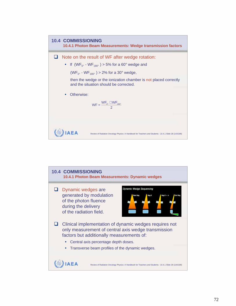
IAEA Review of Radiation Oncology Physics: A Handbook for Teachers and Students - 10.4.1 Slide 28 (143/189)
10.4 COMMISSIONING 10.4.1 Photon Beam Measurements: Wedge transmission factors
Note on the result of WF after wedge rotation:
• If (WF0° - WF180° ) > 5% for a 60° wedge and
(WF0° - WF180° ) > 2% for a 30° wedge,
then the wedge or the ionization chamber is not placed correctly
and the situation should be corrected.
• Otherwise:
WF =
WF0°
+ WF180°
2
IAEA Review of Radiation Oncology Physics: A Handbook for Teachers and Students - 10.4.1 Slide 29 (144/189)
10.4 COMMISSIONING 10.4.1 Photon Beam Measurements: Dynamic wedges
Dynamic wedges are
generated by modulation
of the photon fluence
during the delivery
of the radiation field.
Clinical implementation of dynamic wedges requires not
only measurement of central axis wedge transmission
factors but additionally measurements of:
• Central axis percentage depth doses.
• Transverse beam profiles of the dynamic wedges.
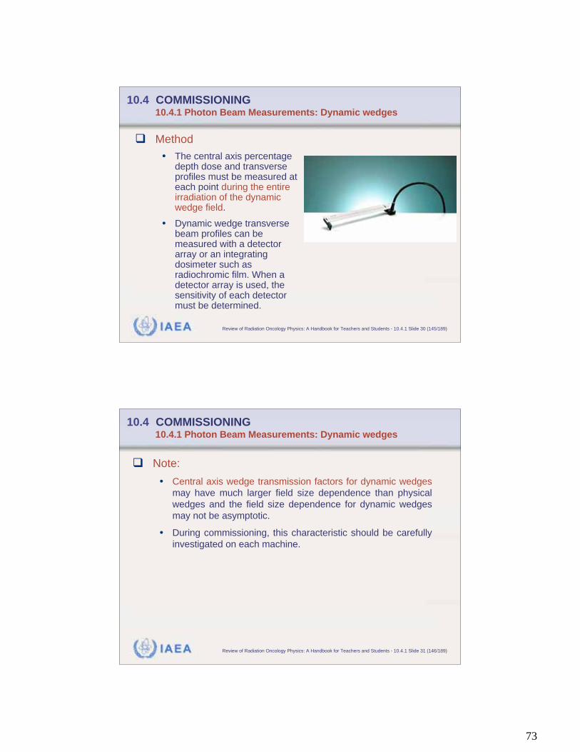
73
IAEA Review of Radiation Oncology Physics: A Handbook for Teachers and Students - 10.4.1 Slide 30 (145/189)
10.4 COMMISSIONING 10.4.1 Photon Beam Measurements: Dynamic wedges
Method
• The central axis percentagedepth dose and transverseprofiles must be measured ateach point during the entireirradiation of the dynamicwedge field.
• Dynamic wedge transversebeam profiles can bemeasured with a detectorarray or an integratingdosimeter such asradiochromic film. When adetector array is used, thesensitivity of each detectormust be determined.
IAEA Review of Radiation Oncology Physics: A Handbook for Teachers and Students - 10.4.1 Slide 31 (146/189)
10.4 COMMISSIONING 10.4.1 Photon Beam Measurements: Dynamic wedges
Note:
• Central axis wedge transmission factors for dynamic wedges
may have much larger field size dependence than physical
wedges and the field size dependence for dynamic wedges
may not be asymptotic.
• During commissioning, this characteristic should be carefully
investigated on each machine.
74
IAEA Review of Radiation Oncology Physics: A Handbook for Teachers and Students - 10.4.1 Slide 32 (147/189)
10.4 COMMISSIONING 10.4.1 Photon Beam Measurements: Transverse beam profiles
Purpose
• For the calculation of 2-D and 3-D dose distributions, off-axis
dose profiles are required in conjunction with central axis
data.
• The number of profiles and the depths at which these profiles
are measured will depend on the requirements of the
treatment planning system.
• Frequently off-axis data are normalized to the dose on the
central axis at the same depth.
• These data are referred to as off-axis ratios (OAR).
IAEA Review of Radiation Oncology Physics: A Handbook for Teachers and Students - 10.4.1 Slide 33 (148/189)
10.4 COMMISSIONING 10.4.1 Photon Beam Measurements: Transverse beam profiles
Method
• A water phantom (or radiation field analyzer) that scans a small
ionization chamber or diode in the radiation field is ideal for the
measurement of such data.
• Note: In addition to those transverse beam profiles on which the
beam model is determined, further profiles (including such of
wedge fields) should be measured to verify the accuracy of the
treatment planning system algorithms.
75
IAEA Review of Radiation Oncology Physics: A Handbook for Teachers and Students - 10.4.1 Slide 34 (149/189)
10.4 COMMISSIONING 10.4.1 Photon Beam Measurements: Transverse beam profiles
10MV, TPS *******, OPEN, 10x10 cm2, d = 200 mm, error bars 1%, 2mm
0
20
40
60
80
100
-100 -80 -60 -40 -20 0 20 40 60 80 100
Off axis, mm
Re
lati
ve
do
se
, %
TPS Phantom
10MV, TPS ******, OPEN, 10x10 cm2, d = 50 mm, error bars 1%, 2mm
0
20
40
60
80
100
-100 -80 -60 -40 -20 0 20 40 60 80 100
Off axis, mm
Re
lati
ve
do
se
, %
TPS Phantom
IAEA Review of Radiation Oncology Physics: A Handbook for Teachers and Students - 10.4.1 Slide 35 (150/189)
10.4 COMMISSIONING 10.4.1 Photon Beam Measurements: Entrance/interface dose
Purpose
• Knowledge of dose values at interfaces is important in a variety of
clinical situations.
• Examples:
• Entrance dose between the patient surface and zmax.
• Interfaces at small air cavities such as the nasopharynx.
• At the exit surface of the patient.
• At bone–soft tissue interfaces.
• Interfaces between a metallic prosthesis and tissue.
76
IAEA Review of Radiation Oncology Physics: A Handbook for Teachers and Students - 10.4.1 Slide 36 (151/189)
10.4 COMMISSIONING 10.4.1 Photon Beam Measurements: Entrance/interface dose
Method
• Rapidly changing dose gradients are typical in interface
situations.
• Under such condition, thin window parallel plate chamber is
adequate to perform measurements.
• Note:
Measurements with a thin window parallel plate chamber may be
difficult to perform in a water phantom because of the need to
waterproof the chamber and to avoid defor-mation of the window
by hydrostatic pressure.
IAEA Review of Radiation Oncology Physics: A Handbook for Teachers and Students - 10.4.1 Slide 37 (152/189)
10.4 COMMISSIONING 10.4.1 Photon Beam Measurements: Entrance/interface dose
Method (continued)
• Interface measurements are typically carried out in a plastic
phantom in a constant SSD geometry.
• First measurement is made with no buildup material.
• Next depth is measured by moving the appropriate sheet of
buildup material from bottom to the top of the phantom, etc.
• This maintains a constant SSD as buildup material is added.
Constant SSDIC
1. measurement 2. measurement 3. measurement
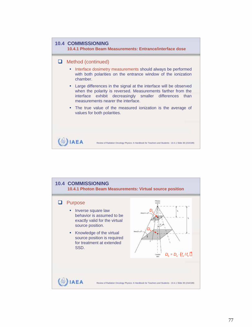
77
IAEA Review of Radiation Oncology Physics: A Handbook for Teachers and Students - 10.4.1 Slide 38 (153/189)
10.4 COMMISSIONING 10.4.1 Photon Beam Measurements: Entrance/interface dose
Method (continued)
• Interface dosimetry measurements should always be performed
with both polarities on the entrance window of the ionization
chamber.
• Large differences in the signal at the interface will be observed
when the polarity is reversed. Measurements farther from the
interface exhibit decreasingly smaller differences than
measurements nearer the interface.
• The true value of the measured ionization is the average of
values for both polarities.
IAEA Review of Radiation Oncology Physics: A Handbook for Teachers and Students - 10.4.1 Slide 39 (154/189)
10.4 COMMISSIONING 10.4.1 Photon Beam Measurements: Virtual source position
Purpose
• Inverse square law
behavior is assumed to be
exactly valid for the virtual
source position.
• Knowledge of the virtual
source position is required
for treatment at extended
SSD.
( )2
b a a b/D D f f=
bD
aD
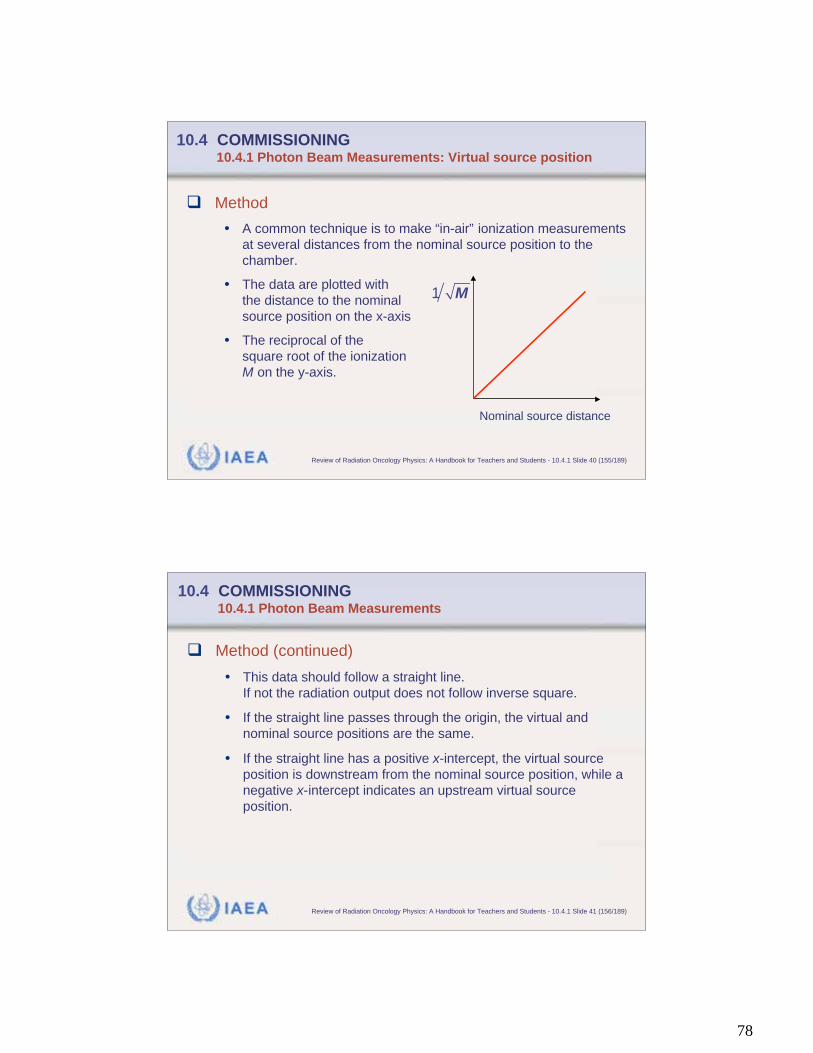
78
IAEA Review of Radiation Oncology Physics: A Handbook for Teachers and Students - 10.4.1 Slide 40 (155/189)
10.4 COMMISSIONING 10.4.1 Photon Beam Measurements: Virtual source position
Method
• A common technique is to make “in-air” ionization measurements
at several distances from the nominal source position to the
chamber.
• The data are plotted with
the distance to the nominal
source position on the x-axis
• The reciprocal of the
square root of the ionization
M on the y-axis.
Nominal source distance
1 M
IAEA Review of Radiation Oncology Physics: A Handbook for Teachers and Students - 10.4.1 Slide 41 (156/189)
10.4 COMMISSIONING 10.4.1 Photon Beam Measurements
Method (continued)
• This data should follow a straight line.
If not the radiation output does not follow inverse square.
• If the straight line passes through the origin, the virtual and
nominal source positions are the same.
• If the straight line has a positive x-intercept, the virtual source
position is downstream from the nominal source position, while a
negative x-intercept indicates an upstream virtual source
position.
79
IAEA Review of Radiation Oncology Physics: A Handbook for Teachers and Students - 10.4.2 Slide 1 (157/189)
10.4 COMMISSIONING 10.4.2 Electron Beam Measurements
Commissioning procedures for acquiring electron beam
data are similar (but not identical) to those used for photon
beams.
Data to be acquired include:
• Central axis percentage depth doses (PDD)
• Output factors
• Transverse beam profiles
• Corrections for extended SSD applications
IAEA Review of Radiation Oncology Physics: A Handbook for Teachers and Students - 10.4.2 Slide 2 (158/189)
10.4 COMMISSIONING 10.4.2 Electron Beam Measurements: PDD
Method
• Central axis percentage depth doses are preferable measured in
a water phantom.
• For measurements, plane-parallel ionization chambers with the
effective point of measurement placed at nominal depth are
highly recommended.
• Note:
The effective point of measurement of a plane-parallel chamber
is on the inner surface of the entrance window, at the center of
the window for all beam qualities and depths.
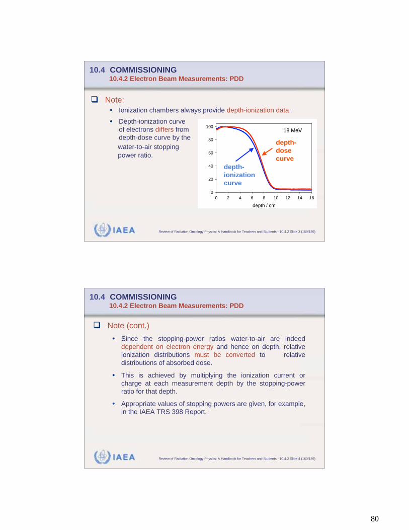
80
IAEA Review of Radiation Oncology Physics: A Handbook for Teachers and Students - 10.4.2 Slide 3 (159/189)
10.4 COMMISSIONING 10.4.2 Electron Beam Measurements: PDD
Note:
• Ionization chambers always provide depth-ionization data.
• Depth-ionization curve
of electrons differs from
depth-dose curve by the
water-to-air stopping
power ratio.
18 MeV
depth / cm
0 2 4 6 8 10 12 14 16
0
20
40
60
80
100
depth-
ionization
curve
depth-
dose
curve
IAEA Review of Radiation Oncology Physics: A Handbook for Teachers and Students - 10.4.2 Slide 4 (160/189)
10.4 COMMISSIONING 10.4.2 Electron Beam Measurements: PDD
Note (cont.)
• Since the stopping-power ratios water-to-air are indeed
dependent on electron energy and hence on depth, relative
ionization distributions must be converted to relative
distributions of absorbed dose.
• This is achieved by multiplying the ionization current or
charge at each measurement depth by the stopping-power
ratio for that depth.
• Appropriate values of stopping powers are given, for example,
in the IAEA TRS 398 Report.
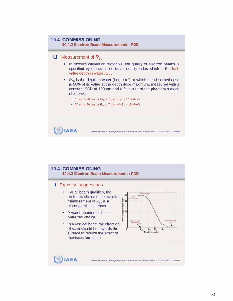
81
IAEA Review of Radiation Oncology Physics: A Handbook for Teachers and Students - 10.4.2 Slide 5 (161/189)
10.4 COMMISSIONING 10.4.2 Electron Beam Measurements: PDD
Measurement of R50
• In modern calibration protocols, the quality of electron beams is
specified by the so-called beam quality index which is the half-
value depth in water R50 .
• R50 is the depth in water (in g cm-2) at which the absorbed dose
is 50% of its value at the depth dose maximum, measured with a
constant SSD of 100 cm and a field size at the phantom surface
of at least
• 10 cm x 10 cm for R50 7 g cm-2 (E0 16 MeV).
• 20 cm x 20 cm for R50 > 7 g cm-2 (E0 > 16 MeV).
IAEA Review of Radiation Oncology Physics: A Handbook for Teachers and Students - 10.4.2 Slide 6 (162/189)
10.4 COMMISSIONING 10.4.2 Electron Beam Measurements: PDD
Practical suggestions
• For all beam qualities, the
preferred choice of detector for
measurement of R50 is a
plane-parallel chamber.
• A water phantom is the
preferred choice.
• In a vertical beam the direction
of scan should be towards the
surface to reduce the effect of
meniscus formation.
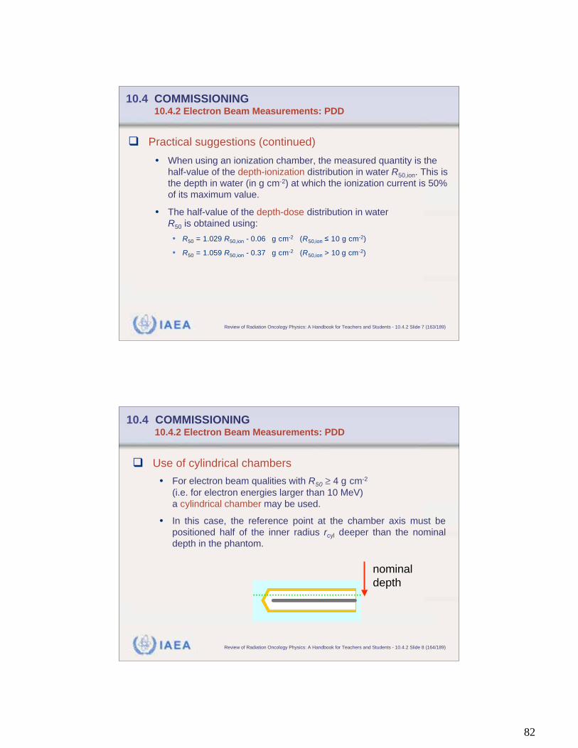
82
IAEA Review of Radiation Oncology Physics: A Handbook for Teachers and Students - 10.4.2 Slide 7 (163/189)
10.4 COMMISSIONING 10.4.2 Electron Beam Measurements: PDD
Practical suggestions (continued)
• When using an ionization chamber, the measured quantity is the
half-value of the depth-ionization distribution in water R50,ion. This is
the depth in water (in g cm-2) at which the ionization current is 50%
of its maximum value.
• The half-value of the depth-dose distribution in water
R50 is obtained using:
• R50 = 1.029 R50,ion - 0.06 g cm-2 (R50,ion 10 g cm-2)
• R50 = 1.059 R50,ion - 0.37 g cm-2 (R50,ion > 10 g cm-2)
IAEA Review of Radiation Oncology Physics: A Handbook for Teachers and Students - 10.4.2 Slide 8 (164/189)
10.4 COMMISSIONING 10.4.2 Electron Beam Measurements: PDD
Use of cylindrical chambers
• For electron beam qualities with R50 4 g cm-2
(i.e. for electron energies larger than 10 MeV)
a cylindrical chamber may be used.
• In this case, the reference point at the chamber axis must be
positioned half of the inner radius rcyl deeper than the nominal
depth in the phantom.
nominal
depth
83
IAEA Review of Radiation Oncology Physics: A Handbook for Teachers and Students - 10.4.2 Slide 9 (165/189)
10.4 COMMISSIONING 10.4.2 Electron Beam Measurements: PDD
Use of plastic phantoms
• For beam qualities R50 < 4 g cm-2
(i.e., for electron energies smaller than 10 MeV)
a plastic phantom may be used.
• In this case, each measurement depth in plastic must be scaled
using
zw = zpl cpl in g cm-2 (since zpl in g cm-2)
to give the appropriate depth in water.
(Table from
IAEA TRS 398)
0.922White polystyrene
0.941PMMA
0.949Solid water (RMI-457)
cplPlastic phantom
IAEA Review of Radiation Oncology Physics: A Handbook for Teachers and Students - 10.4.2 Slide 10 (166/189)
10.4 COMMISSIONING 10.4.2 Electron Beam Measurements: PDD
Use of plastic phantoms (cont.)
• In addition, the dosimeter reading M at each depth must also be
scaled using
M = Mpl hpl
• For depths beyond zref,pl it is acceptable to use the value for hpl
at zref,pl derived from the Table below.
• At shallower depths, this value should be decreased linearly to
a value of unity at zero depth.
(Table from
IAEA TRS 398)
1.019White polystyrene
1.009PMMA
1.008Solid water (RMI-457)
hplPlastic phantom
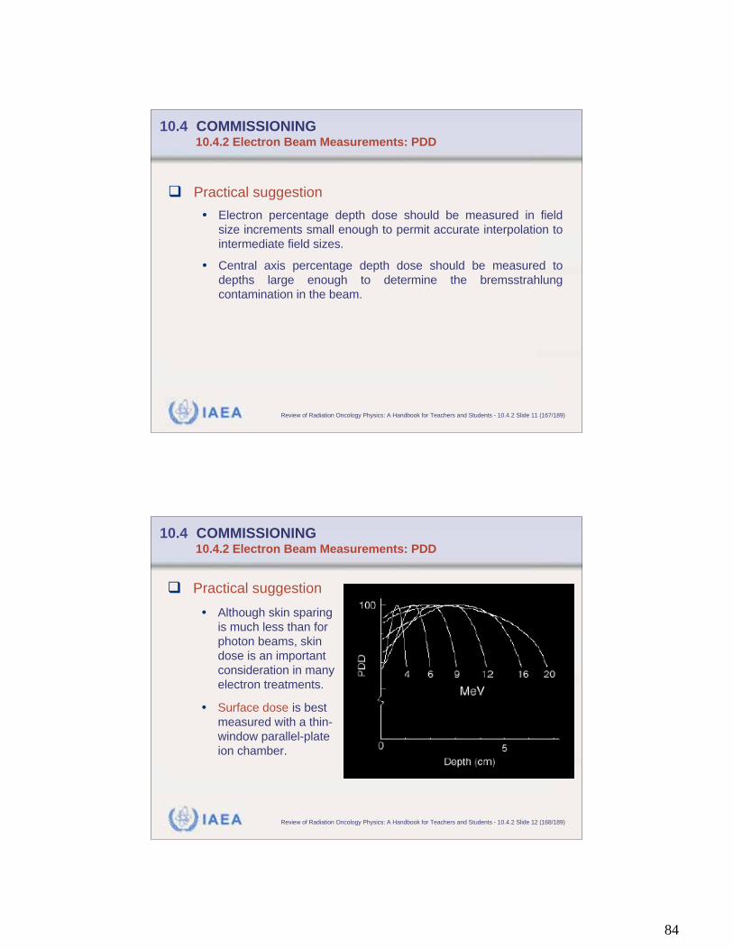
84
IAEA Review of Radiation Oncology Physics: A Handbook for Teachers and Students - 10.4.2 Slide 11 (167/189)
10.4 COMMISSIONING 10.4.2 Electron Beam Measurements: PDD
Practical suggestion
• Electron percentage depth dose should be measured in field
size increments small enough to permit accurate interpolation to
intermediate field sizes.
• Central axis percentage depth dose should be measured to
depths large enough to determine the bremsstrahlung
contamination in the beam.
IAEA Review of Radiation Oncology Physics: A Handbook for Teachers and Students - 10.4.2 Slide 12 (168/189)
10.4 COMMISSIONING 10.4.2 Electron Beam Measurements: PDD
Practical suggestion
• Although skin sparing
is much less than for
photon beams, skin
dose is an important
consideration in many
electron treatments.
• Surface dose is best
measured with a thin-
window parallel-plate
ion chamber.
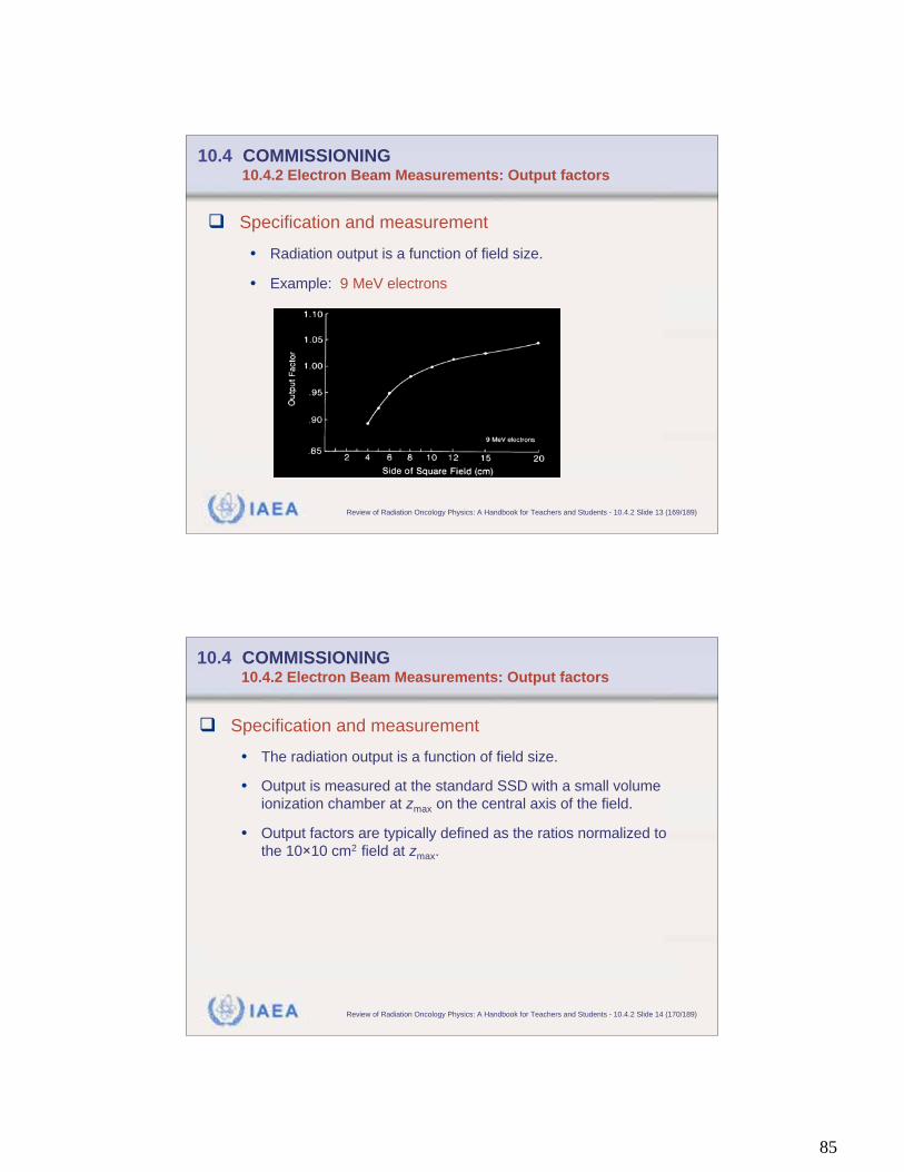
85
IAEA Review of Radiation Oncology Physics: A Handbook for Teachers and Students - 10.4.2 Slide 13 (169/189)
10.4 COMMISSIONING 10.4.2 Electron Beam Measurements: Output factors
Specification and measurement
• Radiation output is a function of field size.
• Example: 9 MeV electrons
IAEA Review of Radiation Oncology Physics: A Handbook for Teachers and Students - 10.4.2 Slide 14 (170/189)
10.4 COMMISSIONING 10.4.2 Electron Beam Measurements: Output factors
Specification and measurement
• The radiation output is a function of field size.
• Output is measured at the standard SSD with a small volume
ionization chamber at zmax on the central axis of the field.
• Output factors are typically defined as the ratios normalized to
the 10 10 cm2 field at zmax.
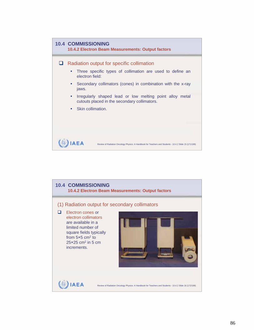
86
IAEA Review of Radiation Oncology Physics: A Handbook for Teachers and Students - 10.4.2 Slide 15 (171/189)
10.4 COMMISSIONING 10.4.2 Electron Beam Measurements: Output factors
Radiation output for specific collimation
• Three specific types of collimation are used to define an
electron field:
• Secondary collimators (cones) in combination with the x-ray
jaws.
• Irregularly shaped lead or low melting point alloy metal
cutouts placed in the secondary collimators.
• Skin collimation.
IAEA Review of Radiation Oncology Physics: A Handbook for Teachers and Students - 10.4.2 Slide 16 (172/189)
10.4 COMMISSIONING 10.4.2 Electron Beam Measurements: Output factors
(1) Radiation output for secondary collimators
Electron cones or
electron collimators
are available in a
limited number of
square fields typically
from 5 5 cm2 to
25 25 cm2 in 5 cm
increments.

87
IAEA Review of Radiation Oncology Physics: A Handbook for Teachers and Students - 10.4.2 Slide 17 (173/189)
10.4 COMMISSIONING 10.4.2 Electron Beam Measurements: Output factors
(1) Radiation output for secondary collimators
The purpose of the cone depends on the manufacturer. Some use
cones only to reduce the penumbra, others use the cone to scatter
electrons off the side of the cone to improve field flatness.
The output for each cone must be determined for all electron
energies. These values are frequently referred to as cone ratios
rather than output factors.
IAEA Review of Radiation Oncology Physics: A Handbook for Teachers and Students - 10.4.2 Slide 18 (174/189)
10.4 COMMISSIONING 10.4.2 Electron Beam Measurements: Output factors
(1) Radiation output for secondary collimators
For rectangular fields formed by placing inserts in cones the
equivalent square can be approximated with a square root method.
The validity of this method should be checked on each machine for
which the approximation is used.
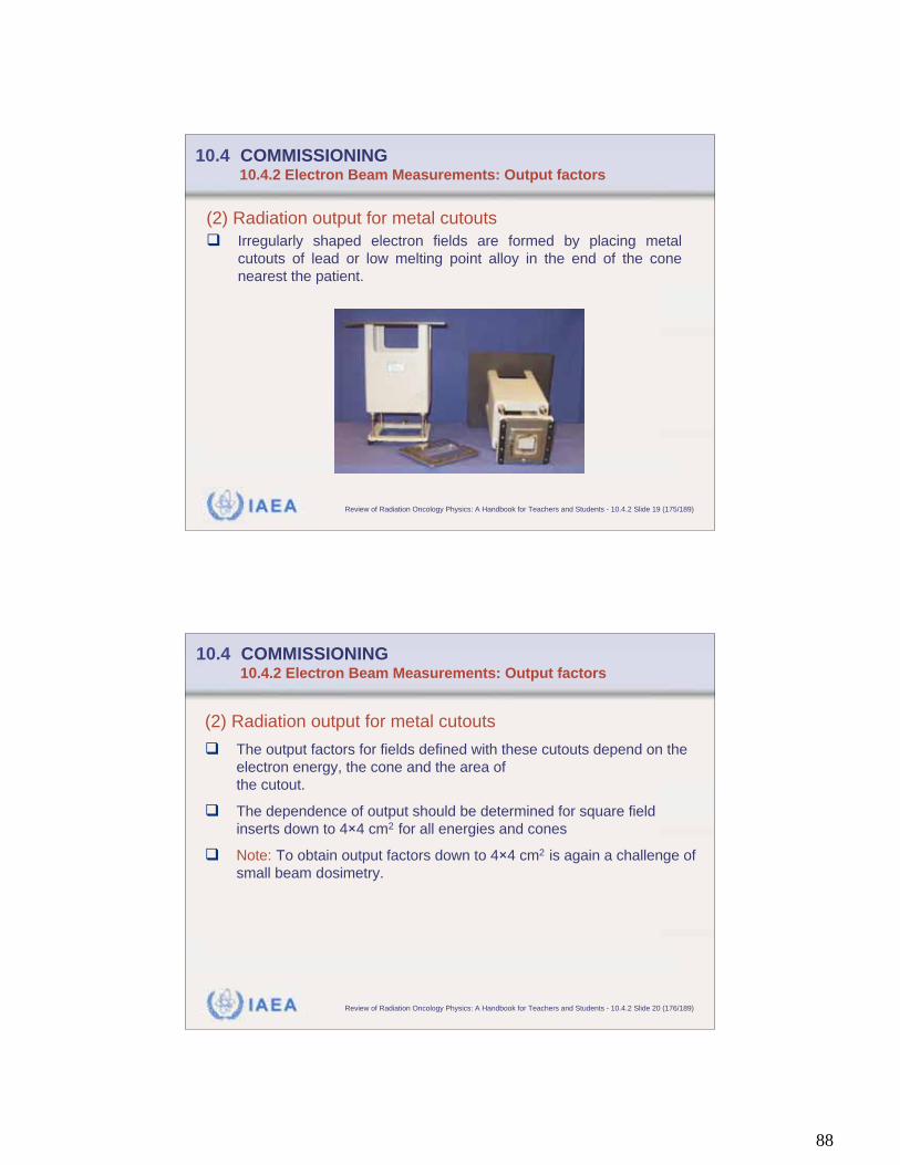
88
IAEA Review of Radiation Oncology Physics: A Handbook for Teachers and Students - 10.4.2 Slide 19 (175/189)
10.4 COMMISSIONING 10.4.2 Electron Beam Measurements: Output factors
(2) Radiation output for metal cutouts
Irregularly shaped electron fields are formed by placing metal
cutouts of lead or low melting point alloy in the end of the cone
nearest the patient.
IAEA Review of Radiation Oncology Physics: A Handbook for Teachers and Students - 10.4.2 Slide 20 (176/189)
10.4 COMMISSIONING 10.4.2 Electron Beam Measurements: Output factors
(2) Radiation output for metal cutouts
The output factors for fields defined with these cutouts depend on the
electron energy, the cone and the area of
the cutout.
The dependence of output should be determined for square field
inserts down to 4 4 cm2 for all energies and cones
Note: To obtain output factors down to 4 4 cm2 is again a challenge of
small beam dosimetry.
89
IAEA Review of Radiation Oncology Physics: A Handbook for Teachers and Students - 10.4.2 Slide 21 (177/189)
10.4 COMMISSIONING 10.4.2 Electron Beam Measurements: Output factors
(2) Radiation output for small fields
The output factor is the ratio of dose at zmax for the small field to dose
at zmax for the 10 10 cm2 field.
Since zmax shifts toward the surface for electron fields with dimensions
smaller than the range of the electrons, it must be determined for
each small field size when measuring output factors.
For ionometric data this requires converting the ionization to dose at
each zmax before determining the output factor, rather than simply
taking the ratio of the ionizations.
IAEA Review of Radiation Oncology Physics: A Handbook for Teachers and Students - 10.4.2 Slide 22 (178/189)
10.4 COMMISSIONING 10.4.2 Electron Beam Measurements: Output factors
Film is an alternate solution. It can be exposed in a
polystyrene or water equivalent plastic phantom in a
parallel orientation to the central axis of the beam.
• One film should be exposed to a 10 10 cm2 field.
• Another film to the smaller field.
The films should be scanned to find the central axis
zmax for each field.
90
IAEA Review of Radiation Oncology Physics: A Handbook for Teachers and Students - 10.4.2 Slide 23 (179/189)
10.4 COMMISSIONING 10.4.2 Electron Beam Measurements: Output factors
(3) Radiation output for skin collimation
Skin collimation is accomplished by using a special insert in a larger
electron cone. The skin collimation then collimates this larger field to
the treatment area.
Skin collimation is used:
• To minimize penumbra for very small electron fields.
• To protect critical structures near the treatment area.
• To restore the penumbra when treatment at extended distance is
required.
IAEA Review of Radiation Oncology Physics: A Handbook for Teachers and Students - 10.4.2 Slide 24 (180/189)
10.4 COMMISSIONING 10.4.2 Electron Beam Measurements: Output factors
(3) Radiation output for skin collimation
If skin collimation is clinically applied, particular commis-sioning
tests may be required.
As for any small field, skin collimation may affect the percent depth
dose as well as the penumbra, if the dimensions of the treatment
field are smaller than the electron range.
In this case, PDD values and output factors must be measured.
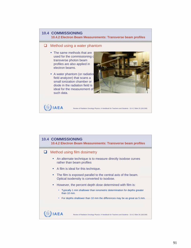
91
IAEA Review of Radiation Oncology Physics: A Handbook for Teachers and Students - 10.4.2 Slide 25 (181/189)
10.4 COMMISSIONING 10.4.2 Electron Beam Measurements: Transverse beam profiles
• The same methods that are
used for the commissioning of
transverse photon beam
profiles are also applied in
electron beams.
• A water phantom (or radiation
field analyzer) that scans a
small ionization chamber or
diode in the radiation field is
ideal for the measurement of
such data.
Method using a water phantom
IAEA Review of Radiation Oncology Physics: A Handbook for Teachers and Students - 10.4.2 Slide 26 (182/189)
10.4 COMMISSIONING 10.4.2 Electron Beam Measurements: Transverse beam profiles
Method using film dosimetry
• An alternate technique is to measure directly isodose curves
rather than beam profiles
• A film is ideal for this technique.
• The film is exposed parallel to the central axis of the beam.
Optical isodensity is converted to isodose.
• However, the percent depth dose determined with film is:
• Typically 1 mm shallower than ionometric determination for depths greater
than 10 mm.
• For depths shallower than 10 mm the differences may be as great as 5 mm.

92
IAEA Review of Radiation Oncology Physics: A Handbook for Teachers and Students - 10.4.2 Slide 27 (183/189)
10.4 COMMISSIONING 10.4.2 Electron Beam Measurements: Extended SSD applications
Virtual source position
• Frequently, electron fields must be treated at extended
distances because the surface of the patient prevents
positioning the electron applicator at the normal treatment
distance.
• In this case, additional scattering in the extended air path
increases the penumbral width and decreases the output.
• Knowledge of the virtual electron source is therefore required
to predict these changes.
• Determination of the virtual source position is similar to the
verification of inverse square law for photons.
IAEA Review of Radiation Oncology Physics: A Handbook for Teachers and Students - 10.4.2 Slide 28 (184/189)
10.4 COMMISSIONING 10.4.2 Electron Beam Measurements: Extended SSD applications
Air gap correction factor
• Radiation output as predicted by the treatment planning
computers use the virtual source position to calculate the
divergence of the electron beams at extended SSDs.
• In addition to the inverse square factor, an air gap correction
factor is required to account for the additional scattering in the
extended air path.
• Air gap factor must be measured.
• Air gap correction factors depend on collimator design, electron
energy, field size and air gap. They are typically less than 2%.
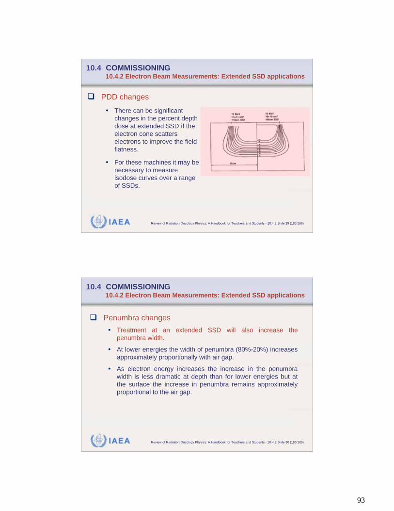
93
IAEA Review of Radiation Oncology Physics: A Handbook for Teachers and Students - 10.4.2 Slide 29 (185/189)
10.4 COMMISSIONING 10.4.2 Electron Beam Measurements: Extended SSD applications
PDD changes
• There can be significant
changes in the percent depth
dose at extended SSD if the
electron cone scatters
electrons to improve the field
flatness.
• For these machines it may be
necessary to measure
isodose curves over a range
of SSDs.
IAEA Review of Radiation Oncology Physics: A Handbook for Teachers and Students - 10.4.2 Slide 30 (186/189)
10.4 COMMISSIONING 10.4.2 Electron Beam Measurements: Extended SSD applications
Penumbra changes
• Treatment at an extended SSD will also increase the
penumbra width.
• At lower energies the width of penumbra (80%-20%) increases
approximately proportionally with air gap.
• As electron energy increases the increase in the penumbra
width is less dramatic at depth than for lower energies but at
the surface the increase in penumbra remains approximately
proportional to the air gap.
94
IAEA Review of Radiation Oncology Physics: A Handbook for Teachers and Students - 10.4.2 Slide 31 (187/189)
10.4 COMMISSIONING 10.4.2 Electron Beam Measurements: Extended SSD applications
Penumbra changes
• In order to evaluate the algorithms in the treatment planning
system in use, it is recommended to include a sample of
isodose curves measurements at extended SSDs during
commissioning.
• Note: The penumbra can be restored when treating at
extended distances by use of skin collimation.
IAEA Review of Radiation Oncology Physics: A Handbook for Teachers and Students - 10.5 Slide 1 (188/189)
10.5 TIME REQUIRED FOR COMMISSIONING
Following completion of the acceptance tests, the
completion of all the commissioning tasks, i.e., the
tasks associated with placing a treatment unit into
clinical service, can be estimated to require:
1.5 - 3 weeks per beam energy energy
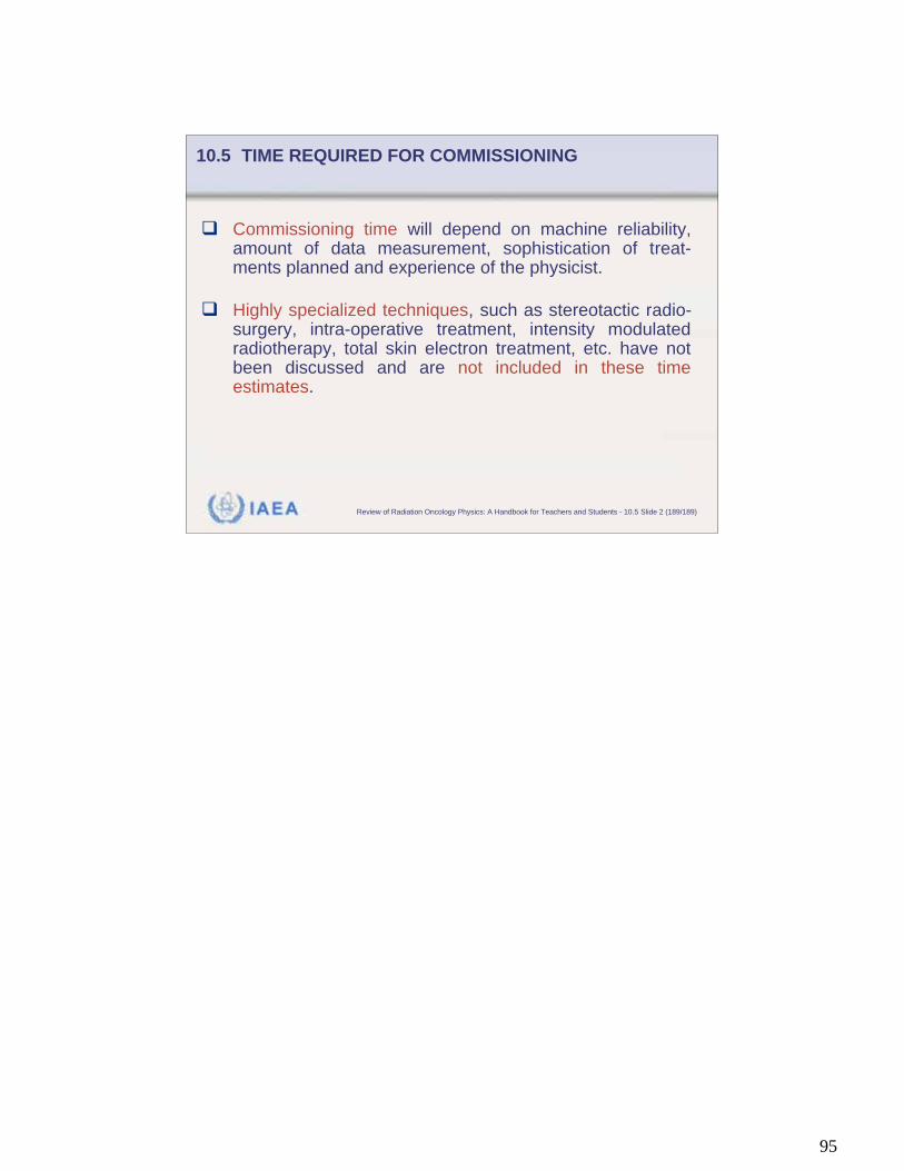
95
IAEA Review of Radiation Oncology Physics: A Handbook for Teachers and Students - 10.5 Slide 2 (189/189)
Commissioning time will depend on machine reliability,amount of data measurement, sophistication of treat-ments planned and experience of the physicist.
Highly specialized techniques, such as stereotactic radio-surgery, intra-operative treatment, intensity modulatedradiotherapy, total skin electron treatment, etc. have notbeen discussed and are not included in these timeestimates.
10.5 TIME REQUIRED FOR COMMISSIONING