chapter 1_ power electronics for renewable energy sources - alternative energy in power electronics
DESCRIPTION
114296039-TRANSCRIPT

C H A P T E R 1
Power Electronics forRenewable Energy SourcesC.V. Nayar; S.M. Islam; H. Dehbonei; K. Tan Department of Electrical and Computer
Engineering, Curtin University of Technology, Perth, Western Australia, Australia
H. Sharma Research Institute for Sustainable Energy, Murdoch University, Perth, Western
Australia, Australia
Abstract
This chapter focuses on solar photovoltaic and wind power. Stand‑alonePV energy system requires storage to meet the energy demand duringperiods of low solar irradiation and nighttime. Blocking diodes in serieswith PV modules are used to prevent the batteries from being dischargedthrough the PV cells at night when there is no sun available to generateenergy. Two of the main factors that have been identified as limitingcriteria for the cycle life of batteries in PV power systems are incompletecharging and prolonged operation at a low state of charge. The poweroutput of the PV array is sampled at an every definite sampling periodand compared with the previous value. Voltage source inverters areusually used in stand‑alone applications. They can be single phase orthree phase. There are three switching techniques commonly used: squarewave, quasi‑square wave, and pulse width modulation. Centrifugalpumps are used for low‑head applications especially if they are directlyinterfaced with the solar panels. Centrifugal pumps are designed forfixed‑head applications and the pressure difference generated increasesin relation to the speed of pump.
Keywords
Power electronics
Renewable energy sources
Photovoltaics
Wind
Solar
CHA P T E R O U T L I N E
1.1 Introduction 2
1.2 Power Electronics for Photovoltaic Power Systems 3
1.2.1 Basics of Photovoltaics 3
1.2.2 Types of PV Power Systems 6
1.2.3 Stand‑alone PV Systems 9
1.2.3.1 Battery Charging 9
1.2.3.2 Inverters for Stand‑alone PV Systems 15
1.2.3.3 Solar Water Pumping 18
PREVPreface⏮
NEXTChapter 2: Energy … ⏭
ὐ�
Alternative Energy in Power Electronics Recent
Topics
Tutorials
Highlights
Settings
Feedback(http://community.safaribooksonline.com)
Sign Out
Settings
9 days left in your trial. Subscribe.
Feedback(http://community.safaribooksonline.com/)
Sign Out
⚙

1.2.4 Hybrid Energy Systems 25
1.2.4.1 Series Configuration 26
1.2.4.2 Switched Configuration 27
1.2.4.3 Parallel Configuration 28
1.2.4.4 Control of Hybrid Energy Systems 30
1.2.5 Grid‑connected PV Systems 32
1.2.5.1 Inverters for Grid‑connected Applications 33
1.2.5.2 Inverter Classifications 33
1.2.5.3 Inverter Types 34
1.2.5.4 Power Control through PV Inverters 40
1.2.5.5 System Configurations 45
1.2.5.6 Grid‑compatible Inverters Characteristics 47
1.3 Power Electronics for Wind Power Systems 49
1.3.1 Basics of Wind Power 51
1.3.1.1 Types of Wind Turbines 53
1.3.1.2 Types of Wind Generators 54
1.3.2 Types of Wind Power Systems 58
1.3.3 Stand‑alone Wind Power Systems 58
1.3.3.1 Battery Charging with Stand‑alone Wind Energy System 58
1.3.3.2 Wind Turbine Charge Controller 58
1.3.4 Wind‑diesel Hybrid Systems 59
1.3.5 Grid‑connected Wind Energy Systems 60
1.3.5.1 Soft Starters for Induction Generators 61
1.3.6 Control of Wind Turbines 62
1.3.6.1 Fixed Speed Wind Turbines 62
1.3.6.2 Variable Speed Wind Turbines 65
1.3.6.3 Discretely Variable Speed Systems 66
1.3.6.4 Continuously Variable Speed Systems 67
1.3.6.5 Types of Generator Options for Variable Speed Wind TurbinesUsing Power Electronics 70
1.3.6.6 Isolated Grid Supply System with Multiple Wind Turbines 73
1.3.6.7 Power Electronics Technology Development 74
References 75
1.1 Introduction
The Kyoto agreement on global reduction of greenhouse gas emissionshas prompted renewed interest in renewable energy systems worldwide.Many renewable energy technologies today are well developed, reliable,and cost competitive with the conventional fuel generators. The cost ofrenewable energy technologies is on a falling trend and is expected to fallfurther as demand and production increases. There are many renewableenergy sources (RES) such as biomass, solar, wind, mini hydro and tidalpower. However, solar and wind energy systems make use of advancedpower electronics technologies and, therefore the focus in this chapterwill be on solar photovoltaic and wind power.
One of the advantages offered by (RES) is their potential to providesustainable electricity in areas not served by the conventional power grid.The growing market for renewable energy technologies has resulted in arapid growth in the need of power electronics. Most of the renewableenergy technologies produce DC power and hence power electronics andcontrol equipment are required to convert the DC into AC power.
Inverters are used to convert DC to AC. There are two types of inverters:(a) stand‑alone or (b) grid‑connected. Both types have several similaritiesbut are different in terms of control functions. A stand‑alone inverter isused in off‑grid applications with battery storage. With back‑up dieselgenerators (such as photovoltaic (PV)/diesel/hybrid power systems), theinverters may have additional control functions such as operating inparallel with diesel generators and bi‑directional operation (battery

(1.1)
charging and inverting). Grid interactive inverters must follow thevoltage and frequency characteristics of the utility generated powerpresented on the distribution line. For both types of inverters, theconversion efficiency is a very important consideration. Details ofstandalone and grid‑connected inverters for PV and wind applicationsare discussed in this chapter.
Section 1.2 covers stand‑alone PV system applications such as batterycharging and water pumping for remote areas. This section also discussespower electronic converters suitable for PV‑diesel hybrid systems andgrid‑connected PV for rooftop and large‑scale applications. Of all therenewable energy options, the wind turbine technology is maturing veryfast. A marked rise in installed wind power capacity has been noticedworldwide in the last decade. Per unit generation cost of wind power isnow quite comparable with the conventional generation. Wind turbinegenerators are used in stand‑alone battery charging applications, incombination with fossil fuel generators as part of hybrid systems and asgrid‑connected systems. As a result of advancements in blade design,generators, power electronics, and control systems, it has been possible toincrease dramatically the availability of large‑scale wind power. Manywind generators now incorporate speed control mechanisms like bladepitch control or use converters/inverters to regulate power output fromvariable speed wind turbines. In Section 1.3, electrical and powerconditioning aspects of wind energy conversion systems were included.
1.2 Power electronics for photovoltaic power systems
1.2.1 Basics of photovoltaics
The density of power radiated from the sun (referred as “solar energyconstant”) at the outer atmosphere is 1.373 kW/m . Part of this energy isabsorbed and scattered by the earthʹs atmosphere. The final incidentsunlight on earthʹs surface has a peak density of 1 kW/m at noon in thetropics. The technology of photovoltaics (PV) is essentially concernedwith the conversion of this energy into usable electrical form. Basicelement of a PV system is the solar cell. Solar cells can convert the energyof sunlight directly into electricity. Consumer appliances used to provideservices such as lighting, water pumping, refrigeration,telecommunication, television, etc. can be run from PV electricity. Solarcells rely on a quantum‑mechanical process known as the “photovoltaiceffect” to produce electricity. A typical solar cell consists of a p–n junctionformed in a semiconductor material similar to a diode. Figure 1.1 shows aschematic diagram of the cross section through a crystalline solar cell [
1 ]. It consists of a 0.2–0.3 mm thick monocrystalline or polycrystalline
silicon wafer having two layers with different electrical properties formedby “doping” it with other impurities (e.g. boron and phosphorous). Anelectric field is established at the junction between the negatively doped(using phosphorous atoms) and the positively doped (using boron atoms)silicon layers. If light is incident on the solar cell, the energy from thelight (photons) creates free charge carriers, which are separated by theelectrical field. An electrical voltage is generated at the external contacts,so that current can flow when a load is connected. The photocurrent (I ),which is internally generated in the solar cell, is proportional to theradiation intensity.
FIGURE 1.1 Principle of the operation of a solar cell [ 2
].
A simplified equivalent circuit of a solar cell consists of a current sourcein parallel with a diode as shown in Fig. 1.2a. A variable resistor isconnected to the solar cell generator as a load. When the terminals areshort‑circuited, the output voltage and also the voltage across the diode iszero. The entire photocurrent (I ) generated by the solar radiation thenflows to the output. The solar cell current has its maximum (I ). If theload resistance is increased, which results in an increasing voltage acrossthe p–n junction of the diode, a portion of the current flows through thediode and the output current decreases by the same amount. When theload resistor is open‑circuited, the output current is zero and the entirephotocurrent flows through the diode. The relationship between currentand voltage may be determined from the diode characteristic equation
ph
ph
sc
2
2

(1.2)
FIGURE 1.2 Simplified equivalent circuit for a solar cell.
where q is the electron charge, k is the Boltzmann constant, I isphotocurrent, I is the reverse saturation current, I is diode current, and Tis the solar cell operating temperature (°K). The current vs voltage (I–V)of a solar cell is thus equivalent to an “inverted” diode characteristiccurve shown in Fig. 1.2b.
A number of semiconductor materials are suitable for the manufacturingof solar cells. The most common types using silicon semiconductormaterial (Si) are:
• Monocrystalline Si cells.
• Polycrystalline Si cells.
• Amorphous Si cells.
A solar cell can be operated at any point along its characteristic current–voltage curve, as shown in Fig. 1.3. Two important points on this curveare the open‑circuit voltage (V ) and short‑circuit current (I ). The open‑circuit voltage is the maximum voltage at zero current, while short‑circuitcurrent is the maximum current at zero voltage. For a silicon solar cellunder standard test conditions, V is typically 0.6–0.7 V, and I istypically 20–40 mA for every square centimeter of the cell area. To a goodapproximation, I is proportional to the illumination level, whereas V isproportional to the logarithm of the illumination level.
FIGURE 1.3 Current vs voltage (I–V) and current power(P–V) characteristics for a solar cell.
A plot of power (P) against voltage (V) for this device (Fig. 1.3) shows thatthere is a unique point on the I–V curve at which the solar cell willgenerate maximum power. This is known as the maximum power point(V , I ). To maximize the power output, steps are usually taken duringfabrication, the three basic cell parameters: open‑circuit voltage, short‑circuit current, and fill factor (FF) – a term describing how “square” theI–V curve is, given by
For a silicon solar cell, FF is typically 0.6–0.8. Because silicon solar cellstypically produce only about 0.5 V, a number of cells are connected inseries in a PV module. A panel is a collection of modules physically andelectrically grouped together on a support structure. An array is acollection of panels (see Fig. 1.4).
FIGURE 1.4 PV generator terms.
The effect of temperature on the performance of silicon solar module isillustrated in Fig. 1.5. Note that I slightly increases linearly withtemperature, but, V and the maximum power, P decrease with
temperature [ 1 ].
ph
0 d
oc sc
oc sc
sc oc
mp mp
sc
oc m

FIGURE 1.5 Effects of temperature on silicon solar cells.
Figure 1.6 shows the variation of PV current and voltages at differentinsolation levels. From Figs. 1.5 and 1.6, it can be seen that the I–Vcharacteristics of solar cells at a given insolation and temperature consist
of a constant voltage segment and a constant current segment [ 3 ]. The
current is limited, as the cell is short‑circuited. The maximum powercondition occurs at the knee of the characteristic curve where the twosegments meet.
FIGURE 1.6 Typical current/voltage (I–V) characteristiccurves for different insolation.
1.2.2 Types of PV power systems
Photovoltaic power systems can be classified as:
• Stand‑alone PV systems.
• Hybrid PV systems.
• Grid‑connected PV systems.
Stand‑alone PV systems, shown in Fig. 1.7, are used in remote areas withno access to a utility grid. Conventional power systems used in remoteareas often based on manually controlled diesel generators operatingcontinuously or for a few hours. Extended operation of diesel generatorsat low load levels significantly increases maintenance costs and reducestheir useful life. Renewable energy sources such as PV can be added toremote area power systems using diesel and other fossil fuel poweredgenerators to provide 24‑hour power economically and efficiently. Suchsystems are called “hybrid energy systems.” Figure 1.8 shows a schematicof a PV‑diesel hybrid system. In grid‑connected PV systems shown in Fig.1.9, PV panels are connected to a grid through inverters without batterystorage. These systems can be classified as small systems like theresidential rooftop systems or large grid‑connected systems. The grid‑interactive inverters must be synchronized with the grid in terms ofvoltage and frequency.
FIGURE 1.7 Standalone PV system.
FIGURE 1.8 PVdiesel hybrid system.

FIGURE 1.9 Gridconnected PV system.
1.2.3 Stand-alone PV systems
The two main stand‑alone PV applications are:
• Battery charging.
• Solar water pumping.
1.2.3.1 Battery charging
1.2.3.1.1 Batteries for PV systems
Stand‑alone PV energy system requires storage to meet the energydemand during periods of low solar irradiation and nighttime. Severaltypes of batteries are available such as the lead acid, nickel–cadmium,lithium, zinc bromide, zinc chloride, sodium sulfur, nickel–hydrogen,redox, and vanadium batteries. The provision of cost‑effective electricalenergy storage remains one of the major challenges for the developmentof improved PV power systems. Typically, lead‑acid batteries are used toguarantee several hours to a few days of energy storage. Their reasonablecost and general availability has resulted in the widespread application oflead‑acid batteries for remote area power supplies despite their limitedlifetime compared to other system components. Lead‑acid batteries canbe deep or shallow cycling gelled batteries, batteries with captive or
liquid electrolyte, sealed and non‑sealed batteries etc. [ 4 ]. Sealed
batteries are valve regulated to permit evolution of excess hydrogen gas(although catalytic converters are used to convert as much evolvedhydrogen and oxygen back to water as possible). Sealed batteries needless maintenance. The following factors are considered in the selection of
batteries for PV applications [ 1 ]:
• Deep discharge (70–80% depth of discharge).
• Low charging/discharging current.
• Long duration charge (slow) and discharge (long duty cycle).
• Irregular and varying charge/discharge.
• Low self discharge.
• Long life time.
• Less maintenance requirement.
• High energy storage efficiency.
• Low cost.
Battery manufacturers specify the nominal number of complete chargeand discharge cycles as a function of the depth‑of‑discharge (DOD), asshown in Fig. 1.10. While this information can be used reliably to predictthe lifetime of lead‑acid batteries in conventional applications, such asuninterruptable power supplies or electric vehicles, it usually results inan overestimation of the useful life of the battery bank in renewableenergy systems.
FIGURE 1.10 Nominal number of battery cycles vs DOD.
Two of the main factors that have been identified as limiting criteria forthe cycle life of batteries in PV power systems are incomplete chargingand prolonged operation at a low state‑of‑charge (SOC). The objective ofimproved battery control strategies is to extend the lifetime of lead‑acidbatteries to achieve a typical number of cycles shown in Fig. 1.10. If this isachieved, an optimum solution for the required storage capacity and the

maximum DOD of the battery can be found by referring tomanufacturerʹs information. Increasing the capacity will reduce thetypical DOD and therefore prolong the battery lifetime. Conversely, itmay be more economic to replace a smaller battery bank more frequently.
1.2.3.1.2 PV charge controllers
Blocking diodes in series with PV modules are used to prevent thebatteries from being discharged through the PV cells at night when thereis no sun available to generate energy. These blocking diodes also protectthe battery from short circuits. In a solar power system consisting of morethan one string connected in parallel, if a short circuit occurs in one of thestrings, the blocking diode prevents the other PV strings to dischargethrough the short‑circuited string.
The battery storage in a PV system should be properly controlled to avoidcatastrophic operating conditions like overcharging or frequent deepdischarging. Storage batteries account for most PV system failures andcontribute significantly to both the initial and the eventual replacementcosts. Charge controllers regulate the charge transfer and prevent thebattery from being excessively charged and discharged. Three types ofcharge controllers are commonly used:
• Series charge regulators.
• Shunt charge regulators.
• DC–DC converters.
1.2.3.1.2.1 A. Series charge regulators
The basic circuit for the series regulators is given in Fig. 1.11. In the seriescharge controller, the switch S disconnects the PV generator when apredefined battery voltage is achieved. When the voltage reduces belowthe discharge limit, the load is disconnected from the battery to avoiddeep discharge beyond the limit. The main problem associated with thistype of controller is the losses associated with the switches. This extrapower loss has to come from the PV power and this can be quitesignificant. Bipolar transistors, metal oxide semi conductor field effecttransistors (MOSFETs), or relays are used as the switches.
FIGURE 1.11 Series charge regulator.
1.2.3.1.2.2 B. Shunt charge regulators
In this type, as illustrated in Fig. 1.12, when the battery is fully chargedthe PV generator is short‑circuited using an electronic switch (S ). Unlikeseries controllers, this method works more efficiently even when thebattery is completely discharged as the short‑circuit switch need not be
activated until the battery is fully discharged [ 1 ].
FIGURE 1.12 Shunt charge regulator.
The blocking diode prevents short‑circuiting of the battery. Shunt‑chargeregulators are used for the small PV applications (less than 20 A).
Deep discharge protection is used to protect the battery against the deepdischarge. When the battery voltage reaches below the minimum setpoint for deep discharge limit, switch S disconnects the load. Simpleseries and shunt regulators allow only relatively coarse adjustment of thecurrent flow and seldom meet the exact requirements of PV systems.
1.2.3.1.2.3 C. DC–DC Converter type charge regulators
Switch mode DC‑to‑DC converters are used to match the output of a PVgenerator to a variable load. There are various types of DC–DCconverters such as:
• Buck (step‑down) converter.
• Boost (step‑up) converter.
• Buck–boost (step‑down/up) converter.
1
1
2

Figures 1.13–1.15 show simplified diagrams of these three basic typesconverters. The basic concepts are an electronic switch, an inductor tostore energy, and a “flywheel” diode, which carries the current duringthat part of switching cycle when the switch is off. The DC–DC convertersallow the charge current to be reduced continuously in such a way thatthe resulting battery voltage is maintained at a specified value.
FIGURE 1.13 Buck converter.
FIGURE 1.14 Boost converter.
FIGURE 1.15 Boost–buck converter.
1.2.3.1.3 Maximum power point tracking (MPPT)
A controller that tracks the maximum power point locus of the PV arrayis known as the MPPT. In Fig. 1.17, the PV power output is plotted
against the voltage for insolation levels from 200 to 1000 W/m [ 5 ]. The
points of maximum array power form a curve termed as the maximumpower locus. Due to high cost of solar cells, it is necessary to operate thePV array at its maximum power point (MPP). For overall optimaloperation of the system, the load line must match the PV arrayʹs MPPlocus.
FIGURE 1.16 Typical power/voltage characteristics forincreased insolation.
FIGURE 1.17 PV array and load characteristics.
Referring to Fig. 1.16, the load characteristics can be either curve OA orcurve OB depending upon the nature of the load and itʹs current andvoltage requirements. If load OA is considered and the load is directlycoupled to the solar array, the array will operate at point A1, deliveringonly power P1. The maximum array power available at the given
2

insolation is P2. In order to use PV array power P2, a power conditionercoupled between array and the load is needed.
There are generally two ways of operating PV modules at maximumpower point. These ways take advantage of analog and/or digitalhardware control to track the MPP of PV arrays.
1.2.3.1.4 Analog control
There are many analog control mechanisms proposed in different articles.
For instance, fractional short‑circuit current (I ) [ 6 – 9 ], fractional
open‑circuit voltage (V ) [ 6 ,, 7,10–13,], and ripple correlation control
(RCC) [14–17].
Fractional open‑circuit voltage (V ) is one of the simple analogue controlmethod. It is based on the assumption that the maximum power pointvoltage, V , is a linear function of the open‑circuit voltage, V . Forexample V = kV where k ≈ 0.76. This assumption is reasonablyaccurate even for large variations in the cell short‑circuit current andtemperature. This type of MPPT is probably the most common type. Avariation to this method involves periodically open‑circuiting the cellstring and measuring the open‑circuit voltage. The appropriate value ofV can then be obtained with a simple voltage divider.
1.2.3.1.5 Digital control
There are many digital control mechanisms that were proposed indifferent articles. For instance, perturbation and observation (P&O) or hillclimbing [18–23], fuzzy logic [24–28], neural network [18,29–31,], andincremental conductance (IncCond) [32–35].
The P&O or hill climbing control involves around varying the inputvoltage around the optimum value by giving it a small increment ordecrement alternately. The effect on the output power is then assessedand a further small correction is made to the input voltage. Therefore, thistype of control is called a hill climbing control. The power output of thePV array is sampled at an every definite sampling period and comparedwith the previous value. In the event, when power is increased then thesolar array voltage is stepped in the same direction as the previoussample time, but if the power is reduced then the array voltage is steppedin the opposite way and try to operate the PV array at itsoptimum/maximum power point.
To operate the PV array at the MPP, perturb and adjust method can beused at regular intervals. Current drawn is sampled every few secondsand the resulting power output of the solar cells is monitored at regularintervals. When an increased current results in a higher power, it isfurther increased until power output starts to reduce. But if the increasedPV current results in lesser amount of power than in the previous sample,then the current is reduced until the MPP is reached.
1.2.3.2 Inverters for stand-alone PV systems
Inverters convert power from DC to AC while rectifiers convert it fromAC to DC. Many inverters are bi‑directional, i.e. they are able to operatein both inverting and rectifying modes. In many stand‑alone PVinstallations, alternating current is needed to operate 230 V (or 110 V),50 Hz (or 60 Hz) appliances. Generally stand‑alone inverters operate at12, 24, 48, 96, 120, or 240 V DC depending upon the power level. Ideally,an inverter for a stand‑alone PV system should have the followingfeatures:
• Sinusoidal output voltage.
• Voltage and frequency within the allowable limits.
• Cable to handle large variation in input voltage.
• Output voltage regulation.
• High efficiency at light loads.
• Less harmonic generation by the inverter to avoid damage to electronicappliances like television, additional losses, and heating of appliances.
• Photovoltaic inverters must be able to withstand overloading for shortterm to take care of higher starting currents from pumps, refrigerators,etc.
• Adequate protection arrangement for over/under‑voltage andfrequency, short circuit etc.
• Surge capacity.
• Low idling and no load losses.
• Low battery voltage disconnect.
• Low audio and radio frequency (RF) noise.
Several different semiconductor devices such as metal oxide
SC
OP
OP
MPP OC
MPP OC
MPP

semiconductor field effect transistor (MOSFETs) and insulated gatebipolar transistors (IGBTs) are used in the power stage of inverters.Typically MOSFETs are used in units up to 5 kVA and 96 V DC. Theyhave the advantage of low switching losses at higher frequencies. Becausethe on‑state voltage drop is 2 V DC, IGBTs are generally used only above96 V DC systems.
Voltage source inverters are usually used in stand‑alone applications.They can be single phase or three phase. There are three switchingtechniques commonly used: square wave, quasi‑square wave, and pulsewidth modulation. Square‑wave or modified square‑wave inverters cansupply power tools, resistive heaters, or incandescent lights, which do notrequire a high quality sine wave for reliable and efficient operation.However, many household appliances require low distortion sinusoidalwaveforms. The use of true sine‑wave inverters is recommended forremote area power systems. Pulse width modulated (PWM) switching isgenerally used for obtaining sinusoidal output from the inverters.
A general layout of a single‑phase system, both half bridge and fullbridge, is shown in Fig. 1.18. In Fig. 1.18a, single‑phase half bridge is withtwo switches, S and S , the capacitors C and C are connected in seriesacross the DC source. The junction between the capacitors is at the mid‑potential. Voltage across each capacitor is V /2. Switches S and S can beswitched on/off periodically to produce AC voltage. Filter (L and C ) isused to reduce high‑switch frequency components and to producesinusoidal output from the inverter. The output of inverter is connectedto load through a transformer. Figure 1.18b shows the similararrangement for full‑bridge configuration with four switches. For thesame input source voltage, the full‑bridge output is twice and theswitches carry less current for the same load power.
FIGURE 1.18 Singlephase inverter: (a) half bridge and (b)full bridge.
The power circuit of a three phase four‑wire inverter is shown in Fig.1.19. The output of the inverter is connected to load via three‑phasetransformer (delta/Y). The star point of the transformer secondary givesthe neutral connection. Three phase or single phase can be connected tothis system. Alternatively, a center tap DC source can be used to supplythe converter and the mid‑point can be used as the neutral.
FIGURE 1.19 A standalone threephase four wire inverter.
Figure 1.20 shows the inverter efficiency for a typical inverter used inremote area power systems. It is important to consider that the systemload is typically well below the nominal inverter capacity P , whichresults in low conversion efficiencies at loads below 10% of the ratedinverter output power. Optimum overall system operation is achieved ifthe total energy dissipated in the inverter is minimized. The highconversion efficiency at low power levels of recently developed invertersfor grid‑connected PV systems shows that there is a significant potentialfor further improvements in efficiency.
FIGURE 1.20 Typical inverter efficiency curve.
Bi‑directional inverters convert DC power to AC power (inverter) or ACpower to DC power (rectifier) and are becoming very popular in remote
area power systems [ 4 , 5 ]. The principle of a stand‑alone single‑
phase bi‑directional inverter used in a PV/battery/diesel hybrid systemcan be explained by referring Fig. 1.21. A charge controller is used to
1 2 1 2
dc 1 2
f f
nom

(1.3)
(1.4)
(1.5)
(1.6)
interface the PV array and the battery. The inverter has a full‑bridgeconfiguration realized using four power electronic switches (MOSFET orIGBTs) S –S . In this scheme, the diagonally opposite switches (S , S ) and(S , S ) are switched using a sinusoidally PWM gate pulses. The inverterproduces sinusoidal output voltage. The inductors X , X , and the ACoutput capacitor C filter out the high‑switch frequency components fromthe output waveform. Most inverter topologies use a low frequency (50 or60 Hz) transformer to step up the inverter output voltage. In this scheme,the diesel generator and the converter are connected in parallel to supplythe load. The voltage sources, diesel and inverter, are separated by thelink inductor X . The bi‑directional power flow between inverter and thediesel generator can be established.
FIGURE 1.21 Bidirectional inverter system.
The power flow through the link inductor, X , is
where δ is the phase angle between the two voltages. From Eq. (1.4), itcan be seen that the power supplied by the inverter from the batteries(inverter mode) or supplied to the batteries (charging mode) can becontrolled by controlling the phase angle δ. The PWM pulses separatelycontrol the amplitude of the converter voltage, V , while the phase anglewith respect to the diesel voltage is varied for power flow.
1.2.3.3 Solar water pumping
In many remote and rural areas, hand pumps or diesel driven pumps areused for water supply. Diesel pumps consume fossil fuel, affectsenvironment, needs more maintenance, and are less reliable. Photovoltaicpowered water pumps have received considerable attention recently dueto major developments in the field of solar cell materials and powerelectronic systems technology.
1.2.3.3.1 Types of pumps
Two types of pumps are commonly used for the water pumpingapplications: positive and centrifugal displacement. Both centrifugal andpositive displacement pumps can be further classified into those withmotors that are (a) surface mounted and those which are (b) submergedinto the water (“submersible”).
Displacement pumps have water output directly proportional to thespeed of the pump, but, almost independent of head. These pumps areused for solar water pumping from deep wells or bores. They may bepiston type pumps, or use diaphragm driven by a cam, rotary screw type,or use progressive cavity system. The pumping rate of these pumps isdirectly related to the speed and hence constant torque is desired.
Centrifugal pumps are used for low‑head applications especially if theyare directly interfaced with the solar panels. Centrifugal pumps aredesigned for fixed‑head applications and the pressure differencegenerated increases in relation to the speed of pump. These pumps arerotating impeller type, which throws the water radially against a casing,so shaped that the momentum of the water is converted into useful
pressure for lifting [ 4 ]. The centrifugal pumps have relatively high
efficiency but it reduces at lower speeds, which can be a problem for thesolar water pumping system at the time of low light levels. The single‑stage centrifugal pump has just one impeller whereas most boreholepumps are multistage types where the outlet from one impeller goes intothe center of another and each one keeps increasing the pressuredifference.
1 4 1 4
2 3
1 2
2
m
m
c

From Fig. 1.22, it is quite obvious that the load line is located relativelyfaraway from P line. It has been reported that the daily utilizationefficiency for a DC motor drive is 87% for a centrifugal pump comparedto 57% for a constant torque characteristics load. Hence, centrifugalpumps are more compatible with PV arrays. The system operating pointis determined by the intersection of the I–V characteristics of the PV arrayand the motor as shown in Fig. 1.22. The torque‑speed slope is normallylarge due to the armature resistance being small. At the instant ofstarting, the speed and the back emf are zero. Hence the motor startingcurrent is approximately the short‑circuit current of the PV array. Bymatching the load to the PV source through MPPT, the starting torqueincreases.
FIGURE 1.22 I–V characteristics of a PV array and twomechanical loads: (a) constant torque and (b) centrifugalpump.
The matching of a DC motor depends upon the type of load being used.For instance, a centrifugal pump is characterized by having the loadtorque proportional to the square of speed. The operating characteristicsof the system (i.e. PV source, permanent magnet (PM) DC motor andload) are at the intersection of the motor and load characteristics asshown in Fig. 1.23 (i.e. points a, b, c, d, e, and f for centrifugal pump).From Fig. 1.23, the system utilizing the centrifugal pump as its load tendsto start at low solar irradiation (point a) level. However, for the systemswith an almost constant torque characteristics in Fig. 1.22, the start is atalmost 50% of one sun (full insolation) which results in short period ofoperation.
FIGURE 1.23 Speed torque characteristics of a DC motorand two mechanical loads: (a) helical rotor and (b) centrifugalpump.
1.2.3.3.2 Types of motors
There are various types of motors available for the PV water pumpingapplications:
• DC motors.
• AC motors.
DC motors are preferred where direct coupling to PV panels is desiredwhereas AC motors are coupled to the solar panels through inverters. ACmotors in general are cheaper than the DC motors and are more reliablebut the DC motors are more efficient. The DC motors used for solarpumping applications are:
• Permanent magnet DC motors with brushes.
• Permanent DC magnet motors without brushes.
In DC motors with the brushes, the brushes are used to deliver power tothe commutator and need frequent replacement due to wear and tear.These motors are not suitable for submersible applications unless longtransmission shafts are used. Brush‑less DC permanent magnet motorshave been developed for submersible applications.
The AC motors are of the induction motor type, which is cheaper thanDC motors and available, worldwide. However, they need inverters tochange DC input from PV to AC power. A comparison of the differenttypes of motors used for PV water pumping is given in Table 1.1.
max

Table 1.1
Comparison of the Different Types of Motor Used for PV WaterPumping
Types ofmotor
Advantages Disadvantages Main features
Brushed DCSimple andefficient forPVapplications.
No complexcontrolcircuits isrequired asthe motorstarts withouthigh currentsurge.
These motorswill runslowly but donot overheatwith reducedvoltage.
Brushes need to bereplaced periodically(typical replacementinterval is 2000–4000 hr or 2 years).
RequiresMPPT foroptimumperformance.
Availableonly in smallmotor sizes.
Increasingcurrent (byparallelingPV modules)increases thetorque.
Increasingvoltage (byseries PVmodules)increases thespeed.
Brush‑lessDC
Efficient.
Lessmaintenanceis required.
Electroniccomputation addsto extra cost,complexity, andincreased risk offailure/malfunction.
In most cases, oilcooled, canʹt besubmerged as deepas water cooled ACunits.
Growing trendamong PVpumpmanufacturersto use brush‑less DCmotors,primarily forcentrifugaltypesubmersiblepumps.
ACinductionmotors
No brushes toreplace.
Can useexisting ACmotor/pumptechnologywhich ischeaper andeasilyavailableworldwide.These motorscan handlelargerpumpingrequirements.
Needs an inverter toconvert DC outputfrom PV to ACadding additionalcost andcomplexity.
Less efficient thanDC motor‑pumpunits.
Prone tooverheating ifcurrent is notadequate to start themotor or if thevoltage is too low.
Available forsingle orthree supply.
Inverters aredesigned toregulatefrequency tomaximizepower to themotor inresponse tochanginginsolationlevels.
1.2.3.3.3 Power conditioning units for PV water pumping
Most PV pump manufacturers include power conditioning units (PCU)which are used for operating the PV panels close to their MPP over arange of load conditions and varying insolation levels and also for powerconversion. DC or AC motor‑pump units can be used for PV waterpumping. In its simplest form, a solar water pumping system comprisesof PV array, PCU, and DC water‑pump unit as shown in Fig. 1.24.
FIGURE 1.24 Block diagram for DC motor driven pumpingscheme.
In case of lower light levels, high currents can be generated throughpower conditioning to help in starting the motor‑pump units especiallyfor reciprocating positive displacement type pumps with constant torquecharacteristics, requiring constant current throughout the operatingregion. In positive displacement type pumps, the torque generated by the

pumps depends on the pumping head, friction, and pipe diameter etc.and needs certain level of current to produce the necessary torque. Somesystems use electronic controllers to assist starting and operation of themotor under low solar radiation. This is particularly important whenusing positive displacement pumps. The solar panels generate DCvoltage and current. The solar water pumping systems usually has DC orAC pumps. For DC pumps, the PV output can be directly connected tothe pump through MPPT or a DC–DC converter can also be used forinterfacing for controlled DC output from PV panels. To feed the ACmotors, a suitable interfacing is required for the power conditioning.These PV inverters for the stand‑alone applications are very expensive.The aim of power conditioning equipment is to supply the controlledvoltage/current output from the converters/inverters to the motor‑pumpunit.
These power‑conditioning units are also used for operating the PV panelsclose to their maximum efficiency for fluctuating solar conditions. Thespeed of the pump is governed by the available driving voltage. Currentlower than the acceptable limit will stop the pumping. When the lightlevel increases, the operating point will shift from the MPP leading to thereduction of efficiency. For centrifugal pumps, there is an increase incurrent at increased speed and the matching of I–V characteristics iscloser for wide range of light intensity levels. For centrifugal pumps, thetorque is proportional to the square of speed and the torque produced bythe motors is proportional to the current. Due to decrease in PV currentoutput, the torque from the motor and consequently the speed of thepump is reduced resulting in decrease in back emf and the requiredvoltage of the motor. Maximum power point tracker can be used forcontrolling the voltage/current outputs from the PV inverters to operatethe PV close to maximum operating point for the smooth operation ofmotor‑pump units. The DC–DC converter can be used for keeping the PVpanels output voltage constant and help in operating the solar arraysclose to MPP. In the beginning, high starting current is required toproduce high starting torque. The PV panels cannot supply this highstarting current without adequate power conditioning equipment likeDC–DC converter or by using a starting capacitor. The DC–DC convertercan generate the high starting currents by regulating the excess PV arrayvoltage. DC–DC converter can be boost or buck converter.
Brush‑less DC motor (BDCM) and helical rotor pumps can also be usedfor PV water pumping [36]. Brush‑less DC motors are a self synchronoustype of motor characteristics by trapezoidal waveforms for back emf andair flux density. They can operate off a low voltage DC supply which isswitched through an inverter to create a rotating stator field. The currentgeneration of BDCMs use rare earth magnets on the rotor to give high airgap flux densities and are well suited to solar application. The blockdiagram of such an arrangement is shown in Fig. 1.25 which consists ofPV panels, DC–DC converter, MPPT, and BDCM.
FIGURE 1.25 Block diagram for BDCM for PV application.
The PV inverters are used to convert the DC output of the solar arrays tothe AC quantity so as to run the AC motors driven pumps. These PVinverters can be variable frequency type, which can be controlled tooperate the motors over wide range of loads. The PV inverters mayinvolve impedance matching to match the electrical characteristics of theload and array. The motor‑pump unit and PV panels operate at theirmaximum efficiencies. Maximum power point tracker is also used in thepower conditioning. To keep the voltage stable for the inverters, the DC–DC converter can be used. The inverter/converter has a capability ofinjecting high‑switch frequency components, which can lead to theoverheating and the losses. So care shall be taken for this. The PV arraysare usually connected in series, parallel, or a combination of seriesparallel, configurations. The function of power electronic interface, asmentioned before, is to convert the DC power from the array to therequired voltage and frequency to drive the AC motors. The motor‑pumpsystem load should be such that the array operates close to itʹs MPP at allsolar insolation levels. There are mainly three types solar powered waterpumping systems as shown in Fig. 1.26.
FIGURE 1.26 Block diagrams for various AC motor drivenpumping schemes.
The first system shown in Fig. 1.26a is an imported commercially
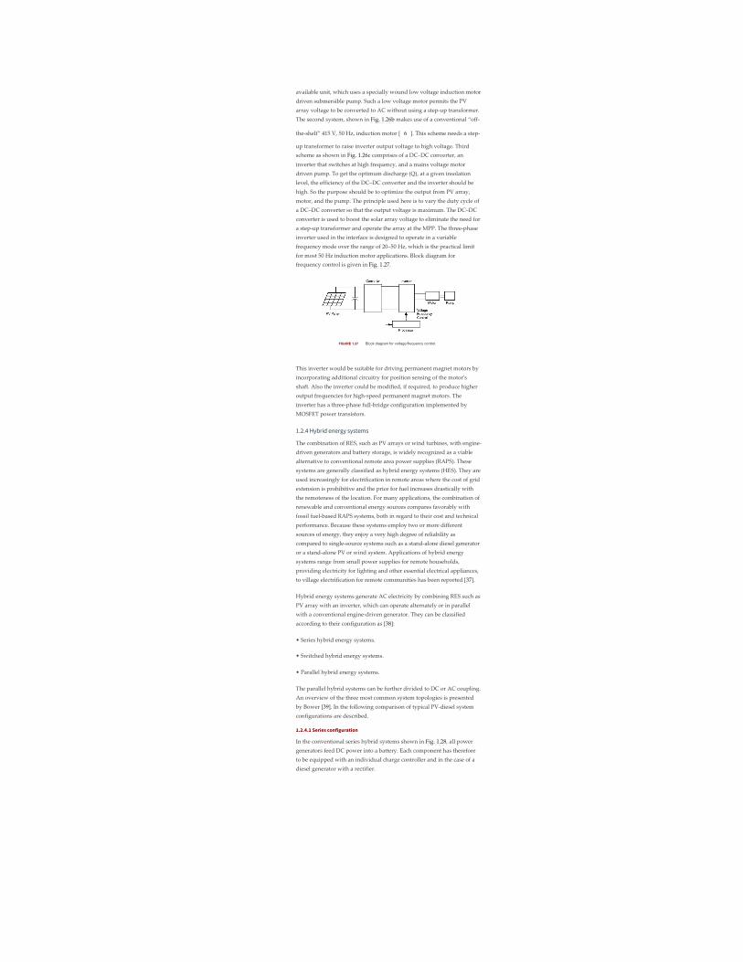
available unit, which uses a specially wound low voltage induction motordriven submersible pump. Such a low voltage motor permits the PVarray voltage to be converted to AC without using a step‑up transformer.The second system, shown in Fig. 1.26b makes use of a conventional “off‑
the‑shelf” 415 V, 50 Hz, induction motor [ 6 ]. This scheme needs a step‑
up transformer to raise inverter output voltage to high voltage. Thirdscheme as shown in Fig. 1.26c comprises of a DC–DC converter, aninverter that switches at high frequency, and a mains voltage motordriven pump. To get the optimum discharge (Q), at a given insolationlevel, the efficiency of the DC–DC converter and the inverter should behigh. So the purpose should be to optimize the output from PV array,motor, and the pump. The principle used here is to vary the duty cycle ofa DC–DC converter so that the output voltage is maximum. The DC–DCconverter is used to boost the solar array voltage to eliminate the need fora step‑up transformer and operate the array at the MPP. The three‑phaseinverter used in the interface is designed to operate in a variablefrequency mode over the range of 20–50 Hz, which is the practical limitfor most 50 Hz induction motor applications. Block diagram forfrequency control is given in Fig. 1.27.
FIGURE 1.27 Block diagram for voltage/frequency control.
This inverter would be suitable for driving permanent magnet motors byincorporating additional circuitry for position sensing of the motorʹsshaft. Also the inverter could be modified, if required, to produce higheroutput frequencies for high‑speed permanent magnet motors. Theinverter has a three‑phase full‑bridge configuration implemented byMOSFET power transistors.
1.2.4 Hybrid energy systems
The combination of RES, such as PV arrays or wind turbines, with engine‑driven generators and battery storage, is widely recognized as a viablealternative to conventional remote area power supplies (RAPS). Thesesystems are generally classified as hybrid energy systems (HES). They areused increasingly for electrification in remote areas where the cost of gridextension is prohibitive and the price for fuel increases drastically withthe remoteness of the location. For many applications, the combination ofrenewable and conventional energy sources compares favorably withfossil fuel‑based RAPS systems, both in regard to their cost and technicalperformance. Because these systems employ two or more differentsources of energy, they enjoy a very high degree of reliability ascompared to single‑source systems such as a stand‑alone diesel generatoror a stand‑alone PV or wind system. Applications of hybrid energysystems range from small power supplies for remote households,providing electricity for lighting and other essential electrical appliances,to village electrification for remote communities has been reported [37].
Hybrid energy systems generate AC electricity by combining RES such asPV array with an inverter, which can operate alternately or in parallelwith a conventional engine‑driven generator. They can be classifiedaccording to their configuration as [38]:
• Series hybrid energy systems.
• Switched hybrid energy systems.
• Parallel hybrid energy systems.
The parallel hybrid systems can be further divided to DC or AC coupling.An overview of the three most common system topologies is presentedby Bower [39]. In the following comparison of typical PV‑diesel systemconfigurations are described.
1.2.4.1 Series configuration
In the conventional series hybrid systems shown in Fig. 1.28, all powergenerators feed DC power into a battery. Each component has thereforeto be equipped with an individual charge controller and in the case of adiesel generator with a rectifier.

FIGURE 1.28 Series hybrid energy system.
To ensure reliable operation of series hybrid energy systems both thediesel generator and the inverter have to be sized to meet peak loads. Thisresults in a typical system operation where a large fraction of thegenerated energy is passed through the battery bank, therefore resultingin increased cycling of the battery bank and reduced system efficiency.AC power delivered to the load is converted from DC to regulated AC byan inverter or a motor generator unit. The power generated by the dieselgenerator is first rectified and subsequently converted back to AC beforebeing supplied to the load, which incurs significant conversion losses.
The actual load demand determines the amount of electrical powerdelivered by the PV array, wind generator, the battery bank, or the dieselgenerator. The solar and wind charger prevents overcharging of thebattery bank from the PV generator when the PV power exceeds the loaddemand and the batteries are fully charged. It may include MPPT toimprove the utilization of the available PV energy, although the energygain is marginal for a well‑sized system. The system can be operated inmanual or automatic mode, with the addition of appropriate batteryvoltage sensing and start/stop control of the engine‑driven generator.
Advantages:
• The engine‑driven generator can be sized to be optimally loaded whilesupplying the load and charging the battery bank, until a battery SOC of70–80% is reached.
• No switching of AC power between the different energy sources isrequired, which simplifies the electrical output interface.
• The power supplied to the load is not interrupted when the dieselgenerator is started.
• The inverter can generate a sine‑wave, modified square‑wave, orsquare‑wave depending on the application.
Disadvantages:
• The inverter cannot operate in parallel with the engine‑drivengenerator, therefore the inverter must be sized to supply the peak load ofthe system.
• The battery bank is cycled frequently, which shortens its lifetime.
• The cycling profile requires a large battery bank to limit the depth‑of‑discharge (DOD).
• The overall system efficiency is low, since the diesel cannot supplypower directly to the load.
• Inverter failure results in complete loss of power to the load, unless theload can be supplied directly from the diesel generator for emergencypurposes.
1.2.4.2 Switched configuration
Despite its operational limitations, the switched configuration remainsone of the most common installations in some developing countries. Itallows operation with either the engine‑driven generator or the inverteras the AC source, yet no parallel operation of the main generation sourcesis possible. The diesel generator and the RES can charge the battery bank.The main advantage compared with the series system is that the load canbe supplied directly by the engine‑driven generator, which results in ahigher overall conversion efficiency. Typically, the diesel generatorpower will exceed the load demand, with excess energy being used torecharge the battery bank. During periods of low electricity demand thediesel generator is switched off and the load is supplied from the PVarray together with stored energy. Switched hybrid energy systems canbe operated in manual mode, although the increased complexity of thesystem makes it highly desirable to include an automatic controller,which can be implemented with the addition of appropriate batteryvoltage sensing and start/stop control of the engine‑driven generator (Fig.1.29).

FIGURE 1.29 Switched PVdiesel hybrid energy system.
Advantages:
• The inverter can generate a sine‑wave, modified square‑wave, orsquare‑wave, depending on the particular application.
• The diesel generator can supply the load directly, therefore improvingthe system efficiency and reducing the fuel consumption.
Disadvantages:
• Power to the load is interrupted momentarily when the AC powersources are transferred.
• The engine‑driven alternator and inverter are typically designed tosupply the peak load, which reduces their efficiency at part loadoperation.
1.2.4.3 Parallel configuration
The parallel hybrid system can be further classified as DC and ACcouplings as shown in Fig. 1.30. In both schemes, a bi‑directional inverteris used to link between the battery and an AC source (typically the outputof a diesel generator). The bi‑directional inverter can charge the batterybank (rectifier operation) when excess energy is available from the dieselgenerator or by the renewable sources, as well as act as a DC–ACconverter (inverter operation). The bi‑directional inverter may alsoprovide “peak shaving” as part of a control strategy when the dieselengine is overloaded. In Fig. 1.30a, the renewable energy sources (RES)such as photovoltaic and wind are coupled on the DC side. DCintegration of RES results in “custom” system solutions for individualsupply cases requiring high costs for engineering, hardware, repair, andmaintenance. Furthermore, power system expandability for coveringneeds of growing energy and power demand is also difficult. A betterapproach would be to integrate the RES on the AC side rather than on theDC side as shown in Fig. 1.30b.
FIGURE 1.30 Parallel PVdiesel hybrid energy system: (a)DC decoupling and (b) AC coupling.
Parallel hybrid energy systems are characterized by two significantimprovements over the series and switched system configuration.
The inverter plus the diesel generator capacity rather than theirindividual component ratings limit the maximum load that can besupplied. Typically, this will lead to a doubling of the system capacity.The capability to synchronize the inverter with the diesel generatorallows greater flexibility to optimize the operation of the system. Futuresystems should be sized with a reduced peak capacity of the dieselgenerator, which results in a higher fraction of directly used energy andhence higher system efficiencies.
By using the same power electronic devices for both inverter and rectifieroperation, the number of system components is minimized. Additionally,wiring and system installation costs are reduced through the integration

of all power‑conditioning devices in one central power unit. This highlyintegrated system concept has advantages over a more modular approachto system design, but it may prevent convenient system upgrades whenthe load demand increases.
The parallel configuration offers a number of potential advantages overother system configurations. These objectives can only be met if theinteractive operation of the individual components is controlled by an“intelligent” hybrid energy management system. Although todayʹsgeneration of parallel systems include system controllers of varyingcomplexity and sophistication, they do not optimize the performance ofthe complete system. Typically, both the diesel generator and the inverterare sized to supply anticipated peak loads. As a result most parallelhybrid energy systems do not utilize their capability of parallel,synchronized operation of multiple power sources.
Advantages:
• The system load can be met in an optimal way.
• Diesel generator efficiency can be maximized.
• Diesel generator maintenance can be minimized.
• A reduction in the rated capacities of the diesel generator, battery bank,inverter, and renewable resources is feasible, while also meeting the peakloads.
Disadvantages:
• Automatic control is essential for the reliable operation of the system.
• The inverter has to be a true sine‑wave inverter with the ability tosynchronize with a secondary AC source.
• System operation is less transparent to the untrained user of the system.
1.2.4.4 Control of hybrid energy systems
The design process of hybrid energy systems requires the selection of themost suitable combination of energy sources, power‑conditioningdevices, and energy storage system together with the implementation ofan efficient energy dispatch strategy. System simulation software is anessential tool to analyze and compare possible system combinations. Theobjective of the control strategy is to achieve optimal operationalperformance at the system level. Inefficient operation of the dieselgenerator and “dumping” of excess energy is common for many RAPS,operating in the field. Component maintenance and replacementcontributes significantly to the lifecycle cost of systems. These aspects ofsystem operation are clearly related to the selected control strategy andhave to be considered in the system design phase.
Advanced system control strategies seek to reduce the number of cyclesand the DOD for the battery bank, run the diesel generator in its mostefficient operating range, maximize the utilization of the renewableresource, and ensure high reliability of the system. Due to the varyingnature of the load demand, the fluctuating power supplied by thephotovoltaic generator, and the resulting variation of battery SOC, thehybrid energy system controller has to respond to continuously changingoperating conditions. Figure 1.31 shows different operating modes for aPV single‑diesel system using a typical diesel dispatch strategy.
FIGURE 1.31 Operating modes for a PV singledieselhybrid energy system.
Mode (I): The base load, which is typically experienced at nighttime andduring the early morning hours, is supplied by energy stored in thebatteries. Photovoltaic power is not available and the diesel generator isnot started.
Mode (II): PV power is supplemented by stored energy to meet themedium load demand.
Mode (III): Excess energy is available from the PV generator, which isstored in the battery. The medium load demand is supplied from the PVgenerator.
Mode (IV): The diesel generator is started and operated at its nominalpower to meet the high evening load. Excess energy available from thediesel generator is used to recharge the batteries.
Mode (V): The diesel generator power is insufficient to meet the peak

load demand. Additional power is supplied from the batteries bysynchronizing the inverter AC output voltage with the alternatorwaveform.
Mode (VI): The diesel generator power exceeds the load demand, but it iskept operational until the batteries are recharged to a high SOC level.
In principle, most efficient operation is achieved if the generated power issupplied directly to the load from all energy sources, which also reducescycling of the battery bank. However, since diesel generator operation atlight loads is inherently inefficient, it is common practice to operate theengine‑driven generator at its nominal power rating and to recharge thebatteries from the excess energy. The selection of the most efficientcontrol strategy depends on fuel, maintenance and componentreplacement cost, the system configuration, environmental conditions, aswell as constraints imposed on the operation of the hybrid energy system.
1.2.5 Grid-connected PV systems
The utility interactive inverters not only conditions the power output ofthe PV arrays but ensures that the PV system output is fully synchronizedwith the utility power. These systems can be battery less or with batterybackup. Systems with battery storage (or flywheel) provide additionalpower supply reliability. The grid connection of PV systems is gatheringmomentum because of various rebate and incentive schemes. This systemallows the consumer to feed its own load utilizing the available solarenergy and the surplus energy can be injected into the grid under theenergy by back scheme to reduce the payback period. Grid‑connected PVsystems can become a part of the utility system. The contribution of solarpower depends upon the size of system and the load curve of the house.When the PV system is integrated with the utility grid, a two‑way powerflow is established. The utility grid will absorb excess PV power and willfeed the house during nighttime and at instants while the PV power isinadequate. The utility companies are encouraging this scheme in manyparts of the world. The grid‑connected system can be classified as:
• Rooftop application of grid‑connected PV system.
• Utility scale large system.
For small household PV applications, a roof mounted PV array can be thebest option. Solar cells provide an environmentally clean way ofproducing electricity, and rooftops have always been the ideal place toput them. With a PV array on the rooftop, the solar generated power cansupply residential load. The rooftop PV systems can help in reducing thepeak summer load to the benefit of utility companies by feeding thehousehold lighting, cooling, and other domestic loads. The batterystorage can further improve the reliability of the system at the time of lowinsolation level, nighttime, or cloudy days. But the battery storage hassome inherent problems like maintenance and higher cost.
For roof‑integrated applications, the solar arrays can be either mountedon the roof or directly integrated into the roof. If the roof integration doesnot allow for an air channel behind the PV modules for ventilationpurpose, then it can increase the cell temperature during the operationconsequently leading to some energy losses. The disadvantage with therooftop application is that the PV array orientation is dictated by the roof.In case, when the roof orientation differs from the optimal orientationrequired for the cells, then efficiency of the entire system would besuboptimal.
Utility interest in PV has centered on the large grid‑connected PVsystems. In Germany, USA, Spain, and in several other parts of the world,some large PV scale plants have been installed. The utilities are moreinclined with large scale, centralized power supply. The PV systems canbe centralized or distributed systems.
Grid‑connected PV systems must observe the islanding situation, whenthe utility supply fails. In case of islanding, the PV generators should bedisconnected from mains. PV generators can continue to meet only thelocal load, if the PV output matches the load. If the grid is re‑connectedduring islanding, transient overcurrents can flow through the PV systeminverters and the protective equipments like circuit breakers may bedamaged. The islanding control can be achieved through inverters or viathe distribution network. Inverter controls can be designed on the basis ofdetection of grid voltage, measurement of impedance, frequencyvariation, or increase in harmonics. Protection shall be designed for theislanding, short circuits, over/under‑voltages/currents, grounding, andlightening, etc.
The importance of the power generated by the PV system depends uponthe time of the day specially when the utility is experiencing the peakload. The PV plants are well suited to summer peaking but it dependsupon the climatic condition of the site. PV systems being investigated foruse as peaking stations would be competitive for load management. ThePV users can defer their load by adopting load management to get themaximum benefit out of the grid‑connected PV plants and feeding morepower into the grid at the time of peak load.

The assigned capacity credit is based on the statistical probability with
which the grid can meet peak demand [ 4 ]. The capacity factor during
the peaks is very similar to that of conventional plants and similarcapacity credit can be given for the PV generation except at the timeswhen the PV plants are generating very less power unless adequatestorage is provided. With the installation of PV plants, the need of extratransmission lines, transformers can be delayed or avoided. Thedistributed PV plants can also contribute in providing reactive powersupport to the grid and reduce burden on VAR compensators.
1.2.5.1 Inverters for grid-connected applications
Power conditioner is the key link between the PV array and mains in thegrid‑connected PV system. It acts as an interface that converts DC currentproduced by the solar cells into utility grade AC current. The PV systembehavior relies heavily on the power‑conditioning unit. The invertersshall produce good quality sine‑wave output. The inverter must followthe frequency and voltage of the grid and the inverter has to extractmaximum power from the solar cells with the help of MPPT and theinverter input stage varies the input voltage until the MPP on the I–Vcurve is found. The inverter shall monitor all the phases of the grid. Theinverter output shall be controlled in terms of voltage and frequencyvariation. A typical grid‑connected inverter may use a PWM scheme andoperates in the range of 2–20 kHz.
1.2.5.2 Inverter classifications
The inverters used for the grid interfacing are broadly classified as:
• Voltage source inverters (VSI).
• Current source inverters (CSI).
Whereas the inverters based on the control schemes can be classified as:
• Current controlled (CC).
• Voltage controlled (VC).
The source is not necessarily characterized by the energy source for thesystem. It is a characteristic of the topology of the inverter. It is possible tochange from one source type to another source type by the addition ofpassive components. In the voltage source inverter (VSI), the DC side ismade to appear to the inverter as a voltage source. The VSIs have acapacitor in parallel across the input whereas the CSIs have an inductor isseries with the DC input. In the CSI, the DC source appears as a currentsource to the inverter. Solar arrays are fairly good approximation to acurrent source. Most PV inverters are voltage source even though the PVis a current source. Current source inverters are generally used for largemotor drives though there have been some PV inverters built using acurrent source topology. The VSI is more popular with the PWM VSIdominating the sine‑wave inverter topologies.
Figure 1.32a shows a single‑phase full‑bridge bi‑directional VSI with (a)voltage control and phase‑shift (δ) control – voltage‑controlled voltagesource inverter (VCVSI). The active power transfer from the PV panels isaccomplished by controlling the phase angle δ between the convertervoltage and the grid voltage. The converter voltage follows the gridvoltage. Figure 1.32b shows the same VSI operated as a current controlled(CCVSI). The objective of this scheme is to control active and reactivecomponents of the current fed into the grid using PWM techniques.
FIGURE 1.32 Voltage source inverter: (a) voltage controland (b) current control.
1.2.5.3 Inverter types
Different types are being in use for the grid‑connected PV applicationssuch as:

• Line‑commutated inverter.
• Self‑commutated inverter.
• Inverter with high‑frequency transformer.
1.2.5.3.1 Line-commutated inverter
The line‑commutated inverters are generally used for the electric motorapplications. The power stage is equipped with thyristors. The maximumpower tracking control is required in the control algorithm for solarapplication. The basic diagram for a single‑phase line‑commutated
inverter is shown in the Fig. 1.33 [ 3 ].
FIGURE 1.33 Linecommuted singlephase inverter.
The driver circuit has to be changed to shift the firing angle from therectifier operation (0 < ɸ < 90) to inverter operation (90 < ɸ < 180). Six‑pulse or 12‑pulse inverter are used for the grid interfacing but 12‑pulseinverters produce less harmonics. The thyristor type inverters require alow impedance grid interface connection for commutation purpose. If themaximum power available from the grid connection is less than twice therated PV inverter power, then the line‑commutated inverter should not
be used [ 3 ]. The line‑commutated inverters are cheaper but inhibits
poor power quality. The harmonics injected into the grid can be largeunless taken care of by employing adequate filters. These line‑commutated inverters also have poor power factor, poor power quality,and need additional control to improve the power factor. Transformercan be used to provide the electrical isolation. To suppress the harmonicsgenerated by these inverters, tuned filters are employed and reactivepower compensation is required to improve the lagging power factor.
1.2.5.3.2 Self-commutated inverter
A switch mode inverter using pulse width modulated (PWM) switchingcontrol, can be used for the grid connection of PV systems. The basicblock diagram for this type of inverter is shown in the Fig. 1.34. Theinverter bridges may consist of bipolar transistors, MOSFET transistors,IGBTʹs, or gate turn‑off thyristorʹs (GTOʹs), depending upon the type ofapplication. GTOʹs are used for the higher power applications, whereasIGBTʹs can be switched at higher frequencies i.e. 16 kHz, and aregenerally used for many grid‑connected PV applications. Most of thepresent day inverters are self‑commutated sine‑wave inverters.
FIGURE 1.34 Selfcommutated inverter with PWMswitching.
Based on the switching control, the voltage source inverters can befurther classified based on the switching control as:
• PWM (pulse width modulated) inverters.
• Square‑wave inverters.
• Single‑phase inverters with voltage cancellations.
• Programmed harmonic elimination switching.
• Current controlled modulation.
1.2.5.3.3 Inverter with high-frequency transformer
The 50 Hz transformer for a standard PV inverter with PWM switchingscheme can be very heavy and costly. While using frequencies more than
20 kHz, a ferrite core transformer can be a better option [ 3 ]. A circuit
diagram of a grid‑connected PV system using high frequency transformeris shown in the Fig. 1.35.
FIGURE 1.35 PV inverter with high frequency transformer.

The capacitor on the input side of high frequency inverter acts as thefilter. The high frequency inverter with PWM is used to produce a highfrequency AC across the primary winding of the high frequencytransformer. The secondary voltage of this transformer is rectified usinghigh frequency rectifier. The DC voltage is interfaced with a thyristorinverter through low‑pass inductor filter and hence connected to the grid.The line current is required to be sinusoidal and in phase with the linevoltage. To achieve this, the line voltage (V ) is measured to establish thereference waveform for the line current I* . This reference current I*multiplied by the transformer ratio gives the reference current at theoutput of high frequency inverter. The inverter output can be controlledusing current control technique [40]. These inverters can be with lowfrequency transformer isolation or high frequency transformer isolation.The low frequency (50/60 Hz) transformer of a standard inverter withPWM is a very heavy and bulky component. For residential gridinteractive rooftop inverters below 3 kW rating, high frequencytransformer isolation is often preferred.
1.2.5.3.4 Other PV inverter topologies
In this section, some of the inverter topologies discussed in variousresearch papers have been discussed.
A. Multilevel converters
Multilevel converters can be used with large PV systems where multiplePV panels can be configured to create voltage steps. These multilevelvoltage‑source converters can synthesize the AC output terminal voltagefrom different level of DC voltages and can produce staircase waveforms.This scheme involves less complexity, and needs less filtering. One of theschemes (half‑bridge diode‑clamped three level inverter [41]) is given inFig. 1.36. There is no transformer in this topology. Multilevel converterscan be beneficial for large systems in terms of cost and efficiency.Problems associated with shading and malfunction of PV units need to beaddressed.
FIGURE 1.36 Halfbridge diodeclamped threelevelinverter.
B. Non-insulated voltage source
In this scheme [42], string of low voltage PV panels or one high‑voltageunit can be coupled with the grid through DC to DC converter andvoltage‑source inverter. This topology is shown in Fig. 1.37. PWM‑switching scheme can be used to generate AC output. Filter has beenused to reject the switching components.
FIGURE 1.37 Noninsulated voltage source.
C. Non-insulated current source
This type of configuration is shown in Fig. 1.38. Non‑insulated current‑source inverters [42] can be used to interface the PV panels with the grid.This topology involves low cost which can provide better efficiency.Appropriate controller can be used to reduce current harmonics.
FIGURE 1.38 Noninsulated current source.
D. Buck converter with half-bridge transformer link
PV panels are connected to grid via buck converter and half bridge asshown in Fig. 1.39. In this, high‑frequency PWM switching has been usedat the low‑voltage PV side to generate an attenuated rectified 100 Hz sine‑
1
L L

wave current waveform [43]. Half‑wave bridge is utilized to convert thisoutput to 50 Hz signal suitable for grid interconnection. To step up thevoltage, transformer has also been connected before the grid connectionpoint.
FIGURE 1.39 Buck converter with halfbridge transformerlink.
E. Flyback converter
This converter topology steps up the PV voltage to DC bus voltage. Pulsewidth modulation operated converter has been used for grid connectionof PV system (Fig. 1.40). This scheme is less complex and has less numberof switches. Flyback converters can be beneficial for remote areas due toless complex power conditioning components.
FIGURE 1.40 Flyback converter.
F. Interface using paralleled PV panels
Low voltage AC bus scheme [44] can be comparatively efficient andcheaper option. One of the schemes is shown in Fig. 1.41. A number ofsmaller PV units can be paralleled together and then connected tocombine single low‑frequency transformer. In this scheme, the PV panelsare connected in parallel rather than series to avoid problems associatedwith shading or malfunction of one of the panels in series connection.
FIGURE 1.41 Converter using parallel PV units.
1.2.5.4 Power control through PV inverters
The system shown in Fig. 1.42 shows control of power flow on to the grid[45]. This control can be an analog or a microprocessor system. Thiscontrol system generates the waveforms and regulates the waveformamplitude and phase to control the power flow between the inverter andthe grid. The grid‑interfaced PV inverters, voltage‑controlled VSI(VCVSI), or current‑controlled VSI (CCVSI) have the potential of bi‑directional power flow. They cannot only feed the local load but also canexport the excess active and reactive power to the utility grid. Anappropriate controller is required in order to avoid any error in powerexport due to errors in synchronization, which can overload the inverter.
FIGURE 1.42 Schematic diagram of a parallel processingDGS.
There are advantages and limitations associated with each controlmechanism. For instance, VCVSIs provide voltage support to the load(here the VSI operates as a voltage source), while CCVSIs provide currentsupport (here the VSI operates as a current source). The CCVSI is faster inresponse compared to the VCVSI, as its power flow is controlled by theswitching instant, whereas in the VCVSI the power flow is controlled byadjusting the voltage across the decoupling inductor. Active and reactivepower are controlled independently in the CCVSI, but are coupled in theVCVSI. Generally, the advantages of one type of VSI are considered as alimitation of the other type [46].
Figure 1.43 shows the simplified/equivalent schematic diagram of aVCVSI. For the following analysis it is assumed that the output low‑passfilters (L and C ) of VSIs will filter out high‑order harmonics generated byPWMs. The decoupling inductor (X ) is an essential part of any VCVSI asit makes the power flow control possible. In a VCVSI, the power flow ofthe distributed generation system (DGS) is controlled by adjusting theamplitude and phase (power angle (δ)) of the inverter output voltage
f f
m

(1.7)
(1.8)
(1.9)
(1.10)
with respect to the grid voltage. Hence, it is important to consider theproper sizing of the decoupling inductor and the maximum power angleto provide the required power flow when designing VCVSIs. The phasordiagram of a simple grid‑inverter interface with a first‑order filter areshown in Fig. 1.44.
FIGURE 1.43 The equivalent circuit diagram of a VCVSI.
FIGURE 1.44 Phasor diagram of a VCVSI with resistiveload and assuming the grid is responsible for supplying theactive power [46].
Referring to Fig. 1.43, the fundamental grid current (I ) can be expressedby Eq. (1.7):
where V and V are respectively the grid and the VCVSIʹs fundamentalvoltages, and X is the decoupling inductor impedance. Using per unitvalues (S = V /Z , V = V , and Z = X ) where V , Z , and Sare the base voltage, impedance and complex power values respectively.The grid apparent power can be expressed as Eq. (1.8).
Using per unit values, the complex power of the VCVSI and decouplinginductor are
where S , S , and S are per unit values of the grid, VCVSI, anddecoupling inductor apparent power respectively, and V is the per unitvalue of the grid voltage.
Figure 1.45 shows the equivalent schematic diagram of a CCVSI. As aCCVSI controls the current flow using the VSI switching instants, it canbe modeled as a current source and there is no need for a decouplinginductor (Fig. 1.45). As the current generated from the CCVSI can becontrolled independently from the AC voltage, the active and reactivepower controls are decoupled. Hence, unity power factor operation ispossible for the whole range of the load. This is one of the mainadvantages of CCVSIs.
FIGURE 1.45 The equivalent circuit of a CCVSI.
As the CCVSI is connected in parallel to the DGS, it follows the gridvoltage. Figure 1.46 shows the phasor diagram of a CCVSI based DGS in
g
g c
m
base base base base c base m base base base
gpu cpu xpu
gpu
2

(1.12)
(1.11)
(1.13)
the presence of an inductive load (considering the same assumption asVCVSI section). Figure 1.49 shows that when the grid voltage increases,the loadʹs active power consumption, which supplied by the gridincreases and the CCVSI compensates the increase in the load reactivepower demand. In this case, the CCVSI maintains grid supply at unitypower factor, keeping the current phase delay with respect to the gridvoltage at a fixed value (θ). Therefore, the CCVSI cannot maintain theload voltage in the presence of a DGS without utilizing extra hardwareand control mechanisms. This limitation on load voltage stabilization isone of the main drawbacks of CCVSI based DGS.
FIGURE 1.46 Phasor diagram of a CCVSI with inductiveload and assuming grid is responsible for supplying the activepower [46].
Assuming the load active current demand is supplied by the grid(reactive power support function), the required grid current can berewritten as follows
where, S is the demanded load apparent power. Forgrid power conditioning, it is preferred that the load operate at unitypower factor. Therefore, the CCVSI must provide the remainder of therequired current Eq. (1.12)
For demand side management (DSM), it is desirable to supply the activepower by the RES, where excess energy from the RES is injected into theDGS. The remaining load reactive power will be supplied by the CCVSI.Hence Eq. (1.12) can be rewritten as Eq. (1.13).
When using a voltage controller for grid‑connected PV inverter, it hasbeen observed that a slight error in the phase of synchronizing waveformcan grossly overload the inverter whereas a current controller is muchless susceptible to voltage phase shifts [45]. Due to this reason, the currentcontrollers are better suited for the control of power export from the PVinverters to the utility grid since they are less sensitive to errors insynchronizing sinusoidal voltage waveforms.
A prototype current‑controlled type power conditioning system has beendeveloped by the first author and tested on a weak rural feeder line atKalbarri in Western Australia [47]. The choice may be between additionalconventional generating capacity at a centralized location or addingsmaller distributed generating capacities using RES like PV. The latteroption can have a number of advantages like:
• The additional capacity is added wherever it is required withoutadding additional power distribution infrastructure. This is a criticalconsideration where the power lines and transformers are already at orclose to their maximum ratings.
• The power conditioning system can be designed to provide much morethan just a source of real power, for minimal extra cost. A converterproviding real power needs only a slight increase in ratings to handlesignificant amounts of reactive or even harmonic power. The sameconverter that converts DC PV power to AC power can simultaneouslyprovide the reactive power support to the week utility grid.
The block diagram of the power conditioning system used in the Kalbarriproject has been shown in the Fig. 1.47. This CCVSI operates with arelatively narrow switching frequency band near 10 kHz. The controldiagram indicates the basic operation of the power conditioning system.The two outer control loops operate to independently control the real and
L

reactive power flow from the PV inverter. The real power is controlled byan outer MPPT algorithm with an inner DC link voltage control loopproviding the real current magnitude request I* and hence the realpower export through PV converter is controlled through the DC linkvoltage regulation. The DC link voltage is maintained at a reference valueby a PI control loop, which gives the real current reference magnitude asitʹs output. At regular intervals, the DC link voltage is scanned over theentire voltage range to check that the algorithm is operating on theabsolute MPP and is not stuck around a local MPP. During the night, theconverter can still be used to regulate reactive power of the grid‑connected system although it cannot provide active power. During thistime, the PI controller maintain a minimum DC link voltage to allow thepower conditioning system to continue to operate, providing thenecessary reactive power.
FIGURE 1.47 Block diagram of Kalbarri power conditioningsystem.
The AC line voltage regulation is provided by a separate reactive powercontrol, which provides the reactive current magnitude reference I* . Thecontrol system has a simple transfer function, which varies the reactivepower command in response to the AC voltage fluctuations. Common tothe outer real and reactive power control loops is an inner higherbandwidth zero average current error (ZACE) current control loop. I* isin phase with the line voltages, and I* is at 90° to the line voltage. Theseare added together to give one (per phase) sinusoidal converter currentreference waveform (I* ). The CCVSI control consists of analog anddigital circuitry which acts as a ZACE transconductance amplifier inconverting I* into AC power currents [48].
1.2.5.5 System configurations
The utility compatible inverters are used for power conditioning andsynchronization of PV output with the utility power. In general, fourtypes of battery‑less grid‑connected PV system configurations have beenidentified:
• Central plant inverter.
• Multiple string DC/DC converter with single output inverter.
• Multiple string inverter.
• Module integrated inverter.
1.2.5.5.1 Central plant inverter
In the central plant inverter, usually a large inverter is used to convert DCpower output of PV arrays to AC power. In this system, the PV modulesare serially stringed to form a panel (or string) and several such panelsare connected in parallel to a single DC bus. The block diagram of such ascheme is shown in Fig. 1.48.
FIGURE 1.48 Central plant inverter.
1.2.5.5.2 Multiple string DC/DC converter
In multiple string DC/DC converter, as shown in Fig. 1.49, each string willhave a boost DC/DC converter with transformer isolation. There will be acommon DC link, which feeds a transformer‑less inverter.
FIGURE 1.49 Multiple string DC/DC converter.
1.2.5.5.3 Multiple string inverters
Figure 1.50 shows the block diagram of multiple string inverter system. Inthis scheme, several modules are connected in series on the DC side toform a string. The output from each string is converted to AC through asmaller individual inverter. Many such inverters are connected in parallelon the AC side. This arrangement is not badly affected by the shading of
p
Q
p
Q
ac
ac

the panels. It is also not seriously affected by inverter failure.
FIGURE 1.50 Multiple string inverter.
1.2.5.5.4 Module integrated inverter
In the module integrated inverter system (Fig. 1.51), each module(typically 50–300 W) will have a small inverter. No cabling is required. Itis expected that high volume of small inverters will bring down the cost.
FIGURE 1.51 Module integrated inverter.
1.2.5.6 Grid-compatible inverters characteristics
The characteristics of the grid‑compatible inverters are:
• Response time.
• Power factor.
• Frequency control.
• Harmonic output.
• Synchronization.
• Fault current contribution.
• DC current injection.
• Protection.
The response time of the inverters shall be extremely fast and governedby the bandwidth of the control system. Absence of rotating mass and useof semiconductor switches allow inverters to respond in millisecond timeframe. The power factor of the inverters is traditionally poor due todisplacement power factor and the harmonics. But with the latestdevelopment in the inverter technology, it is possible to maintain thepower factor close to unity. The converters/inverters have the capabilityof creating large voltage fluctuation by drawing reactive power from theutility rather than supplying [49]. With proper control, inverters canprovide voltage support by importing/exporting reactive power topush/pull towards a desired set point. This function would be of moreuse to the utilities as it can assist in the regulation of the grid system atthe domestic consumer level.
Frequency of the inverter output waveshape is locked to the grid.Frequency bias is where the inverter frequency is deliberately made torun at 53 Hz. When the grid is present, this will be pulled down to thenominal 50 Hz. If the grid fails, it will drift upwards towards 53 Hz andtrip on over frequency. This can help in preventing islanding.
Harmonics output from the inverters have been very poor traditionally.Old thyristor‑based inverters are operated with slow switching speedsand could not be pulse width modulated. This resulted in invertersknown as six‑pulse or twelve‑pulse inverters. The harmonics so producedfrom the inverters can be injected into the grid, resulting in losses, heatingof appliances, tripping of protection equipments, and poor power quality.The number of pulses being the number of steps in a sine‑wave cycle.With the present advent in the power electronics technology, the invertercontrols can be made very good. Pulse width modulated invertersproduce high quality sine waves. The harmonic levels are very low, andcan be lower than the common domestic appliances. If the harmonics arepresent in the grid voltage waveform, harmonic currents can be inducedin the inverter. These harmonic currents, particularly those generated bya voltage‑controlled inverter, will in fact help in supporting the grid.These are good harmonic currents. This is the reason that the harmoniccurrent output of inverters must be measured onto a clean grid source sothat the only harmonics being produced by the inverters are measured.
Synchronization of inverter with the grid is performed automatically andtypically uses zero crossing detection on the voltage waveform. An

inverter has no rotating mass and hence has no inertia. Synchronizationdoes not involve the acceleration of a rotating machine. Consequently thereference waveforms in the inverter can be jumped to any point requiredwithin a sampling period. If phase‑locked loops are used, it could take upa few seconds. Phase‑locked loops are used to increase the immunity tonoise. This allows the synchronization to be based on several cycles ofzero crossing information. The response time for this type of locking willbe slower.
Photovoltaic panels produce a current that is proportional to the amountof light falling on them. The panels are normally rated to produce1000 W/m at 25° C. Under these conditions, the short‑circuit currentpossible from these panels is typically only 20% higher than the nominalcurrent whereas it is extremely variable for wind. If the solar radiation islow then the maximum current possible under short‑circuit is going to beless than the nominal full load current. Consequently PV systems cannotprovide the short‑circuit capacity to the grid. If a battery is present, thefault current contribution is limited by the inverter. With the batterystorage, it is possible for the battery to provide the energy. However,inverters are typically limited between 100 and 200% of nominal ratingunder current limit conditions. The inverter needs to protect itself againstthe short circuits because the power electronic components will typicallybe destroyed before a protection device like circuit breaker trips.
In case of inverter malfunction, inverters have the capability to inject theDC components into the grid. Most utilities have guidelines for thispurpose. A transformer shall be installed at the point of connection on theAC side to prevent DC from being entering into the utility network. Thetransformer can be omitted when a DC detection device is installed at thepoint of connection on the AC side in the inverter. The DC injection isessentially caused by the reference or power electronics device producinga positive half cycle that is different from the negative half cycle resultingin the DC component in the output. If the DC component can bemeasured, it can then be added into the feedback path to eliminate theDC quantity.
1.2.5.6.1 Protection requirements
A minimum requirement to facilitate the prevention of islanding is thatthe inverter energy system protection operates and isolates the inverterenergy system from the grid if:
• Over voltage.
• Under voltage.
• Over frequency.
• Under frequency exists.
These limits may be either factory set or site programmable. Theprotection voltage operating points may be set in a narrower band ifrequired, e.g. 220–260 V. In addition to the passive protection detailedabove, and to prevent the situation where islanding may occur becausemultiple inverters provide a frequency reference for one another,inverters must have an accepted active method of islanding preventionfollowing grid failure, e.g. frequency drift, impedance measurement, etc.Inverter controls for islanding can be designed on the basis of detection ofgrid voltage, measurement of impedance, frequency variation, or increasein harmonics. This function must operate to force the inverter outputoutside the protection tolerances specified previously, thereby resultingin isolation of the inverter energy system from the grid. The maximumcombined operation time of both passive and active protections should be2 s after grid failure under all local load conditions. If frequency shift isused, it is recommended that the direction of shift be down. The inverterenergy system must remain disconnected from the grid until thereconnection conditions are met. Some inverters produce high voltagespikes, especially at light load, which can be dangerous for the electronicequipment. IEEE P929 gives some idea about the permitted voltage limits.
If the inverter energy system does not have the above frequency features,the inverter must incorporate an alternate anti‑islanding protectionfeature that is acceptable to the relevant electricity distributor. If theprotection function above is to be incorporated in the inverter it must betype tested for compliance with these requirements and accepted by therelevant electricity distributor. Otherwise other forms of externalprotection relaying are required which have been type tested forcompliance with these requirements and approved by the relevantelectricity distributor. The inverter shall have adequate protection againstshort circuit, other faults, and overheating of inverter components.
1.3 Power electronics for wind power systems
In rural USA, the first wind mill was commissioned in 1890 to generateelectricity. Today, large wind generators are competing with utilities insupplying clean power economically. The average wind turbine size hasbeen 300–600 kW until recently. The new wind generators of 1–3 MWhave been developed and are being installed worldwide, and prototypeof even higher capacity is under development. Improved wind turbine
2

(1.14)
designs and plant utilization have resulted in significant reduction inwind energy generation cost from 35 cents per kWh in 1980 to less than5 cents per kWh in 1999, in locations where wind regime is favorable. Atthis generation cost, wind energy has become one of the least cost powersources. Main factors that have contributed to the wind power technologydevelopment are:
• High strength fiber composites for manufacturing large low‑costblades.
• Variable speed operation of wind generators to capture maximumenergy.
• Advancement in power electronics and associated cost.
• Improved plant operation and efficiency.
• Economy of scale due to availability of large wind generation plants.
• Accumulated field experience improving the capacity factor.
• Computer prototyping by accurate system modeling and simulation.
The Table 1.2 is for wind sites with average annual wind speed of 7m/s at30 m hub height. Since 1980s, wind technology capital costs have reducedby 80% worldwide. Operation and maintenance costs have declined by80% and the availability factor of grid‑connected wind plants hasincreased to 95%. At present, the capital cost of wind generator plants hasdropped to about $600 per kW and the electricity generation cost hasreduced to 6 cents per kWh. It is expected to reduce the generation costbelow 4 cents per kWh. Keeping this in view, the wind generation isgoing to be highly competitive with the conventional power plants. InEurope, USA, and Asia the wind power generation is increasing rapidlyand this trend is going to continue due to economic viability of windpower generation.
Table 1.2
Wind Power Technology Developments
1980 1999 Future
Cost per kWh $0.35–0.40 $0.05–0.07 <$0.04
Capital cost per kW $2000–3000 $500–700 <$400
Operating life 5–7 Years 20 Years 30 Years
Capacity factor (average) 15% 25–30% >30%
Availability 50–65% 95% >95%
Wind turbine unit sizerange
50–150 kW 300–1000 kW 500–2000 kW
The technical advancement in power electronics is playing an importantpart in the development of wind power technology. The contribution ofpower electronics in control of fixed speed/variable speed wind turbinesand interfacing to the grid is of extreme importance. Because of thefluctuating nature of wind speed, the power quality and reliability of thewind based power system needs to be evaluated in detail. Appropriatecontrol schemes require power conditioning.
1.3.1 Basics of wind power
The ability of a wind turbine to extract power from wind is a function ofthree main factors:
• Wind power availability.
• Power curve of the machine.
• Ability of the machine to respond to wind perturbations.
The mechanical power produced by a wind turbine is given by
The power from the wind is a cubic function of windspeed. The curve for power coefficient C and λ is required to infer thevalue of C for λ based on wind speed at that time.
Where tip speed ratio, , ρ = Air density, Kg m , C =power coefficient, A = wind turbine rotor swept area, m , U = wind speedin m/s.
The case of a variable speed wind turbine with a pitch mechanism that
p
p
p−3
2

(1.15)
(1.16)
alters the effective rotor dynamic efficiency, can be easily considered if anappropriate expression for C as a function of the pitch angle is applied.The power curve of a typical wind turbine is given in Fig. 1.52 as afunction of wind speed.
FIGURE 1.52 Power curve of wind turbine as a function ofwind speed [50].
The C –λ curve for 150 kW windmaster machine is given in Fig. 1.53,which has been inferred from the power curve of the machine. The ratioof shaft power to the available power in the wind is the efficiency ofconversion, known as the power coefficient C
FIGURE 1.53 C –λ curve of wind machine [50].
The power coefficient is a function of turbine blade tip speed to windspeed ratio (β). A tip speed ratio of 1 means the blade tips are moving atthe same speed as the wind and when β is 2 the tips are moving at twicethe speed of the wind and so on [51]. Solidity (σ) is defined as the ratio ofthe sum of the width of all the blades to the circumference of the rotor.Hence,
where N = number of blades and d = width of the blades.
The power from a wind turbine doubles as the area swept by the bladesdoubles. But doubling of the wind speed increases the power outputeight times. Figure 1.54 gives a family of power curves for a wind turbine.If the loading of the turbine is controlled such that the operating point isalong the maximum power locus at different wind speeds, then the windenergy system will be more efficient.
FIGURE 1.54 Turbine power vs shaft speed curves.
1.3.1.1 Types of wind turbines
There are two types of wind turbines available Fig. 1.55:
p
p
p
p

FIGURE 1.55 Typical diagram of HAWTs and VAWTs.
• Horizontal axis wind turbines (HAWTs).
• Vertical axis wind turbines (VAWTs).
Vertical axis wind turbines (VAWTs) have an axis of rotation that isvertical, and so, unlike the horizontal wind turbines, they can capturewinds from any direction without the need to reposition the rotor whenthe wind direction changes (without a special yaw mechanism). Verticalaxis wind turbines were also used in some applications as they have theadvantage that they do not depend on the direction of the wind. It ispossible to extract power relatively easier. But there are somedisadvantages such as no self starting system, smaller power coefficientthan obtained in the horizontal axis wind turbines, strong discontinuationof rotations due to periodic changes in the lift force, and the regulation ofpower is not yet satisfactory.
The horizontal axis wind turbines are generally used. Horizontal axiswind turbines are, by far, the most common design. There are a largenumber of designs commercially available ranging from 50 W to 4.5 MW.The number of blades ranges from one to many in the familiar agriculturewindmill. The best compromise for electricity generation, where highrotational speed allows use of a smaller and cheaper electric generator, istwo or three blades. The mechanical and aerodynamic balance is betterfor three bladed rotor. In small wind turbines, three blades are common.Multiblade wind turbines are used for water pumping on farms.
Based on the pitch control mechanisms, the wind turbines can also beclassified as:
• Fixed pitch wind turbines.
• Variable pitch wind turbines.
Different manufacturers offer fixed pitch and variable pitch blades.Variable pitch is desirable on large machines because the aerodynamicloads on the blades can be reduced and when used in fixed speedoperation they can extract more energy. But necessary mechanismsrequire maintenance and for small machines, installed in remote areas,fixed pitch seems more desirable and economical. In some machines,power output regulation involves yawing blades so that they no longerpoint into the wind. One such system designed in Western Australia hasa tail that progressively tilts the blades in a vertical plane so that theypresent a small surface to the wind at high speeds.
The active power of a wind turbine can be regulated by either designingthe blades to go into an aerodynamic stall beyond the designated windspeed, or by feathering the blades out of the wind, which results inreducing excess power using a mechanical and electrical mechanism.Recently, an active stall has been used to improve the stability of windfarms. This stall mechanism can prevent power deviation from gustywinds to pass through the drive train [52].
Horizontal axis wind turbines can be further classified into fixed speed(FS) or variable speed (VS). The FS wind turbine generator (FSWT) isdesigned to operate at maximum efficiency while operating at a ratedwind speed. In this case, the optimum tip‑speed ratio is obtained for therotor airfoil at a rated wind speed. For a VS wind turbine generator(VSWT), it is possible to obtain optimum wind speed at different windspeeds. Hence this enables the VS wind turbine to increase its energycapture. The general advantages of a VSWT are summarized as follows:
• VSWTs are more efficient than the FSWTs.
• At low wind speeds the wind turbines can still capture the maximumavailable power at the rotor, hence increasing the possibility of providingthe rated power for wide speed range.
1.3.1.2 Types of wind generators
Schemes based on permanent magnet synchronous generators (PMSG)and induction generators are receiving close attention in wind powerapplications because of their qualities such as ruggedness, low cost,manufacturing simplicity, and low maintenance requirements. Despitemany positive features over the conventional synchronous generators, thePMSG was not being used widely [23]. However, with the recent adventin power electronics, it is now possible to control the variable voltage,

variable frequency output of PMSG. The permanent magnet machine isgenerally favored for developing new designs, because of higherefficiency and the possibility of a rather smaller diameter. These PMSGmachines are now being used with variable‑speed wind machines.
In large power system networks, synchronous generators are generallyused with fixed‑speed wind turbines. The synchronous generators cansupply the active and reactive power both, and their reactive power flowcan be controlled. The synchronous generators can operate at any powerfactor. For the induction generator, driven by a wind turbine, it is a well‑known fact that it can deliver only active power, while consumingreactive power
Synchronous generators with high power rating are significantly moreexpensive than induction generators of similar size. Moreover, directconnected synchronous generators have the limitation of rotational speedbeing fixed by the grid frequency. Hence, fluctuation in the rotor speeddue to wind gusts lead to higher torque in high power outputfluctuations and the derived train. Therefore in grid‑connectedapplication, synchronous generators are interfaced via power convertersto the grid. This also allows the synchronous generators to operate windturbines in VS, which makes gear‑less operation of the VSWT possible.
The squirrel‑cage induction generators are widely used with the fixed‑speed wind turbines. In some applications, wound rotor inductiongenerators have also been used with adequate control scheme forregulating speed by external rotor resistance. This allows the shape of thetorque‑slip curve to be controlled to improve the dynamics of the drivetrain. In case of PMSG, the converter/inverter can be used to control thevariable voltage, variable frequency signal of the wind generator atvarying wind speed. The converter converts this varying signal to the DCsignal and the output of converter is converted to AC signal of desiredamplitude and frequency.
The induction generators are not locked to the frequency of the network.The cyclic torque fluctuations at the wind turbine can be absorbed byvery small change in the slip speed. In case of the capacitor excitedinduction generators, they obtain the magnetizing current fromcapacitors connected across its output terminals [51, 53, 54].
To take advantage of VSWTs, it is necessary to decouple the rotor speedand the grid frequency. There are different approaches to operate theVSWT within a certain operational range (cut‑in and cut‑out wind speed).One of the approaches is dynamic slip control, where the slip is allowedto vary upto 10% [55]. In these cases, doubly‑fed induction generators(DFIG) are used (Fig. 1.56). One limitation is that DFIG require reactivepower to operate. As it is not desired that the grid supply this reactivepower, these generators are usually equipped with capacitors. A gear boxforms an essential component of the wind turbine generator (WTG) usinginduction generators. This results in the following limitations:
FIGURE 1.56 Variable speed doublyfed inductiongenerator (VSDFIG) system.
• Frequent maintenance.
• Additional cost.
• Additional losses.
With the emergence of large wind power generation, increased attentionis being directed towards wound rotor induction generators (WRIG)controlled from the rotor side for variable speed constant frequency(VSCF) applications. A wound rotor induction generator has a rotorcontaining a 3‑phase winding. These windings are made accessible to theoutside via slip rings. The main advantages of a wound rotor inductiongenerator for VSCF applications are:
• Easier generator torque control using rotor current control.
• Smaller generator capacity as the generated power can be accessedfrom the stator as well as from the rotor. Usually the rotor power isproportional to the slip speed (shaft speed–synchronous speed).Consequently smaller rotor power converters are required. The frequencyconverter in the rotor (inverter) directly controls the current in the rotorwinding, which enables the control of the whole generator output. Thepower electronic converters generally used are rated at 20–30% of thenominal generator power.
• Fewer harmonics exist because control is in the rotor while the stator is

directly connected to the grid.
If the rotor is short‑circuited (making it the equivalent of a cage rotorinduction machine), the speed is primarily determined by the supplyfrequency and the nominal slip is within 5%. The mechanical power input(P ) is converted into stator electrical power output (P ) and isfed to the AC supply. The rotor power loss, being proportional to the slipspeed, is commonly referred to as the slip power (P ). The possibilityof accessing the rotor in a doubly‑fed induction generator makes anumber of configurations possible. These include slip power recoveryusing a cycloconverter, which converts the ac voltage of one frequency toanother without an intermediate DC link [56–58], or back‑to‑back inverterconfigurations [59, 60].
Using voltage‑source inverters (VSIs) in the rotor circuit, the rotorcurrents can be controlled at the desired phase, frequency, andmagnitude. This enables reversible flow of active power in the rotor andthe system can operate in sub‑synchronous and super‑synchronousspeeds, both in motoring and generating modes. The DC link capacitoracts as a source of reactive power and it is possible to supply themagnetizing current, partially or fully, from the rotor side. Therefore, thestator side power factor can also be controlled. Using vector controltechniques, the active and reactive powers can be controlledindependently and hence fast dynamic performance can also be achieved.
The converter used at the grid interface is termed as the line‑sideconverter or the front end converter (FEC). Unlike the rotor sideconverter, this operates at the grid frequency. Flow of active and reactivepowers is controlled by adjusting the phase and amplitude of the inverterterminal voltage with respect to the grid voltage. Active power can floweither to the grid or to the rotor circuit depending on the mode ofoperation. By controlling the flow of active power, the DC bus voltage isregulated within a small band. Control of reactive power enables unitypower factor operation at the grid interface. In fact, the FEC can beoperated at a leading power factor, if it is so desired. It should be notedthat, since the slip range is limited, the DC bus voltage is less in this casewhen compared to the stator side control. A transformer is thereforenecessary to match the voltage levels between the grid and the DC side ofthe FEC. With a PWM converter in the rotor circuit, the rotor currents canbe controlled at the desired phase, frequency, and magnitude. Thisenables reversible flow of active power in the rotor and the system canoperate in sub‑synchronous and super‑synchronous speeds, both inmotoring and generating modes (Fig. 1.57).
FIGURE 1.57 Doublyfed induction generator power flow ingenerating mode: (a) subsynchronous and (b) supersynchronous.
1.3.2 Types of wind power systems
Wind power systems can be classified as:
• Stand‑alone.
• Hybrid.
• Grid‑connected.
1.3.3 Stand-alone wind power systems
Stand‑alone wind power systems are being used for the followingpurposes in remote area power systems:
• Battery charging.
• Household power supply.
1.3.3.1 Battery charging with stand-alone wind energy system
The basic elements of a stand‑alone wind energy conversion system are:
• Wind generator.
• Tower.
• Charge control system.
• Battery storage.
• Distribution network.
In remote area power supply, an inverter and a diesel generator are morereliable and sophisticated systems. Most small isolated wind energysystems use batteries as a storage device to level out the mismatchbetween the availability of the wind and the load requirement. Batteriesare a major cost component in an isolated power system.
TURBINE STATOR
ROTOR

1.3.3.2 Wind turbine charge controller
The basic block diagram of a stand‑alone wind generator and batterycharging system is shown in Fig. 1.58.
FIGURE 1.58 Block diagram for a standalone windgenerator and battery charging system.
The function of charge controller is to feed the power from the windgenerator to the battery bank in a controlled manner. In the commonlyused permanent magnet generators, this is usually done by using thecontrolled rectifiers [61]. The controller should be designed to limit themaximum current into the battery, reduce charging current for highbattery SoC, and maintain a trickle charge during full SoC periods.
1.3.4 Wind-diesel hybrid systems
The details of hybrid systems are already covered in Section 1.2.4. Dieselsystems without batteries in remote area are characterized by poorefficiency, high maintenance, and fuel costs. The diesel generators mustbe operated above a certain minimum load level to reduce cylinder wearand tear due to incomplete combustion. It is a common practice to installdump loads to dissipate extra energy. More efficient systems can bedevised by combining the diesel generator with a battery invertersubsystem and incorporating RES, such as wind/solar where appropriate.An integrated hybrid energy system incorporating a diesel generator,wind generator, battery or flywheel storage, and inverter will be costeffective at many sites with an average daily energy demand exceeding25 kWh [62]. These hybrid energy systems can serve as a mini grid as apart of distributed generation rather than extending the grid to theremote rural areas. The heart of the hybrid system is a high quality sine‑wave inverter, which can also be operated in reverse as battery charger.The system can cope with loads ranging from zero (inverter onlyoperation) to approximately three times greater capacity (inverter anddiesel operating in parallel).
Decentralized form of generation can be beneficial in remote area powersupply. Due to high cost of PV systems, problems associated with storingelectricity over longer periods (like maintenance difficulties and costs),wind turbines can be a viable alternative in hybrid systems. Systems withbattery storage although provide better reliability. Wind powerpenetration can be high enough to make a significant impact on theoperation of diesel generators.
High wind penetration also poses significant technical problems for thesystem designer in terms of control and transient stability [30]. In earlierstages, wind diesel systems were installed without assessing the systembehavior due to lack of design tools/software. With the continual researchin this area, there are now software available to assist in this process.Wind diesel technology has now matured due to research anddevelopment in this area. Now there is a need to utilize this knowledgeinto cost effective and reliable hybrid systems [63]. In Western Australia,dynamic modeling of wind diesel hybrid system has been developed inCurtin/MUERI, supported by the Australian Cooperative Research Centrefor Renewable Energy (ACRE) program 5.21.
1.3.5 Grid-connected wind energy systems
Small scale wind turbines, connected to the grid (weak or strong grid),have been discussed here. Wind diesel systems have been gettingattention in many remote parts of the world lately. Remote area powersupplies are characterized by low inertia, low damping, and poor reactivepower support. Such weak power systems are more susceptible tosudden change in network operating conditions [64]. In this weak gridsituation, the significant power fluctuations in the grid would lead toreduced quality of supply to users. This may manifest itself as voltageand frequency variations or spikes in the power supply. These weak gridsystems need appropriate storage and control systems to smooth outthese fluctuations without sacrificing the peak power tracking capability.These systems can have two storage elements. The first is the inertia ofthe rotating mechanical parts, which includes the blades, gearbox, andthe rotor of the generators. Instead of wind speed fluctuation causinglarge and immediate change in the electrical output of the generator as ina fixed speed machine, the fluctuation will cause a change in shaft speedand not create a significant change in generator output. The secondenergy storage element is the small battery storage between the DC–DCconverter and the inverter. The energy in a gust could be storedtemporarily in the battery bank and released during a lull in the windspeed, thus reducing the size of fluctuations.
In larger scale wind turbines, the addition of inverter control furtherreduces fluctuation and increases the total output power. Thus the totaloutput of the wind energy system can be stabilized or smoothed to track

the average wind speed and can omit certain gusts. The system controllershould track the peak power to maximize the output of the wind energysystem. It should monitor the stator output and adjust the inverter tosmooth the total output. The amount of smoothing would depend on SoCof the battery. The nominal total output would be adjusted to keep thebattery bank SoC at a reasonable level. In this way, the total wind energy
system will track the long‑term variations in the wind speed withouthaving fluctuations caused by the wind. The storage capacity of thebattery bank need only be several minutes to smooth out the gusts in thewind, which can be easily handled by the weak grid. In the cases, wherethe weak grid is powered by diesel generators, the conventional windturbine can cause the diesel engines to operate at low capacity. In case ofstrong wind application, the fluctuations in the output of the wind energygenerator system can be readily absorbed by the grid. The main aim hereis to extract the maximum energy from the wind. The basic block layoutof such a system [65] is shown in the Fig. 1.59.
FIGURE 1.59 System block diagram of gridconnectedwind energy system.
The function of the DC–DC converter will be to adjust the torque on themachine and hence ensure by measurement of wind speed and shaftspeed that the turbine blades are operating so as to extract optimumpower. The purpose of the inverter is to feed the energy gathered by therotor and DC–DC converter, in the process of peak power tracking, to thegrid system. The interaction between the two sections would be tightlycontrolled so as to minimize or eliminate the need for a battery bank. Thecontrol must be fast enough so that the inverter output power set pointmatches the output of the DC–DC converter. For a wound rotor inductionmachine operating over a two to one speed range, the maximum powerextracted from the rotor is equal to the power rating of the stator. Thusthe rating of the generator from a traditional point of view is only halfthat of the wind turbine [65]. Since half the power comes from the statorand half from the rotor, the power electronics of the DC–DC converterand inverter need to handle only half the total wind turbine output andno battery would be required.
Power electronic technology also plays an important role in both systemconfigurations and in control of offshore wind farms [66]. Wind farmsconnect in various configurations and control methods using differentgenerator types and compensation arrangements. For instance, windfarms can be connected to the AC local network with centralizedcompensation or with a HVDC transmission system, and DC localnetwork. Decentralized control with a DC transmission system has alsobeen used [67].
1.3.5.1 Soft starters for induction generators
When an induction generator is connected to a load, a large inrushcurrent flows. This is something similar to the direct online startingproblem of induction machines. It has been observed that the initial timeconstants of the induction machines are higher when it tries to stabilizeinitially at the normal operating conditions. There is a need to use sometype of soft starting equipment to start the large induction generators. Asimple scheme to achieve this is shown in the Fig. 1.60.
FIGURE 1.60 Soft starting for wind turbine coupled withinduction generator.
Two thyristors are connected in each phase, back‑to‑back. Initially, whenthe induction generator is connected, the thyristors are used to control thevoltage applied to the stator and to limit the large inrush current. As soonas the generator is fully connected, the bypass switch is used to bypassthe soft starter unit.
1.3.6 Control of wind turbines
Theory indicates that operation of a wind turbine at fixed tip speed ratio(C ) ensures enhanced energy capture [50]. The wind energy systemsmust be designed so that above the rated wind speed, the control system
pmax

limit the turbine output. In normal operation, medium to large‑scale windturbines are connected to a large grid. Various wind turbine controlpolicies have been studied around the world. Grid‑connected windturbines generators can be classified as:
• Fixed speed wind turbines.
• Variable speed wind turbines.
1.3.6.1 Fixed speed wind turbines
In case of a fixed speed wind turbine, synchronous or squirrel‑cageinduction generators are employed and is characterized by the stiff powertrain dynamics. The rotational speed of the wind turbine generator in thiscase is fixed by the grid frequency. The generator is locked to the grid,thereby permitting only small deviations of the rotor shaft speed from thenominal value. The speed is very responsive to wind speed fluctuations.The normal method to smooth the surges caused by the wind is to changethe turbine aerodynamic characteristics, either passively by stallregulation or actively by blade pitch regulation. The wind turbines oftensubjected to very low (below cut in speed) or high wind speed (aboverated value). Sometimes they generate below rated power. No pitchregulation is applied when the wind turbine is operating below ratedspeed, but pitch control is required when the machine is operating aboverated wind speed to minimize the stress. Figure 1.61 shows the effect ofblade pitch angle on the torque speed curve at a given wind speed.
FIGURE 1.61 C /λ curves for different pitch settings.
Blade pitch control is a very effective way of controlling wind turbinespeed at high wind speeds, hence limiting the power and torque outputof the wind machine. An alternative but cruder control technique is basedon airfoil stall [50]. A synchronous link maintaining fixed turbine speedin combination with an appropriate airfoil can be designed so that, athigher than rated wind speeds the torque reduces due to airfoil stall. Thismethod does not require external intervention or complicated hardware,but it captures less energy and has greater blade fatigue.
The aims of variable pitch control of medium‑ and large‑scale windturbines were to help in start‑up and shutdown operation, to protectagainst overspeed and to limit the load on the wind turbine [68]. Theturbine is normally operated between a lower and an upper limit of windspeed (typically 4.5–26 m/s). When the wind speed is too low or too high,the wind turbine is stopped to reduce wear and damage. The windturbine must be capable of being started and run up to speed in a safeand controlled manner. The aerodynamic characteristics of some turbinesare such that they are not self starting. The required starting torque maybe provided by motoring or changing the pitch angle of the blade. In caseof grid‑connected wind turbine system, the rotational speed of thegenerator is locked to the frequency of the grid. When the generator isdirectly run by the rotor, the grid acts like an infinite load. When the gridfails, the load rapidly decreases to zero resulting in the turbine rotor toaccelerate quickly. Over‑speed protection must be provided by rapidbraking of the turbine. A simple mechanism of one of blade pitch controltechniques is shown in Fig. 1.62.
FIGURE 1.62 Pitch control block diagram of a PMSG.
In this system, the permanent magnet synchronous generator (PMSG) hasbeen used without any gearbox. Direct connection of generator to thewind turbine requires the generator to have a large number of poles. Bothinduction generators and wound filed synchronous generators of highpole number require a large diameter for efficient operation. Permanentmagnet synchronous generators allow a small pole pitch to be used [69].The power output, P , of any turbine depends mainly upon the wind
p
mech

speed, which dictates the rotational speed of the wind turbine rotor.Depending upon the wind speed and rotational speed of turbine, tipspeed ratio λ is determined. Based on computed λ, the power coefficientC is inferred. In the control strategy above, the torque output, T , ofthe generator is monitored for a given wind speed and compared withthe desired torque, T , depending upon the load requirement. Thegenerator output torque is passed through the measurement filter. Thepitch controller then infers the modified pitch angle based on the torqueerror. This modified pitch angle demand and computed λ decides thenew C resulting in the modified wind generator power and torqueoutput. The controller will keep adjusting the blade pitch angle till thedesired power and torque output are achieved.
Some of the wind turbine generator includes the gearbox for interfacingthe turbine rotor and the generator. The general drive train model [68] forsuch a system is shown in Fig. 1.63. This system also contains the bladepitch angle control provision.
FIGURE 1.63 Block diagram of drive train model.
The drive train converts the input aerodynamic torque on the rotor intothe torque on the low‑speed shaft. This torque on the low‑speed shaft isconverted to high‑speed shaft torque using the gearbox and fluidcoupling. The speed of the wind turbine here is low and the gear box isrequired to increase the speed so as to drive the generator at rated rpme.g. 1500 rpm. The fluid coupling works as a velocity‑in‑torque‑out deviceand transfer the torque [68]. The actuator regulates the tip angle based onthe control system applied. The control system here is based on a pitchregulation scheme where the blade pitch angle is adjusted to obtain thedesired output power.
1.3.6.2 Variable speed wind turbines
The variable speed constant frequency turbine drive trains are notdirectly coupled to the grid. The power‑conditioning device is used tointerface the wind generator to the grid. The output of the wind generatorcan be variable voltage and variable frequency, which is not suitable forgrid integration and appropriate interfacing is required. The wind turbinerotor in this case is permitted to rotate at any wind speed by powergenerating unit.
A number of schemes have been proposed in the past which allow windturbines to operate with variable rotor speed while feeding the power to aconstant frequency grid. Some of the benefits that have been claimed forvariable speed constant frequency wind turbine configuration is as follow[65]:
• The variable speed operation results in increased energy capture bymaintaining the blade tip speed to wind speed ratio near the optimumvalue.
• By allowing the wind turbine generator to run at variable speed, thetorque can be fixed, but the shaft power allowed to increase. This meansthat the rated power of the machine can be increased with no structuralchanges.
• A variable speed turbine is capable of absorbing energy in wind gustsas it speeds up and gives back this energy to the system as it slows down.This reduces turbulence induced stresses and allows capture of a largepercentage of the turbulent energy in the wind.
• More efficient operation can be achieved by avoiding aerodynamic stallover most of operating range.
• Better grid quality due to support of grid voltage.
Progress in the power electronics conversion system has given a majorboost to implementing the concept of variable speed operation. Theresearch studies have shown that the most significant potentialadvancement for wind turbine technology was in the area of powerelectronic controlled variable speed operation. There is much researchunderway in the United States and Europe on developing variable speedwind turbine as cost effective as possible. In United States, the NASAMOD‑0 and MOD‑5B were operated as variable speed wind turbines [65].Companies in United States and Enercon (Germany) made machinesincorporate a variable speed feature. Enercon variable speed windmachine is already in operation in Denham, Western Australia.
The ability to operate at varying rotor speed, effectively adds complianceto the power train dynamics of the wind turbine. Although manyapproaches have been suggested for variable speed wind turbines, theycan be grouped into two main classes: (a) discretely variable speed and(b) continuously variable speed [65, 70].
p actual
actual
p
Enjoy Safari? Subscribe Today
⬆

1.3.6.3 Discretely variable speed systems
The discretely variable speed category includes electrical system wheremultiple generators are used, either with different number of poles orconnected to the wind rotor via different ratio gearing. It also includesthose generators, which can use different number of poles in the stator orcan approximate the effect by appropriate switching. Some of thegenerators in this category are those with consequent poles, dualwinding, or pole amplitude modulation. A brief summary of some ofthese concepts is presented below.
1.3.6.3.1 Pole changing type induction generators
These generators provide two speeds, a factor of two apart, such as fourpole/eight pole (1500/750 rpm at a supply frequency of 50 Hz or1800/900 rpm at 60 Hz). They do this by using one‑half the poles at thehigher speed. These machines are commercially available and cost about50% more than the corresponding single speed machines. Their maindisadvantage, in comparison with other discretely variable machines isthat the two to one speed range is wider than the optimum range for awind turbine [71].
1.3.6.3.2 Dual stator winding two speed induction generators
These machines have two separate stator windings, only one of which isactive at a time. As such, a variety of speed ranges can be obtaineddepending on the number of poles in each winding. As in the consequentpole machines only two speeds may be obtained. These machines aresignificantly heavier than single speed machines and their efficiency isless, since one winding is always unused which leads to increased losses.These machines are commercially available. Their cost is approximatelytwice that of single speed machines [71].
1.3.6.3.3 Multiple generators
This configuration is based on the use of a multiple generator design. Inone case, there may simply be two separate generators (as used on someEuropean wind turbines). Another possibility is to have two generatorson the same shaft, only one of which is electrically connected at a time.The gearing is arranged such that the generators reach synchronousspeed at different turbine rotor speeds.
1.3.6.3.4 Two speed pole amplitude modulated induction generator (PAM)
This configuration consists of an induction machine with a single stator,which may have two different operating speeds. It differs fromconventional generators only in the winding design. Speed is controlledby switching the connections of the six stator leads. The winding is builtin two sections which will be in parallel for one speed and in series forthe other. The result is the superposition of one alternating frequency onanother. This causes the field to have an effectively different number ofpoles in the two cases, resulting in two different operating speeds. Theefficiency of the PAM is comparable to that of a single speed machine.The cost is approximately twice that of conventional inductiongenerators.
The use of a discretely variable speed generator will result in some of thebenefits of continuously variable speed operation, but not all of them. Themain effect will be in increased energy productivity, because the windturbine will be able to operate close to its optimum tip speed ratio over agreat range of wind speeds than will a constant speed machine. On theother hand, it will perform as single speed machine with respect to rapidchanges in wind speed (turbulence). Thus it could not be expected toextract the fluctuating energy as effective from the wind as would becontinuously variable speed machine. More importantly, it could not usethe inertia of the rotor to absorb torque spikes. Thus, this approach wouldnot result in improved fatigue life of the machine and it could not be anintegral part of an optimized design such as one using yaw/speed controlor pitch/speed control.
1.3.6.4 Continuously variable speed systems
The second main class of systems for variable speed operation are thosethat allow the speed to be varied continuously. For the continuouslyvariable speed wind turbine, there may be more than one control,depending upon the desired control action [72–76]:
• Mechanical control.
• Combination of electrical/mechanical control.
• Electrical control.
• Electrical/power electronics control.
The mechanical methods include hydraulic and variable ratiotransmissions. An example of an electrical/mechanical system is one inwhich the stator of the generator is allowed to rotate. All the electricalcategory includes high‑slip induction generators and the tandemgenerator. The power electronic category contains a number of possibleoptions. One option is to use a synchronous generator or a wound rotorinduction generator, although a conventional induction generator mayalso be used. The power electronics is used to condition some or all thepower to form a appropriate to the grid. The power electronics may also

be used to rectify some or all the power from the generator, to control therotational speed of the generator, or to supply reactive power. Thesesystems are discussed below.
1.3.6.4.1 Mechanical systems
A. Variable speed hydraulic transmission
One method of generating electrical power at a fixed frequency, whileallowing the rotor to turn at variable speed, is the use of a variable speedhydraulic transmission. In this configuration, a hydraulic system is usedin the transfer of the power from the top of the tower to ground level(assuming a horizontal axis wind turbine). A fixed displacementhydraulic pump is connected directly to the turbine (or possibly gearbox)shaft. The hydraulic fluid is fed to and from the nacelle via a rotary fluidcoupling. At the base of the tower is a variable displacement hydraulicmotor, which is governed to run at constant speed and drive a standardgenerator.
One advantage of this concept is that the electrical equipment can beplaced at ground level making the rest of the machine simpler. Forsmaller machines, it may be possible to dispense with a gearboxaltogether. On the other hand, there are a number of problems usinghydraulic transmissions in wind turbines. For one thing, pumps andmotors of the size needed in wind turbines of greater than about 200 kWare not readily available. Multiples of smaller units are possible but thiswould complicate the design. The life expectancy of many of the parts,especially seals, may well be less than five years. Leakage of hydraulicfluid can be a significant problem, necessitating frequent maintenance.Losses in the hydraulics could also make the overall system less efficientthan conventional electric generation. Experience over the last manyyears has not shown great success with the wind machines usinghydraulic transmission.
B. Variable ratio transmission
A variable ratio transmission (VRT) is one in which the gear ratio may bevaried continuously within a given range. One type of VRT suggested forwind turbines is using belts and pulleys, such as are used in someindustrial drives [65, 77]. These have the advantage of being able to drivea conventional fixed speed generator, while being driven by a variablespeed turbine rotor. On the other hand, they do not appear to becommercially available in larger sizes and those, which do exist, haverelatively high losses.
1.3.6.4.2 Electrical/mechanical variable speed systems-rotating stator inductiongenerator
This system uses a conventional squirrel‑induction generator whose shaftis driven by a wind turbine through a gearbox [50, 77]. However, thestator is mounted to a support, which allows bi‑directional rotation. Thissupport is in turn driven by a DC machine. The armature of the DCmachine is fed from a bi‑directional inverter, which is connected to thefixed frequency AC grid. If the stator support allowed to turn in the samedirection as the wind turbine, the turbine will turn faster. Some of thepower from the wind turbine will be absorbed by the induction generatorstator and fed to the grid through the inverter. Conversely, the windturbine will turn more slowly when the stator support is driven in theopposite direction. The amount of current (and thus the torque) deliveredto or from the DC machine is determined by a closed loop control circuitwhose feedback signal is driven by a tachometer mounted on the shaft ofthe DC machine.
One of the problems with this system is that the stator slip rings andbrushes must be sized to take the full power of the generator. They wouldbe subjected to wear and would require maintenance. The DC machinealso adds to cost, complexity, and maintenance.
1.3.6.4.3 Electrical variable speed systems
A. High slip induction generator
This is the simplest variable speed system, which is accomplished byhaving a relatively large amount of resistance in the rotor of an inductiongenerator. However, the losses increase with increased rotor resistance.Westwind Turbines in Australia investigated such a scheme on a 30 kWmachine in 1989.
B. Tandem induction generator
A tandem induction generator consists of an induction machine fittedwith two magnetically independent stators, one fixed in position and theother able to be rotated, and a single squirrel‑cage rotor whose barsextend to the length of both stators [65, 77]. Torque control is achieved byphysical adjustment of the angular displacement between the two stators,which causes a phase shift between the induced rotor voltages.
1.3.6.4.4 Electrical/power electronics
The general configuration is shown in the Fig. 1.64. It consists of thefollowing components:

FIGURE 1.64 Gridconnected wind energy system throughAC/DC/AC converter.
• Wind generator.
• Rectifier.
• Inverter.
The generator may be DC, synchronous (wound rotor or permanentmagnet type), squirrel‑cage wound rotor, or brush‑less doubly‑fedinduction generator. The rectifier is used to convert the variable voltagevariable frequency input to a DC voltage. This DC voltage is convertedinto AC of constant voltage and frequency of desired amplitude. Theinverter will also be used to control the active/reactive power flow fromthe inverter. In case of DC generator, the converter may not be requiredor when a cycloconverter is used to convert the AC directly from onefrequency to another.
1.3.6.5 Types of generator options for variable speed wind turbines using powerelectronics
Power electronics may be applied to four types of generators to facilitatevariable speed operation:
• Synchronous generators.
• Permanent magnet synchronous generators.
• Squirrel‑cage induction generators.
• Wound rotor induction generators.
1.3.6.5.1 Synchronous generator
In this configuration, the synchronous generator is allowed to run atvariable speed, producing power of variable voltage and frequency.Control may be facilitated by adjusting an externally supplied fieldcurrent. The most common type of power conversion uses a bridgerectifier (controlled/uncontrolled), a DC link, and inverter as shown inFig. 1.64. The disadvantage of this configuration include the relativelyhigh cost and maintenance requirements of synchronous generators andthe need for the power conversion system to take the full powergenerated (as opposed to the wound rotor system).
1.3.6.5.2 Permanent magnet synchronous generators
The permanent magnet synchronous generator (PMSG) has severalsignificant advantageous properties. The construction is simple and doesnot required external magnetization, which is important especially instand‑alone wind power applications and also in remote areas where thegrid cannot easily supply the reactive power required to magnetize theinduction generator. Similar to the previous externally supplied fieldcurrent synchronous generator, the most common type of powerconversion uses a bridge rectifier (controlled/uncontrolled), a DC link,and inverter as shown in Fig. 1.65 [78–80].
FIGURE 1.65 Gridconnected PMSG wind energy systemthrough DC/AC converter.
Figure 1.66 shows a wind energy system where a PMSG is connected to athree‑phase rectifier followed by a boost converter. In this case, the boostconverter controls the electromagnet torque and the supply sideconverter regulates the DC link voltage as well as controlling the inputpower factor. One drawback of this configuration is the use of dioderectifier that increases the current amplitude and distortion of the PMSG.As a result, this configuration have been considered for small size windenergy conversion systems (smaller than 50 kW).

FIGURE 1.66 Gridconnected PMSG wind energy systemthrough DC/AC converter with a boost chopper.
The advantage of the system in Fig. 1.65 with regardant to the systemshowed in Fig. 1.66 is, it allows the generator to operate near its optimalworking point in order to minimize the losses in the generator and powerelectronic circuit. However, the performance is dependent on the goodknowledge of the generator parameter that varies with temperature andfrequency. The main drawbacks, in the use of PMSG, are the cost ofpermanent magnet that increase the price of machine, demagnetization ofthe permanent magnet material, and it is not possible to control thepower factor of the machine
To extract maximum power at unity power factor from a PMSG and feedthis power (also at unity power factor) to the grid, the use of back‑to‑backconnected PWM voltage source converters are proposed [81]. Moreover,to reduce the overall cost, reduced switch PWM voltage source converters(four switch) instead of conventional (six switch) converters for variablespeed drive systems can be used. It is shown that by using both rectifierand inverter current control or flux based control, it is possible to obtainunity power factor operation both at the WTG and the grid. Othermechanisms can also be included to maximize power extraction from theVSWT (i.e. MPPT techniques) or sensor‑less approaches to further reducecost and increase reliability and performance of the systems.
1.3.6.5.3 Squirrel-cage induction generator
Possible architecture for systems using conventional induction generatorswhich have a solid squirrel‑cage rotor have many similarities to thosewith synchronous generators. The main difference is that the inductiongenerator is not inherently self‑exciting and it needs a source of reactivepower. This could be done by a generator side self‑commutated converteroperating in the rectifier mode. A significant advantage of thisconfiguration is the low cost and low maintenance requirements ofinduction generators. Another advantage of using the self‑commutateddouble converter is that it can be on the ground, completely separatefrom the wind machine. If there is a problem in the converter, it could beswitched out of the circuit for repair and the wind machine couldcontinue to run at constant speed. The main disadvantage with thisconfiguration is that, as with the synchronous generator, the powerconversion system would have to take the full power generated andcould be relatively costly compared to some other configurations. Therewould also be additional complexities associated with the supply ofreactive power to the generator.
1.3.6.5.4 Wound rotor induction generator
A wound rotor induction rotor has three‑phase winding on the rotor,accessible to the outside via slip rings. The possibility of accessing therotor can have the following configurations:
• Slip power recovery.
• Use of cycloconverter.
• Rotor resistance chopper control.
A. Slip power recovery (static kramer system)
The slip power recovery configuration behaves similarly to aconventional induction generator with very large slip, but in additionenergy is recovered from the rotor. The rotor power is first carried outthrough slip rings, then rectified and passed through a DC link to a line‑commutated inverter and into the grid. The rest of the power comesdirectly from the stator as it normally does. A disadvantage with thissystem is that it can only allow super‑synchronous variable speedoperation. Its possible use in the wind power was reported by Smith andNigim [82].
In this scheme shown in Fig. 1.67, the stator is directly connected to thegrid. Power converter has been connected to the rotor of wound rotorinduction generator to obtain the optimum power from variable speedwind turbine. The main advantage of this scheme is that the power‑conditioning unit has to handle only a fraction of the total power so as toobtain full control of the generator. This is very important when the windturbine sizes are increasing for the grid‑connected applications for higherpenetration of wind energy and the smaller size of converter can be usedin this scheme.

FIGURE 1.67 Schematic diagram of doublyfed inductiongenerator.
B. Cycloconverter (static scherbius system)
A cycloconverter is a converter, which converts AC voltage of onefrequency to another frequency without an intermediate DC link. When acycloconverter is connected to the rotor circuit, sub‑ and super‑synchronous operation variable speed operation is possible. In super‑synchronous operation, this configuration is similar to the slip powerrecovery. In addition, energy may be fed into the rotor, thus allowing themachine to generate at sub‑synchronous speeds. For that reason, thegenerator is said to be doubly fed [83]. This system has a limited ability tocontrol reactive power at the terminals of the generator, although as awhole it is a net consumer of reactive power. On the other hand, ifcoupled with capacitor excitation, this capability could be useful from theutility point of view. Because of its ability to rapidly adjust phase angleand magnitude of the terminal voltage, the generator can beresynchronized after a major electrical disturbance without goingthrough a complete stop/start sequence. With some wind turbines, thiscould be a useful feature.
C. Rotor resistance chopper control
A fairly simple scheme of extracting rotor power as in the form of heathas been proposed in [44].
1.3.6.6 Isolated grid supply system with multiple wind turbines
The isolated grid supply system with a wind park is shown in Fig. 1.68.Two or more wind turbines can be connected to this system. A dieselgenerator can be connected in parallel. The converters, connected withwind generators will work in parallel and the supervisory control blockwill control the output of these wind generators in conjunction with thediesel generator. This type of decentralized generation can be a betteroption where high penetration of wind generation is sought. Theindividual converter will control the voltage and frequency of the system.The supervisory control system will play an important part incoordination between multiple power generation systems in a remotearea power supply having weak grid.
FIGURE 1.68 Schematic diagram of isolated grid systemhaving a wind park.
1.3.6.7 Power electronics technology development
To meet the needs of future power generation systems, power electronicstechnology will need to evolve on all levels, from devices to systems. Thedevelopment needs are as follows:
• There is a need for modular power converters with plug‑and‑playcontrols. This is particularly important for high power utility systems,such as wind power. The power electronics equipment used today isbased on industrial motor drives technology. Having dedicated, highpower density, modular systems will provide flexibility and efficiency indealing with different energy sources and large variation of generationsystems architectures.
• There is a need for new packaging and cooling technologies, as well asintegration with PV and fuel cell will have to be addressed. The thermalissues in integrated systems are complex, and new technologies such asdirect fluid cooling or microchannel cooling may find application infuture systems. There is large potential for advancement in this area.
• There is a need for new switching devices with higher temperaturecapability, higher switching speed, and higher current density/voltagecapability. The growth in alternative energy markets will provide astronger pull for further development of these technologies.
References

[1] Hille G, Roth W, Schmidt H. Photovoltaic system. Germany: FraunhoferInstitute for Solar Energy Systems, Freiburg; 1995.
[2] D.P. Hodel, Photovoltaics‑electricity from sunlight, U.S. Departmentof Energy Report, DOE/NBMCE.
[3] Wilk OH. Utility connected photovoltaic systems. In: Presented atInternational Energy Agency (IEA): Solar Heating and Cooling Program,Montreux; 1992.
[4] Wenham RS, Green MA, Watt ME. Applied photovoltaic. In: Centre forPhotovoltaic Device and Systems. Sydney: University of New Southwales;1998.
[5] Lawrance WB, Dehbonei H. A versatile PV array simulation tools. In:Presented at ISES 2001 Solar World Congress, Adelaide, South Australia;2001.
[6] Masoum MAS, Dehbonei H, Fuchs EF. Theoretical and experimentalanalyses of photovoltaic systems with voltage and current‑basedmaximum power‑point tracking. IEEE Trans. Energy Convers. 2002;17:514–522.
[7] Bekker B, Beukes HJ. Finding an optimal PV panel maximum power pointtracking method. In: Presented at 7th AFRICON Conference, Africa; 2004.
[8] Noguchi T, Togashi S, Nakamoto R. Short‑current pulse based adaptivemaximum‑powerpoint tracking for photovoltaic power generation system. In:Presented at Proceedings of the 2000 IEEE International Symposium onIndustrial Electronics; 2000.
[9] Mutoh N, Matuo T, Okada K, Sakai M. Prediction‑data‑based maximum‑power‑point‑tracking method for photovoltaic power generation systems. In:Presented at 33rd Annual IEEE Power Electronics Specialists Conference;2002.
[10] Hart GW, Branz HM, Cox CH. Experimental tests of open‑loopmaximum‑power‑point tracking techniques. Sol. Cells. 1984;13:185–195.
[11] Patterson DJ. Electrical system design for a solar powered vehicle. In:Presented at 21st Annual IEEE Power Electronics Specialists Conference;1990.
[12] Noh HJ, Lee DY, Hyun DS. An improved MPPT converter with currentcompensation method for small scaled PV‑applications. In: Presented at 28thAnnual Conference of the Industrial Electronics Society; 2002.
[13] Kobayashi K, Matsuo H, Sekine Y. A novel optimum operating pointtracker of the solar cell power supply system. In: Presented at 35th AnnualIEEE Power Electronics Specialists Conference; 2004.
[14] Midya P, Krein PT, Turnhull RJ, Reppa R, Kimball J. Dynamicmaximum power point tracker for pholovoltaic applications. In: Presented at27th Annual IEEE Power Electronics Specialists Conference; 1996.
[15] Arcidiacono V, Corsi S, Larnhri L. Maximum power point tracker forphotovoltaic power plants. In: Presented at Proceedings of the IEEEPhotovoltaic Specialists Conference; 1982.
[16] Lim YH, Hamill DC. Synthesis, simulation and experimental verificationof a maximum power point tracker from nonlinear dynamics. In: Presented at32nd Annual IEEE Power Electronics Specialists Conference; 2001.
[17] Lim YH, Hamill DC. Simple maximum power point tracker forphotovoltaic arrays. Electron. Lett. 2000;36:997–999.
[18] Zhang L, Bai Y, Al‑Amoudi A. GA‑RBF neural network based maximumpower point tracking for grid‑connected photovoltaic systems. In: Presented atInternational Conference on Power Electronics Machines and Drives;2002.
[19] Hua CC, Lin JR. Fully digital control of distributed photovoltaic powersystems. In: Presented at IEEE International Symposium on IndustrialElectronics; 2001.
[20] Chiang ML, Hua CC, Lin JR. Direct power control for distributed PVpower system. In: Presented at Proceedings of the Power ConversionConference; 2002.
[21] Jain S, Agarwal V. A new algorithm for rapid tracking ofapproximate maximum power point in photovoltaic systems. IEEE PowerElectron. Lett. 2004;2:16–19.
[22] Femia N, Petrone G, Spagnuolo G, Vitelli M. Optimization of perturband observe maximum power point tracking method. IEEE Trans. PowerElectron. 2005;20:963–973.
[23] DʹSouza NS, Lopes LAC, Liu X. An intelligent maximum power pointtracker using peak current control. In: 36th Annual IEEE Power ElectronicsSpecialists Conference; 2005:172–177.

[24] Simoes MG, Franceschetti NN, Friedhofer M. A fuzzy logic basedphotovoltaic peak power tracking control. In: Proceedings of the 1998 IEEEInternational Symposium on Industrial Electronics; 1998:300–305.
[25] Mahmoud AMA, Mashaly HM, Kandil SA, Khashab HE, NashedMNF. Fuzzy logic implementation for photovoltaic maximum power tracking.In: Presented at Proceedings of the 9th IEEE International Workshop onRobot and Human Interactive Communications; 2000.
[26] Patcharaprakiti N, Premrudeepreechacharn S. Maximum power pointtracking using adaptive fuzzy logic control for grid‑connected photovoltaicsystem. In: Presented at IEEE Power Engineering Society Winter Meeting;2002.
[27] Wilamowski BM, Li X. Fuzzy system based maximum power pointtracking for PV system. In: Presented at 28th Annual Conference of theIEEE Industrial Electronics Society; 2002.
[28] Veerachary M, Senjyu T, Uezato K. Neural‑network‑basedmaximum‑power‑point tracking of coupled‑inductor interleaved‑boost‑converter‑supplied PV system using fuzzy controller. IEEE Trans. Ind.Electron. 2003;50:749–758.
[29] Ro K, Rahman S. Two‑loop controller for maximizing performance ofa grid‑connected photovoltaic‑fuel cell hybrid power plant. IEEE Trans.Energy Convers. 1998;13:276–281.
[30] Hussein A, Hirasawa K, Hu J, Murata J. The dynamic performance ofphotovoltaic supplied dc motor fed from DC‑DC converter and controlled byneural networks. In: Presented at Proceedings of the 2002 InternationalJoint Conference on Neural Networks; 2002.
[31] Sun X, Wu W, Li X, Zhao Q. A research on photovoltaic energycontrolling system with maximum power point tracking. In: Presented atProceedings of the Power Conversion Conference; 2002.
[32] Wasynczuk O. Dynamic behavior of a class of photovoltaic powersystems. IEEE Trans. Power Appl. Syst. 1983;102:3031–3037.
[33] Kuo YC, Lian TJ, Chen JF. Novel maximum‑power‑point‑trackingcontroller for photovoltaic energy conversion system. IEEE Trans. Ind.Electron. 2001;48:594–601.
[34] Yu GJ, Jung YS, Choi JY, Choy I, Song JH, Kim GS. A novel two‑modeMPPT control algorithm based on comparative study of existing algorithms. In:Presented at Conference Record of the Twenty‑Ninth IEEE PhotovoltaicSpecialists Conference; 2002.
[35] Kohayashi K, Takano I, Sawada Y. A study on a two stage maximumpower point tracking control of a photovoltaic system under partially shadedinsolation conditions. In: Presented at IEEE Power and Energy SocietyGeneral Meeting; 2003.
[36] Langridge D, Lawrance W, Wichert B. Development of a photo‑voltaic pumping system using a brushless DC motor and helical rotorpump. Sol. Energy. 1996;56:151–160.
[37] Dehbonei H, Nayar CV. A new modular hybrid power system. In:Presented at IEEE International Symposium on Industrial Electronics, Riode Janeiro, Brazil; 2003.
[38] Nayar CV, Phillips SJ, James WL, Pryor TL, Remmer D. Novelwind/diesel/battery hybrid system. Sol. Energy. 1993;51:65–78.
[39] Bower W. Merging photovoltaic hardware development with hybridapplications in the U.S.A. In: Presented at Proceedings Solar ′93 ANZSES,Fremantle, Western Australia; 1993.
[40] Mohan N, Undeland M, Robbins WP. Power Electronics. New York:John Wiley and Sons, Inc.; 1995.
[41] Calais M, Agelidis VG, Meinhardt M. Multilevel converters for singlephase grid‑connected photovoltaic systems an overview. Sol. Energy.1999;66:525–535.
[42] Hirachi K, Matsumoto K, Yamamoto M, Nakaoka M. Improved controlimplementation of single phase current fed PWM inverter for photovoltaic powergeneration. In: Presented at Seventh International Conference on PowerElectronics and Variable Speed Drives (PEVDʹ98); 1998.
[43] Boegli U, Ulmi R. Realisation of a new inverter circuit for directphotovoltaic energy feedback into the public grid. IEEE Trans. Ind. Appl.1986;22:255–258.
[44] Lindgren B. Topology for decentralised solar energy inverters with a lowvoltage A‑bus. In: Presented at EPE99: European Power ElectronicsConference; 1999.
[45] Masoud K, Ledwich G. Aspects of grid interfacing: current and voltagecontrollers. In: Presented at Proceedings of the AUPEC 99; 1999.

[46] Sung HK, Lee SR, Dehbonei H, Nayar CV. A comparative study of thevoltage controlled and current controlled voltage source inverter for thedistributed generation system. In: Presented at Australian UniversitiesPower Engineering Conference (AUPEC), Hobart, Australia; 2005.
[47] Borle LJ, Dymond MS, Nayar CV. Development and testing of a20 kW grid interactive photovoltaic power conditioning system inWestern Australia. IEEE Trans. Ind. Appl. 1999;33:1–7.
[48] Borle LJ, Nayar CV. Zero average current error controlled powerflow for ac‑dc power converters. IEEE Trans. Power Electron. 1995;10:725–732.
[49] Sharma H. Grid integration of Photovoltaics. Australia: The Universityof Newcastle; 1998.
[50] Freris LL. Wind Energy Conversion Systems. New York: Prentice Hall;1990.
[51] Nayar CV, Perahia J, Thomas F. Small Scale Wind Powered ElectricalGenerators. In: The Minerals and Energy Research Institute of WesternAustralia, Perth, Australia; 1992.
[52] Richardson RD, McNerney GM. Wind energy systems. Proc. IEEE.1993;81:378–389.
[53] Arillaga J, Watson N. Static power conversion from self excitedinduction generators. Proc. Inst. Elect. Eng. 1978;125(8):743–746.
[54] Nayar CV, Perahia J, Thomas F, Phillips SJ, Pryor TL, James WL.Investigation of capacitor excited induction generators and permanentmagnet alternators for small scale wind power generation. Renew. Energ.1991;125.
[55] Ackermann T, Sörder L. An overview of wind energy status 2002.Renew. Sust. Energ. Rev. 2002;125(8):67–128.
[56] Peresada S, Tilli A, Tonielli A. Robust active‑reactive power control of adoubly‑fed induction generator. In: Presented at IECON ′98; 1998.
[57] Long WE, Schmitz NL. Cycloconverter control of the doubly fedinduction motor. IEEE Trans. Ind. Gen. Appl. 1971;7:162–167.
[58] Chattopadhyay A. An adjustable‑speed induction motor drive with athyristor‑commutator in the rotor. IEEE Trans. Ind. Appl. 1978;14:116–122.
[59] Pena P, Clare JC, Asher GM. Doubly fed induction generator usingback‑to‑back PWM converters and its application to variable speed wind‑energy generation. IEEE Proc. Electr. Power Appl. 1996;143:231–241.
[60] Azaza H. On the dynamic and steady state performances of a vectorcontrolled DFM drive. In: Presented at IEEE International Conference onSystems, Man and Cybernetics; 2002.
[61] Manual Bergey Windpower User. 10 kW Battery Charging WindEnergy Generating System. OK, USA: Bergey Windpower Co.; 1984.
[62] Enslin JHR, Leuschner FW. Integrated hybrid energy systems for isolatedand semi‑isolated users. In: Presented at Proceedings of the RenewableEnergy Potential in Southern African Conference, UCT, South Africa;1986.
[63] Infield DG. Wind diesel systems technology and modelling—areview. Int. J. Renew. Energ. Eng. 1999;1(1):17–27.
[64] Sharma H, Islam SM, Nayar CV, Pryor T. Dynamic response of a remotearea power system to fluctuating wind speed. In: Presented at Proceedings ofthe IEEE Power Engineering Society (PES 2000) Winter Meeting; 2000.
[65] James WL, Nayar CV, Thomas F, Dymond M. Variable SpeedAsynchronous Wind Powered Generator with Dynamic Power Conditioning.Australia: Murdoch University Energy Research Institute (MUERI); 1993.
[66] Blaabjerg F, Chen Z, Kjaer SB. Power electronics as efficient interfacein dispersed power generation systems. IEEE Trans. Power Electron.2004;19:1184–1194.
[67] Blaahjerg F, Chen Z, Madsen PH. Wind power technology status,development and trends. In: Presented at Proceedings of the Workshop onWind Power and Impacts on Power Systems, Oslo, Norway; 2002.
[68] Wilkie J, Leithead WE, Anderson C. Modelling of wind turbines bysimple models. Wind Eng. 1990;14:247–273.
[69] Westlake ALG, Bumby JR, Spooner E. Damping the power angleoscillations of a permanent magnet synchronous generator withparticular reference to wind turbine applications. IEEE Proc. Electr. PowerAppl. 1996;143:269–280.
[70] Manwell JF, McGowan JG, Bailey BH. Electrical/mechanical optionsfor variable speed turbines. Sol. Energy. 1991;46:41–51.

[71] Andersen TS, Kirschbaum HS. Multi‑speed electrical generatorapplications in wind turbines. In: Presented at Proceedings of theAIAA/SERI Wind Energy Conference, Boulder; 1980.
[72] Muljadi E, Butterfield CP. Pitch‑controlled variable‑speed windturbine generation. IEEE Trans. Ind. Appl. 2001;37(1):240–246.
[73] Riahy G, Freere P. Dynamic controller to operate a wind turbine in stallregion. In: Presented at Proceeding of Solar′97—Australia and NewZealand Solar Energy Society; 1997.
[74] Tan K, Islam S. Optimum control strategies in energy conversion ofPMSG wind turbine system without mechanical sensors. IEEE Trans.Energy Convers. 2004;19(2):392–399.
[75] Tan K, Islam S. Mechanical sensorless robust control of permanent magnetsynchronous generator for maximum power operation. In: Presented atAustralia University Power Engineering Conference, Australia; 2001.
[76] Wang Q, Chang L. An independent maximum power extraction strategyfor wind energy conversion system. In: Presented at IEEE CanadianConference on Electrical and Computer Engineering, Canada, Alberta;1999.
[77] Perahia J, Nayar CV. Power controller for a wind‑turbine driventandem induction generator. Electr. Mach. Power Syst. 1991;19:599–624.
[78] Tan K, Islam S, Tumbelaka H. Line commutated inverter inmaximum wind energy conversion. Int. J. Renew. Energ. Eng.2002;4(3):506–511.
[79] Muljadi E, Drouilhet S, Holz R, Gevorgian V. Analysis of permanentmagnet generator for wind power battery charging. In: Presented at Thirty‑First IAS Annual Meeting, IAS ′96, San Diego, CA, USA; 1996.
[80] Borowy BS, Salameh ZM. Dynamic response of a stand‑alone windenergy conversion system with battery energy storage to a wind gust.IEEE Trans. Energy Convers. 1997;12(1):73–78.
[81] Raju AB. Application of Power Electronic Interfaces for Grid‑ConnectedVariable Speed Wind Energy Conversion Systems. Bombay: Department ofElectrical Engineering, Indian Institute of Technology; 2005.
[82] Smith GA, Nigim KA. Wind energy recovery by static Scherbiusinduction generator. IEE Proc. C Gen. Transm. Distrib. 1981;128:317–324.
[83] Anderson TS, Hughes PS. Investigation of Doubly Fed InductionMachine in Variable Speed Applications. Philadelphia, PA: WestinghouseElectric Corporation; 1983.
People who finished this also enjoyed:
Chapter 1: Engineers, Emotions, andEthicsfrom: Contemporary Ethical Issues in Engineeringby Satya Sundar SethyReleased: February 2015
31 MINSEngineering
BOOK SECTIONὍ�
Generation Gapsfrom: The Next America by Paul TaylorReleased: March 201426 MINS
Business
BOOK SECTIONὍ�
␡
PREVPreface⏮
NEXTChapter 2: Energy … ⏭

Recommended / Queue / Recent / Topics / Tutorials / Settings / Blog(http://blog.safaribooksonline.com) /Feedback(http://community.safaribooksonline.com/) / Sign Out© 2015 Safari(http://www.safaribooksonline.com/). Terms of Service / Privacy Policy
Chapter 2: Data Preprocessingfrom: Data Mining and Predictive Analytics, 2ndEdition by Chantal D. Larose...Released: March 201558 MINS
Big Data
BOOK SECTIONὍ�