chapter 1 physics of the eye 1.1 physics of...
TRANSCRIPT

AQA A2 Physics A © Nelson Thornes 2009
Medical physics
Chapter 1 Physics of the eye
1.1 Physics of vision
Learning objectives:
How does the eye form an image?
Why do images persist?
Why do peripheral images lack detail and colour?
The eye as an optical refracting system
The eye is an optical instrument that can focus automatically on objects over a wide range of
distances, adjust automatically to a wide range of light intensities and is sensitive to a continuous
range of electromagnetic waves from less than 400 nm to about 650
nm in wavelength.
Figure 1 The eye
Figure 1 shows the internal structure of the eye. The main optical parts of the eye and their
principal features are described below.
The cornea is a protective transparent layer at the front of the eye. It has a fixed convex curvature
and therefore acts as a ‘fixed focus’ lens.
The eye lens is flexible and attached to the ciliary muscles. These muscles change the thickness
of the eye lens which alters its optical power. This enables it to form an image on the retina of
the eye of any object within a range of distances.
The ciliary muscle fibres lie along concentric circles round the rim of the eye lens.
To view a near object, the eye muscles must become taut so that the muscle fibres shorten
and make the eye lens thicker and more powerful.
To view a distant object, the eye muscles must relax so that the muscle fibres lengthen,
allowing the eye lens to become thin and less powerful.

AQA A2 Physics A © Nelson Thornes 2009
Medical physics
Figure 2 The eye lens
The iris controls the amount of light entering the eye. It consists of concentric and radial muscle
fibres.
In bright light, the concentric fibres contract and the radial fibres relax so the iris expands,
making the eye pupil narrower so less light passes through it.
In dim light, the concentric fibres relax and the radial fibres contract so the iris contracts,
dilating (i.e. widening) the eye pupil so more light passes into the eye.
The range of the eye pupil’s diameter is typically from less than 1 mm up to 10
mm. The area of
the pupil determines the amount of light entering the eye which therefore increases by a factor of
100 when the diameter of the eye pupil increases from 1 mm to 10
mm.
Note
As explained below, the two types of retinal cells, rods and cones, when exposed to very bright
light automatically become less sensitive; in dim light, the cones ‘switch off’ and the rods become
more sensitive.
Sensitivity of the eye
The retina is a layer of light-sensitive cells at the back of the eye. There are two types of retinal
cells, rods and cones. The retinal cells are most dense at the fovea which is the region of the
retina near the principal axis of the eye lens. The fovea consists mostly of cones whereas rods
predominate near the periphery of the retina.

AQA A2 Physics A © Nelson Thornes 2009
Medical physics
Figure 3 Rods and cones
Rods are sensitive to low levels of light intensity but cannot distinguish between colours. Because rods predominate at the periphery of the retina, dim objects viewed in dark conditions
can often be seen at the edge of your field of view (but not at the centre) but you cannot tell their
colour. Rods contain rhodopsin, also known as visual purple, which consists of complex
molecules that each can be split in two by light photons. This causes a change in the cell potential
which helps to ‘trigger’ the nerve fibre to which the cell is connected. Up to ten photons need to
be absorbed to trigger a rod. Several rods connected to the same nerve fibre need to be triggered
to send an electrical impulse to the brain. The rhodopsin molecules regenerate slowly. In very
bright light, the molecules are unable to regenerate so the rods have reduced sensitivity.
Adaptation to dark conditions takes over 30 minutes as the rhodopsin molecules slowly re-form.
Cones are of three types, each sensitive to a different range of wavelengths. These ranges
correspond broadly to red, green or blue light, as shown in Figure 3. Cones do not respond to very
low levels of light intensity and automatically become less sensitive at very high intensities. The
after-image seen after a very bright image disappears is because the cones take up to a second or
so to regain normal sensitivity. This is known as persistence of vision. If the original image is
coloured, the after-image will be the complementary colour. This is because the type of coloured
cones stimulated by the original image does not respond effectively until they regain their normal
sensitivity. During this time, the other cones operate normally and hence form a temporary after-

AQA A2 Physics A © Nelson Thornes 2009
Medical physics
image in the complementary colour. Television viewers rely on persistence of vision as the TV
picture is ‘renewed’ at least 25 times every second. The viewer sees a continuous sequence of
‘frames’ because of persistence of vision. If the frame rate was significantly lower, the pictures
would flicker noticeably.
Figure 4 An after-image: stare at the picture for a few seconds then close and cover your eyes to see the after-image
Resolution
The resolution of the eye is determined by the size and closeness of the retinal cells. Light passing
through the eye pupil of width 4 mm from a point object would form a diffracted image about
3 m in diameter, covering two or three retinal cells. For two nearby point objects, because a
single nerve fibre is usually connected to a number of rods or cones, the two diffracted images on
the retina need to be separated by at least two retinal cells to be resolved (seen separately), as
shown in Figure 5.
Link
See AS Physics A Topic 13.6 to remind yourself of diffraction.
Figure 5 Spatial resolution

AQA A2 Physics A © Nelson Thornes 2009
Medical physics
For two point objects at separation d and at distance u from the eye, as shown in Figure 6:
their angular separation = u
d
the separation of their image centres y = v, where v is the distance from the eye lens to the
retina.
If the retinal cells where the image is formed are 1.5 m in diameter, the two images must be
separated by a distance of at least 3 m (= 2 retinal cell diameters) to be resolved.
Figure 6 Two nearby point objects
Application
How efficient is the eye?
The quantum efficiency of the eye is the number of nerve fibres triggered as a percentage of the
number of photons entering the eye. A normal eye has an efficiency of about 1–2%. This is
because about 50 to 100 photons are needed to trigger a retinal nerve fibre. About 10 photons may
be needed to trigger a retinal cell and several cells are needed to trigger a nerve fibre. In addition,
some photons will be absorbed by the eye lens or the aqueous or vitreous humour before reaching
the retina. In comparison, a CCD detector used in a digital camera has a typical efficiency of 70%
in terms of the number of pixels activated per 100 photons.

AQA A2 Physics A © Nelson Thornes 2009
Medical physics
Summary questions
1 a With the aid of a diagram, describe how an image of a point object is formed on the retina of the
eye.
b Describe and explain the adjustment that takes place within the eye when it changes from viewing a
nearby object to a distant object.
2 a State two ways in which the eye adapts when the incident light becomes:
i very intense
ii very dim.
b Sketch graphs on the same axes to show the response of rods and the three different types of cones
to light of different wavelengths from about 350 nm to 700
nm. Label each graph with the type of
retinal cell.
3 a Explain why objects in dim light at the edge of the field of view:
i are more readily noticed than objects at the centre of the field of view
ii are colourless.
b i What is meant by persistence of vision?
ii Explain the significance of persistence of vision in relation to viewing television pictures.
4 Two point objects are 6 mm apart at a distance of 30
m from an eye. An image of each object is formed
on the retina at a distance of 20 mm from the eye lens.
a Calculate the separation of the two point images.
b The images are formed on the retina where the retinal cells have a diameter of 1.5 m. Discuss
whether or not the two images are resolved by the eye.

AQA A2 Physics A © Nelson Thornes 2009
Medical physics
1.2 Lenses
Learning objectives:
What is a converging lens, what is a diverging lens and what do we mean by focal length?
How does a lens form an image?
How can we predict the position and magnification of an image formed by a lens?
Converging and diverging lenses
Lenses are used in optical devices such as the camera, the telescope and the eye. A lens works by
changing the direction of light at each of its two surfaces. Figure 1 shows the effect of a
converging lens and of a diverging lens on a beam of parallel light rays.
Figure 1 Focal length
A converging lens makes parallel rays converge to a focus. The point where parallel rays are
focused to is called the principal focus or the focal point of the lens.
A diverging lens makes parallel rays diverge (spread out). The point where the rays appear to
come from is the principal focus or focal point of this type of lens.
In both cases, the distance from the lens to the principal focus is the focal length of the lens.
Note
The principal axis of a lens is the straight line that passes normally through both surfaces at their
centres. The plane on each side of the lens perpendicular to the principal axis containing the
principal focus is called the focal plane.

AQA A2 Physics A © Nelson Thornes 2009
Medical physics
Investigating the converging lens The arrangement in Figure 2 can be used to investigate the image formed by a converging lens.
Light rays from illuminated crosswires acting as the object is refracted by the lens such that the
rays form an image of the crosswires.
Figure 2 Investigating images
With the object at different distances beyond the principal focus of the lens, the position of
the screen is adjusted until a clear image of the object is seen on the screen. The image is
described as a real image because it is formed on the screen where the light rays meet.
If the object is moved nearer the lens towards its principal focus, the screen must be moved
further from the lens to see a clear image. The nearer the object is to the lens, the larger the image
is.
With the object nearer to the lens than the principal focus, a magnified image is formed. The
lens acts as a magnifying glass. But the image can only be seen when you look into the lens from
the other side to the object. The image is called a virtual image because it is formed where the
light rays appear to come from.
Ray diagrams
The position and nature of the image formed by a lens depends on the focal length of the lens and
the distance from the object to the lens.
If we know the focal length, f, and the object distance, u, we can find the position and nature of
the image by drawing a ray diagram, to scale, in which:
the lens is assumed to be thin so it can represented by a single line at which refraction takes
place,
the principal focus F is marked on the principal axis at the same distance from the lens on
each side of the lens
the object is represented by an ‘upright’ arrow as shown in Figure 3.
Note that the ‘horizontal’ scale of the diagram must be chosen to enable you to fit the object, the
image and the lens on the diagram.

AQA A2 Physics A © Nelson Thornes 2009
Medical physics
Formation of a real image by a converging lens To form a real image, the object must be beyond the principal focus, F, of the lens. The image is
formed on the other side of the lens to the object.
Figure 3 Formation of a real image by a converging lens
To locate the tip of the image, three key ‘construction’ rays from the tip of the object are drawn
through the lens. The tip of the image is formed where these three rays meet. The image is real
and inverted.
1 Ray 1 is drawn parallel to the lens axis before the lens so it is refracted by the lens through F.
2 Ray 2 is drawn through the lens at its centre without change of direction. This is because the
lens is thin and its surfaces are parallel to each other at the axis.
3 Ray 3 is drawn through F before the lens so it is refracted by the lens parallel to the axis.
In Figure 3, the image is smaller than the object. This is because the object is beyond 2F.
Figure 4(a) and (b) show respectively ray diagrams for the object at 2F and between F and 2F.
The results for Figure 3 and Figure 4 are described in Table 1.
Notice that the image is:
diminished in size when the object is beyond 2F as in Figure 3
the same size as the object when the object is at 2F as in Figure 4(a)
magnified when the object is between F and 2F as in Figure 4(b).

AQA A2 Physics A © Nelson Thornes 2009
Medical physics
Figure 4 Using ray diagrams to locate an image
Formation of a virtual image by a converging lens The object must be between the lens and its principal focus, as shown in Figure 5. The image is
formed on the same side of the lens as the object.
Figure 5 Formation of a virtual image by a converging lens
The diagram shows that the image is virtual, upright and larger than the object. The image is on
the same side of the lens as the object and can only be seen by looking at it through the lens. This
is how a magnifying glass works.
If the object is placed in the focal plane, light rays from any point on the object are refracted by
the lens to form a parallel beam. A viewer looking at the object through the lens would therefore
see a virtual image of the object at infinity.
AQA A2 Physics A © Nelson Thornes 2009
Medical physics
Table 1 Image formation by a converging lens
Object position Image position Nature of image
Magnified or diminished
Upright or inverted
Application
> 2F between F and 2F real diminished inverted camera
2F 2F real same size inverted inverter
between F and 2F > 2F real magnified inverted projector
< F same side as object
virtual magnified upright magnifying lens
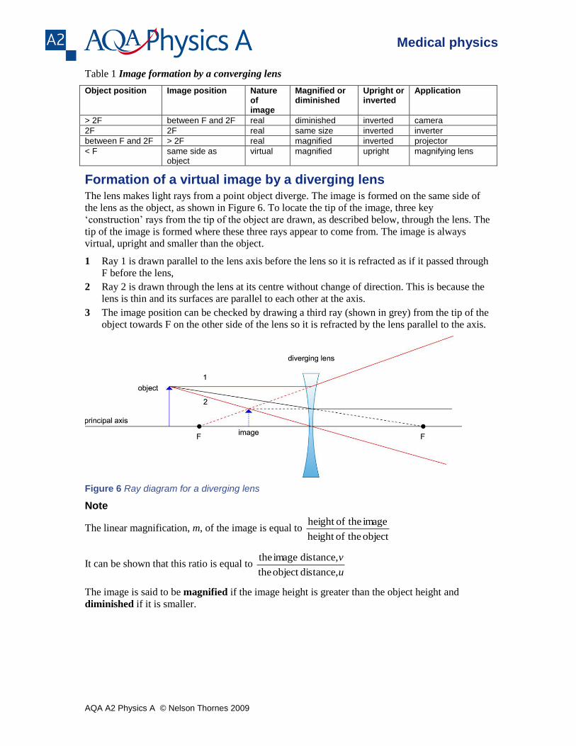
Formation of a virtual image by a diverging lens The lens makes light rays from a point object diverge. The image is formed on the same side of
the lens as the object, as shown in Figure 6. To locate the tip of the image, three key
‘construction’ rays from the tip of the object are drawn, as described below, through the lens. The
tip of the image is formed where these three rays appear to come from. The image is always
virtual, upright and smaller than the object.
1 Ray 1 is drawn parallel to the lens axis before the lens so it is refracted as if it passed through
F before the lens,
2 Ray 2 is drawn through the lens at its centre without change of direction. This is because the
lens is thin and its surfaces are parallel to each other at the axis.
3 The image position can be checked by drawing a third ray (shown in grey) from the tip of the
object towards F on the other side of the lens so it is refracted by the lens parallel to the axis.
Figure 6 Ray diagram for a diverging lens
Note
The linear magnification, m, of the image is equal to object theofheight
image theofheight
It can be shown that this ratio is equal to u
v
distance,object the
distance, image the
The image is said to be magnified if the image height is greater than the object height and
diminished if it is smaller.

AQA A2 Physics A © Nelson Thornes 2009
Medical physics
When you draw a ray diagram, make sure you choose a suitably large scale that enables you to fit the object and the image on your diagram. Use a ruler to make sure your lines are straight!
The lens formula
For an object on the principal axis of a thin lens of focal length f at distance u from the lens, the
distance from the image to the lens, v, is given by:
fvu
111
Notes
1 Proof of the lens formula is not required in the option specification.
2 When numerical values are substituted into the formula, the sign convention ‘real is positive;
virtual is negative’ is used for the object and image distances. The focal length, f, of a
converging lens is always assigned a positive value. A diverging lens is always assigned a
negative value.
Worked example
An object is placed on the principal axis of a convex lens of focal length 150 mm at a distance of
200 mm from the centre of the lens.
a Calculate the image distance.
b State whether the image is real or virtual.
Solution
a f = + 0.150 m, u = + 0.200
m
Using the lens formula fvu
11
1 gives
150.0
11
200.0
1
v
Hence 200.0
1
150.0
11
v = 6.67 − 5.00 = 1.67
Therefore v = + 0.600 m
b The image is real (because v is positive).

AQA A2 Physics A © Nelson Thornes 2009
Medical physics
Summary questions
1 a i Copy and complete the ray diagram in Figure 7 to show how a converging lens in a camera forms
an image of an object.
Figure 7
ii State whether the image in Figure 6 is real or virtual, magnified or diminished, upright or
inverted.
b i Draw a ray diagram to show how a converging lens is used as a magnifying glass.
ii State whether the image in your diagram is real or virtual, magnified or diminished, upright or
inverted.
2 An object is placed on the principal axis of a thin converging lens at a distance of 400 mm from the
centre of the lens. The lens has a focal length of 150 mm.
a Draw a ray diagram to determine the distance from the image to the lens.
b State whether the image is:
i real or virtual
ii upright or inverted.
c Use the lens formula to check the accuracy of your ray diagram.
3 An object is placed on the principal axis of a thin converging lens at a distance of 100 mm from the
centre of the lens. The lens has a focal length of 150 mm.
a Draw a ray diagram to determine the distance from the image to the lens.
b State whether the image is:
i real or virtual
ii upright or inverted.
c Use the lens formula to check the accuracy of your ray diagram.
4 An object of height 10 mm is placed on the principal axis of a diverging lens of focal length 0.200
m.
Calculate the image distance and the height of the image for an object distance of:
a 0.150 m
b 0.250 m

AQA A2 Physics A © Nelson Thornes 2009
Medical physics
1.3 Defects of vision
Learning objectives:
What do we mean by the power of a lens?
What causes myopia (short sight) and hypermetropia (long sight) and how are they corrected?
What is astigmatism and how is it corrected?
Lens power
The power of a lens is defined as metres in length focal its
1
The unit of power is the dioptre (D). For example, for:
a converging lens with a focal length of 0.20 m (f = + 0.20
m), its lens power = +5.0
D
a diverging lens with a focal length of 0.25 m (f = −0.25
m), its lens power = −4.0
D.
The eye is capable of focusing objects at different distances. This process is called
accommodation and is achieved by automatic adjustment of the thickness of the eye lens. A
normal eye can see objects in focus in the range from infinity to 25 cm. In other words, the
normal eye has a near point of 25 cm and a far point at infinity. A normal eye is that of a
40-year-old person with normal vision. Young people have a much wider range but the range
decreases gradually with age.
For near objects, the eye lens must be thicker and hence more powerful than for distant
objects. Figure 1(a) shows the light rays from a nearby object brought to a focus on the retina.
For distant objects, the eye lens must be thinner and hence less powerful than for distant
objects. Figure 1(b) shows the light rays from a distant object brought to a focus on the retina.
Figure 1 The normal eye

AQA A2 Physics A © Nelson Thornes 2009
Medical physics
Myopia and hypermetropia
Myopia or short-sight occurs when an eye cannot focus on distant objects. The uncorrected far
point of the defective eye is nearer than infinity. This is because the eye muscles cannot make the
eye lens thin enough to focus an image on the retina of an object at infinity. The eye can focus
nearby objects hence the defect is referred to as ‘short-sight’.
The cause of myopia is that light, after passing through the eye lens, converges in front of the
retina, as shown in Figure 2. This happens if the eye lens cannot become thin enough to focus
light onto the retina or if the eyeball is too long.
To correct myopia using a lens, a diverging lens of a suitable focal length must be placed in front
of the eye as shown in Figure 2. The correcting lens makes parallel rays from a distant object
diverge so they appear to come from the uncorrected far point. Therefore, the correcting lens for
myopia must:
be a diverging lens
have a focal length equal to the distance from the eye to the uncorrected far point.
Figure 2 Myopia and its correction
Figure 2 shows that:
the correcting lens forms a virtual image of the distant point object at the uncorrected far
point
the cornea and eye lens see the object as if it was at the uncorrected far point and form a real
image of the object on the retina.
Note
The correcting lens effectively moves the far point of the uncorrected eye to infinity. It also
‘moves’ the near point away as shown in Figure 3. The correcting lens makes the image of an
object placed at the least distance of distinct vision (i.e. ‘new’ near point) appear at the ‘unaided’
near point. Therefore, the image is virtual and nearer the lens than the object as shown.

AQA A2 Physics A © Nelson Thornes 2009
Medical physics
Figure 3 Effect on the near point
In Figure 3, if the object is at distance u and the image is at distance v, applying the lens formula
fvu
11
1 gives
ufv
111
Since f is negative (as the correcting lens is a diverging lens), v
1 is more negative than
u
1 so the
distance to the ‘unaided’ near-point (i.e. image distance v) is smaller than the ‘new’ near-point
distance (i.e. object distance u).
Worked example
A short-sighted eye has a far point of 5.00 m and a near point of 0.25
m.
a State the type of lens needed to correct this defect and calculate the power of the correcting lens.
b Calculate the distance from the lens to the near point of the eye with the correcting lens in front of
the eye.
Solution
a A diverging lens is needed. Its focal length is −5.0 m (= the distance to its far point).
Therefore the power of the correcting lens = f
1 = −0.20
D.
b Let u = least distance of distinct vision to an object with the correcting lens in place.
The image of this object is a virtual image formed at 0.25 m from the eye. Hence v = −0.25
m
Using fvu
11
1 with v = −0.25
m and f = −5.0
m gives
vfu
111 m3.80 4.00 0.20
25.0
1
0.5
1 1
Hence u = 3.80
1 = 0.26(3)
m
Hypermetropia or long-sight occurs when an eye cannot focus on nearby objects. The
uncorrected near point of the defective eye is further away than 25 cm. This is because the eye
muscles cannot make the eye lens thick enough to focus an image on the retina of an object 25 cm
away. The eye can focus distant objects hence the defect is referred to as ‘long-sight’.

AQA A2 Physics A © Nelson Thornes 2009
Medical physics
The cause of hypermetropia is that light, after passing through the eye lens, does not converge
enough to form an image on the retina, as shown in Figure 4. This happens if the eye lens cannot
become thick enough to focus light onto the retina or if the eyeball is too short.
Figure 4 Hypermetropia
To correct hypermetropia using a lens, a converging lens of a suitable focal length must be placed
in front of the eye as shown in Figure 5. The correcting lens makes the rays from an object 25 cm
away diverge less so they appear to come from the uncorrected near point. Therefore, the
correcting lens for hypermetropia must:
be a converging lens
have a focal length which makes an object placed 25 cm from the eye appear as if it is at the
uncorrected near point.
Figure 5 Correction of hypermetropia
Figure 5 shows that:
the correcting lens forms a virtual image of the point object at the uncorrected near point
the cornea and eye lens see the object as if it was at the uncorrected near point and form a real
image of the object on the retina.
Note
The correcting lens effectively moves the near point of the uncorrected eye nearer the lens to
25 cm away (the near point of a normal eye). It also ‘moves’ the far point from infinity nearer to
the eye as shown in Figure 6. The correcting lens makes the image of an object at the ‘new’ far
point appear to be at infinity.

AQA A2 Physics A © Nelson Thornes 2009
Medical physics
Figure 6 Effect on the far point
In Figure 6, the object must be at the focal point of the converging lens for the rays to become
parallel after the lens to make the image appear to be at infinity. Therefore, the new far point is at
distance f from the lens, where f is the focal length of the lens.
Worked example
A long-sighted eye has the far point at infinity and a near point which is 40 cm from the eye.
a State the type of lens needed to correct this defect and calculate the power of the correcting lens.
b Calculate the distance from the lens to the far point of the eye with the correcting lens in front of the
eye.
Solution
a A converging lens is needed.
For an object at 25 cm from the eye, the object distance u = +25
cm = +0.25
m
The lens must form a virtual image of the object at the uncorrected near point of the eye.
Hence the image distance v = −40 cm
Using fvu
11
1 with u = +0.25
m and v = −0.40
m gives
40.0
1
25.0
11
f = 4.00 − 2.50 = 1.50
Hence the power of the correcting lens = f
1 = +1.50
D
b The distance from the lens to the ‘new’ far point = f = 50.1
1 = 0.67
m
AQA A2 Physics A © Nelson Thornes 2009
Medical physics
Astigmatism
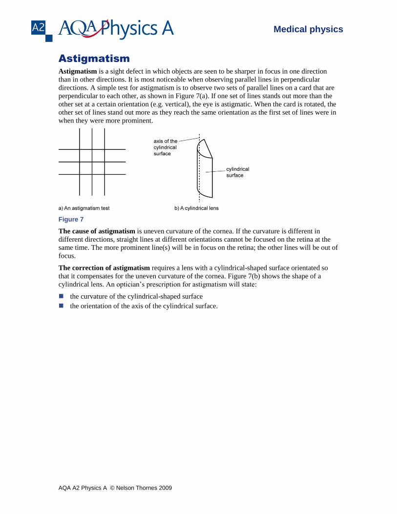
Astigmatism is a sight defect in which objects are seen to be sharper in focus in one direction
than in other directions. It is most noticeable when observing parallel lines in perpendicular
directions. A simple test for astigmatism is to observe two sets of parallel lines on a card that are
perpendicular to each other, as shown in Figure 7(a). If one set of lines stands out more than the
other set at a certain orientation (e.g. vertical), the eye is astigmatic. When the card is rotated, the
other set of lines stand out more as they reach the same orientation as the first set of lines were in
when they were more prominent.
Figure 7
The cause of astigmatism is uneven curvature of the cornea. If the curvature is different in
different directions, straight lines at different orientations cannot be focused on the retina at the
same time. The more prominent line(s) will be in focus on the retina; the other lines will be out of
focus.
The correction of astigmatism requires a lens with a cylindrical-shaped surface orientated so
that it compensates for the uneven curvature of the cornea. Figure 7(b) shows the shape of a
cylindrical lens. An optician’s prescription for astigmatism will state:
the curvature of the cylindrical-shaped surface
the orientation of the axis of the cylindrical surface.

AQA A2 Physics A © Nelson Thornes 2009
Medical physics
Summary questions
1 a State what is meant by myopia.
b i With the aid of a diagram, describe how myopia is corrected.
ii A short-sighted eye has a far point 8.0 m away. Calculate the power of the correcting lens to give
a corrected far point at infinity.
2 a State what is meant by hypermetropia.
b i With the aid of a diagram, describe how hypermetropia is corrected.
ii A long-sighted eye has a near point at 0.50 m away. Calculate the power of the correcting lens to
give a corrected near point at 25 cm from the eye.
3 a A short-sighted eye has a far point at 5.0 m away and a near point 25
cm away. Calculate:
i the power of the correcting lens needed to give a corrected far point at infinity
ii the distance from the lens to the corrected near point when the lens is in front of the eye.
b A long-sighted eye has a near point at 0.80 m away and a far point at infinity.
Calculate:
i the power of the correcting lens needed to give a corrected near point at 25 cm from the eye
ii the distance from the lens to the corrected far point when the lens is in front of the eye.
4 a State what is meant by astigmatism and explain why it occurs.
b Describe how an astigmatic eye is corrected using a suitable lens, stating what measurements need
to be made to ensure the lens is suitable.