chapter 1 introduction - medianets.humedianets.hu/wp-content/uploads/2017/11/chapter1-hit.pdf ·...
TRANSCRIPT

Introduction 1
Chapter 1
Introduction
Computer Networking: A
Top Down Approach
Featuring the Internet,
5th edition.
Jim Kurose, Keith Ross
Pearson Addison-Wesley,
2009.
A note on the use of these ppt slides:We’re making these slides freely available to all (faculty, students, readers).
They’re in PowerPoint form so you can add, modify, and delete slides
(including this one) and slide content to suit your needs. They obviously
represent a lot of work on our part. In return for use, we only ask the
following:
If you use these slides (e.g., in a class) in substantially unaltered form,
that you mention their source (after all, we’d like people to use our book!)
If you post any slides in substantially unaltered form on a www site, that
you note that they are adapted from (or perhaps identical to) our slides, and
note our copyright of this material.
Thanks and enjoy! JFK/KWR
All material copyright 1996-2010
J.F Kurose and K.W. Ross, All Rights Reserved
Communication Networks© László Bokor, Károly Farkas, Department of Networked Systems and Services
Budapest University of Technology and Economics

Introduction 2
Chapter 1: Roadmap
1.1 What is the Internet?
1.2 Network edge
1.3 Network core
1.4 Network access and physical media
1.5 Internet structure and ISPs
1.6 Delay & loss in packet-switched networks
1.7 Protocol layers, service models
1.8 History
Communication Networks© László Bokor, Károly Farkas, Department of Networked Systems and Services
Budapest University of Technology and Economics

Introduction 3
▪ Millions of connected
computing devices
• hosts = end systems
▪ Running network apps
▪ Communication links
• fiber, copper, radio, satellite
• transmission rate =
bandwidth
▪ Routers
• forward packets (chunks of
data)
local ISP
companynetwork
regional ISP
router workstation
servermobile
What’s the Internet: “Nuts and bolts” view
Communication Networks© László Bokor, Károly Farkas, Department of Networked Systems and Services
Budapest University of Technology and Economics

Introduction 4
▪ Protocols control sending,
receiving of msgs
• e.g., TCP, IP, HTTP, FTP,
PPP
▪ Internet: “network of
networks”
• loosely hierarchical
• public Internet versus private
intranet
▪ Internet standards
• RFC: Request for comments
• IETF: Internet Engineering
Task Force
local ISP
companynetwork
regional ISP
router workstation
servermobile
What’s the Internet: “Nuts and bolts” view
Communication Networks© László Bokor, Károly Farkas, Department of Networked Systems and Services
Budapest University of Technology and Economics

Introduction 5
▪ Communication
infrastructure enables
distributed applications
• web, email, games, e-
commerce, file sharing
▪ Communication services
provided to apps
• connectionless unreliable
• connection-oriented reliable
What’s the Internet: A service view
Communication Networks© László Bokor, Károly Farkas, Department of Networked Systems and Services
Budapest University of Technology and Economics

Introduction 6
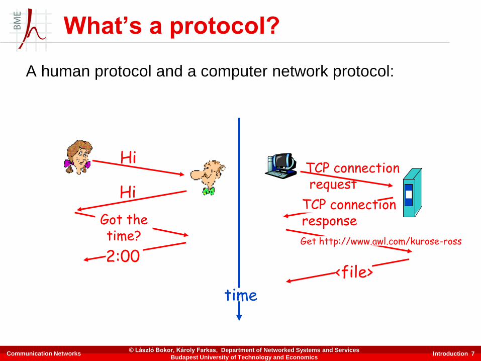
What’s a protocol?
Human protocols
▪ “What’s the time?”
▪ “I have a question”
▪ Introductions
… specific msgs sent
… specific actions taken
when msgs received,
or other events
Network protocols
▪ Machines rather than
humans
▪ All communication activity
in the Internet governed by
protocols
Protocols define format, order of
msgs sent and received among
network entities, and actions
taken on msg transmission,
receipt
Communication Networks© László Bokor, Károly Farkas, Department of Networked Systems and Services
Budapest University of Technology and Economics
Introduction 7
What’s a protocol?
A human protocol and a computer network protocol:
Hi
Hi
Got thetime?
2:00
TCP connectionrequest
TCP connectionresponse
<file>
time
Get http://www.awl.com/kurose-ross
Communication Networks© László Bokor, Károly Farkas, Department of Networked Systems and Services
Budapest University of Technology and Economics

Introduction 8
How does the Internet look like?
Communication Networks© László Bokor, Károly Farkas, Department of Networked Systems and Services
Budapest University of Technology and Economics
Introduction 9
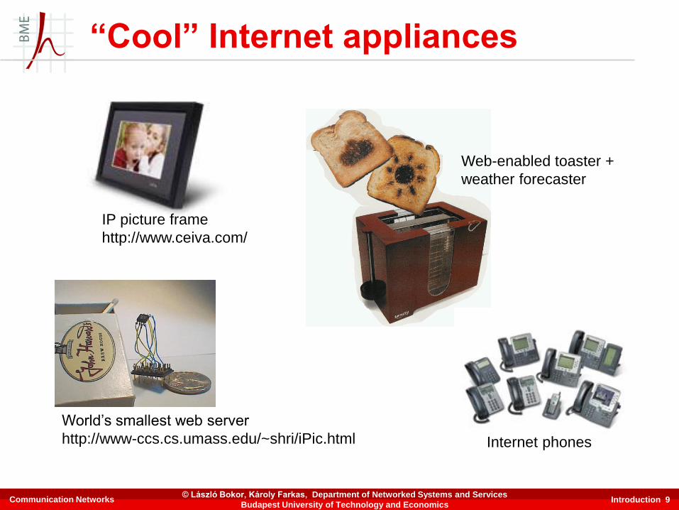
“Cool” Internet appliances
World’s smallest web server
http://www-ccs.cs.umass.edu/~shri/iPic.html
IP picture frame
http://www.ceiva.com/
Web-enabled toaster +
weather forecaster
Internet phones
Communication Networks© László Bokor, Károly Farkas, Department of Networked Systems and Services
Budapest University of Technology and Economics

Introduction 10
Chapter 1: Roadmap
1.1 What is the Internet?
1.2 Network edge
1.3 Network core
1.4 Network access and physical media
1.5 Internet structure and ISPs
1.6 Delay & loss in packet-switched networks
1.7 Protocol layers, service models
1.8 History
Communication Networks© László Bokor, Károly Farkas, Department of Networked Systems and Services
Budapest University of Technology and Economics

Introduction 11
A closer look at network structure
▪ Network edge
• applications and hosts
▪ Network core
• routers
• network of networks
▪ Access networks,
physical media
• communication links
Communication Networks© László Bokor, Károly Farkas, Department of Networked Systems and Services
Budapest University of Technology and Economics

Introduction 12
The network edge
▪ End systems (hosts)• run application programs
• e.g. Web, email
• at “edge of network”
▪ Client/server model• client host requests, receives
service from always-on server
• e.g. Web browser/server; email
client/server
▪ Peer-peer model• minimal (or no) use of dedicated
servers
• e.g. Skype, BitTorrent, KaZaA
Communication Networks© László Bokor, Károly Farkas, Department of Networked Systems and Services
Budapest University of Technology and Economics
Introduction 13
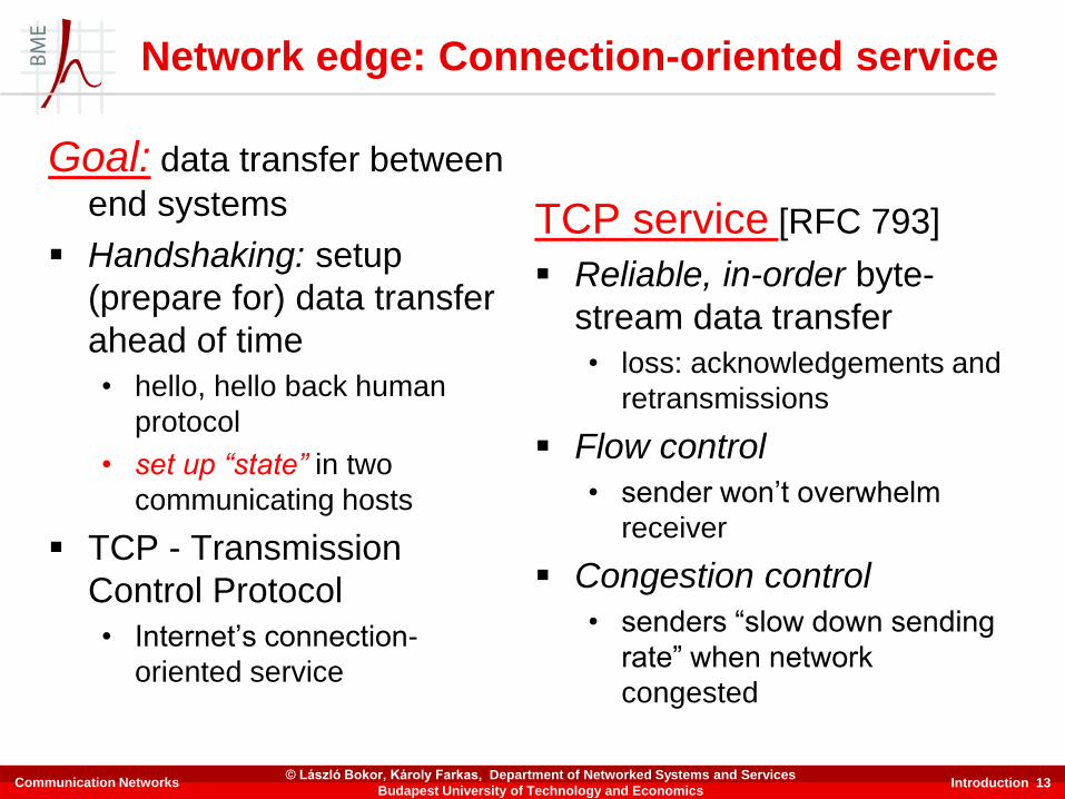
Goal: data transfer between
end systems
▪ Handshaking: setup
(prepare for) data transfer
ahead of time
• hello, hello back human
protocol
• set up “state” in two
communicating hosts
▪ TCP - Transmission
Control Protocol
• Internet’s connection-
oriented service
TCP service [RFC 793]
▪ Reliable, in-order byte-
stream data transfer
• loss: acknowledgements and
retransmissions
▪ Flow control
• sender won’t overwhelm
receiver
▪ Congestion control
• senders “slow down sending
rate” when network
congested
Network edge: Connection-oriented service
Communication Networks© László Bokor, Károly Farkas, Department of Networked Systems and Services
Budapest University of Technology and Economics
Introduction 14
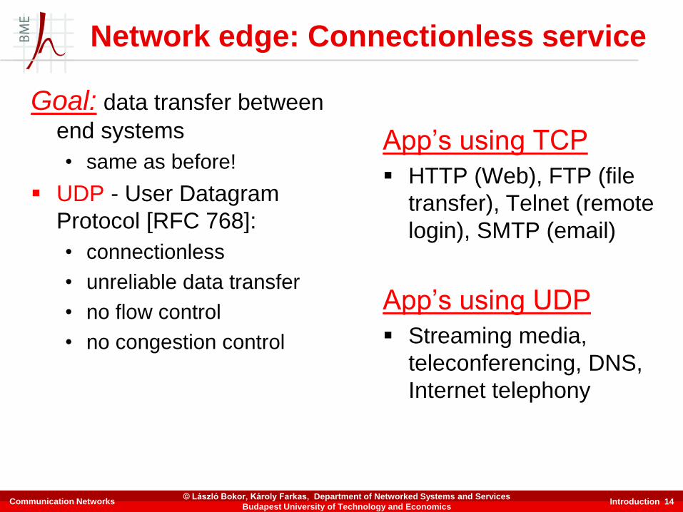
Goal: data transfer between
end systems
• same as before!
▪ UDP - User Datagram
Protocol [RFC 768]:
• connectionless
• unreliable data transfer
• no flow control
• no congestion control
App’s using TCP
▪ HTTP (Web), FTP (file
transfer), Telnet (remote
login), SMTP (email)
App’s using UDP
▪ Streaming media,
teleconferencing, DNS,
Internet telephony
Network edge: Connectionless service
Communication Networks© László Bokor, Károly Farkas, Department of Networked Systems and Services
Budapest University of Technology and Economics

Introduction 15
Chapter 1: Roadmap
1.1 What is the Internet?
1.2 Network edge
1.3 Network core
1.4 Network access and physical media
1.5 Internet structure and ISPs
1.6 Delay & loss in packet-switched networks
1.7 Protocol layers, service models
1.8 History
Communication Networks© László Bokor, Károly Farkas, Department of Networked Systems and Services
Budapest University of Technology and Economics

Introduction 16
The network core
▪ Mesh of interconnected
routers
▪ The fundamental
question: how is data
transferred through net?• Circuit-switching
• dedicated circuit per call:
telephone net
• Packet-switching
• data sent thru net in
discrete “chunks”
Communication Networks© László Bokor, Károly Farkas, Department of Networked Systems and Services
Budapest University of Technology and Economics
Introduction 17
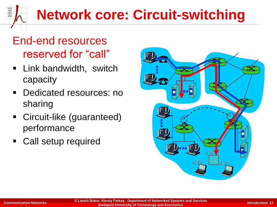
Network core: Circuit-switching
End-end resources
reserved for “call”
▪ Link bandwidth, switch
capacity
▪ Dedicated resources: no
sharing
▪ Circuit-like (guaranteed)
performance
▪ Call setup required
Communication Networks© László Bokor, Károly Farkas, Department of Networked Systems and Services
Budapest University of Technology and Economics
Introduction 18
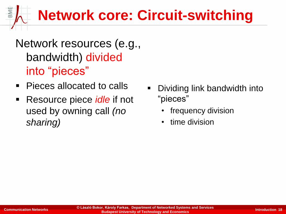
Network core: Circuit-switching
Network resources (e.g.,
bandwidth) divided
into “pieces”
▪ Pieces allocated to calls
▪ Resource piece idle if not
used by owning call (no
sharing)
▪ Dividing link bandwidth into
“pieces”
• frequency division
• time division
Communication Networks© László Bokor, Károly Farkas, Department of Networked Systems and Services
Budapest University of Technology and Economics

Introduction 19
FDM
bandwidth/
frequency
of the link
time
Time Domain Mux (TDM)Transmission rate of single circuit = frame rate in frames/sec * #bits in a slot
bandwidth/
frequency
of the link
time
4 users
Example:
Circuit-switching: FDM and TDM
Communication Networks
Slot
(here time is divided
into 4 slots/frame)
© László Bokor, Károly Farkas, Department of Networked Systems and Services
Budapest University of Technology and Economics

Introduction 21
Network core: Packet-switching
Each end-end data stream
divided into packets
▪ User A, B packets share
network resources
▪ Each packet uses full link
bandwidth
▪ Resources used as needed
Resource contention
▪ Aggregate resource
demand can exceed
amount available
▪ Congestion: packets
queue, wait for link use
▪ Store and forward: packets
move one hop at a time
• node receives complete
packet before forwardingBandwidth division into “pieces”
Dedicated allocation
Resource reservation
Communication Networks© László Bokor, Károly Farkas, Department of Networked Systems and Services
Budapest University of Technology and Economics

Introduction 22
Sequence of A & B packets does not have fixed pattern, shared on demand statistical multiplexing
TDM: each host gets the same slot in revolving TDM frame.
A
B
C100 Mb/sEthernet
1.5 Mb/s
D E
statistical multiplexing
queue of packetswaiting for output
link
Packet switching: Statistical multiplexing
Communication Networks© László Bokor, Károly Farkas, Department of Networked Systems and Services
Budapest University of Technology and Economics

Introduction 23
▪ Takes L/R seconds to
transmit (push out)
packet of L bits on to link
of R bps capacity
▪ Entire packet must
arrive at router before it
can be transmitted on
next link: store-and-
forward
▪ delay = 3L/R (assuming
zero propagation delay)
Example:
▪ L = 7.5 Mbits
▪ R = 1.5 Mbps
▪ delay = 15 sec
R R R
L
more on delay shortly …
Packet switching: Store-and-forward
Communication Networks© László Bokor, Károly Farkas, Department of Networked Systems and Services
Budapest University of Technology and Economics
Introduction 24
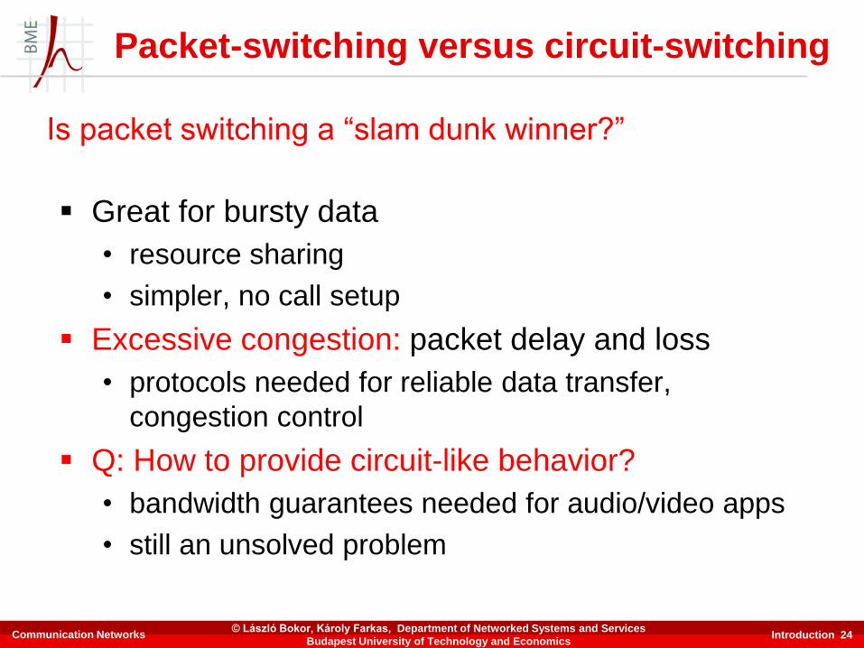
▪ Great for bursty data
• resource sharing
• simpler, no call setup
▪ Excessive congestion: packet delay and loss
• protocols needed for reliable data transfer,
congestion control
▪ Q: How to provide circuit-like behavior?
• bandwidth guarantees needed for audio/video apps
• still an unsolved problem
Is packet switching a “slam dunk winner?”
Packet-switching versus circuit-switching
Communication Networks© László Bokor, Károly Farkas, Department of Networked Systems and Services
Budapest University of Technology and Economics

Introduction 25
Chapter 1: Roadmap
1.1 What is the Internet?
1.2 Network edge
1.3 Network core
1.4 Network access and physical media
1.5 Internet structure and ISPs
1.6 Delay & loss in packet-switched networks
1.7 Protocol layers, service models
1.8 History
Communication Networks© László Bokor, Károly Farkas, Department of Networked Systems and Services
Budapest University of Technology and Economics

Introduction 26
Q: How to connect end
systems to edge router?
▪ Residential access nets
▪ Institutional access
networks (school,
company)
▪ Mobile access networks
Keep in mind
▪ Bandwidth (bits per
second) of access
network?
▪ Shared or dedicated?
Access networks and physical media
Communication Networks© László Bokor, Károly Farkas, Department of Networked Systems and Services
Budapest University of Technology and Economics

Introduction 27
▪ Dialup via modem
• Up to 56 Kbps direct access to
router (often less)
• Can’t surf and phone at same
time: can’t be “always on”
Residential access: Point-to-point access
▪ ADSL: Asymmetric Digital Subscriber Lline
• Up to 1 Mbps upstream (today typically 512-1024 kbps)
• Up to 8 Mbps downstream (today typically 5-10 Mbps)
• FDM: 50 kHz - 1 MHz for downstream
4 kHz - 50 kHz for upstream
0 kHz - 4 kHz for ordinary telephone
Communication Networks© László Bokor, Károly Farkas, Department of Networked Systems and Services
Budapest University of Technology and Economics
Introduction 28
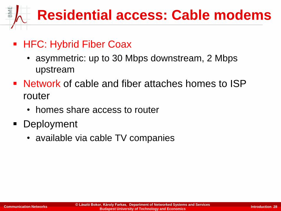
▪ HFC: Hybrid Fiber Coax
• asymmetric: up to 30 Mbps downstream, 2 Mbps
upstream
▪ Network of cable and fiber attaches homes to ISP
router
• homes share access to router
▪ Deployment
• available via cable TV companies
Residential access: Cable modems
Communication Networks© László Bokor, Károly Farkas, Department of Networked Systems and Services
Budapest University of Technology and Economics

Introduction 29
Residential access: Cable modems
Communication Networks© László Bokor, Károly Farkas, Department of Networked Systems and Services
Budapest University of Technology and Economics

Introduction 30
home
cable headend
cable distribution
network (simplified)
Typically 500 to 5,000 homes
Cable network architecture: Overview
Communication Networks© László Bokor, Károly Farkas, Department of Networked Systems and Services
Budapest University of Technology and Economics

Introduction 31
home
cable headend
cable distribution
network (simplified)
server(s)
Cable network architecture: Overview
Communication Networks© László Bokor, Károly Farkas, Department of Networked Systems and Services
Budapest University of Technology and Economics

Introduction 32
home
cable headend
cable distribution
network (simplified)
Cable network architecture: Overview
Communication Networks© László Bokor, Károly Farkas, Department of Networked Systems and Services
Budapest University of Technology and Economics

Introduction 33
home
cable headend
cable distribution
network (simplified)
Channels
V
I
D
E
O
V
I
D
E
O
V
I
D
E
O
V
I
D
E
O
V
I
D
E
O
V
I
D
E
O
D
A
T
A
D
A
T
A
C
O
N
T
R
O
L
1 2 3 4 5 6 7 8 9
FDM:
Cable network architecture: Overview
Communication Networks© László Bokor, Károly Farkas, Department of Networked Systems and Services
Budapest University of Technology and Economics
Introduction 34
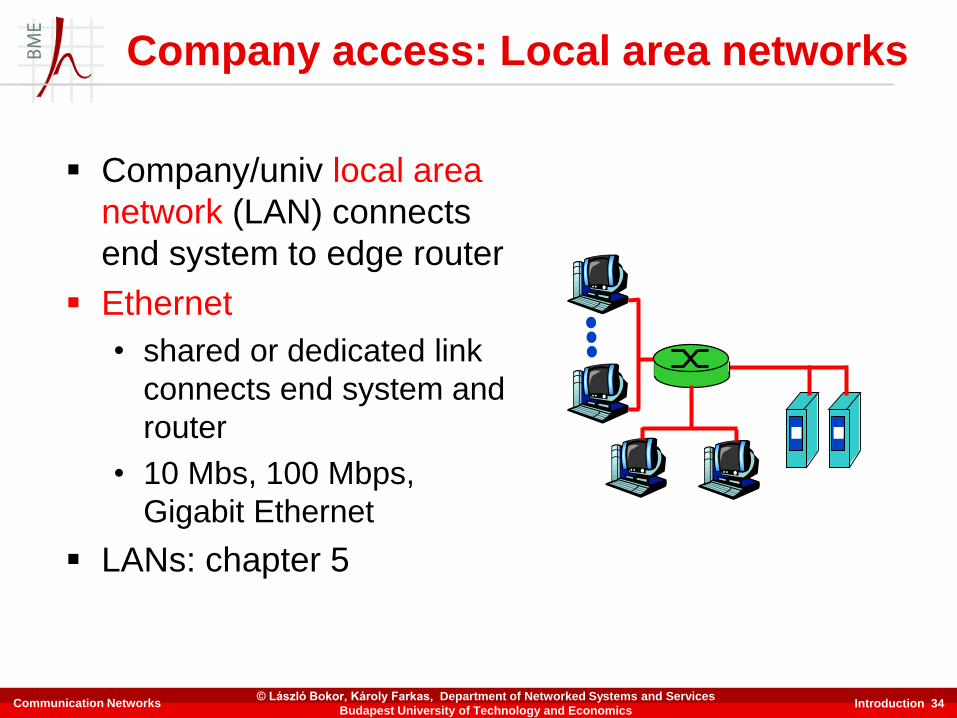
▪ Company/univ local area
network (LAN) connects
end system to edge router
▪ Ethernet
• shared or dedicated link
connects end system and
router
• 10 Mbs, 100 Mbps,
Gigabit Ethernet
▪ LANs: chapter 5
Company access: Local area networks
Communication Networks© László Bokor, Károly Farkas, Department of Networked Systems and Services
Budapest University of Technology and Economics

Introduction 35
▪ Shared wireless access
network connects end system
to router
• via base station aka “access
point”
▪ Wireless LANs
• 802.11b/g/n (WiFi): 11/54/600
Mbps
▪ Wider-area wireless access
• provided by telco operator
• GPRS in Europe/US
• 3G ~ 384 kbps (UMTS)
• 4G ~ couple Mbps (LTE)
basestation
mobilehosts
router
Wireless access networks
Communication Networks© László Bokor, Károly Farkas, Department of Networked Systems and Services
Budapest University of Technology and Economics
Introduction 36
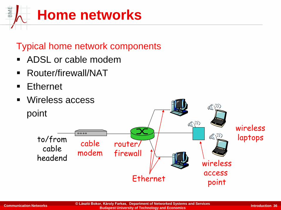
Typical home network components
▪ ADSL or cable modem
▪ Router/firewall/NAT
▪ Ethernet
▪ Wireless access
point
wirelessaccess point
wirelesslaptops
router/firewall
cablemodem
to/fromcable
headend
Ethernet
Home networks
Communication Networks© László Bokor, Károly Farkas, Department of Networked Systems and Services
Budapest University of Technology and Economics
Introduction 37
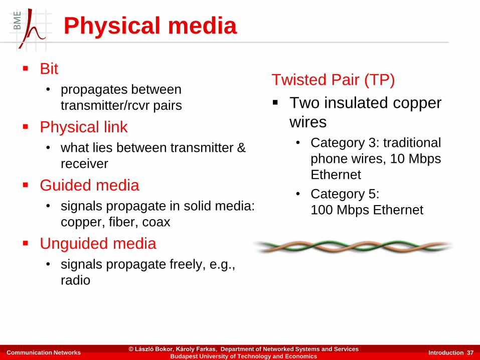
Physical media
▪ Bit
• propagates between
transmitter/rcvr pairs
▪ Physical link
• what lies between transmitter &
receiver
▪ Guided media
• signals propagate in solid media:
copper, fiber, coax
▪ Unguided media
• signals propagate freely, e.g.,
radio
Twisted Pair (TP)
▪ Two insulated copper
wires
• Category 3: traditional
phone wires, 10 Mbps
Ethernet
• Category 5:
100 Mbps Ethernet
Communication Networks© László Bokor, Károly Farkas, Department of Networked Systems and Services
Budapest University of Technology and Economics
Introduction 38
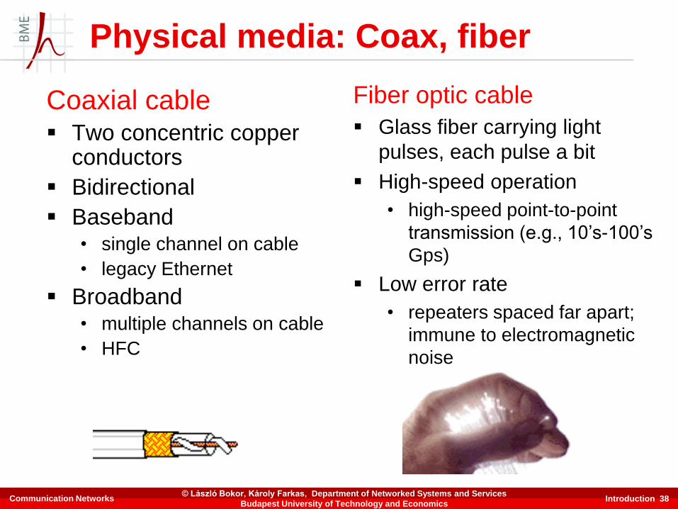
Coaxial cable▪ Two concentric copper
conductors
▪ Bidirectional
▪ Baseband• single channel on cable
• legacy Ethernet
▪ Broadband• multiple channels on cable
• HFC
Fiber optic cable
▪ Glass fiber carrying light
pulses, each pulse a bit
▪ High-speed operation
• high-speed point-to-point
transmission (e.g., 10’s-100’s
Gps)
▪ Low error rate
• repeaters spaced far apart;
immune to electromagnetic
noise
Physical media: Coax, fiber
Communication Networks© László Bokor, Károly Farkas, Department of Networked Systems and Services
Budapest University of Technology and Economics
Introduction 39
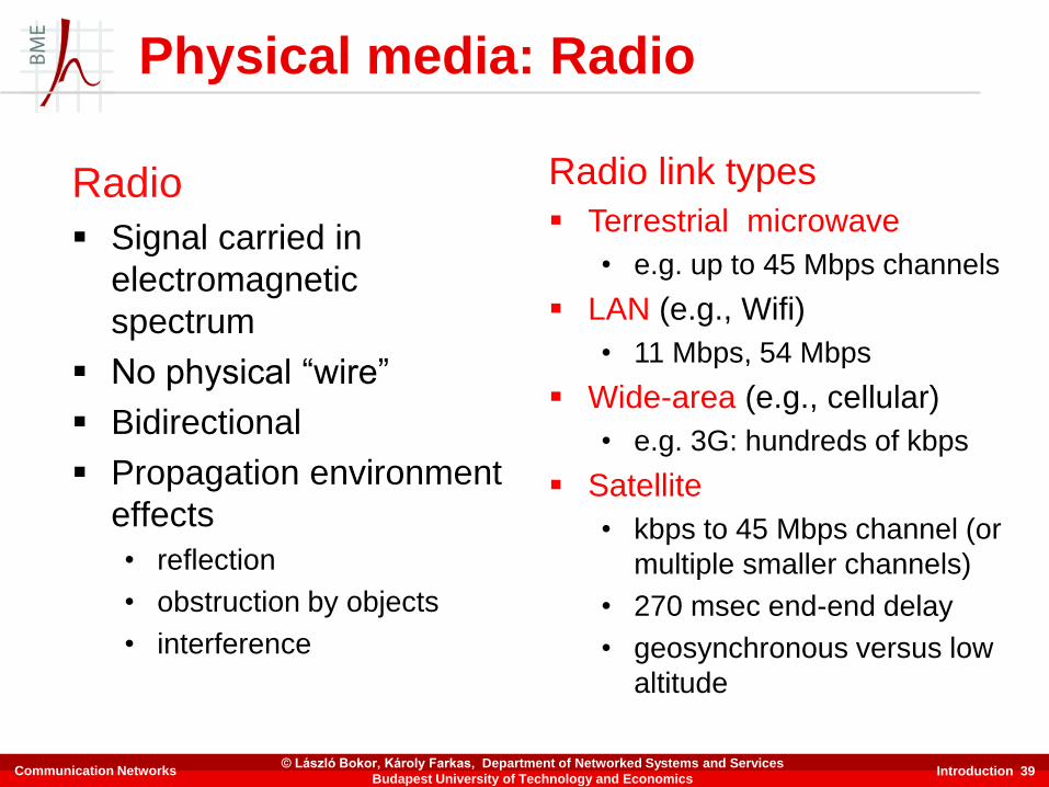
Radio
▪ Signal carried in
electromagnetic
spectrum
▪ No physical “wire”
▪ Bidirectional
▪ Propagation environment
effects
• reflection
• obstruction by objects
• interference
Radio link types
▪ Terrestrial microwave
• e.g. up to 45 Mbps channels
▪ LAN (e.g., Wifi)
• 11 Mbps, 54 Mbps
▪ Wide-area (e.g., cellular)
• e.g. 3G: hundreds of kbps
▪ Satellite
• kbps to 45 Mbps channel (or
multiple smaller channels)
• 270 msec end-end delay
• geosynchronous versus low
altitude
Physical media: Radio
Communication Networks© László Bokor, Károly Farkas, Department of Networked Systems and Services
Budapest University of Technology and Economics
Introduction 40
Chapter 1: Roadmap
1.1 What is the Internet?
1.2 Network edge
1.3 Network core
1.4 Network access and physical media
1.5 Internet structure and ISPs
1.6 Delay & loss in packet-switched networks
1.7 Protocol layers, service models
1.8 History
Communication Networks© László Bokor, Károly Farkas, Department of Networked Systems and Services
Budapest University of Technology and Economics

Introduction 41
▪ Roughly hierarchical
▪ At center: “tier-1” ISPs (e.g., MCI, Sprint, AT&T, Cable and
Wireless), national/international coverage
• treat each other as equals
Tier 1 ISP
Tier 1 ISP
Tier 1 ISP
Tier-1 providers interconnect (peer) privately
NAP
Tier-1 providers also interconnect at public network access points (NAPs)
Internet structure: Network of networks
Communication Networks© László Bokor, Károly Farkas, Department of Networked Systems and Services
Budapest University of Technology and Economics
Introduction 42
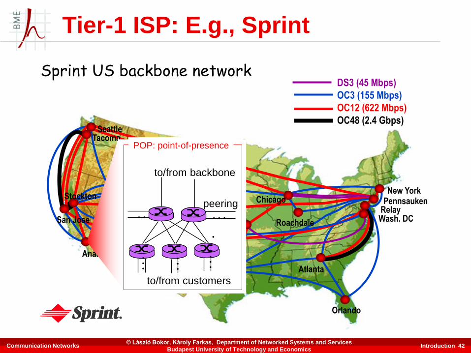
Tier-1 ISP: E.g., Sprint
Sprint US backbone network
Seattle
Atlanta
Chicago
Roachdale
Stockton
San Jose
Anaheim
Fort Worth
Orlando
Kansas City
CheyenneNew York
PennsaukenRelayWash. DC
Tacoma
DS3 (45 Mbps)
OC3 (155 Mbps)
OC12 (622 Mbps)
OC48 (2.4 Gbps)
…
to/from customers
peering
to/from backbone
…
.
………POP: point-of-presence
Communication Networks© László Bokor, Károly Farkas, Department of Networked Systems and Services
Budapest University of Technology and Economics

Introduction 43
▪ “Tier-2” ISPs: smaller (often regional) ISPs
• Connect to one or more tier-1 ISPs, possibly other tier-2 ISPs
Tier 1 ISP
Tier 1 ISP
Tier 1 ISP
NAP
Tier-2 ISPTier-2 ISP
Tier-2 ISP Tier-2 ISP
Tier-2 ISP
Tier-2 ISP pays tier-1 ISP for connectivity to rest of Internet tier-2 ISP is customer oftier-1 provider
Tier-2 ISPs also peer privately with each other, interconnect at NAP
Internet structure: Network of networks
Communication Networks© László Bokor, Károly Farkas, Department of Networked Systems and Services
Budapest University of Technology and Economics
Introduction 44
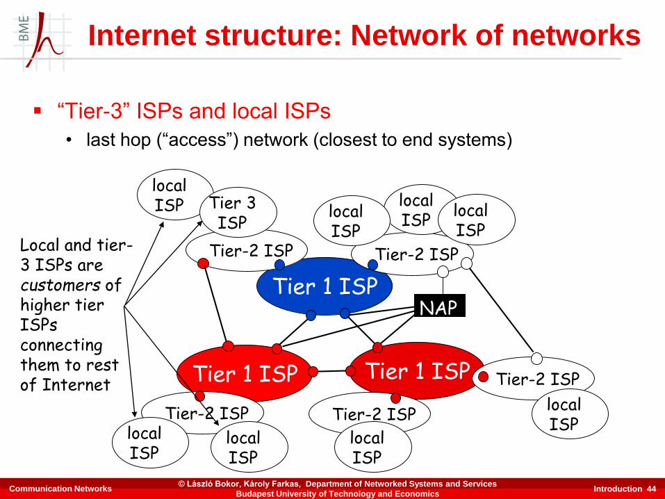
▪ “Tier-3” ISPs and local ISPs
• last hop (“access”) network (closest to end systems)
Tier 1 ISP
Tier 1 ISP
Tier 1 ISP
NAP
Tier-2 ISPTier-2 ISP
Tier-2 ISP Tier-2 ISP
Tier-2 ISP
localISPlocal
ISPlocalISP
localISP
localISP Tier 3
ISP
localISP
localISP
localISP
Local and tier-3 ISPs are customers ofhigher tier ISPsconnecting them to rest of Internet
Internet structure: Network of networks
Communication Networks© László Bokor, Károly Farkas, Department of Networked Systems and Services
Budapest University of Technology and Economics
Introduction 45
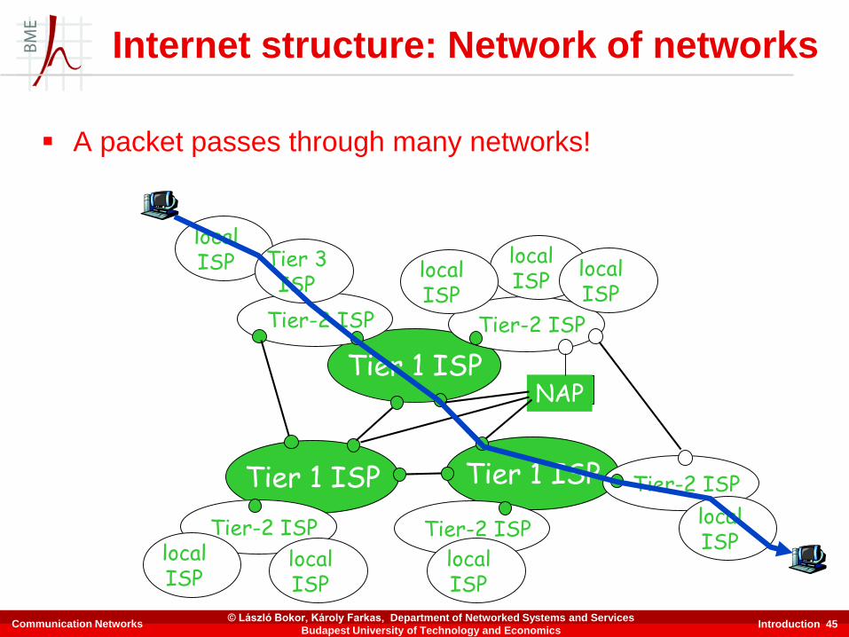
▪ A packet passes through many networks!
Tier 1 ISP
Tier 1 ISP
Tier 1 ISP
NAP
Tier-2 ISPTier-2 ISP
Tier-2 ISP Tier-2 ISP
Tier-2 ISP
localISPlocal
ISPlocalISP
localISP
localISP Tier 3
ISP
localISP
localISP
localISP
Internet structure: Network of networks
Communication Networks© László Bokor, Károly Farkas, Department of Networked Systems and Services
Budapest University of Technology and Economics

Introduction 46
Chapter 1: Roadmap
1.1 What is the Internet?
1.2 Network edge
1.3 Network core
1.4 Network access and physical media
1.5 Internet structure and ISPs
1.6 Delay & loss in packet-switched networks
1.7 Protocol layers, service models
1.8 History
Communication Networks© László Bokor, Károly Farkas, Department of Networked Systems and Services
Budapest University of Technology and Economics

Introduction 47
Packets queue in router buffers
▪ Packet arrival rate to link exceeds output link capacity
▪ Packets queue, wait for turn
packet being transmitted (delay)
packets queueing (delay)
free (available) buffers: arriving packets dropped (loss) if no free buffers
How do loss and delay occur?
A
B
Communication Networks© László Bokor, Károly Farkas, Department of Networked Systems and Services
Budapest University of Technology and Economics

Introduction 48
1. Nodal processing
▪ check bit errors
▪ determine output link
A
B
propagation
transmission
nodalprocessing queueing
2. Queueing
▪ time waiting at output
link for transmission
▪ depends on congestion
level of router
Four sources of packet delay
Communication Networks© László Bokor, Károly Farkas, Department of Networked Systems and Services
Budapest University of Technology and Economics

Introduction 49
3. Transmission delay
▪ R=link bandwidth (bps)
▪ L=packet length (bits)
▪ time to send bits into
link = L/R
4. Propagation delay
▪ d = length of physical link
▪ s = propagation speed in
medium (~2x10⁸ m/sec)
▪ propagation delay = d/s
A
B
propagation
transmission
nodalprocessing queueing
Note: s and R are very
different quantities!
Delay in packet-switched networks
Communication Networks© László Bokor, Károly Farkas, Department of Networked Systems and Services
Budapest University of Technology and Economics
Introduction 50
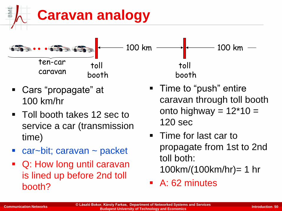
▪ Cars “propagate” at
100 km/hr
▪ Toll booth takes 12 sec to
service a car (transmission
time)
▪ car~bit; caravan ~ packet
▪ Q: How long until caravan
is lined up before 2nd toll
booth?
▪ Time to “push” entire
caravan through toll booth
onto highway = 12*10 =
120 sec
▪ Time for last car to
propagate from 1st to 2nd
toll both:
100km/(100km/hr)= 1 hr
▪ A: 62 minutes
toll booth
toll booth
ten-car caravan
100 km 100 km
Caravan analogy
Communication Networks© László Bokor, Károly Farkas, Department of Networked Systems and Services
Budapest University of Technology and Economics
Introduction 51
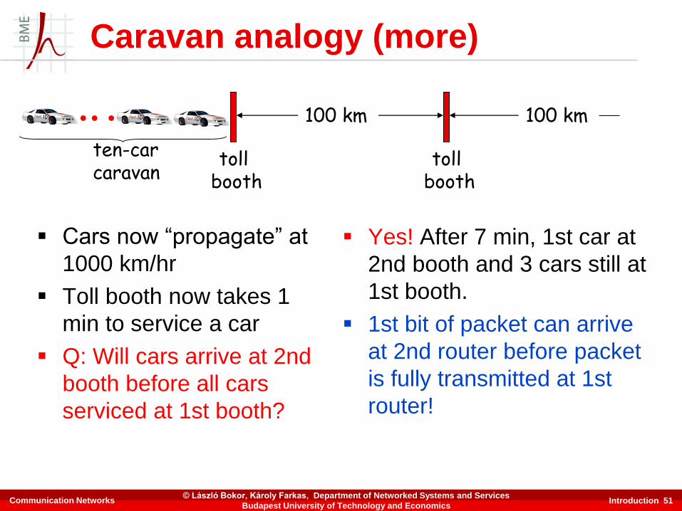
▪ Cars now “propagate” at
1000 km/hr
▪ Toll booth now takes 1
min to service a car
▪ Q: Will cars arrive at 2nd
booth before all cars
serviced at 1st booth?
▪ Yes! After 7 min, 1st car at
2nd booth and 3 cars still at
1st booth.
▪ 1st bit of packet can arrive
at 2nd router before packet
is fully transmitted at 1st
router!
toll booth
toll booth
ten-car caravan
100 km 100 km
Caravan analogy (more)
Communication Networks© László Bokor, Károly Farkas, Department of Networked Systems and Services
Budapest University of Technology and Economics
Introduction 52
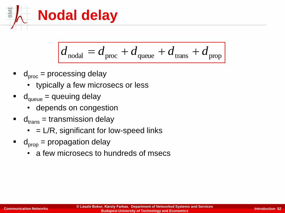
Nodal delay
▪ dproc = processing delay
• typically a few microsecs or less
▪ dqueue = queuing delay
• depends on congestion
▪ dtrans = transmission delay
• = L/R, significant for low-speed links
▪ dprop = propagation delay
• a few microsecs to hundreds of msecs
proptransqueueprocnodal ddddd
Communication Networks© László Bokor, Károly Farkas, Department of Networked Systems and Services
Budapest University of Technology and Economics

Introduction 53
“Real” Internet delays and routes
▪ What do “real” Internet delay & loss look like?
▪ Traceroute program: provides delay measurement from source to
router along end-end Internet path towards destination. For all i:
• sends three packets that will reach router i on path towards
destination
• router i will return packets to sender
• sender times interval between transmission and reply
3 probes
3 probes
3 probes
Communication Networks© László Bokor, Károly Farkas, Department of Networked Systems and Services
Budapest University of Technology and Economics

Introduction 54
“Real” Internet delays and routes
1 cs-gw (128.119.240.254) 1 ms 1 ms 2 ms2 border1-rt-fa5-1-0.gw.umass.edu (128.119.3.145) 1 ms 1 ms 2 ms3 cht-vbns.gw.umass.edu (128.119.3.130) 6 ms 5 ms 5 ms4 jn1-at1-0-0-19.wor.vbns.net (204.147.132.129) 16 ms 11 ms 13 ms 5 jn1-so7-0-0-0.wae.vbns.net (204.147.136.136) 21 ms 18 ms 18 ms 6 abilene-vbns.abilene.ucaid.edu (198.32.11.9) 22 ms 18 ms 22 ms7 nycm-wash.abilene.ucaid.edu (198.32.8.46) 22 ms 22 ms 22 ms8 62.40.103.253 (62.40.103.253) 104 ms 109 ms 106 ms9 de2-1.de1.de.geant.net (62.40.96.129) 109 ms 102 ms 104 ms10 de.fr1.fr.geant.net (62.40.96.50) 113 ms 121 ms 114 ms11 renater-gw.fr1.fr.geant.net (62.40.103.54) 112 ms 114 ms 112 ms12 nio-n2.cssi.renater.fr (193.51.206.13) 111 ms 114 ms 116 ms13 nice.cssi.renater.fr (195.220.98.102) 123 ms 125 ms 124 ms14 r3t2-nice.cssi.renater.fr (195.220.98.110) 126 ms 126 ms 124 ms15 eurecom-valbonne.r3t2.ft.net (193.48.50.54) 135 ms 128 ms 133 ms16 194.214.211.25 (194.214.211.25) 126 ms 128 ms 126 ms17 * * *18 * * *
19 fantasia.eurecom.fr (193.55.113.142) 132 ms 128 ms 136 ms
traceroute: gaia.cs.umass.edu to www.eurecom.frThree delay measurements from gaia.cs.umass.edu to cs-gw.cs.umass.edu
* means no response (probe lost, router not replying)
trans-oceaniclink
Communication Networks© László Bokor, Károly Farkas, Department of Networked Systems and Services
Budapest University of Technology and Economics

Introduction 55
Packet loss
▪ Queue (aka buffer) preceding link in buffer has finite
capacity
▪ When packet arrives in full queue, packet is dropped (aka
lost)
▪ Lost packet may be retransmitted by previous node, by
source end system, or not retransmitted at all
Communication Networks© László Bokor, Károly Farkas, Department of Networked Systems and Services
Budapest University of Technology and Economics

Introduction 56
Chapter 1: Roadmap
1.1 What is the Internet?
1.2 Network edge
1.3 Network core
1.4 Network access and physical media
1.5 Internet structure and ISPs
1.6 Delay & loss in packet-switched networks
1.7 Protocol layers, service models
1.8 History
Communication Networks© László Bokor, Károly Farkas, Department of Networked Systems and Services
Budapest University of Technology and Economics

Introduction 57
Protocol “layers”
Networks are complex!
▪ Many “pieces”
• hosts
• routers
• links of various
media
• applications
• protocols
• hardware, software
Question:
Is there any hope of
organizing structure of
network?
Or at least our discussion of
networks?
Communication Networks© László Bokor, Károly Farkas, Department of Networked Systems and Services
Budapest University of Technology and Economics

Introduction 58
Organization of air travel
▪ A series of steps
ticket (purchase)
baggage (check)
gates (load)
runway takeoff
airplane routing
ticket (complain)
baggage (claim)
gates (unload)
runway landing
airplane routing
airplane routing
Communication Networks© László Bokor, Károly Farkas, Department of Networked Systems and Services
Budapest University of Technology and Economics

Introduction 59
ticket (purchase)
baggage (check)
gates (load)
runway (takeoff)
airplane routing
departure
airportarrival
airport
intermediate air-traffic
control centers
airplane routing airplane routing
ticket (complain)
baggage (claim
gates (unload)
runway (land)
airplane routing
ticket
baggage
gate
takeoff/landing
airplane routing
Layers: each layer implements a service
• via its own internal-layer actions
• relying on services provided by layer below
Layering of airline functionality
Communication Networks© László Bokor, Károly Farkas, Department of Networked Systems and Services
Budapest University of Technology and Economics
Introduction 60
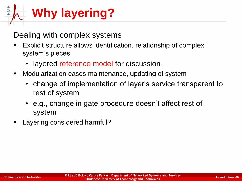
Why layering?
Dealing with complex systems
▪ Explicit structure allows identification, relationship of complex
system’s pieces
• layered reference model for discussion
▪ Modularization eases maintenance, updating of system
• change of implementation of layer’s service transparent to
rest of system
• e.g., change in gate procedure doesn’t affect rest of
system
▪ Layering considered harmful?
Communication Networks© László Bokor, Károly Farkas, Department of Networked Systems and Services
Budapest University of Technology and Economics

Introduction 61
Internet protocol stack
▪ Application: supporting network
applications
• FTP, SMTP, HTTP
▪ Transport: process-process data
transfer
• TCP, UDP
▪ Network: routing of datagrams from
source to destination
• IP, routing protocols
▪ Link: data transfer between neighboring
network elements
• PPP, Ethernet
▪ Physical: bits “on the wire”
application
transport
network
link
physical
Communication Networks© László Bokor, Károly Farkas, Department of Networked Systems and Services
Budapest University of Technology and Economics
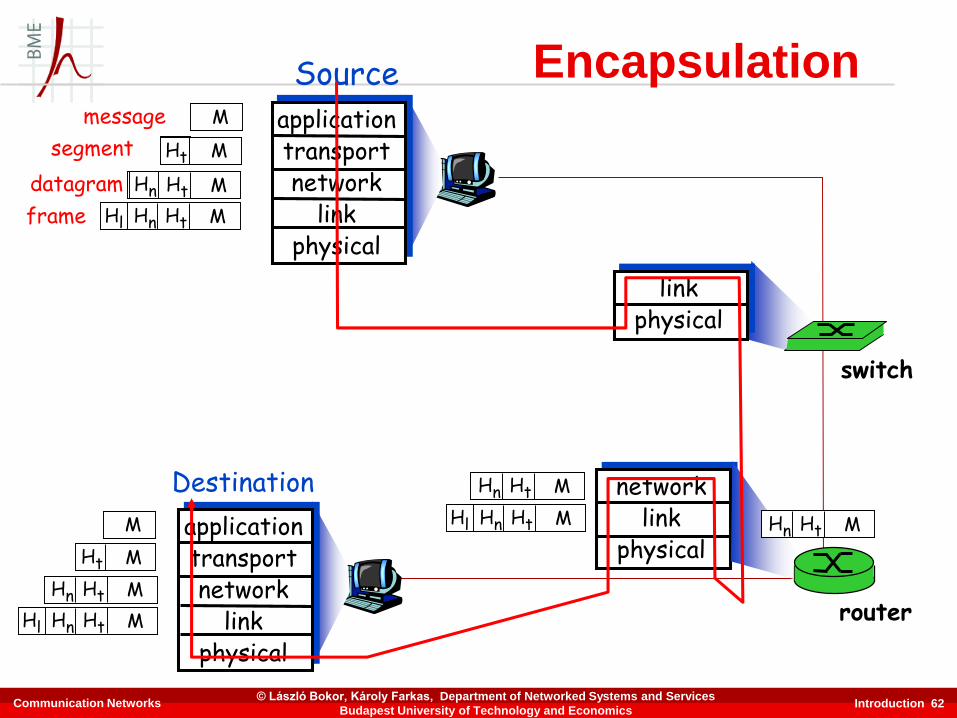
Introduction 62
Sourceapplicationtransportnetwork
linkphysical
HtHn M
segment Ht
datagram
Destination
applicationtransportnetwork
linkphysical
HtHnHl M
HtHn M
Ht M
M
networklink
physical
linkphysical
HtHnHl M
HtHn M
HtHn M
HtHnHl M
router
switch
Encapsulationmessage M
Ht M
Hn
frame
Communication Networks© László Bokor, Károly Farkas, Department of Networked Systems and Services
Budapest University of Technology and Economics
Introduction 63
Chapter 1: Roadmap
1.1 What is the Internet?
1.2 Network edge
1.3 Network core
1.4 Network access and physical media
1.5 Internet structure and ISPs
1.6 Delay & loss in packet-switched networks
1.7 Protocol layers, service models
1.8 History
Communication Networks© László Bokor, Károly Farkas, Department of Networked Systems and Services
Budapest University of Technology and Economics

Introduction 64
▪ 1961: Leonard Kleinrock -
queueing theory shows
effectiveness of packet-
switching
▪ 1964: Paul Baran - packet-
switching in military nets
▪ 1967: ARPAnet conceived
by Advanced Research
Projects Agency
▪ 1969: First ARPAnet node
operational
▪ 1972
• ARPAnet public demonstration
• NCP (Network Control Protocol)
first host-host protocol
• first e-mail program
• ARPAnet has 15 nodes
1961-1972: Early packet-switching principles
Internet history
Communication Networks© László Bokor, Károly Farkas, Department of Networked Systems and Services
Budapest University of Technology and Economics

Introduction 65
▪ 1970: ALOHAnet satellite network in Hawaii
▪ 1974: Vint Cerf and Bob Kahn - architecture for interconnecting networks
▪ 1976: Ethernet at Xerox PARC
▪ late 70’s: Proprietary architectures: DECnet, SNA, XNA
▪ late 70’s: Switching fixed length packets (ATM precursor)
▪ 1979: ARPAnet has 200 nodes
Cerf and Kahn’s internetworking principles:
• minimalism, autonomy - no internal changes required to interconnect networks
• best effort service model
• stateless routers
• decentralized control
Define today’s Internet architecture
1972-1980: Internetworking, new and proprietary nets
Internet history
Communication Networks© László Bokor, Károly Farkas, Department of Networked Systems and Services
Budapest University of Technology and Economics

Introduction 66
▪ 1983: Deployment of
TCP/IP
▪ 1982: SMTP e-mail protocol
defined
▪ 1983: DNS defined for
name-to-IP-address
translation
▪ 1985: FTP protocol defined
▪ 1988: TCP congestion
control
▪ New national networks:
Csnet, BITnet, NSFnet,
Minitel
▪ 100,000 hosts connected to
confederation of networks
1980-1990: new protocols, a proliferation of networks
Internet history
Communication Networks© László Bokor, Károly Farkas, Department of Networked Systems and Services
Budapest University of Technology and Economics
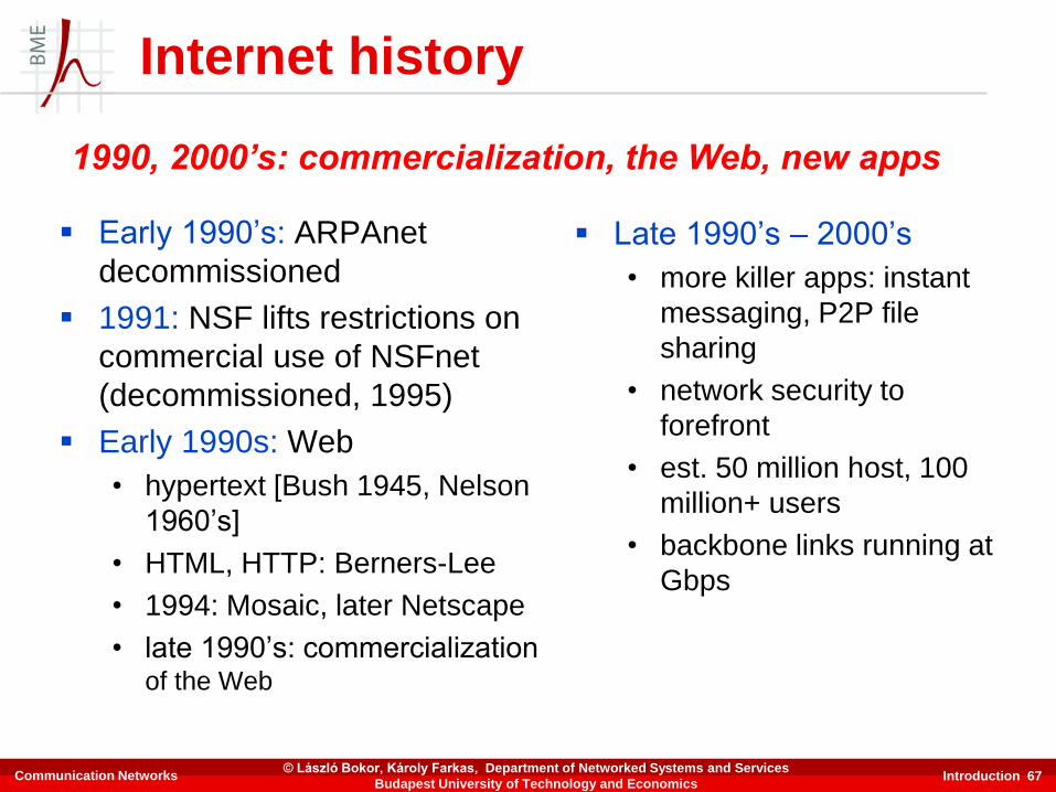
Introduction 67
▪ Early 1990’s: ARPAnet
decommissioned
▪ 1991: NSF lifts restrictions on
commercial use of NSFnet
(decommissioned, 1995)
▪ Early 1990s: Web
• hypertext [Bush 1945, Nelson
1960’s]
• HTML, HTTP: Berners-Lee
• 1994: Mosaic, later Netscape
• late 1990’s: commercializationof the Web
▪ Late 1990’s – 2000’s
• more killer apps: instant
messaging, P2P file
sharing
• network security to
forefront
• est. 50 million host, 100
million+ users
• backbone links running at
Gbps
1990, 2000’s: commercialization, the Web, new apps
Internet history
Communication Networks© László Bokor, Károly Farkas, Department of Networked Systems and Services
Budapest University of Technology and Economics

Internet history
Introduction 68
▪ 2010
• ~750 million hosts
• voice, video over IP
• P2P applications:
BitTorrent (file sharing)
Skype (VoIP), PPLive
(video)
• more applications:
YouTube, gaming, Twitter
• wireless, mobility
Communication Networks© László Bokor, Károly Farkas, Department of Networked Systems and Services
Budapest University of Technology and Economics

Introduction 69
Introduction: Summary
Covered a “ton” of material!
▪ Internet overview
▪ What’s a protocol?
▪ Network edge, core,
access network
• packet-switching versus
circuit-switching
▪ Internet/ISP structure
▪ Performance: loss, delay
▪ Layering and service
models
▪ History
You now have
▪ Context, overview, “feel” of networking
▪ More depth, detail to follow!
Communication Networks© László Bokor, Károly Farkas, Department of Networked Systems and Services
Budapest University of Technology and Economics