chapter 1 introduction -...
TRANSCRIPT

1
CHAPTER 1
INTRODUCTION
1.1 GENERAL
changing market demands. The customer wants a good quality product at a
very competitive price. This forces every production industry to focus on high
changing global scenario on just in time or on time delivery, the
manufacturing systems design has undergone various changes from the
traditional methods. The trend of business is from few models in large
quantity to many models in small quantity in highest order. In this highly
competitive environment, markets are heterogeneous and volatile in nature. A
manufacturing firm to sustain under the volatile demand condition, its
production process has to be configured suitably. The ability to design and
operate manufacturing facilities that can quickly and effectively adapt to
changing technological and marketing requirements is becoming increasingly
important to the success of any manufacturing organization. Hence,
manufacturing facilities must be able to exhibit high levels of flexibility and
robustness despite significant changes in their operating requirement. The
emphasis now is on working closely with customers and suppliers.


4
manufacturing system and then to a job shop ( a process layout). In addition
to these three, there is also another type of layout called as a fixed layout.
Figure 1.1 Classification of Manufacturing systems
The above figure indicates, there is an overlap in the systems
definition. This overlap results because of the difference in investments
possible in different cases and the definition of such systems as desired by the
management of the particular plant. For example though our classification
places a cellular manufacturing system between a job shop and a production
line, it mentions that a group layout has been observed to work quite
efficiently. So the planners of a particular plant might decide to go for a
production line for a product, another might choose to group this product with
others of the same type and form production cells. However in most cases it is
not difficult to make a choice about the type of system to be used.
1.3.1 Group Technology
The main driving force behind manufacturing system is the concept
of Group Technology (GT). GT as the term indicates similar things together.
GT is a method that improves manufacturing efficiency by classifying similar
products into families has been given by Heragu (1994) thus the key concept
Dedicated Line /
Cellular Manufacturing
Systems
Prod
uctio
n V
olum
e
Number of Parts

5
of GT is to plan a total division of parts or products into groups and families,
based on common features shared by all the products considered for
introduction in to the group. These features share similar production processes
or techniques. The main idea behind such a division is to bring similar
products/parts together so that costs resulting out of non-value added process,
costs due to setups, inventory and material handling can be reduced from the
survey of Onyeagoro (1995).
1.3.2 Cellular Manufacturing
Manufacturing industries are under intense pressure from the
increasingly-competitive global marketplace. Shorter product life-cycles,
time-to-market, and diverse customer needs have challenged manufacturers
to improve the efficiency and productivity of their production activities.
Manufacturing systems must be able to output products with low production
costs and high quality as quick as possible in order to deliver the products to
customers on time. In addition, the systems should be able to adjust or
respond quickly to changes in product design and product demand without
major investment. Traditional manufacturing systems, such as job shop and
flow shop lines are not capable of satisfying such requirements.
Job shops are the most common manufacturing system in some
countries. In general, job shops are designed to achieve maximum flexibility
such that a wide variety of products with small lot sizes can be manufactured.
Products manufactured in job shops usually require different operations and
have different operation sequences. Operating time for each operation could
vary significantly has been pointed out by Black (1991). Products are
released to the shops in batches. The requirements of the job shop shows a
variety of products and small lot sizes dictate what types of machines are
needed and how they are grouped and arranged. General-purpose
machines are utilized in job shops because they are capable of performing

6
many different types of operations. Machines are functionally grouped
according to the general type of manufacturing process, lathes in one
department, drill presses in another, and so forth. Figure 1.2 illustrates a job
shop. A job shop layout can also be called as functional layout.
Figure 1.2 Job Shop Manufacturing
In job shops, jobs spend 95% of their time in nonproductive
activity; much of the time is spent for waiting in queue and the remaining
5% is split between lot setup and processing. When the processing of a part
in the job shop has been completed, it usually must be moved a relatively
large distance to reach the next stage. It may have to travel the entire facility
to complete all of the required processes as shown in Figure 1.2. Therefore, to
make processing more economical, parts are moved in batches. Each part in a
batch must wait for the remaining parts in its batch to complete processing
before it is moved to the next stage. This leads to longer production times,

7
high levels of in-process inventory, high production costs and low production
rates.
In contrast to job shops, flow lines are designed to manufacture
high volumes of products with high production rates and low costs. A flow
line is organized according to the sequence of operations required for a
product. Specialized machines, dedicated to the manufacture of the product,
are utilized to achieve high production rates. These machines are usually
expensive; to justify the investment cost of such machines, a large volume of
the product must be produced. A major limitation of flow lines is the lack of
flexibility to produce products for which they are not designed. This is
because specialized machines are setup to perform limited operations and are
not allowed to be reconfigured. Figure 1.3 shows an example of a flow line.
Figure 1.3 Flow Line Manufacturing
production requirements where manufacturing systems are often required to
be reconfigured to respond to changes in product design and demand. The
only solution to face this challenge is Cellular Manufacturing (CM). As a
result CM an application of group technology (GT) has emerged as a
promising alternative manufacturing system. CM involves the formation of

8
part families based upon their similar processing requirements and the
grouping of machines into manufacturing cells to produce the formed part
families. A part family is a collection of parts which are similar either
because of geometric shape and size or similar processing steps required
in their manufacture. A manufacturing cell consists of several functionally
dissimilar machines which are placed in close proximity to one another and
dedicated to the manufacture of a part family.
The theory of CM is to break up a complex manufacturing facility
into several groups of machines called cells. A cell is a group of dissimilar
machines physically located in close proximity, such that a part is processed
from start to finish in a single unidirectional flow (without backtracking) has
been pointed out by Ruiz-Torres and Nakatani (1998). Each being dedicated
to the processing of a part family and is ideally produced in a single cell.
Thus, material flow is simplified and the scheduling task is made much easier.
As reported in the survey by Wemmerlov and Johnson (1997), production
planning and control procedures have been simplified with the use of CM.
The job shop and flow line is converted into a Cellular Manufacturing System
(CMS) as shown in Figure 1.4. Obvious benefits gained from the conversion
of the shop are less travel distance for parts, less space required, and fewer
machines needed. Since similar part types are grouped, this could lead to a
reduction in setup time and allow a quicker response to changing conditions.
On the other hand, in the job shop, each part type may have to travel through
the entire shop; hence scheduling and materials control are difficult. In
addition, job priorities are complex to set and hence large inventories are
needed so as to ensure that ample work is available.

9
Figure 1.4 Cellular Manufacturing.
CM is a hybrid system linking the advantages of both job shops
(flexibility in producing a wide variety of products) and flow lines (efficient
flow and high production rate). In CM, machines are located in close
proximity to one another and dedicated to a part family. This provides the
efficient flow and high production rate similar to a flow line. The use of
general- purpose machines and equipment in CM allows machines to be
changed in order to handle new product designs and product demand with
little efforts in terms of cost and time. So it provides great flexibility in
producing a variety of products.
1.3.2.1 Benefits of CM
The advantages derived from cellular manufacturing in
comparison with traditional manufacturing systems in terms of system
performance has been discussed by Levasseur et al (1995), Singh and
Rajamaani (1996) and Wemmerlov & John (1997). These benefits have been

10
established through simulation studies, analytical studies, surveys, and actual
implementations. They can be summarized as follows:
1. Setup time is reduced. A manufacturing cell is designed to
handle parts having similar shapes and relatively similar sizes.
For this reason, many of the parts can employ the same or
similar holding devices (fixtures). Generic fixtures for the part
family can be developed so that time required for changing
fixtures and tools are decreased, pointed out by Suresh and
Meith (1994).
2. Lot sizes are reduced. Once setup times are greatly reduced in
CM, small lots are possible and economical. Small lots give
smooth production flow has been stated by Singh and
Rajamaani (1996).
3. Work-in-process (WIP) inventories are reduced. With smaller
lot sizes and reduced setup times, the amount of WIP can be
reduced. Askin and Standridge (1993) showed that the WIP
can be reduced by 50% when the setup time is cut in half. In
addition to reduced setup times and WIP inventory, finished
goods inventory is reduced. Instead of make-to-stock systems
with parts either being run at long, fixed intervals or
random intervals, the parts can be produced either just-in-
time (JIT) in small lots or at fixed, short intervals.
4. Material handling costs and time are reduced. In CM, each
part is processed completely within a single cell (where
possible). Thus, part travel time and distance between cells is
minimal.

11
5. A reduction in flow time is obtained. Reduced material
handling time and reduced setup time greatly reduce the flow
time has been pointed out in the literature of Shafer and
Charnes (1994)
6. Tool requirements are reduced. Parts produced in a cell are of
similar shape, size, and composition. Thus, they often have
similar tooling requirements.
7. A reduction in space required. Reductions in WIP, finished
goods inventories, and lot sizes lead to less space requirement
has been pointed out by Singh and Rajamaani (1996).
8. Throughput times are reduced. In a job shop, parts are transfer
between machines in batches. However, in CM each part is
transfer immediately to the next machine after it has been
processed. Thus, the waiting time is reduced substantially
rightly pointed out by Singh and Rajamaani (1996).
9. Product quality is improved. Since parts travel from one
station to other as single units, they are completely processed
in a small area. The feedback is immediate and the process
can be stopped when things go wrong.
10. Better overall control of operations. In a job shop, parts may
have to travel through the entire shop. Scheduling and
material control are complicated. In CM, the manufacturing
facility is broken down into manufacturing cells and each part
travels with a single cell, resulting in good scheduling and
control.

12
1.3.2.2 Design of CM
As described above, the benefits resulting from CM can be
substantial. Getting CM in place, however, is not a simple task. Design of
cellular manufacturing systems (CMS) is a complex, multi-criteria and multi-
step process. Ballakur showed that this problem, even under fairly restrictive
conditions, is NP-complete. The design of CMSs has been called cell
formation, part family/machine cell formation, and manufacturing cell design.
Given a set of part types, processing requirements, part type demand and
available resources (machines, equipment, etc.,), the design of CMS consists
of the following three key steps:
1. Part families are formed according to their processing
requirements.
2. Machines are grouped into manufacturing cells.
3. Part families are assigned to cells.
Note that these three steps are not necessarily performed in the
above order, or even sequentially. Part families and manufacturing cells can
be formed simultaneously, along with the assignment of part families to the
cells. After the design steps have been completed, a manufacturing cell
configuration for shortest route is obtained. It is refer to as a cellular
manufacturing system (CMS) which consists of a set of manufacturing cells;
each cell is constituted of a group of machines and is dedicated to produce a
part family. The layout or arrangement of machines in each cell belongs to the
layout design problem, and is also considered in this research.
The author suggested three solution strategies based on the
procedure used to form part families and manufacturing cells. They can be
used as a framework to classify existing CM design methods. The three
solution strategies are as follows:

13
1. Part families are formed first, and then machines are grouped
into cells according to the part families. This is called the part
family grouping solution strategy.
2. Manufacturing cells are created first based on similarity in
part routings, and then the parts are allocated to the cells. This
is referring to as the machine grouping solution strategy.
3. Part families and manufacturing cells are formed
simultaneously. This is the simultaneous machine part
grouping solution strategy.
On the whole for the design of CMS, the design objective must be
specified. Minimizing intercellular moves, distances, costs, and the number
of exceptional parts (parts that need more than one cell for processing) are
common design objectives. An exceptional part can be also called an
exceptional element or a bottleneck part. In addition to the design objectives,
some of strategic issues such as machine flexibility, cell layout, machine
types, etc., need to be considered as a part of the CM design problem. Further,
any cell configuration should satisfy operational goals (constraints) such as
desired machine utilization, production volume, number of manufacturing
cells, cell sizes, etc. The followings are typical design constraints in the
design of CMS.
1. Machine capacity. It is obvious that, in the design of
CMS, one of the basic requirements is that there should be
adequate capacity to process all the parts.
2. Cell size. The size of a cell, as measured by the number of
machines in the cell, needs to be controlled for several
reasons. First, available space might impose limits on the
number of machines in a cell. If a cell is run by operators, the

14
size of the cell should not be so large that it hinders visible
control of the cell. Ranges of cell sizes can be specified
instead of a single value of cell size. This would allow more
flexibility in the design process.
3. Number of cells. In practice, the number of cells would be set
by organizational parameters such as the size of worker
teams, span of supervisory authority, and group dynamics has
been given by Askin et al (1997). Given a range of cell
sizes, the number of cells are determined and the resultant
solutions can be compared.
4. Utilization levels. Two levels of machine utilization are
normally used. Maximum utilization is specified to ensure
that machines are not overloaded. Minimum utilization for a
new machine ensures that it is economically justifiable to
include the new machine in a cell.
1.3.3 Lean Manufacturing
production control on an individual part basis. Under single piece flow parts
will be produced at a rate set by the Takt time. This will create a
synchronized flow of product and essentially form a linkage between cells.
The production system will be transformed into a set of linked cells. The
Takt time is the length of time required between successive units of end
product, and is determined by the following equation
Takt Time =
15
In short, the factory must produce a part once in every X seconds,
where X = Takt time. The manufacturing lead time and order lead time will
be reduced by converting the factory from a job shop to cellular
manufacturing. This transition to cellular manufacturing will be accompanied
by implementation of improved quality methods, including the transition from
final inspection to successive inspections to self checks and finally to
installation of Poka-Yoke devices. Most disturbances caused by unplanned
machine downtime will be eliminated through implementation of Lean
principles. We will create an accurate flow of information by eliminating the
forecaster. Since forecasting is essentially guesswork, the optimal value for
the forecasting factor is 0 . In this case, the required quantity will be passed
directly to the supplier.
of goods through the factory. The
customer.
The length of time between productions of successive parts to meet a demand
is called the Takt time. We must establish a preset or refined inventory
quantity which will replace the inventory controller by creating a flow of
information which flows in the opposite direction of the material flow and
sets the total quantity of parts that can be in inventory at any given time. In
essence we are specifying a fixed and controlled quantity of inventory, rather
than allowing it to fluctuate as was the case in the traditional manufacturing
system. Having a fixed quantity of inventory in the factory will eliminate the
amplification due to variability in customer demand. Incoming orders are now
received by the shipper who begins removing finished goods from the
shipping area at a rate equal to the Takt time. The Takt time is the rate at
which the shipper must pull a single part in order to fill the order for the day.
The factory in turn pulls raw material from the raw material bins and

16
produces parts at the rate that the shipper is pulling finished goods. Finally,
the material planner multiplies the Takt time by the reorder quantity and
determines the frequency that shipments must be received from the supplier.
This system is considerably simpler. Information transfer in the form of the
shipper removing product now forms the feedback for the control loop. The
factory is not instructed to produce a certain quantity of goods, but rather to
produce at a certain rate, as they are pulled to be shipped. By reversing the
(at a frequency set by the Takt time) signals the system to begin production.
1.3.4 Flexible Manufacturing Systems
Flexible manufacturing systems (FMS) are distinguished by the use
of computer control in place of the hard automation usually found in transfer
lines. The high investment required for a FMS and the potential of FMS as a
strategic competitive tool make it attractive to engage in manufacturing
research area. Articles emphasizing many methodological perspectives are
critically reviewed from multiple viewpoints. FMS are distinguished by the
use of computer control in place of the hard automation usually found in
transfer lines. This enables FMS's to reconfigure very rapidly to produce
multiple part types. Use of fixtures and tool magazines practically eliminates
setup time. These features permit economic production of a large variety of
parts in low volumes. FMS's are increasingly being adopted in the
manufacturing sector on account of the additional advantages of rapid
turnaround, high quality, low inventory costs, and low labour costs. The high
investment required for a FMS and the potential of FMS as a strategic
competitive tool make it attractive to engage in research areas. The research
problems raised by the industrial support of FMS could be broadly classified
into two areas: design problems and operation problems. At the design stage,

17
one is interested in specifying the system so that the desired performance
goals are achieved. The operation problems are aimed at making decisions
related to the planning, scheduling, and control of a given FMS.
1.3.5 Nagare Cell Manufacturing
Nagare cell is a Japanese concept based on single product flow and
the U shaped layout of the cells in which the operators walk around the cell
performing various actions including material handling from raw materials to
the finished goods. Nagare Cell is a natural group of machines, men and parts
manufactured in it, where men move from machine to machine carrying work
piece with them. Nagare cell manufacturing (NCM) is a series of techniques
for identifying and eliminating inventory by continuously improving the flow
of product at the pull of the customers has been pointed out by Brooks and
Duffill (1992). This system satisfies the customers on delivery, quality and
price. The basic goal is to get more work done with fewer resources and
results in dramatic reduction of cycle times, faster customer responsiveness,
increased employee productivity and higher equipment utilization. Space
requirements, scrap and rework are also reduced. In addition Nagare cell is
also a Just in time manufacturing approach used to achieve the excellence in a
manufacturing based on the continuous elimination of waste and consistent
improvement in productivity. It provides the cost of effective production and
delivery of only the necessary quality parts, in the right quantity at the right
time.
1.4 JUST IN TIME
JIT is an action program to continuously and simultaneously work
towards excellence in manufacturing by eliminating waste. Dimensions of
excellence are

18
zero defects
zero customer lead time
zero inventory
zero down time.
The dimension of waste is anything other than the minimum
amount of resource which is absolutely essential to add value to the product.
Resources include materials, space, labour (works, staff and executive), cash,
cit, machines and energy. Simplification of the enterprise objectives can help
us to make the choice
To make money
With excellence
By eliminate waste
Significant small changes can be started with a low-cost option of
welfare: a cleaner factory, better tool storage, revised plant layout, shorter
lead time, reducing inventory levels, cutting lead times, reducing batch size to
providing product quality and adopting a more responsive attitude to the
customer are all now paramount. This has only been achieved by
communication, technical ability and commitment from its entire workforce,
aided by externally driven training programs. The need to compete on all
these fronts without major capital outlay has shown improved company
performance over consecutive years, with the ability to stay ahead of
competition. The introduction of new manufacturing practice has improved
output and quality; the respective cell managers are now directly responsible
for customer targets within agreed budget guidelines. This has encouraged
flexible working by its operatives. From a managerial point of view, the
ability to accept change is a priority. The examination of the present

19
performance by the competitors can identify strengths and weaknesses for
attention. Marketing, manufacturing and ongoing training reconcile the needs
of customers, employees and the firm.
1.5 SEQUENCING AND SCHEDULING
Sequencing is a technique to order the jobs in a particular sequence.
There are different types of sequencing which are followed in industries such
as first in first out basis, priority basis, job size basis and processing time
basis etc. In processing time basis sequencing for different sequence, will
achieve different processing time. The sequence is adapted which gives
minimum processing time. By Scheduling, one can assign a particular time
for completing a particular job. The main objective of scheduling is to arrive
at a position of getting minimum processing time. Pinedo (2005)
demonstrated the information flow for a manufacturing system is shown in
Figure 1.5. In a manufacturing environment, the scheduling function has to
interact with other decision making functions. After a schedule has been
generated it is necessary that all raw materials and resources are available at
the specified times.

20
Figure 1.5 Information flow diagram for a manufacturing system.
1.5.1 Types of Scheduling
The processing of n jobs with m operations on each of the machine
is flow shop scheduling. Basically there are three types of scheduling, they are

21
Single Machine Scheduling - The processing of n jobs with the
same single operation on each of the jobs is called as single
machine scheduling.
Flow Shop Scheduling There are n jobs, each requires
processing on m different machines. The order in which the
machines are required to process a job is called process
sequence. This type of scheduling is flow shop scheduling.
Job Shop Scheduling Each job has m different operations, if
some of the jobs are having less than m operations, the required
number of dummy operations with zero process times are
assumed.
This Venn diagram can show the relative sizes between different
types of schedules as shown in the Figure 1.6 there will be at least one
optimal schedule in the set of active schedules.
Figure 1.6 Venn diagram showing different schedules
Semi active Schedules
Non Delay Schedules
22
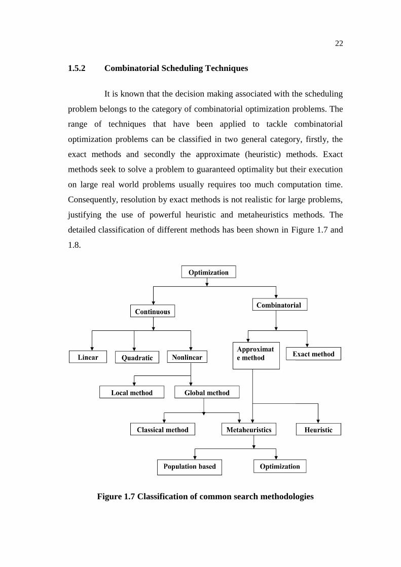
1.5.2 Combinatorial Scheduling Techniques
It is known that the decision making associated with the scheduling
problem belongs to the category of combinatorial optimization problems. The
range of techniques that have been applied to tackle combinatorial
optimization problems can be classified in two general category, firstly, the
exact methods and secondly the approximate (heuristic) methods. Exact
methods seek to solve a problem to guaranteed optimality but their execution
on large real world problems usually requires too much computation time.
Consequently, resolution by exact methods is not realistic for large problems,
justifying the use of powerful heuristic and metaheuristics methods. The
detailed classification of different methods has been shown in Figure 1.7 and
1.8.
Figure 1.7 Classification of common search methodologies

23
Figure 1.8 Classification of common metaheuristics.
1.5.3 Plant Layout
Layout pattern determines the placement of departments, work
groups within the departments, workstations, machines, and stock-holding
points within a production facility are very important for effective working
environment. The objective is to arrange the various departments in a way
that ensures a smooth work flow (in a factory) or a particular traffic pattern
(in a service organization). In general, the inputs to the layout decision are as
follows,
1. Specification of the objectives and corresponding criteria to
be used to evaluate the design, the amount of space required,
and the distance be traveled between elements in the layout,
are common the basic criteria.

24
2. The estimate of product or service demand for the system.
3. The processing requirements in terms of number of operations
and amount of flow between the elements in the layout.
4. The space requirements for the elements in the layout.
5. The space availability within the facility itself, or if this is a
new facility, possible building configurations.
The emphasis is on quantitative techniques, but also with examples
of how qualitative factors are important in the design of the layout for both
manufacturing and service facilities.
1.5.4 Layout Formats
The formats by which departments are arranged in a facility are
defined by three basic types (process layout, product layout, and fixed-
position layout) and one hybrid type (group technology or cellular layout).
i) A process layout (also called a job-shop or functional layout)
is a format in which similar equipment or functions are
grouped together, such as all lathes in one area and all
stamping machines in another. A part being worked on then
travels, according to the established sequence of operations,
from area to area, where the proper machines are located for
each operation. This type of layout is typical of hospitals, for
example, where areas are dedicated to particular types of
medical care, such as maternity wards and intensive care
units.
ii) A product layout (also called a flow-shop layout) is one in
which equipment or work processes are arranged according to

25
the progressive steps by which the product is made. The path
for each part is, in effect, a straight line. Production lines for
shoes, chemical plants, and car washes are all product layouts.
iii) In a fixed-position layout, the product (by virtue of its bulk
or weight) remains at one location. Manufacturing equipment
is moved to the product rather than vice versa. Construction
sites and movie lots are examples of this format. Many
manufacturing facilities present a combination of two layout
types. For example, a given production area may be laid out
by process, while another area may be laid out by product. It
is also common to find an entire plant arranged according to
product layout for example, a parts fabrication area followed
by a subassembly area, with a final assembly area at the end
of the process. Different types of layouts may be used in each
area, with a process layout used in fabrication, group
technology in subassembly, and a product layout used in final
assembly.
iv) A group technology (cellular) layout groups dissimilar
machines into work centers (or cells) to work on products that
have similar shapes and processing requirements. A GT
layout is similar to a process layout in that cells are designed
to perform a specific set of processes, and it is similar to a
product layout in that the cells are dedicated to a limited range
of products. (Group technology also refers to the parts
classification and coding system used to specify machine
types that go into a cell.)
v) U shaped cell the most sensible organizing cell layout
preferable for effective utilization is a U shaped layout.

26
This is product flow oriented and operators become capable of
handling multiple processes. Also enable operators to produce
and transfer parts (single piece at a time). It minimizes the
operators walking time and walking distances. It rectifies the
additional space required to accumulate the in process
inventory, unnecessary handling of materials, slow feedback
of quality information and longer production lead time.
1.6 SIMULATION
One of the gurus of simulation so called Robert E. Shannon (1975)
historically defined simul e process of designing a model for a real
or imaginary system and conducting experiments with that model for the
purpose of either understanding the behavior of the system or for evaluating
various strategies (within the limits imposed by a criterion or set of criteria)
general framework of simulation principles and gives a clue of the roadmap
that simulation has gone through within the last century. Each and every word
can phrase the definition emphasized the exact comprehension of the term
simulation. The first sentence of the definition mentions the types of systems
here can exist a physical facility or a process
to be modeled, or the model can be a modification of the existing system or it
can be totally imaginary. The imaginary systems refer to the ones that are
planned as alternatives to existing systems or for entirely the original systems.
1.6.1 Simulation Process
S onetime create-
and-use application. Especially computer simulation is an iterative method
that includes several stages has been identified by Kelton et al (2004). A
27
simulation study starts with efforts on understanding the system in addition
with the identification of the goals of the study. Then create the formulation
of the represented model usually in terms of mathematical models or
flowcharts. Subsequently, the created formulation needs to be transfer into
modeling software using programming languages or with specific software
tailored into the needs of a simulation study. Once a program is created, it is
necessary to verify the program, in the sense that the right things occur with
expected inputs. The following stage is to validate the program with someone
familiar to the represented system so that the program works in accordance
with the conceptual model faithfully, supporting the validation work with
statistical tests can be of critical importance at this stage. Experimentation on
the developed model is the following phase, which includes designing
experiments to identify the critical performance measures to be used with
adequate confidence and running these designed experiments by using the
computers effectively. The last stages take account of analyzing the results,
getting insight of the results to evaluate the outcomes of the results and to
assess the potential benefits. Finally, documentation is necessary for the
inheritance of the work done for other simulation staff and also to clearly
transfer the findings and recommendations to related management levels with
precision and confidence.
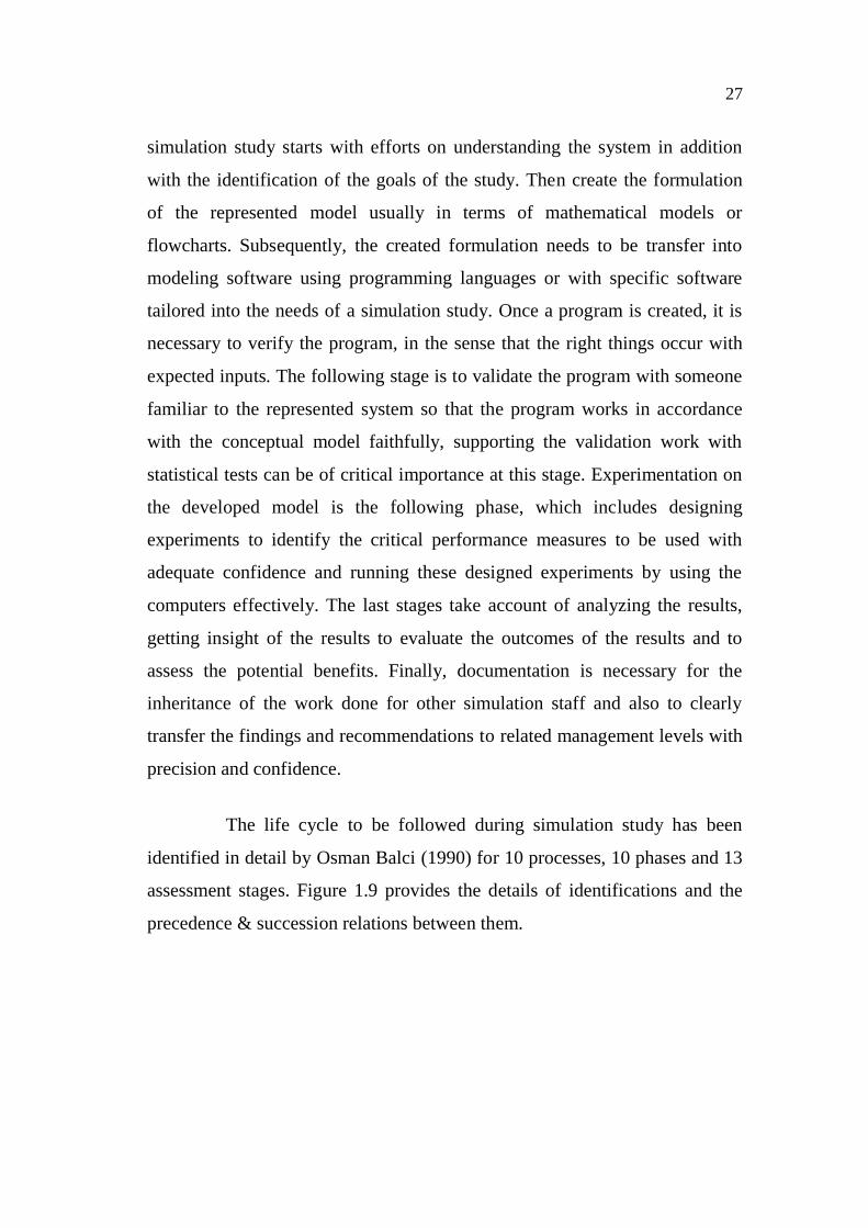
The life cycle to be followed during simulation study has been
identified in detail by Osman Balci (1990) for 10 processes, 10 phases and 13
assessment stages. Figure 1.9 provides the details of identifications and the
precedence & succession relations between them.

28
Figure 1.9 The life cycle of simulation study
All those steps mentioned in the Figure 1.9 seems troublesome and
time consuming, however success in simulation is difficult to attain without
following these steps. It is necessary to identify what success is at this stage.
According to Sadowski (1997), a successful simulation project is the one that
delivers useful information at the appropriate time to support a meaningful
decision, which implies that decision, timing and information are the three
key elements to be assessed to get success in simulation.

29
1.6.2 Simulation Benefits
Simulation has many benefits for the users. First of all, the users
can choose correctly the possible alternatives, provides time compression and
expansion according to the type of the simulated event, equips the managers
with the tools to understand certain phenomena occur in a real system and
allows the user to explore possibilities of new policies, operating procedures
or methods. With simulation, one can diagnose problems of complex systems
that are almost impossible to deal within the real environment, identify
constraints that act as a bottleneck for operations, visualize the plan using the
animation capabilities of the software used that results in a more presentable
design. Simulation is also beneficial to build consensus among the members
of the decision makers and to prepare for changes by considering the possible
reality support creates training environments for
production team, it can also be used to specify requirements for capabilities of
equipment and carry out wise investments using all those properties. In
accordance with this definition and benefits, simulation has been extensively
used as an off-line decision making tool for helping the management with
production planning issues such as efficient capacity utilization, sequencing
and scheduling and allocation of resources in manufacturing and production.
1.7 RESEARCH OBJECTIVES
A new scheduling and simulation strategy to address the problem
statement i.e. the objectives of this research are summarized as follows
1. To develop a design methodology for NCM systems in
dynamic and stochastic production environments which
employ system reconfigurations and routing flexibility?
30
2. To justify the NCM design methodology via experimental
problems and compare with known solutions.
3. To identify the optimal schedule by SPT algorithm and
simulating the model.
1.8 RESEARCH APPROACH
To achieve the development of NCM design methodology, the
research approach consists of the following steps
1. Designing a NCM problem for dynamic production
requirements.
2. Evaluate the potential benefits gained through the
consideration of system dependent reconfiguration and
routing flexibility.
3. Generate problem instances to be used for validating the
developed design. Incorporate uncertain production
requirements into the developed design.
4. Develop and validate a heuristic approach for dynamic and
uncertain production requirements due to the computational
time required for large problems.
5. Evaluating experimental design to compare performance of
heuristic versus optimal and vs. other heuristics.
6. Developing the logic for simulation and run the simulation by
packages.
7. Discussing the results and the output of the problems solved.
31
8. Summarize the conclusions and discussing the directions for
future work.
1.9 OUTLINE OF THESIS
This dissertation or the progress work is organized as follows.
Chapter 2 presents the previous literature reviews which helps in defining and
solving the design of Cellular manufacturing system, its scheduling phase and
its simulation phase of this work. Chapter 3 contains the problem statement of
this thesis. Chapter 4
i.e. Cellular manufacturing to Nagare cell. Chapter 5 covers the CM layout
and its advantages. Chapter 6 explains the first phase of the work i.e Nagare
Cell Manufacturing i.e. design & its evaluation phase. In Chapter 7 the
methods used for scheduling NCM and evaluation methodology with new
modified algorithm heuristic is presented. Chapter 8 presents the NCM
simulation and the methods applied in this work with the results from the
evaluation. Finally Chapter 9 gives conclusions, contributions, and the future
research of this work.