chapter 06 - wood pole conductor erection
TRANSCRIPT

WP Ref.: 420\Part_1\CHAP06.doc 27.09.97 DPH Issue 2 Page 1 © 2010 Electricity North West Limited.
CHAPTER 06 - WOOD POLE CONDUCTOR ERECTION
1. INTRODUCTION
2. REFERENCES
3. TOOLS, EQUIPMENT AND MOBILE PLANT
4. WORK PLANNING
5. CONDUCTOR ERECTION PROCEDURE
5.1 Safety Precautions
5.1.1 Working Procedures 5.1.2 Climbing Poles 5.1.3 Safe Working Distance 5.1.4 Running Out or Lowering of Overhead Conductors
5.2 Erecting Temporary Stays 5.3 Preparation Prior to Conductor Erection 5.4 Running Out Conductor 5.5 Tensioning of Conductors 5.6 Site Clearance
6. RE-STRINGING CONDUCTORS
7. WORKING PROCEDURES
8. ASSOCIATED DRAWINGS
WP Ref.: 420\Part_1\CHAP06.doc 27.09.97 DPH Issue 2 Page 2 © 2010 Electricity North West Limited.
1. INTRODUCTION
1.1 This chapter details essential precautions to be taken and the procedures used during conductor erection on wood pole overhead lines. Mural Wiring Mains are detailed in Chapter 23 and Aerial Bundled Conductors are detailed in Chapter 24 of this Code of Practice. All other types of conductor currently in use by Electricity North West are covered by these procedures. It gives guidance on the methods and practices which should be employed for running out, sagging and tensioning of conductors supported on wood poles.
1.2 The main elements of conductor erection on wood poles are:
(i) Work planning.
(ii) Running out.
(iii) Pulling up, Sagging/tensioning.
(iv) Making Off.
1.3 It is not possible to define a single method which will be practical in all circumstances and therefore this document covers those essential items which must be taken into account in any conductor erection work. Separate sections detail the procedures to be followed when removing and/or restringing conductors.
1.4 Prior to any work being carried out the person in charge on site will ensure that everyone in the working party should be fully acquainted with the procedures to be adopted in order to ensure the safety of Electricity North West personnel, the public and livestock, especially when erecting conductors over roads, public footpaths, pasture fields etc. Approved procedures and equipment must be used.
2. REFERENCES
2.1 In the preparation of this document, reference has been made to the following:
(i) Electricity North West COP 605.
(ii) Electricity North West COP 606.
(iii) Electricity North West Safety Rules.
(iv) GS 6.
2.2 All completed work must meet the Design Requirements of Electrical Association Technical Specification (EATS) 43-10, 43-20, 43-30, 43-92, Electricity North West's Codes of Practice and agreements with other public bodies.
2.3 Using EATS 43-92 and Code of Practice 50, correct joints are to be selected for the conductors, joints to be made as laid down by Electricity North West/manufacturers instructions and Bi-metallic joints to be positioned and protected as specified.
3. TOOLS, EQUIPMENT AND MOBILE PLANT
The tools and equipment required for the erection of overhead line conductors on wood poles are described in Chapters 11, 12 and 14 covering Personal, Team and Mobile Equipment and the person in charge will ensure that the appropriate equipment is available.

WP Ref.: 420\Part_1\CHAP06.doc 27.09.97 DPH Issue 2 Page 3 © 2010 Electricity North West Limited.
4. WORK PLANNING
4.1 Preparation of the site is fundamental to a smooth and safe operation. Many site-related factors will influence the choice of working methods and therefore a site inspection must be carried out. The purpose of this is to identify hazards and problems which may require further consideration. It is not possible in this document to list every conceivable situation which must be investigated but the following is a minimum checklist:
(i) Type of terrain
(ii) Ground conditions
(iii) Wayleave constraints
(iv) Access difficulties
(v) Physical obstructions
(vi) Proximity of structures
(vii) Proximity of other overhead lines
(viii) Road, rail, river etc. crossing points.
4.2 The drawings shown in Section 7 show the different types of terrain that may be met whilst working in the Electricity North West area and the different considerations that must be taken into account before erecting conductors in one of these areas.
4.3 After the physical characteristics of the site have been assessed, the manpower and material requirements can be determined. This will cover such items as:
(i) Number, size and type of conductors and length of line to be erected. This will have a bearing on the manpower required and the length of any outage which may be required.
(ii) The most suitable vehicles to cope with the ground conditions and minimise land damage.
(iii) Any specialist work which must be arranged in advance of the outage e.g. erection of scaffolding, attendance by BR flagmen, temporary diversion of BT lines.
(iv) Any special vehicles and/or mobile plant which have to be hired or brought from another Electricity North West department.
(v) Availability of manpower, plant and equipment.
4.4 Whenever an overhead line is to be erected over or under an existing line then the instructions laid down in Electricity North West Code of Practice 606 - Procedure A9 must be followed.
4.5 There are few occasions when conductors have to be erected over existing live line. Most involve tower lines crossing over British Rail electrified systems where an extended outage is not possible. In these circumstances, and with relatively short outages, a "Live Line Scaffold/Net" is built, over which the conductors are pulled. A similar situation with a wood pole line is less likely to arise but if it does the requirements of tower lines as above should be adhered to. Similar procedures must be adopted for road and waterway crossings.
WP Ref.: 420\Part_1\CHAP06.doc 27.09.97 DPH Issue 2 Page 4 © 2010 Electricity North West Limited.
4.6 In instances where tree clearance may be necessary, then a Tree Clearance Schedule shall be agreed with the Contractor appointed for this task.
4.7 A plan for implementing GS6 safety recommendations and Electricity North West Safety Rules in respect of adjacent circuits must be prepared.
4.8 In all situations were conductor erection is taking place the requirements of the wayleave agreement must be strictly adhered to. Liaison with landowners before access is gained is essential.
5. CONDUCTOR ERECTION PROCEDURE
5.1 Safety Precautions
5.1.1 Working procedures
Prior to moving onto site set up the GS6 requirements as contained in the Work Plan.
5.1.2 Climbing poles
Before any pole is climbed it must be tested in an Approved manner. No pole that is badly impaired by decay or damage or whose stability is in doubt has to be climbed until it has been supported by Approved means. Procedures for climbing poles and the safety precautions to be taken are contained in Chapter 5 of the manual and must be adhered to.
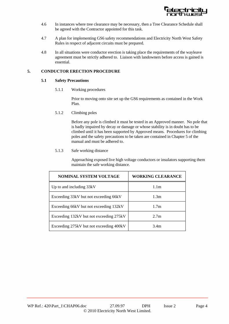
5.1.3 Safe working distance
Approaching exposed live high voltage conductors or insulators supporting them maintain the safe working distance.
NOMINAL SYSTEM VOLTAGE WORKING CLEARANCE
Up to and including 33kV 1.1m
Exceeding 33kV but not exceeding 66kV 1.3m
Exceeding 66kV but not exceeding 132kV 1.7m
Exceeding 132kV but not exceeding 275kV 2.7m
Exceeding 275kV but not exceeding 400kV 3.4m

WP Ref.: 420\Part_1\CHAP06.doc 27.09.97 DPH Issue 2 Page 5 © 2010 Electricity North West Limited.
5.1.4 Running out or lowering of overhead conductors
When any overhead line Conductor is to be raised or lowered or otherwise held on temporary supports/connections. Approved Procedures shall be followed to ensure that no danger is caused at locations such as road/railway crossings etc. where other persons may be present.
No overhead line shall be erected or dismantled without the specific authority of a Senior Authorised Person. Any overhead line over or under which a new overhead conductor is to be run or an existing conductor is to be removed, must either be made dead or adequate precautions are to be taken to prevent danger during the lowering and removal of the existing conductor and the new running out and permanent securing of the new conductor. When a high voltage line has been made dead the requirements of Electricity North West 's Distribution Safety Rules will apply.
5.2 Erecting Temporary Stays
5.2.1 During the running out and tensioning procedures of conductor erection the poles may shift from their plumb position. For this reason temporary stays should be erected at the section and angle poles, in the direction of the next section to be run out.
5.2.2 Temporary stays should be slung in a manner that will ensure the pole remains plumb when the conductors are tensioned.
5.2.3 Temporary stays on section pole must only be erected using approved equipment e.g. slings, bonds, Tirfors, shackles and ground anchor/s.
The Safe Working Load (SWL) and type of equipment will depend on the pole top load to be restrained and this is dependant on the Maximum Working Tension of the conductors.
For safe working the ground anchor/s employed shall be proof loaded, at 1.25 x Load (on backstays) before the stays are installed.
Where stays are to be left on site at the end of a working day, Tirfors etc. shall be "locked off" with bulldog clips to avoid vandalism or public tampering.
Permanent stay (such as on section/angle poles) shall be retained, until all conductors have been lowered, this will increase the angle/area the backstays may fall within.
Temporary stays may also be necessary to provide a secondary "catch off", on road rail crossings etc. (Electricity North West Safety Rule 5.10.7 refers.)

WP Ref.: 420\Part_1\CHAP06.doc 27.09.97 DPH Issue 2 Page 6 © 2010 Electricity North West Limited.
Table 1 List of SWL of Backstays, Anchors etc.
SWL Proof Load
Excavated Stay Block 4000kg 5000kg
Molex 1500 x 300 1800kg 2250kg
Molex 750 x 150 550kg 680kg
K & K Porcupine (Included to line of pull) 725kg 900kg
Ground Stakes (75 x 75 x 1050) 275kg 340kg
Load Locked Anchor (Duckbill) 2700kg 3400kg
AB Chance Augered Stay - As per load indicator less 20% upto 5 tonne.
All above figures refer to normal ground conditions.
Table 2 Average conductor tensions (design at 0°C)
taken from EATS43-40 (most onerous) except where stated.
16mm2 Cu 142kgf
32mm2 Cu 359kgf
70mm2 Cu 965kgf
50mm2 HD AL 268kgf (EATS43-30)
100mm2 HD AL 376kgf (EATS43-30)
50mm2 AAAC 379kgf
100mm2 AAAC 752kgf
175mm2 AAAC 1329kgf
175mm2 ACSR (18/1) 939kgf
175mm2 ACSR (30/7) 1160kgf
Figures given are for each conductor. If three phase, line backstay must have sufficient SWL for "Above Figures x 3 x Multiplying Factor" dependant on stay slope.

WP Ref.: 420\Part_1\CHAP06.doc 27.09.97 DPH Issue 2 Page 7 © 2010 Electricity North West Limited.
When the angle between the pole and the stay equals:-
45 deg - multiplying factor = 1.4
50 deg - multiplying factor = 1.3
55 deg - multiplying factor = 1.2
60 deg - multiplying factor = 1.1
65 deg - multiplying factor = 1.1
Note: 65 deg is approximately equal to a slope of 1:2
Example:
3 Phase ACSR 175mm2 18/1 Caracal conductors
939kgf @ 0°C x 3 conductors = 2817kgf
For a Stay Slope of 60° - Tension in stays = 3099kgf
For a Stay Slope of 45° - Tension in stays = 3944kgf (at 45° the tension of nearly 4 Tonne may have to be shared by 3 Stays in order not to overload the crossarms.
Note: Erection tensions are considerably higher.
5.3 Preparation Prior to Conductor Erection
5.3.1 An inspection of the section of the conductor to be erected must be made to confirm that the following items are in order:
(a) All agreed wayleave and access conditions are being followed.
(b) All poles (including steelwork and insulators) have been erected.
(c) Drum positions and direction of pulling out conductors are satisfactory. The contours of the site will largely determine which method is chosen for running out the conductors. Section 7 illustrates a number of scenarios. These figures (or a combination thereof) cover most of the basic terrain conditions and give guidance on drum positioning and the direction of running out.
(d) All permanent and temporary stays have been installed.
(e) Specific written instructions (approved by the Supervisor) are to hand for any crossings which involve other overhead lines, road, waterways, railways etc.
5.3.2 Provision must be made for each obstruction. The crossing or encroachment of any obstruction must be fully investigated and assessed before any work commences.
(a) Roads - The type of road and usage will dictate the amount of Traffic Management necessary, it will possibly involve notifying the Local Authorities and maybe Traffic Police. The NRSWA must be complied with.

WP Ref.: 420\Part_1\CHAP06.doc 27.09.97 DPH Issue 2 Page 8 © 2010 Electricity North West Limited.
(b) Tracks/Footpaths - Usage will dictate the amount of protection necessary. If the track is subject to heavy usage then other approved means must be adopted to maintain the public thoroughfare.
(c) Railways - The Railway Owner/Controller (i.e. Railtrack) must be contacted and will provide information on line possession times, standby personnel, access permits etc., also requirements for safe crossing of electrified lines and live tracks.
(d) Canals - British Waterways must be contacted to arrange control of Canal Traffic and general access.
(e) Rivers - Rivers are generally control by the Environmental Agency. The Environmental Agency are not overly concerned by overhead line work, though it must be noted that large rivers may be used for water activities (i.e. canoeing). Therefore, it may be necessary to contact the Environmental Agency to make them aware of Electricity North West's intentions.
(f) Telephone Cables - These must be protected by an approved means to avoid damage.
(g) Overhead Conductors - Conductors running under the line to be dismantled must be made dead and earthed in accordance with Electricity North West Safety Rules before any work commences.
Conductors oversailing the line must be checked for sufficient clearance, if they are to remain energised during the dismantling process.
Notes: Extra consideration must be observed where line uplift could cause encroachment of the appropriate safety clearance. (Electricity North West Safety Rules and COP 606 Procedure A9 refer.)
Conductors running adjacent to the line to be dismantled, must have a clearance distance sufficient to eliminate danger. Allowing for the poor condition a line may reach before dismantling, a distance as stated in HSE Guidance Note GS6 (9m - up to 33kV) should be adopted. This will provide sufficient clearance for safe operation taking into account broken wire conditions, heavy line deviations, etc. If sufficient distance cannot be achieved, then an alternative means of control must be agreed with the Senior Authorised Person (SAP) in charge of the work, or the line made dead and earthed in accordance with Electricity North West Safety Rules.
(h) Buildings/Structures - These must be protected to avoid damage.
(i) Fences - These may require protecting in cases where joints/connectors may snag and cause damage during lowering, extra consideration is necessary for the crossing of electric fences and arrangements will be needed to make the fence line dead.
(j) Livestock - Arrangements must be made to pen the livestock at a safe distance away from the work area.

WP Ref.: 420\Part_1\CHAP06.doc 27.09.97 DPH Issue 2 Page 9 © 2010 Electricity North West Limited.
(k) Special Permission Sites - These may be sites such as Chemical Industry, M.o.D. Land, Nuclear Fuel Plants etc. All work in these areas will require clearance/approval before work may commence.
Notes: Access clearance will need to be noted detailing access for walking or vehicles. This information will need to be forwarded to the Estates and Wayleave Department, with the necessary "Request for Wayleaves" form. It is important to take into consideration the amount of time required to arrange access on a long length of line, or in a section that runs through a particularly sensitive area.
For all Public Areas the necessary (public awareness) warning signs must be erected whilst work is in progress.
Personnel must be posted, with adequate communication, within close proximity of all problem areas whilst lowering or drum winding of conductors.
When dismantling protection or traffic stoppage is only needed for short periods of time. Once the conductors have been lowered and the tension released, they can be immediately cut away to free the problem area.
5.3.3 Position cable drums as follows:
(a) Position drums at the required terminal or section point, ensuring drums are cleared of all loose nails, staples and broken timber etc.
(b) An experienced person should always be in charge of the drums while conductors are being run out. The drums must be in line and braked to ensure that they do not over run and permit kinking of the conductor.
(c) Running Earths should be positioned as required, primarily on the drum end. The earth lead from the running earths should be taken to a common earth spike.
5.3.4 Prepare pole as follows:
(a) Plumb section and terminal poles.
(b) Having ensured that the route is clear for the running out of the conductors, proceed to install any temporary stays.
5.3.5 Set up communication via hand radios as necessary.
5.4 Running Out Conductor
5.4.1 The preferred method for stringing overhead line conductors is to employ partial back tensioning of the conductors during stringing/running out.
This method keeps the conductors clear of the ground and obstacles and helps prevent damage to the conductor(s).
5.4.2 For short lengths of conductors they may be run out directly.

WP Ref.: 420\Part_1\CHAP06.doc 27.09.97 DPH Issue 2 Page 10 © 2010 Electricity North West Limited.
5.5 Tensioning of Conductors
5.5.1 Erection Sag Chart Tables for all new conductors can be found in the relevant EATS. Using the appropriate Sag/Tension Tables, tension the conductor to the desired level using one of the approved methods.
5.6 Site Clearance
Clear the site of all materials, nails, staples, etc., not used. Always be aware of the Country Code.

6. RE-STRINGING CONDUCTORS
6.1 The procedure for re-stringing conductors is similar to 5.3 to 5.7 of this Chapter with the following exceptions.
6.2 The old conductor may be used to pull through the new conductor ONLY if it is still mechanically sound.
6.3 Temporary stays may not be required.
6.4 When pulling the conductors through, the outer conductors should be pulled first followed by the centre conductor.
a)
When a conductor is to be run in a straight line, the drums may be positioned at A or B and run through in one complete section.
b)
When a conductor has to be run on a slope, it is preferred that when possible the drums should be placed at B and pulled down the hill.
WP Ref.: 420\Part_1\CHAP06.doc 27.09.97 DPH Issue 2 Page 11 © 2010 Electricity North West Limited.
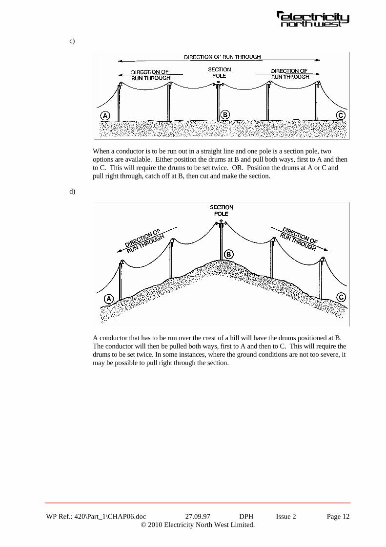
c)
When a conductor is to be run out in a straight line and one pole is a section pole, two options are available. Either position the drums at B and pull both ways, first to A and then to C. This will require the drums to be set twice. OR. Position the drums at A or C and pull right through, catch off at B, then cut and make the section.
d)
A conductor that has to be run over the crest of a hill will have the drums positioned at B. The conductor will then be pulled both ways, first to A and then to C. This will require the drums to be set twice. In some instances, where the ground conditions are not too severe, it may be possible to pull right through the section.
WP Ref.: 420\Part_1\CHAP06.doc 27.09.97 DPH Issue 2 Page 12 © 2010 Electricity North West Limited.

e)
There are two methods that can be used when a conductor has to be run through the trough of a hill. Either position the drums at B and pull up first to A and then to C. This will require the drums to be set twice. OR. Position the drums at A or C and pull right through, catch off at B, then cut and make the section.
f)
When a conductor has to be run out on the flat but with the added complication of a change in direction, two methods are allowed. Either position the drums at B and pull both ways, first to A and then to C. This will require the drums to be set twice. OR. Position the drums at A or C and pull right through, using angle rollers at B, catch off at B, then cut and make the section.
WP Ref.: 420\Part_1\CHAP06.doc 27.09.97 DPH Issue 2 Page 13 © 2010 Electricity North West Limited.

g)
When a conductor is to be run through an area which is obstructed by bushes/shrubs, the drums should be positioned at A or C and pulled through allowing enough clearance for the obstruction. This can be done by positioning a member of the working party at B who holds a rope around the conductor to prevent it being caught in the obstruction. When the conductor is being tensioned the person holding the rope will guide the conductor until it is clear of the obstruction. A captive roller should be used on the poles at each side of the obstruction to ensure that any sudden release of tension can be controlled.
WP Ref.: 420\Part_1\CHAP06.doc 27.09.97 DPH Issue 2 Page 14 © 2010 Electricity North West Limited.

h) Equalising tensions using a sagging block
WP Ref.: 420\Part_1\CHAP06.doc 27.09.97 DPH Issue 2 Page 15 © 2010 Electricity North West Limited.

WP Ref.: 420\Part_1\CHAP06.doc 27.09.97 DPH Issue 2 Page 16 © 2010 Electricity North West Limited.
7. WORKING PROCEDURES
7.1 Procedure 06/01 - Conductor erection.
7.2 Procedure 06/02 - Re-stringing.
8. ASSOCIATED DRAWINGS
HQ.A1.51.09-600 Running earth. 900000-53-019 Stabiliser backstay. 900000-53-020 Temporary backstay. 900000-53-034 Tensioning conductors using sag boards.

WP Ref.: 420\Part_1\CHAP06.doc 27.09.97 DPH Issue 2 Page 17 © 2010 Electricity North West Limited.

WP Ref.: 420\Part_1\CHAP06.doc 27.09.97 DPH Issue 2 Page 18 © 2010 Electricity North West Limited.

WP Ref.: 420\Part_1\CHAP06.doc 27.09.97 DPH Issue 2 Page 19 © 2010 Electricity North West Limited.

WP Ref.: 420\Part_1\CHAP06.doc 27.09.97 DPH Issue 2 Page 20 © 2010 Electricity North West Limited.
WP Ref.: 420\Part_1\CHAP06.doc 27.09.97 DPH Issue 2 Page 20 © 2010 Electricity North West Limited.