channel scaling for rounding noise reduction in … · channel scaling for rounding noise reduction...
TRANSCRIPT

Channel Scaling for Rounding Noise Reduction in Minimum Lifting 3D Wavelet Transform
Fairoza Amira Binti Hamzah*, Taichi Yoshida*, Masahiro Iwahashi* and Hitoshi Kiya† * Nagaoka University of Technology, Nagaoka, Japan
† Tokyo Metropolitan University, Tokyo, Japan
Abstract— An integer transform is used in lossless-lossy coding since it can reconstruct an input signal without any loss at output of the backward transform. Recently, its number of lifting steps is reduced as well as delay from input to output introducing multi-dimensional memory accessing. However it has a problem that quality of the reconstructed signal in lossy coding has its upper bound in the rate distortion curve. This is because the noise generated by rounding operations in each lifting step inside the integer transform does not contribute to data compression. This paper tries to reduce the rounding noise observed at output of the integer transform introducing channel scaling inside the transform. As a result of experiments, it was observed that the proposed method improves quality of the decoded signal in lossy coding mode.
I. INTRODUCTION
This paper deals with a picture quality degradation problem due to integer implementation of a three dimensional (3D) lifting wavelet transform (WT). In an integer implementation, signal values inside the transform are rounded to integers. Shorter word length of the integer contributes to smaller memory space and faster calculation [1,2]. However it generates noise due to the rounding (rounding noise).
In the lifting WT, the rounding noise does not appear at output of the backward transform as far as the output signal values of the forward WT are fed into the backward WT without any alteration. Therefore it is applied to lossless coding of signals. Lossless coding based on the 5/3 WT in the JPEG 2000 is an example for this case [3]. However the rounding noise appears at output of the backward WT in lossy coding in which the quantization and its inverse are inserted between the forward WT and the backward WT. Lossy coding based on the 9/7 WT is an example for this case [3].
Unlike the quantization noise, the rounding noise is independent of the bit rate (compression ratio). Therefore the rounding noise appears as the upper bound of the rate distortion curve (the bit rate versus the peak signal to noise ratio) in high bit rate lossy coding. This paper tries to reduce the rounding noise of the minimum lifting WT by introducing the channel scaling to increase the upper bound.
Recently, based on non-separable structure [4,5], the minimum lifting WT which has less number of lifting steps in cascade comparing to the conventional separable structure has been reported [6-11]. It contributes to reduce delay from input to output under a parallel signal processing architecture. This
is because a lifting step must wait for a calculation result of the previous lifting step.
The minimum lifting WT based on the 5/3 WT was been reported for 2D signals in [6]. It was extended to 3D signals in [7]. In both cases, the total number of lifting steps was decreased as well as the variance of the rounding noise. Similarly, the minimum lifting 2D WT based on the 9/7 WT was reported in [8-10]. It was extended to 3D case in [11]. However, unlike the 5/3 WT, the variance of the rounding noise is increased in the 9/7 WT even though the number of lifting steps is decreased.
This paper reduces the rounding noise of the minimum lifting WT based on the 9/7 WT for 3D case by introducing channel scaling. The 3D WT has eight channels. In all channels, the maximum absolute value (MAV) of signals inside the transform is limited by word length of signals in its integer implementation. Using a fact that MAV in each channel is not the same, we introduce different scaling in each channel. The channel scaling is designed so that 1) each channel has almost the same MAV inside the transform, 2) output signal values of the transform are not changed, and 3) rounding noises generated inside the transform are reduced at output of the transform.
II. MINIMUM LIFTING WAVELET
Figure 1 illustrates the forward transform of the 3D WT based on the “separable” structure. The input signal
3213
3
2
2
1
1
321
1
0
1
0
1
0
)()( nnnN
n
N
n
N
n
zzzxX
nz (1)
where (z)=(z1, z2, z3) and (n)=(n1, n2, n3) is decomposed into 8 subgroups X000, X001, ,X111 depending on parity of the pixel location (n). In its integer implementation, signal values are multiplied with 2F and rounded to integers. In the 1st lifting step, X100 in channel (Ch) 5 is predicted from X000 in Ch1 with a filter V1. Note that signal values of the prediction are rounded to integers. Similarly, Ch6, Ch7 and Ch8 are predicted from Ch2, Ch3 and Ch4, respectively. There predictions are performed simultaneously under a parallel processing platform. However the updating in the 2nd lifting must wait for calculation results of the 1st lifting step. It means that this structure takes long delay from input to output since it has 12 lifting steps.
Proceedings of APSIPA Annual Summit and Conference 2015 16-19 December 2015
978-988-14768-0-7©2015 APSIPA 888 APSIPA ASC 2015

Figure 2 illustrates the forward transform of the 3D WT based on the “non-separable” structure [11]. In this structure, the total number of the lifting steps is reduced from 12 to 8. It contributes to decrease the delay. If there is no rounding, both of Fig. 1 and Fig. 2 have the same output for the same input. However, if F is very small, they have different amount of the rounding noise at their output. Unfortunately, Fig. 2 has greater amount of the rounding noise even though the number of lifting steps is decreased comparing to Fig. 1. This paper tries to reduce the variance of the rounding noise at output of the transform by introducing the channel scaling explained in the next section.
Note that the filters V1, V2, V3, V4 are defined as
4,2,3,1,)1(
)1(
)(
)(1
1
11
qpzh
zh
V
V
q
p
q
p
z
z. (2)
Similarly, other filters are defined as
,)1(
)1(
)(
)(,
)1(
)1(
)(
)(1
3
13
12
12
zh
zh
D
D
zh
zh
H
H
q
p
q
p
q
p
q
p
z
z
z
z (3)
where the filter coefficients hp and hq are defined in the JPEG 2000 as the 9/7 WT as well as the coefficient k in the figure.
D1 D2
YLLL
YLLH
V3
V3
V3
V3 V4
V4
V4
V4
H3
H3
H3
H3
H4
H4
H4
H4
D1 D2
D1 D2
D1 D2
YLHL
YLHH
YHLL
YHLH
YHHL
YHHH
3 4 7 8 9 10
V1
V1
V1
V1 V2
V2
V2
V2
1 2
H1
H1
H1
H1
H2
H2
H2
H2
5 6
D3 D4
D3 D4
D3 D4
D3 D4
11 12
k-1 2-F
k+1 2-F
k-1 2-F
k+1 2-F
k-1 2-F
k+1 2-F
k-1 2-F
k+1 2-F
k-1
k-1
k-1
k-1
k+1
k+1
k+1
k+1
k-1
k-1
k+1
k+1
k-1
k-1
k+1
k+1
X000
X001
X010
X011
X100
X101
X110
X111
↓22
z3 ↓23
↓23
↓22
z3 ↓23
↓23z2
↓22
z3 ↓23
↓23
↓22
z3 ↓23
↓23z2
z1 ↓21
↓21X2+F
2+F
2+F
2+F
2+F
2+F
2+F
2+F
= rounding
Fig. 1 Separable 3D structure
X000
X001
X010
X011
X100
X101
X110
X111
H1
H1D1
V1
V1H1
V1H1D1
V1D1
H2
D2
V1
-H2D2
H1
V2
D1
H1D1
D1
H2
V1
V1D1
D2
H1
V2
-V2D2D2
V1
H1
V1H1
D1
H2
D2
-H2D2
V2
-V2H2
-V2D2
+V2H2D2
1 2 3 4
H3
H3D3
V3
V3H3
V3H3D3
V3D3
H4
D4
V3
-H4D4
H3
V4
D3
H3D3
D3
H4
V3
V3D3
D4
H3
V4
-V4D4D4
V3
H3
V3H3
D3
H4
D4
-H4D4
V4
-V4H4
-V4D4
V4H4D4
5 6 7 8
YLLL
YLLH
YLHL
YLHH
YHLL
YHLH
YHHL
YHHH
k-3 2-F
k-1 2-F
k-1 2-F
k+1 2-F
k-1 2-F
k+1 2-F
k+1 2-F
k+3 2-F
V2
H2
-V2H2
D1
V4
H4
-V4H4
D3
2+F
2+F
2+F
2+F
2+F
2+F
2+F
2+F
Fig. 2 Non-separable 3D structure without channel scaling (existing method).
Proceedings of APSIPA Annual Summit and Conference 2015 16-19 December 2015
978-988-14768-0-7©2015 APSIPA 889 APSIPA ASC 2015

X000
X001
X010
X011
X100
X101
X110
X111
2+F s1
2+F s2
2+F s3
2+F s4
2+F s5
2+F s6
2+F s7
2+F s8
H1s68
H1D1s58
V1s48
V1H1s28
V1H1D1s18
V1D1s38
H2s75
D2s65
V1s15
-H2D2s85
H1s24
V2s84
D1s34
H1D1s14
D1s56
H2s86
V1s26
V1D1s16
D2s43
H1s13
V2s73
-V2D2s83
D2s87
V1s37
H1s57
V1H1s17 H2s31
D2s21
-H2D2s41
V2s51
-V2H2s71
-V2D2s61
+V2H2D2s81
1 2 3 4
V2s62
H2s42
-V2H2s82
D1s12
D1s78
5, 6, 7
YLLL
YLLH
YLHL
YLHH
YHLL
YHLH
YHHL
YHHH
k-3 2-F s1-1
k-1 2-F s2-1
k-1 2-F s3-1
k+1 2-F s4-1
k-1 2-F s5-1
k+1 2-F s6-1
k+1 2-F s7-1
k+3 2-F s8-1
H4s31
D4s21
-H4D4s41
V4s51
-V4H4s71
-V4D4s61
+V4H4D4s81
8
Fig. 3 Non-separable 3D structure with channel scaling (proposed method).
III. PROPOSED METHOD
Figure 3 illustrates the proposed method. It has the minimum number of the lifting steps as the same as the existing method in Fig. 2. Unlike the existing method, the scaling parameters s1, s2, , s8 are introduced so that each channel has almost the same maximum absolute value (MAV). If there is no such scaling, each channel has different MAV. It means that the dynamic range for signal values of the integer implementation is not fully utilized inside the transform. Fig. 3 also has other parameters
}8,,2,1{,/ qpforsss pqpq . (4)
Those are introduced so that output signal values of the transform becomes the same as the existing method if there is no rounding noise. In the proposed method, signal values are multiplied with different parameters sp in each channel before the 1st lifting step. In the inter channel prediction and up-dating, scales are balanced with other parameters spq. Finally, both of the signal value and the rounding noise are divided with the parameters sp in each channel. As a result, the rounding noise generated inside the transform is reduced at output of the transform without changing the signal values. In detail, MAV mp in channel p{1,2, ,8} of the existing method are measured for an input signal. Next, the parameters sp are set as
1
821 ,,,max pp mmmms . (5)
As a result, the parameters of this channel scaling becomes greater than or equal to one. In contrast, the existing method sets all parameters to one.
IV. EXPERIMENTAL RESULTS
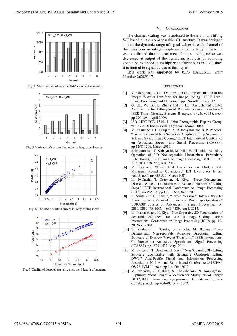
In the following experiments, a 3D AR(1) model was used as the input signal to the forward WT. Its auto-correlation coefficient was set to ρ = 0.9. The range of signal values is set to [-128, 127], namely 8 bit depth. Figure 4 summarizes MAV in each channel at F=0. Before the channel scaling (scl_OFF), each channel had different MAV. After, the channel scaling (scl_ON), all channels have almost the same MAV (=1024). It means that the dynamic range [-1024, 1023] of signal values at each channel in 11 bit-depth integer implementation is fully utilized. Figure 5 summarizes the variance of the rounding noise measured at output of the forward WT in each channel at F=0. For example, the variance is reduced from 6.1 to 1.62 in channel 8. In average, it is reduced from 3.13 to 0.56. it was observed that the rounding noise is reduced to 17.9 (%) at output of the forward WT by the channel scaling. Figure 6 illustrates the rate-distortion curves. The horizontal axis and the vertical axis indicates the bit rate (= compressed data volume) and the peak signal to noise ratio (PSNR), respectively. Both of the forward and the backward transforms are implemented as integer transforms at F=0. After the forward transform, the quantization and the entropy coding are embedded to compress its data volume. It was observed that quality of decoded signals measured with PSNR is improved from 43.0 (dB) to 46.6 (dB) at 4.14 (bpp). Quality of decoded signals in high quality (= high bit rate) lossy coding is improved by the proposed method.
Figure 7 indicates the bit depth = log2(MAV) +1 +F (bit) versus PSNR of the output signal from the backward WT at F=8 and the forward WT at F=0. There is no quantization between them. It was observed that the proposed method reduces the rounding noise by 4 (dB).
Proceedings of APSIPA Annual Summit and Conference 2015 16-19 December 2015
978-988-14768-0-7©2015 APSIPA 890 APSIPA ASC 2015
128
256
512
1024
2048
1 2 3 4 5 6 7 8
max
imu
m
channel
scl_OFF scl_ON
Fig. 4 Maximum absolute value (MAV) in each channel.
0
1
2
3
4
5
6
7
1 2 3 4 5 6 7 8
no
ise
vari
ance
channel
scl_OFF scl_ON
Fig. 5 Variance of the rounding noise in frequency domain.
36
38
40
42
44
46
48
0 0.5 1 1.5 2 2.5 3 3.5 4 4.5
PSN
R (
dB
)
bit rate (bpp)
scl_ON
scl_OFF
Fig. 6 The rate-distortion curves in lossy coding mode.
38
40
42
44
46
48
50
52
7.5 8 8.5 9 9.5 10 10.5
PSN
R (
dB
)
bit depth of inner signal
scl_ON
scl_OFF
Fig. 7 Quality of decoded signals versus word length of integers.
V. CONCLUSIONS
The channel scaling was introduced to the minimum lifting WT based on the non-separable 3D structure. It was designed so that the dynamic range of signal values at each channel of the transform in integer implementation is fully utilized. It was confirmed that the variance of the rounding noise was decreased at output of the transform. Analysis on rounding should be extended to multiplier coefficients as in [12], since it is limited to signal values in this paper.
This work was supported by JSPS KAKENHI Grant Number 26289117.
REFERENCES
[1] M. Grangetto, et. al., “Optimization and Implementation of the Integer Wavelet Transform for Image Coding,” IEEE Trans. Image Processing, vol.11, Issue 6, pp. 596-604, June 2002.
[2] G. Shi, W. Liu, Li Zhang and Fu Li, “An Efficient Folded Architecture for Lifting-based Discrete Wavelet Transform,” IEEE Trans. Circuits, Systems II express briefs, vol.56, no.4, pp.290 -294, April 2009.
[3] ISO / IEC FCD 15444-1, Joint Photographic Experts Group, “JPEG 2000 Image Coding System,” March 2000.
[4] M. Kaaniche, J. C. Pesquet, A. B. Benyahia and B. P. Popescu, “Two-dimensional Non Separable Adaptive Lifting Scheme for Still and Stereo Image Coding,” IEEE International Conference on Acoustics, Speech, and Signal Processing (ICASSP), pp.1298-1301, March 2010.
[5] S. Muramatsu, T. Kobayashi, M. Hiki, H. Kikuchi, “Boundary Operation of 2-D Non-separable Linear-phase Paraunitary Filter Banks,” IEEE Trans. on Image Processing, DOI 10.1109/ TIP. 2011.2181527, Apr. 2012.
[6] M. Iwahashi, “Four Band Decomposition Module with Minimum Rounding Operations,” IET Electronics letters, vol.43, no.6, pp.333-335, March 2007.
[7] M. Iwahashi, T. Orachon, H. Kiya, “Three Dimensional Discrete Wavelet Transform with Reduced Number of Lifting Steps,” IEEE International Conference on Image Processing (ICIP), no.WA.L4, pp.1651-1654, Sept. 2013.
[8] T. Strutz and I. Rennert, “Two-dimensional Integer Wavelet Transform with Reduced Influence of Rounding Operations,” EURASIP Journal on Advances in Signal Processing, vol. 2012, 2012: 75, ISSN: 1687-6180, April, 2012.
[9] M. Iwahashi, and H. Kiya, “Non Separable 2D Factorization of Separable 2D DWT for Lossless Image Coding,” IEEE International Conference on Image Processing (ICIP), pp. 17-20, Nov. 2009.
[10] T. Yoshida, T. Suzuki, S. Kyochi, M. Ikehara, “Two Dimensional Non-separable Adaptive Directional Lifting Structure of Discrete Wavelet Transform,” IEEE International Conference on Acoustics, Speech and Signal Processing (ICASSP), pp.1529-1532, May, 2011.
[11] M. Iwahashi, T. Orachon, H. Kiya, “Non Separable 3D Lifting Structure Compatible with Separable Quadruple Lifting DWT,” Asia-Pacific Signal and Information Processing Association 2013 Annual Summit and Conference (APSIPA), OS.26, IVM.11, no.4, pp.1-4, Oct. 2013.
[12] M. Iwahashi, O. Nishida, S. Chokchaitam, N. Kambayashi, "Optimum Word Length Allocation for Multipliers of Integer DCT", IEEE International Symposium on Circuits and Systems (ISCAS), vol.II, pp.400-403, May 2003.
Proceedings of APSIPA Annual Summit and Conference 2015 16-19 December 2015
978-988-14768-0-7©2015 APSIPA 891 APSIPA ASC 2015