changes required to the existing sample componentry · - 3 - sdo - c contents ... on a clean,...
TRANSCRIPT
- 1 -
802-001-02 D

- 2 - SDO - C
Delete top and bottom bor
- 3 - SDO - C
CONTENTS
Important Safety Recommendations ………………………………………............. 4
Warranty Exclusions ………………………………………………………………. 5
Assembly Instructions ………………………………………………………………. 6
Identifying Garage Door Type ………………………………………………………………. 6
Assembling Drive Rail and Power Head ………………………………………………………. 6
Drive Chain Assembly & Tensioning ………………………………………………………. 7
Installation Instructions ……………………………………………………………… 8
Mounting Header Bracket ………………………….……………………………........... 8
Mounting Towing Bracket ……………………………………………………………… 8
Attaching Drive Rail to Header Bracket ……………………………………………… 8
Mounting Power Head to Ceiling ……………………………………………………… 9
Attaching Towing Arms ……………………………………………………………… 9
Adjusting Disengage Cords ……………………………………………………………… 10
Connecting to Power Supply ………………………............................................................ 10
Settings and Adjustments ……………………………………………………………… 11
Disengaging from Garage Door ……………………………………………………………… 11
Engaging to Garage Door ……………………………………………………………… 11
Travel Adjustment ……………………………………………………………… 11
Safety Obstruction Force Adjustment ……………………………………………………… 12
Hand Transmitters ……………………………………………………………………… 13 Options and Features ……………………………………………………………… 14
Auto Close ……………………………………………………………………………… 14
Courtesy Lamp ……………………………………………………………………………… 14
Dip Switches ……………………………………………………………………… 14
Learn Button ……………………………………………………………………………… 15
LED Indicator ……………………………………………………………………………… 15
Output Terminals ……………………………………………………………………………… 15
Run Button ……………………………………………………………………… 15
Safety Beams ……………………………………………………………………… 15
Thermal Overload ……………………………………………………………………… 16
Wall Switch (hard wired) ……………………………………………………………… 17
Wall Switch (wireless) ……………………………………………………………… 17
Technical Specifications ……………………………………………………………… 17 Trouble Shooting Guide ……………………………………………………………… 18
Notes ……………………………………………………………………………………… 19

- 4 - SDO - C
IMPORTANT SAFETY RECOMMENDATIONS
FAILURE TO COMPLY WITH THE FOLLOWING SAFETY RECOMMENDATIONS
MAY RESULT IN SERIOUS PERSONAL INJURY, DEATH AND / OR PROPERTY
DAMAGE.
1. PLEASE READ CAREFULLY AND ADHERE TO ALL SAFETY AND INSTALLATION
RECOMMENDATIONS
2. The installation of your new Automatic Garage Door Opener (herein after referred to as “AGDO”)
must be carried out by a technically qualified or licensed person. Attempting to install or repair the
AGDO without suitable technical qualification may result in severe personal injury, death and / or
property damage.
3. The AGDO must only be installed on a properly balanced well functioning garage door. An improperly
balanced or malfunctioning garage door could cause serious personal injury, death and / or property and / or
the AGDO damage. Have a qualified person check and if required, make repairs to your garage door before
installing the AGDO. A manually operated garage door is deemed to be well balanced and aligned if it;
i. requires an equivalent amount of applied force to either manually open or close, and
ii. requires no more than 150N (15kg) of applied force to either manually open or close, and
iii. does not rise or fall more than 100mm when released at any point between fully open or fully
closed positions, and
iv. does not rub on or incorrectly make contact with any supporting or surrounding structures.
4. Repairs to the garage door must be carried out by a technically qualified person. Attempting to repair the
garage door without suitable technical qualification may result in severe personal injury, death and / or
property and / or AGDO damage.
5. Remove or render inoperative all existing locks and ropes prior to installation of the AGDO.
6. The counter balance springs on sectional type garage doors must be lubricated annually between each of the
coils with heavy automotive bearing grease. Failure to adequately lubricate the springs may result in one or
more of the following symptoms:
a. Counter balance springs may become rusty over time resulting in additional operating friction
between the coils which may cause the AGDO to malfunction.
b. Seasonal temperature changes may cause the garage door springs to expand and / or contract. The
resultant increase and / or decrease in operating friction may cause the AGDO to malfunction.
Properly lubricating the springs will help to minimize changes in operating friction due to the
effects of seasonal temperature change.
7. Where possible, install the AGDO at least 2 meters or more above the ground. Adjust the Engage / Disengage
Cord so that it hangs approximately 1.8 meters from the ground.
8. The Engage / Disengage Instruction Tag must remain attached to the Engage / Disengage Cord.
9. Locate the Wall Switch;
i. within site of the garage door, and
ii. at a minimum height of 1.5 meters above the ground so that it remains out of the reach of small
children, and
iii. away from all moving parts of the garage door.
10. The Entrapment Warning Label must be secured in a prominent position adjacent to the Wall Switch.
11. The AGDO must be connected to a properly earthed general purpose 230 ~ 240VAC power outlet which has
been installed by a qualified electrical contractor.
12. Do not connect the AGDO to the power outlet until this manual instructs you to do so.
13. Subsequent to installing and adjusting the AGDO the garage door must stop and reverse direction when it
comes into contact with a 35mm high solid object placed on the floor under the garage door.
14. The correct function of the Safety Obstruction Force System should be checked on a monthly basis.
- 5 - SDO - C
IMPORTANT SAFETY RECOMMENDATIONS
15. Never use the AGDO unless the garage door is in full view and free from any object which may impede the
movement of the garage door such as cars, children and / or adults.
16. Never allow children to operate the AGDO.
17. Never operate the AGDO when any persons are under or near the path of the garage door. Children must be
supervised at all times when near the garage door and when the AGDO is in use.
18. Never attempt to disengage the AGDO to manual operation when there are children / persons and / or solid
objects including motor vehicles under or near the path of the garage door as the garage door may fall sharply
upon manual release from the AGDO.
19. Never attempt to open or close the garage door by pulling on the Engage / Disengage Cord.
20. Never attempt to make any repairs or remove covers from the AGDO without first disconnecting the power
supply cord from main power supply.
21. Removal of the AGDO’s protective covers must only be performed by a technically qualified person.
Attempting to remove the protective covers or repair the AGDO without suitable technical qualification may
result in severe personal injury, death and / or property damage.
22. For additional safety we strongly recommend the inclusion of Safety Beams. Although the AGDO
incorporates a pressure sensitive Safety Obstruction Force system the addition of Safety Beams will greatly
enhance the operating safety of an automatic garage door and provide additional peace of mind. In some
countries it is a mandate of law to fit Safety Beams. It is the sole responsibility of the owner / installer to fit
Safety Beams in those countries that so require.
23. Always ensure that the garage door is fully open and stationary before driving in or out of the garage.
24. Always ensure the garage door is fully closed and stationary before moving out of its view.
25. Adjustments to the Safety Obstruction Force settings must only be carried out by a technically qualified
person. Attempting to adjust the settings without suitable technical qualification may result in severe personal
injury, death and / or property and / or AGDO damage.
26. Keep hands and loose clothing clear of the AGDO and garage door at all times.
27. In order for the Safety Obstruction Force system to function it must first encounter an obstruction in the form
of an object / person on to which some force MUST be exerted. As a result the object / person / garage door
may suffer DAMAGE AND / OR INJURY.
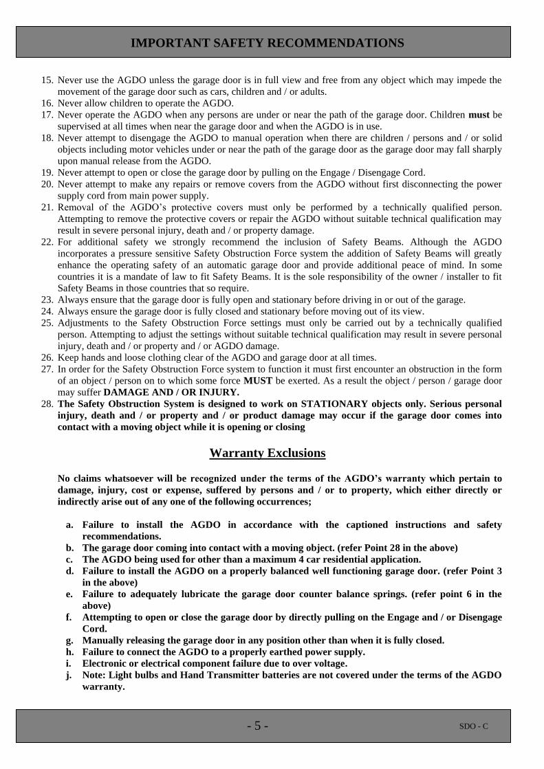
28. The Safety Obstruction System is designed to work on STATIONARY objects only. Serious personal
injury, death and / or property and / or product damage may occur if the garage door comes into
contact with a moving object while it is opening or closing
Warranty Exclusions
No claims whatsoever will be recognized under the terms of the AGDO’s warranty which pertain to
damage, injury, cost or expense, suffered by persons and / or to property, which either directly or
indirectly arise out of any one of the following occurrences;
a. Failure to install the AGDO in accordance with the captioned instructions and safety
recommendations.
b. The garage door coming into contact with a moving object. (refer Point 28 in the above)
c. The AGDO being used for other than a maximum 4 car residential application.
d. Failure to install the AGDO on a properly balanced well functioning garage door. (refer Point 3
in the above)
e. Failure to adequately lubricate the garage door counter balance springs. (refer point 6 in the
above)
f. Attempting to open or close the garage door by directly pulling on the Engage and / or Disengage
Cord.
g. Manually releasing the garage door in any position other than when it is fully closed.
h. Failure to connect the AGDO to a properly earthed power supply.
i. Electronic or electrical component failure due to over voltage.
j. Note: Light bulbs and Hand Transmitter batteries are not covered under the terms of the AGDO
warranty.
- 6 - SDO - C
ASSEMBLY INSTRUCTIONS
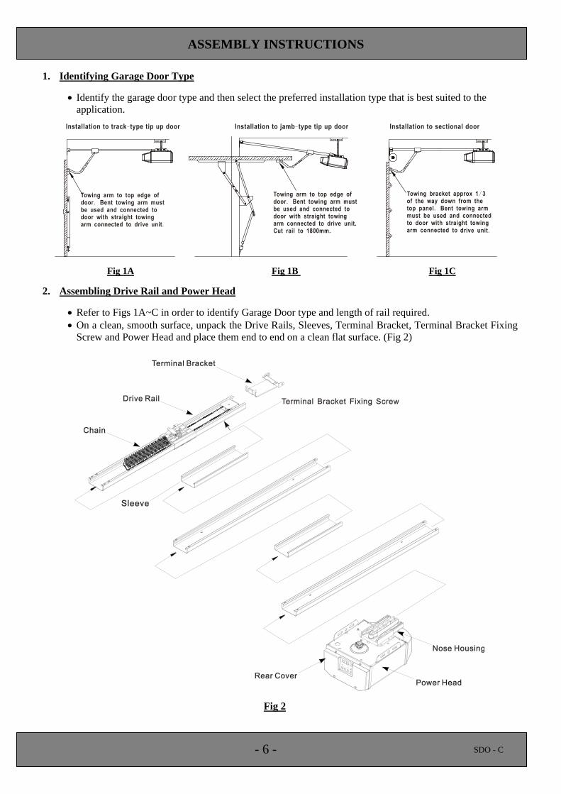
1. Identifying Garage Door Type
Identify the garage door type and then select the preferred installation type that is best suited to the
application.
Fig 1A Fig 1B Fig 1C
2. Assembling Drive Rail and Power Head
Refer to Figs 1A~C in order to identify Garage Door type and length of rail required.
On a clean, smooth surface, unpack the Drive Rails, Sleeves, Terminal Bracket, Terminal Bracket Fixing
Screw and Power Head and place them end to end on a clean flat surface. (Fig 2)
Fig 2
- 7 - SDO - C
ASSEMBLY INSTRUCTIONS
Insert the Terminal Bracket into the Drive Rail section labeled “towards door”.
Affix the Terminal Bracket Fixing Screw which locks the terminal bracket to the drive rail. (Fig.2)
Align and insert each Sleeve into a Drive Rail in accordance with the labeling stickers and push them
together until the Drive Rails are fully abutted and form one Fully Assembled Rail.
Take the Fully Assembled Rail and insert it onto the Nose Housing of the Power Head. (Fig.2)
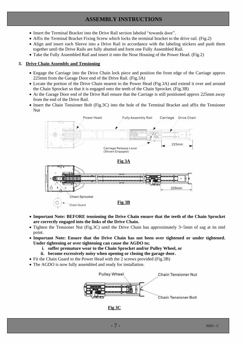
3. Drive Chain Assembly and Tensioning
Engage the Carriage into the Drive Chain lock piece and position the front edge of the Carriage approx
225mm from the Garage Door end of the Drive Rail. (Fig.3A)
Locate the portion of the Drive Chain nearest to the Power Head (Fig.3A) and extend it over and around
the Chain Sprocket so that it is engaged onto the teeth of the Chain Sprocket. (Fig.3B)
At the Garage Door end of the Drive Rail ensure that the Carriage is still positioned approx 225mm away
from the end of the Drive Rail.
Insert the Chain Tensioner Bolt (Fig.3C) into the hole of the Terminal Bracket and affix the Tensioner
Nut
Fig 3A
Fig 3B
Important Note: BEFORE tensioning the Drive Chain ensure that the teeth of the Chain Sprocket
are correctly engaged into the links of the Drive Chain.
Tighten the Tensioner Nut (Fig.3C) until the Drive Chain has approximately 3~5mm of sag at its mid
point.
Important Note: Ensure that the Drive Chain has not been over tightened or under tightened.
Under tightening or over tightening can cause the AGDO to;
i. suffer premature wear to the Chain Sprocket and/or Pulley Wheel, or
ii. become excessively noisy when opening or closing the garage door.
Fit the Chain Guard to the Power Head with the 2 screws provided (Fig.3B)
The AGDO is now fully assembled and ready for installation.
Fig 3C
- 8 - SDO - C
INSTALLATION INSTRUCTIONS
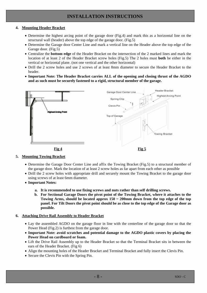
4. Mounting Header Bracket
Determine the highest arcing point of the garage door (Fig.4) and mark this as a horizontal line on the
structural wall (header) above the top edge of the garage door. (Fig.5)
Determine the Garage door Center Line and mark a vertical line on the Header above the top edge of the
Garage door. (Fig.5)
Centralize the bottom edge of the Header Bracket on the intersection of the 2 marked lines and mark the
location of at least 2 of the Header Bracket screw holes (Fig.5) The 2 holes must both be either in the
vertical or horizontal plane. (not one vertical and the other horizontal)
Drill the 2 screw holes and use 2 screws of at least 8mm diameter to secure the Header Bracket to the
header.
Important Note: The Header Bracket carries ALL of the opening and closing thrust of the AGDO
and as such must be securely fastened to a rigid, structural member of the garage.
Fig 4 Fig 5
5. Mounting Towing Bracket
Determine the Garage Door Center Line and affix the Towing Bracket (Fig.5) to a structural member of
the garage door. Mark the location of at least 2 screw holes as far apart from each other as possible
Drill the 2 screw holes with appropriate drill and securely mount the Towing Bracket to the garage door
using screws of at least 6mm diameter.
Important Notes:
a. It is recommended to use fixing screws and nuts rather than self drilling screws.
b. For Sectional Garage Doors the pivot point of the Towing Bracket, where it attaches to the
Towing Arms, should be located approx 150 ~ 200mm down from the top edge of the top
panel. For Tilt Doors the pivot point should be as close to the top edge of the Garage door as
possible.
6. Attaching Drive Rail Assembly to Header Bracket
Lay the assembled AGDO on the garage floor in line with the centerline of the garage door so that the
Power Head (Fig.2) is furthest from the garage door.
Important Note: avoid scratches and potential damage to the AGDO plastic covers by placing the
Power Head on cardboard or foam.
Lift the Drive Rail Assembly up to the Header Bracket so that the Terminal Bracket sits in between the
ears of the Header Bracket. (Fig 6)
Align the mounting holes of the Header Bracket and Terminal Bracket and fully insert the Clevis Pin.
Secure the Clevis Pin with the Spring Pin.
- 9 - SDO - C
INSTALLATION INSTRUCTIONS
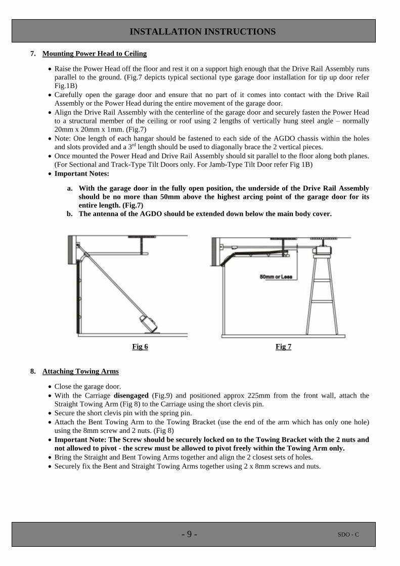
7. Mounting Power Head to Ceiling
Raise the Power Head off the floor and rest it on a support high enough that the Drive Rail Assembly runs
parallel to the ground. (Fig.7 depicts typical sectional type garage door installation for tip up door refer
Fig.1B)
Carefully open the garage door and ensure that no part of it comes into contact with the Drive Rail
Assembly or the Power Head during the entire movement of the garage door.
Align the Drive Rail Assembly with the centerline of the garage door and securely fasten the Power Head
to a structural member of the ceiling or roof using 2 lengths of vertically hung steel angle – normally
20mm x 20mm x 1mm. (Fig.7)
Note: One length of each hangar should be fastened to each side of the AGDO chassis within the holes
and slots provided and a 3rd length should be used to diagonally brace the 2 vertical pieces.
Once mounted the Power Head and Drive Rail Assembly should sit parallel to the floor along both planes.
(For Sectional and Track-Type Tilt Doors only. For Jamb-Type Tilt Door refer Fig 1B)
Important Notes:
a. With the garage door in the fully open position, the underside of the Drive Rail Assembly
should be no more than 50mm above the highest arcing point of the garage door for its
entire length. (Fig.7)
b. The antenna of the AGDO should be extended down below the main body cover.
Fig 6 Fig 7
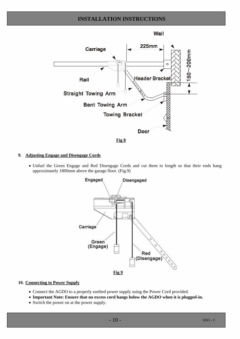
8. Attaching Towing Arms
Close the garage door.
With the Carriage disengaged (Fig.9) and positioned approx 225mm from the front wall, attach the
Straight Towing Arm (Fig 8) to the Carriage using the short clevis pin.
Secure the short clevis pin with the spring pin.
Attach the Bent Towing Arm to the Towing Bracket (use the end of the arm which has only one hole)
using the 8mm screw and 2 nuts. (Fig 8)
Important Note: The Screw should be securely locked on to the Towing Bracket with the 2 nuts and
not allowed to pivot - the screw must be allowed to pivot freely within the Towing Arm only.
Bring the Straight and Bent Towing Arms together and align the 2 closest sets of holes.
Securely fix the Bent and Straight Towing Arms together using 2 x 8mm screws and nuts.
- 10 - SDO - C
INSTALLATION INSTRUCTIONS
Fig 8
9. Adjusting Engage and Disengage Cords
Unfurl the Green Engage and Red Disengage Cords and cut them to length so that their ends hang
approximately 1800mm above the garage floor. (Fig.9)
Fig 9
10. Connecting to Power Supply
Connect the AGDO to a properly earthed power supply using the Power Cord provided.
Important Note: Ensure that no excess cord hangs below the AGDO when it is plugged-in.
Switch the power on at the power supply.
- 11 - SDO - C
SETTINGS AND ADJUSTMENTS
11. Disengaging from Garage Door
Pull down on the Red Coloured Disengage Cord (Fig.9) to disengage the AGDO from the Garage door.
Important Notes:
a. Never attempt to open/close the Garage door by pulling on the Disengage Cord. Doing so
may result in SERIOUS PERSONAL INJURY, PROPERTY AND/OR AGDO DAMAGE.
b. Always disengage the AGDO with the Garage door in the fully closed position.
c. If attempting to disengage the AGDO from any position other than with the garage door
fully closed ensure that there are no persons and/or property near or directly under the
path of the garage door.
12. Engaging to Garage Door
Open the garage door by hand so that it is approx 1 meter off the ground.
Pull down on the Green Coloured Engage Cord. (Fig 9)
Press the Green Coloured “Run” Button located on the Rear Cover of the AGDO. (Fig.11)
After a short time the AGDO will self-engage into the Carriage.
Important Note: If the AGDO runs for some time (first cycle) and then stops without engaging into
the Carriage press the Green Coloured “Run” Button again and the AGDO will self-engage on the
second cycle.
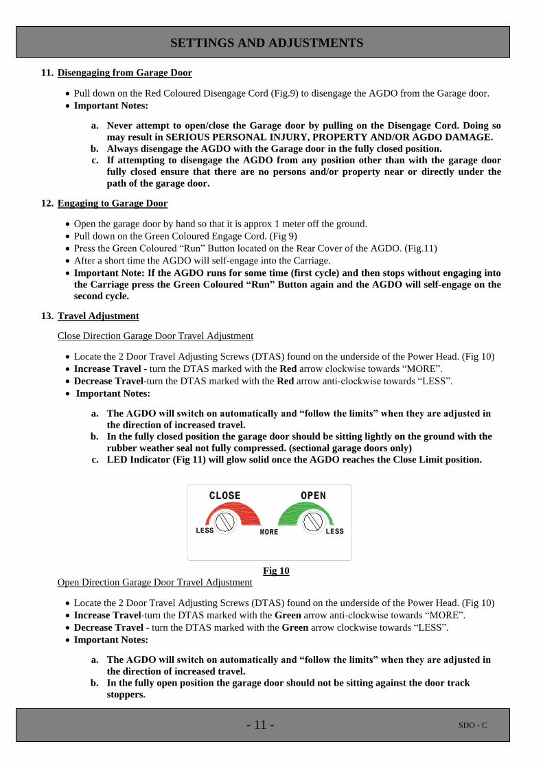
13. Travel Adjustment
Close Direction Garage Door Travel Adjustment
Locate the 2 Door Travel Adjusting Screws (DTAS) found on the underside of the Power Head. (Fig 10)
Increase Travel - turn the DTAS marked with the Red arrow clockwise towards “MORE”.
Decrease Travel-turn the DTAS marked with the Red arrow anti-clockwise towards “LESS”.
Important Notes:
a. The AGDO will switch on automatically and “follow the limits” when they are adjusted in
the direction of increased travel.
b. In the fully closed position the garage door should be sitting lightly on the ground with the
rubber weather seal not fully compressed. (sectional garage doors only)
c. LED Indicator (Fig 11) will glow solid once the AGDO reaches the Close Limit position.
CLOSE OPEN
LESS MORE LESS
RUNSET
CODE
UP FORCE
MIN MAX
DOWN FORCE
MIN MAX
SWITCHWALL
PHOTO BEAM
Fig 10
Open Direction Garage Door Travel Adjustment
Locate the 2 Door Travel Adjusting Screws (DTAS) found on the underside of the Power Head. (Fig 10)
Increase Travel-turn the DTAS marked with the Green arrow anti-clockwise towards “MORE”.
Decrease Travel - turn the DTAS marked with the Green arrow clockwise towards “LESS”.
Important Notes:
a. The AGDO will switch on automatically and “follow the limits” when they are adjusted in
the direction of increased travel.
b. In the fully open position the garage door should not be sitting against the door track
stoppers.
- 12 - SDO - C
SETTINGS AND ADJUSTMENTS
c. LED Indicator (Fig 11) will slow flash once the AGDO reaches the Open Limit position.
14. Safety Obstruction Force Adjustment
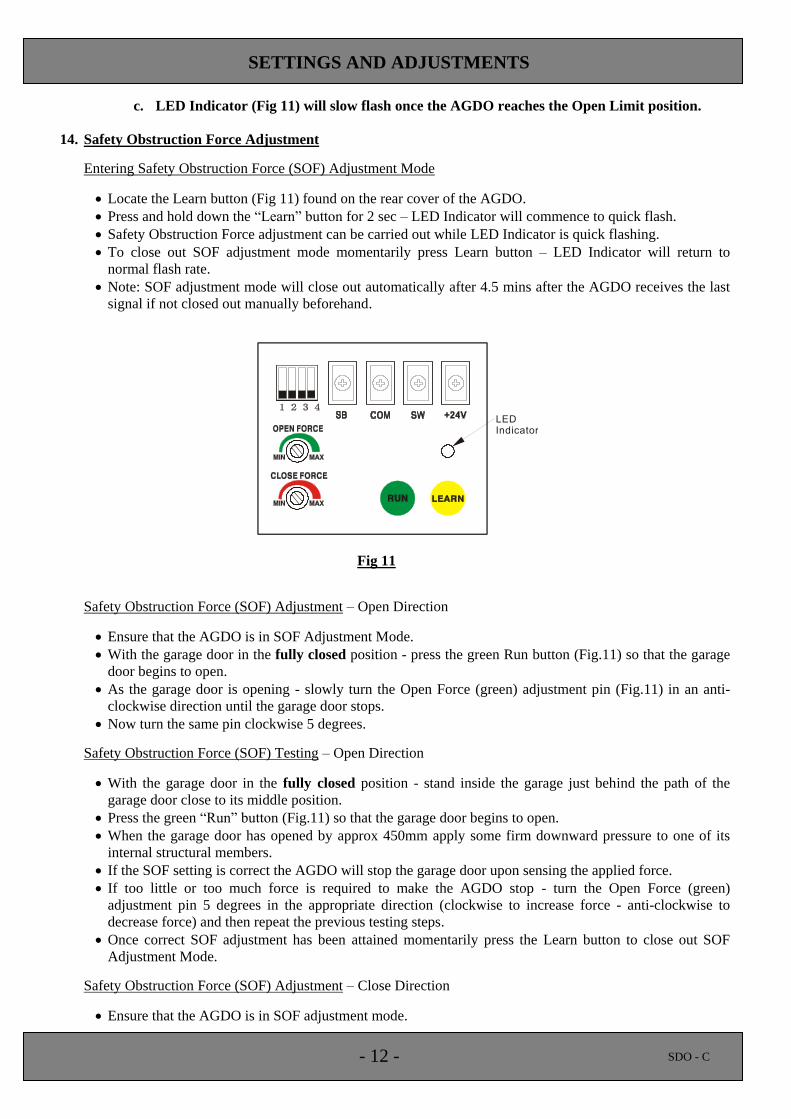
Entering Safety Obstruction Force (SOF) Adjustment Mode
Locate the Learn button (Fig 11) found on the rear cover of the AGDO.
Press and hold down the “Learn” button for 2 sec – LED Indicator will commence to quick flash.
Safety Obstruction Force adjustment can be carried out while LED Indicator is quick flashing.
To close out SOF adjustment mode momentarily press Learn button – LED Indicator will return to
normal flash rate.
Note: SOF adjustment mode will close out automatically after 4.5 mins after the AGDO receives the last
signal if not closed out manually beforehand.
Fig 11
Safety Obstruction Force (SOF) Adjustment – Open Direction
Ensure that the AGDO is in SOF Adjustment Mode.
With the garage door in the fully closed position - press the green Run button (Fig.11) so that the garage
door begins to open.
As the garage door is opening - slowly turn the Open Force (green) adjustment pin (Fig.11) in an anti-
clockwise direction until the garage door stops.
Now turn the same pin clockwise 5 degrees.
Safety Obstruction Force (SOF) Testing – Open Direction
With the garage door in the fully closed position - stand inside the garage just behind the path of the
garage door close to its middle position.
Press the green “Run” button (Fig.11) so that the garage door begins to open.
When the garage door has opened by approx 450mm apply some firm downward pressure to one of its
internal structural members.
If the SOF setting is correct the AGDO will stop the garage door upon sensing the applied force.
If too little or too much force is required to make the AGDO stop - turn the Open Force (green)
adjustment pin 5 degrees in the appropriate direction (clockwise to increase force - anti-clockwise to
decrease force) and then repeat the previous testing steps.
Once correct SOF adjustment has been attained momentarily press the Learn button to close out SOF
Adjustment Mode.
Safety Obstruction Force (SOF) Adjustment – Close Direction
Ensure that the AGDO is in SOF adjustment mode.
- 13 - SDO - C
SETTINGS AND ADJUSTMENTS
With the garage door in the fully open position, press the Run button (Fig.11) so that the garage door
begins to close.
As the garage door is closing - slowly turn the Close Force (red) adjustment pin (Fig.11) in an anti-
clockwise direction until the garage door stops and begins to reverse direction.
Now turn the same pin clockwise 5 degrees.
Safety Obstruction Force (SOF) Testing – Close Direction
With the garage door in the fully open position stand inside the garage just behind the path of the garage
door close to its middle position.
Place a 32mm thick block of wood under the line of the garage door (approx at the mid point of the
garage door) so that the garage door will close onto the block of wood.
Press the green “Run” button so that the garage door begins to close.
If the Safety Obstruction Force Adjustment is correct the AGDO will stop and reverse the direction of the
garage door upon sensing the block of wood.
If the AGDO stops but does not reverse then turn the Close Force adjustment pin 5 degrees in an anti-
clockwise direction. (Fig 11)
Once correct SOF adjustment has been attained momentarily press the Learn button to close out SOF
Adjustment Mode.
Note: Ensure that Close Direction Travel Adjustment has been set so that bottom of the garage door is
resting lightly on the floor of the garage. (refer Sec.13 for travel adjustment instructions)
15. Hand Transmitters
Code Learning
The AGDO can store up to 14 individual Hand Transmitter codes.
Hand Transmitters may be coded as follows;
i. locate one of the Hand Transmitters supplied with the AGDO
ii. momentarily press “Learn” button (Fig.11) – LED Indicator will glow solid
iii. momentarily press Hand Transmitter button – LED Indicator will extinguish
iv. momentarily press Hand Transmitter button again – LED Indicator will begin to medium flash -
programming is completed once the LED Indicator ceases to medium flash
To code additional Hand Transmitters repeat steps i ~ iv.
Code Learning sequence will close out automatically after 35 sec if no Transmitter Code has been
received.
Code Deleting
All Hand Transmitter codes may be deleted as follows;
i. momentarily press the “Learn” button located on the side of the AGDO (Fig.12) – LED Indicator
will glow solid
ii. momentarily press “Run” button – LED Indicator will flash rapidly – all Hand Transmitter Codes
will have been deleted once the LED Indicator ceases to rapid flash
Battery Replacement
Battery may be replaced as follows;
i. remove the fixing screw located under the sticker on the underside of the Hand Transmitter
ii. open the 2 halves of the Hand Transmitter and replace the battery with one of identical
specification
iii. clip the 2 halves of the case back together and replace the fixing screw
- 14 - SDO - C
OPTIONS AND FEATURES
16. Auto Close
Auto Close can enhance the security of your property by ensuring that your garage door is never
unintentionally left open.
Auto Close will automatically close the garage door;
i. 3 sec after reaching the fully open position - provided that a person or object has passed through
the Safety Beams within the Delay Time, or
ii. upon expiry of the user selected delay time – provided that a person or object has not passed
through the Safety Beams within the Delay Time.
Note: Auto Close will function only when used in conjunction with Safety Beams. (Refer Sec.23)
Enabling
The function select Dip Switches are contained within the rear cover of the AGDO
Select Dips 1 & 2 to the “ON” position. (Fig.11)
Delay Time Selection
Auto Close delay time may be configured according to the following table;
Delay (sec) Dip No. 3 Dip No. 4
15 off off
30 on off
45 off on
60 on on
17. Courtesy Lamp
The in built Courtesy Lamp will illuminate each time the AGDO is activated and then switch off
automatically 3 min after receiving the last Hand Transmitter or run signal.
Bulb Replacement
Remove Lamp Cover by lifting at the 2 uppermost inside edges.
Remove bulb by turning it in an anti-clockwise direction.
Replace bulb with identical 60W (maximum) Edison Screw rough construction.
Important Note: Replacing the bulb with a model greater than 60W will cause the light cover
and/or main cover to melt!
18. Dip Switches
The Dip Switches located within the back cover of the AGDO (Fig.11) enable or disable specific
functionality.
By reading through the section titled “Options and Features” the AGDO’s functionality can be
customized to individual requirements.
The functions of the Dip Switches are described in the following table;
Function Dip No. Dip Position Reference
Safety Beams (SB) - Enable 1 ON Sec.23
Auto Close (AC) - Enable 1 & 2 ON Sec.23
Auto Close Delay Time 3 & 4 Varies Sec.16
- 15 - SDO - C
OPTIONS AND FEATURES
19. Learn Button
The Learn button (Fig 11) is located on the rear cover of the AGDO and serves to initiate the functions as
described in the following table;
Function Action Reference
Learn Hand Transmitter Codes Momentary press Sec.15
Delete Hand Transmitter Codes Press and hold while powering-up Sec.15
Entering SOF Adjustment Mode Press and hold for 2 sec. Sec.14
20. LED Indicator
The LED Indicator (Fig 11) is located on the rear cover of the AGDO and serves to provide visual
indication of functionality sequences as described in the following table;
Display Indicator
Glow Solid Reached door closed position
Slow Flash Reached door open position
Medium Flash Learning or deleting Hand Transmitter codes
Quick Flash Force adjust mode activated
None AGDO is traveling between open and closed positions
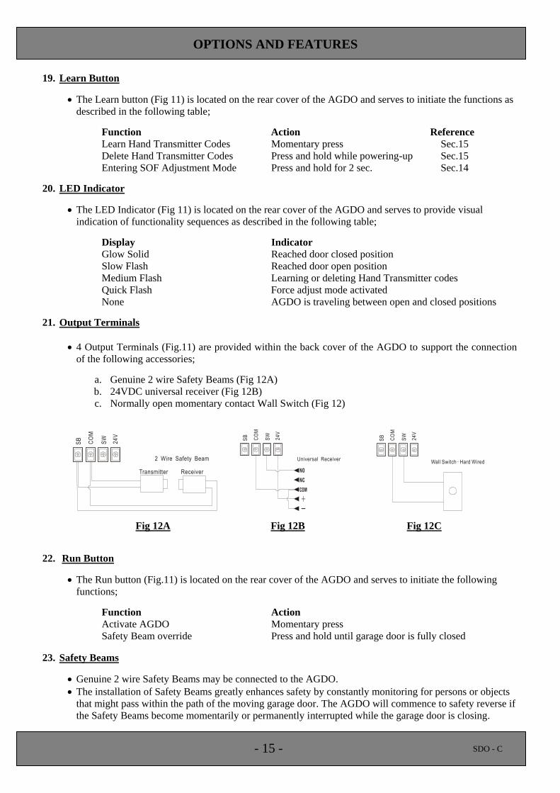
21. Output Terminals
4 Output Terminals (Fig.11) are provided within the back cover of the AGDO to support the connection
of the following accessories;
a. Genuine 2 wire Safety Beams (Fig 12A)
b. 24VDC universal receiver (Fig 12B)
c. Normally open momentary contact Wall Switch (Fig 12)
Fig 12A Fig 12B Fig 12C
22. Run Button
The Run button (Fig.11) is located on the rear cover of the AGDO and serves to initiate the following
functions;
Function Action
Activate AGDO Momentary press
Safety Beam override Press and hold until garage door is fully closed
23. Safety Beams
Genuine 2 wire Safety Beams may be connected to the AGDO.
The installation of Safety Beams greatly enhances safety by constantly monitoring for persons or objects
that might pass within the path of the moving garage door. The AGDO will commence to safety reverse if
the Safety Beams become momentarily or permanently interrupted while the garage door is closing.
- 16 - SDO - C
OPTIONS AND FEATURES
Mounting
Locate the Safety Beam mounting brackets provided.
Mount the bracket so that its bottom edge sits 125mm off the floor.
Use the 2 mounting screws provided to fasten each mounting bracket to the wall.
Use the 2 screws and nuts provided to fasten the 2 Safety Beam modules (“Emitter” and “Receiver”) to
the mounting brackets so that the LED Indicator on each Safety Beam module is facing upwards.
Connection – To Beam Modules
Use the 2 lengths of Figure 8 Cable provided.
Strip back a 15mm length of outer insulator from each of the 4 cable ends.
Connect the cables to the screw terminals of the Safety Beams as depicted in Fig.12A.
Securely fix the cable up and along the wall and run one length of each cable adjacent to the output
terminals of the AGDO. (Fig.11)
Connection – To AGDO
Ensure that the AGDO is switched off.
Strip back a 15mm length of outer insulator from each of the 4 cable ends.
Connect the cables to the Output Terminals “SB” & “SW” located within the rear cover of the AGDO.
(Figs.11 & 12A)
Alignment
Ensure that the AGDO is switched on and that the red LED located along the top edge of the “Emitter”
Safety Beam module is glowing red.
Adjust the “Emitter” Safety Beam module (by turning the mounting bracket) so that it is aimed directly at
the lens of the “Receiver” Safety Beam module. An indicator lamp located along the top edge of the
“Receiver” will glow green once the correct alignment has been achieved.
Test the Safety Beam alignment several times each time ensuring that when the Safety Beams are
obstructed the green LED extinguishes and when unobstructed it glows solid.
Firmly tighten the Safety Beam mounting bracket fixing screws.
Installation of the Safety Beams is now complete.
Enabling
The function select Dip Switches are contained within the rear cover of the AGDO
Select Dip 1 to the “ON” position.
Testing
As the garage door is closing pass an object through the line of the Safety Beams. If the Safety Beams are
functioning correctly the AGDO should stop and then immediately reverse direction.
If the garage door commences a close cycle but within 1 second stops and reverses, check that the Safety
Beams are aligned correctly.
Override
In the event of Safety Beam malfunction the garage door can be closed by pressing and holding the “Run”
button (Fig.11) until such time as the garage door is fully closed and has stopped.
Note: If “Run” button is released prior to the garage door reaching the fully closed position the AGDO
will stop and then reverse direction.
- 17 - SDO - C
OPTIONS AND FEATURES
24. Thermal Overload
In order to prevent overheating damage the AGDO is equipped with an internal thermal overload switch.
In the event of continuous usage the AGDO may overheat and shut down. After a shut down the thermal
overload switch will automatically reset after a 20 ~ 30 minute cooling period.
25. Wall Switch – Hard Wired
A permanently wired Wall Switch may be connected to the AGDO in a convenient location such as
adjacent to a side entry door into the garage.
Use a normally open momentary contact type switch. (similar to spring loaded door bell type switch)
Connect the Wall Switch to the Output Terminals depicted in Fig.12C.
Important Note: The Wall Switch must be mounted within sight of the garage door and a
reasonable distance away from moving parts. It should be mounted at least 1500mm above the
ground and the Entrapment Warning Label provided must be attached adjacent to and within
clear sight of it.
26. Wall Switch – Wireless
The wireless wall switch provides ease of installation without the need for running hard wires to the
switch and can be mounted in a convenient location such as adjacent to a side entry door into the garage.
The Wireless Wall Switch may be learned into the AGDO as per the procedure outlined in Sec.15 (Hand
Transmitter Code Learning)
The switch can be permanently screwed to the wall through the mounting holes provided or alternatively
“hooked” on the wall providing the convenience of easy demount ability.
Use the mounting template and mounting instructions provided with the switch.
Important Note: The wireless Wall Switch must be mounted within sight of the garage door and a
reasonable distance away from moving parts. It should be mounted at least 1500mm above the
ground and the Entrapment Warning Label provided must be attached adjacent to and within
clear sight of it.
TECHNICAL SPECIFICATIONS
INPUT VOLTAGE: 230 ~ 240VAC 50Hz
MAX DOOR HEIGHT: 3600mm using 4200mm rail
MAX DOOR WIDTH: 6500mm
MAX DOOR AREA: 15 Square Meters
MAX LIFTING CAPACITY: Electronically Limited to 400N
MAX No. OF CYCLES TO THERMAL CUT OUT: Approx 10
MOTOR TYPE: ½ HP AC 4 Pole Induction
SAFETY OBSTRUCTION FORCE SYSTEM: Manually Adjustable Trim Pot
DOOR TRAVEL ADJUSTMENT: Manually Adjustable Micro Switch
RECEIVER CODE STORAGE CAPACITY: 13 Individual Transmitters
TRANSMITTER FREQUENCY: 433.92 MHz Hopping Code
LIGHT GLOBE: 60Watt Edison screw rough construction
DOOR TRAVEL SPEED: 125mm/second
AUTO CLOSE: Dip Switch Selectable
PHOTO BEAMS: Optional
Specifications are subject to change without prior notice.

- 18 - SDO - C
TROUBLE SHOOTING GUIDE
Symptom Suggested Remedies Reference
Page Item
• AGDO will not function at all
• Check that AGDO is connected to power supply ~ ~
• Check power point function by plugging-in an alternate appliance ~ ~
• Check that AGDO is engaged to door 11 13
• Disengage AGDO from door and check for obstructions 11 12
• Door stops before reaching • Disengage AGDO from door and check for correct spring balance 4 3
fully open position • Check for correct Safety Obstruction Force settings (open direction) 12 15
• Check for correct open direction travel adjustment 11 14
• Disengage AGDO from door and check for obstructions 11 12
• Door stops & reverses before • Disengage AGDO from door and check for correct spring balance 4 3
reaching fully closed position • Check for correct Safety Obstruction Force settings (close direction) 12 15
• Check for correct Safety Beam alignment 15 24
• Door stops before reaching • Check for correct close direction travel adjustment 11 14
fully closed position
• Door will not Safety Reverse • Contact serviceman ~ ~
• Door requires excessive force • Check for correct Safety Obstruction Force settings (close direction) 12 15
to Safety Reverse
• Door requires excessive force • Check for correct Safety Obstruction Force settings (open direction) 12 15
to Safety Stop
• Check function of AGDO by operating from "Run" button 15 23
• AGDO will not function from • Check function of AGDO by learning-in a substitute Hand Transmitter 13 16
Hand Transmitter • Re learn Hand Transmitter code into AGDO 13 16
• Replace Hand Transmitter battery 13 16
• Hand Transmitter operating • Replace Hand Transmitter battery 13 16
range is poor • Extended AGDO antenna ~ ~
• Courtesy Lamp will not • Replace Courtesy Lamp bulb 14 18
function
• Cannot adjust Safety • Ensure that Safety Obstruction Force Adjustment Mode has been entered 12 15
Obstruction Force settings
• LED Indicator glows solid • AGDO has reached fully closed position 15 21
• LED Indicator slow flashes • AGDO has reached fully open position 15 21
• LED Indicator has extinguished • AGDO is traveling between limits 15 21
• Door will not Auto Close
• Check for Safety Beam damage ~ ~
• Check for correct Safety Beam alignment 15 24
• Check that Dip 1 & 2 have been selected to the "ON" position 14 17
• Check that connecting wires have not come loose from Safety Beams 15 24
• Check that connecting wires have not come loose AGDO terminals 15 24
• Will not Safety Reverse when • Check that Dip 1 has been selected to the "ON" position 15 24
Safety Beams are interrupted
• Door is noisy • Lubricate door springs with automotive wheel bearing grease • Lubricate pivot point of door hinges with WD40
~ ~
• AGDO is noisy
• Check for loose Courtesy Lamp cover is not loose ~ ~
• Check that main cover is not loose ~ ~
• Check that chain is correctly tensioned 7 4

- 19 - SDO - C
NOTES