changes proposed for agricultural aviation
TRANSCRIPT

vectorPointing to Safer aviation
Sept
embe
r / O
ctob
er 2
009
asymmetric flight
Dipsticks
taildraggers 101
Changes Proposed for agricultural aviation

ISSN 1173-9614
In this issue...Changes Proposed for Agricultural Aviation
You can participate in the rule development process. We remind you how to get involved, and mention some of the changes proposed in the soon-to-be released Notice of Proposed Rule Making (NPRM) for Part 137 Agricultural Aircraft Operations.
Taildraggers 101
The short-field performance and prop clearance of many taildragger types make them a logical choice if you are interested in strip flying. Here are a few basics to get your head around before your first lesson.
Asymmetric Flight
Asymmetric flight is an exercise that must be practised regularly. However, in light twins, that practice can be more dangerous that the real life engine failure. Practising must never put the aeroplane in danger.
Dipsticks
The fuel dipstick is a very reliable way to measure the amount of fuel in your aircraft tanks, but it is often a misunderstood tool. Here are some reminders about dipsticks, usable and unusable fuel, and aircraft empty weight.
4
vector
Published byThe Communications and Safety Education Unit of the Civil Aviation Authority of New Zealand, P O Box 31–441, Lower Hutt 5040, New Zealand.
Tel: +64–4–560 9400, Fax: +64–4–569 2024, Email: [email protected]. Published six times a year, in the last week of every odd month.
Manager Communications Bill Sommer.
Editor Peter Singleton.
Safety Education Publishing TeamLakshmi Guda, Cliff Jenks, Anna McClay, Clare Ferguson, Rose Wood.
Design Gusto Design & Print Ltd.
Publication ContentUnless expressly stated as CAA policy, the views expressed in Vector do not necessarily reflect the policy of the Civil Aviation Authority. Articles are intended to stimulate discussion, and nothing in Vector is to be taken as overriding any New Zealand civil aviation legislation, or any statements issued by the Director of Civil Aviation or the Civil Aviation Authority of New Zealand.
Reader comments and contributions are welcome and may be published, but the Editor reserves the right to edit or abridge them, and not to publish those that are judged not to contribute constructively towards safer aviation. Reader contributions and correspondence regarding the content of Vector should be addressed to: Vector Editor, P O Box 31–441, Lower Hutt 5040, or email: [email protected].
Free DistributionVector is distributed automatically to all New Zealand flight crew, air traffic controllers, aircraft maintenance engineer licence holders, aircraft owners, most organisations holding an aviation document, and to certain other persons and organisations interested in promoting safer aviation.
In the case of flight crew and air traffic controllers, a current aviation medical certificate must be held, and a current New Zealand address given, to ensure magazine entitlement.
Holders of Pilot Certificates issued by Part 149 certificated organisations can also apply to receive a free Vector (see the CAA web site for details). Vector also appears on the CAA’s web site: www.caa.govt.nz.
Change of AddressReaders receiving Vector free of charge should notify [email protected] of any change of address, quoting your CAA Client Number. Paying subscribers should notify The Colour Guy.
Paid SubscriptionsVector is available on subscription only from The Colour Guy, P O Box 30–464, Lower Hutt 5040, Freephone 0800–438 785.
CopyrightReproduction in whole or in part of any item in Vector, other than material shown to be from other sources or named authors, is freely permitted, providing that it is intended solely for the purpose of promoting safer aviation, and providing that acknowledgment is given to Vector.
vector September / October 20092
Changes Proposed for Agricultural Aviation 3
Asymmetric Flight 4
Which Runway Are You Going For? 8
Dipsticks 9
Prop Strikes 12
CAA to Relocate in Central Wellington 13
Taildraggers 101 14
Flight Instructor Seminars 17
Airspace Changes 18
Competently Current 20
Aviation Safety Advisers 21
IFIS Met Now MetFlight GA 21
Icing Correction 21
Director’s Awards 22
GPS Equipment Maintenance 23
Flight Training Changes 23
New Products 24
Planning an Aviation Event? 24
How to Get Aviation Publications 24
Accident Briefs 25
What’s New? 26
GA Defects 27
Photo Competition 28
Cover: Ray Patchett, owner and pilot for Omaka based company Patchett Ag Air, is seen here spreading lime on a vineyard in the Awatere Valley with the Gippsland GA200 Fatman. Photo: Gavin Conroy
9
14
4
3

The proposals should have no surprises for those in the industry – they have been discussed at
previous annual conferences, and a project working group of industry participants has been involved in the rule development since March 2008.
John Fogden, CAA Manager Rotary Wing and Agricultural Operations, says, “At the Agricultural Aviation Association (AAA) conference held in Blenheim in July, there was a strong message from the industry itself that the agricultural sector has an unacceptable safety record. The membership was urged to take ownership of the situation, and the CAA
believes the changes proposed to the rule will help them do that. The proposed changes will help create a level playing field, and establish some standards that will assist operators to better manage the safety of their businesses.”
There are a number of proposals in the NPRM, including: certification under Part 137, fatigue management, chief pilot responsibilities, training and super-vision of junior pilots, seat restraints, determination of hopper contents, and the overloading determination in Appendix B.
The agricultural aviation industry curr- ently consists of approximately 112
Changes Proposed for Agricultural AviationA Notice of Proposed Rule Making (NPRM) on amendments to Part 137 Agricultural Aircraft Operations is due to be released soon.
active Part 137 certificated operators, 97 aeroplanes, and 133 helicopters.
To be alerted when the NPRM is published, subscribe to our email notification service, www.caa.govt.nz/subscribe. This notification will include the closing date for submissions.
The NPRM is published so that all interested parties can have their say about the changes proposed. You can find out more about having your say, and the whole process, in our free booklet, The Rule Development Process – just email [email protected] for a copy.
3vector September / October 2009

This emergency happens close to the ground, at low airspeed, at the heaviest point of the whole flight, and asks the remaining engine to operate at its maximum
available power setting. Not a situation to be taken lightly. Add to that the need to accurately control the aeroplane, carry out the emergency actions, and follow the Standard Instru-ment Departure. It makes you tired just thinking about it.
There is a need to practise this, so you are well prepared should you be unlucky enough to face this in real life. Unfortunately, there are more accidents because of simulated EFATO, than because of real EFATO. That does not negate the need for practice – it just illustrates the need for a heightened awareness of the dangers.
The most critical things you lose, when you lose power from one engine, are climb performance and controllability.
Climb PerformanceClimb performance depends on excess power. Loss of power from one engine obviously represents a 50 percent loss of power, but in virtually all light twins, this results in a reduction of climb performance of at least 80 percent (see Figure 1).
The amount of power required for level flight depends on how much drag must be overcome to sustain level flight. Clearly, drag is increased if the gear and flap are down and a prop is windmilling, and more power will be required to overcome this. You may need to reach down into the memory banks, however, to remember that drag also increases as the square of the airspeed, and power required to maintain that speed increases as the cube of the airspeed (see Figure 2).
Climb performance depends on four factors:
Airspeed – too little or too much will decrease climb »performance.
Drag – gear, flap, cowl flap, prop, and speed. »
Power – amount available in excess of that needed for »level flight.
Weight – passengers, baggage, cargo, and fuel load greatly »affect climb performance.
YawImmediately following the failure of one engine, yaw is caused by asymmetric thrust and displacement of the total drag towards the inoperative engine. Yaw forces must be balanced with the rudder (or by reducing power on the operating engine) (see Figure 3).
Loss of power on one engine reduces slipstream (and induced lift) over the wing. Yaw also affects the lift distribution over the wing, causing a roll towards the inoperative engine. These roll forces may be balanced by banking towards the operating engine.
If a small bank angle (about five degrees) is used towards the operating engine to help counteract the yaw, a smaller rudder force will be required. Since the displaced rudder increases drag, any reduction in rudder angle will lessen the drag, and performance will be improved. Think of it as ‘raising the dead’ and then you will remember to raise the wing with the dead engine.
Asymmetric FlightAn engine failure after takeoff (EFATO) will be the most performance-critical manoeuvre in your twin-engine life.
Figure 1. Effect of inoperative engine and aircraft configuration on vertical speed.
Figure 2. Effect of airspeed on drag and power required to maintain that airspeed in level flight.
Vert
ical
spe
ed
Indicated airspeed
0
+
-
Twin-engine climb
One engine inoperative and minimum drag
One engine inoperative, prop windmilling
One engine inoperative, gear and flaps down, prop windmilling
800
700
600
500
400
300
200
100100 110 120 130 140 150 160 170 180 190 200
Airspeed (knots)
Perc
enta
ge o
f inc
reas
e
Drag increases with airspeed
Power require
d to m
aintai
n airsp
ee
d
4 vector September / October 2009

Critical EngineThe critical engine is that engine, which failed, would most adversely affect the performance or handling qualities of the aeroplane. The critical engine on most US-manufactured light twins is the left engine, as its failure requires the most rudder force to overcome yaw.
In level flight, the thrust line of each engine is through the propeller hub. But at low airspeeds and high angles of attack, the effective thrust centreline shifts to the right on each engine, because the down-going propeller blades produce more thrust than the up-going blades (called asymmetric blade effect, asymmetric propeller thrust, or P-factor, see Figure 4). Therefore, the thrust line of the right engine moves further from the centreline of the aircraft (giving a longer lever arm), resulting in greater yaw and more rudder needed to counterbalance the yaw.
Twins with counter-rotating propellers don’t have a critical engine.
Figure 3. Yaw. Figure 4. Engine thrust line shifts to the right at low airspeeds and high angles of attack.
AirspeedAirspeed is the key to safe single-engine operations. There are a few you should be familiar with:
VMCA Minimum control speed airborne.
VSSE Airspeed below which an intentional engine cut should never be made.
VYSE Best single-engine rate of climb speed.
VXSE Best single-engine angle of climb speed.
V1 Decision speed.
V2 Takeoff safety speed.
VMCA – Minimum Control Speed Airborne
VMCA is designated by the red radial on the airspeed indicator, and indicates the minimum speed at which you can still control the aeroplane while airborne, at sea level.
Continued over »Thrust from
operating engine
Counterbalancingforce exerted by
rudder
Direction of yawing tendency
Drag from inoperative
engine
Counterbalancingforce exerted by
rudder
Off-set thrust lines due to “P-factor”
Photo: ©istockphoto.com /Ken Babione
5vector September / October 2009

» Continued from previous page
VMCA is determined by the manufacturer as the minimum airspeed at which it is possible, after a sudden failure of the critical engine, to recover directional control of the aircraft within 20 degrees heading change, and then maintain straight flight with no more than five degrees of bank, in the following configuration:
Takeoff power on both engines. »
Rearmost allowable centre of gravity. »
Flap in takeoff position. »
Landing gear retracted. »
Propeller windmilling in takeoff pitch configuration »(or feathered if automatically feathered).
Sudden engine failures rarely occur in this configuration, however, and therefore the actual VMCA may vary.
For instance, VMCA decreases when the propeller is feathered, or when power on the operative engine is reduced, or when the C of G is forward of the rear limit.
Other factors affecting this minimum control speed include:
Turbulence – which will effectively increase V » MCA because the pilot cannot control the aircraft as precisely as they otherwise might.
The strength and skill of the pilot – we are not all test pilots. »
Pilot seat position – so that full and sustained rudder »deflection is possible.
Practising VMCA
Extreme caution must be used when undertaking minimum control speed exercises. With some aircraft, VMCA occurs below VS at all altitudes. When this is not the case, there is a point where the single-engine power-on stall speed will correspond with the VMCA line (see Figure 5). In this situation, the instructor may need to promote the loss of directional control in order to achieve the practise exercise. In turbocharged aircraft there is generally plenty of power available, which means the exercise can be practised at higher altitudes. With non-turbocharged engines, the power availability diminishes quickly with increasing altitude. Therefore, in order to achieve
VMCA well before the stall onset, the exercise may need to be carried out at a lower level.
Recovery from VMCA should start as soon as the pilot has lost directional control by five degrees, but it is imperative that recovery is made at the first sign of any stall onset. If the yaw coincides with the stall, or soon after, a spin will be the most likely result. Some light twins have not had spin recovery demonstrated, and the likelihood of you recovering would be remote. Consequently, it is not advisable to fly at speeds approaching VMCA, except in training situations or during flight tests, where you have a qualified multi-engine flight instructor with you.
Recovery from flight at or below VMCA is made by reducing power on the operating engine (to stop further yaw), while decreasing the angle of attack by lowering the nose. Immediately following this initial recovery, power is returned to both engines, and the aircraft accelerated back to a safe speed.
VSSE – Intentional One-Engine-Inoperative SpeedVSSE is specified by the aeroplane manufacturer and is the minimum speed you can intentionally fail an engine. The use of VSSE is intended to reduce the potential for an accident arising from loss of control after an engine failure has been simulated at, or near, minimum control speed. VSSE demonstrations are necessary in training but should only be made at a safe altitude above the terrain and with the power reduction on one engine made at, or above, VSSE.
Power on the operating engine should be set at the position for maximum continuous operation as airspeed is reduced slowly (one knot per second), until directional control can no longer be maintained, or there is any indication of stall onset (see Figure 5).
VYSE – Best Single-Engine Rate-of-Climb SpeedVYSE is designated by the blue radial on the airspeed indicator. VYSE delivers the greatest gain in altitude in the shortest possible time, and is based on the following criteria:
Critical engine inoperative, and its propeller in »the minimum drag position.
Operating engine at no more than maximum »continuous power.
Landing gear retracted. »
Wing flap in the most favourable position »(best lift/drag ratio).
Cowl flap as required for engine cooling. »
Aircraft flown at recommended bank angle. »
Drag, caused by a windmilling propeller, extended landing gear, or flap in the landing position, will severely degrade or destroy single-engine climb performance. Single-engine climb performance varies widely with type of aeroplane, weight, temperature, altitude and aeroplane configuration. The rate of climb may be marginal – or even negative – under some conditions. Study the Flight Manual for your specific aeroplane and know what performance to expect with one engine inoperative (OEI). Figure 5. Relationship between stall speed and VMCA (non-turbocharged
engines).
Indicated airspeed
Recovery may be difficult
Stall first
Yaw first
Single engine power-on stall speed
Pres
sure
alti
tude
Vmca
6 vector September / October 2009

It is important to remember that the figures in the Flight Manual cannot be guaranteed. These figures were established in a brand-new aeroplane and in the hands of a test pilot – you may well be unable to reproduce the stated performance. In many light-twin aircraft, there may not be any single-engine climb performance. Don’t bet your life on the book figures.
VXSE – Best Single-Engine Angle-of-Climb SpeedVXSE is used only to clear obstructions during initial climb-out, as it gives the greatest altitude gain per unit of horizontal distance. It provides less engine cooling and requires more rudder than VYSE. Some manufacturers do not quote a VXSE, as performance is marginal – and rarely better than at VYSE.
V1 – Decision SpeedV1 is the maximum speed, for a given length of runway, from which a particular aircraft could be brought to rest in the remaining length of runway after one engine has failed.
V2 – Takeoff Safety SpeedV2 is the lowest speed above the stall, while in the takeoff configuration, and following failure of the critical engine, where a safe margin of control is ensured for the average pilot. The safety speed is therefore always higher than the worst critical speed. Takeoff safety speed is either declared in the Flight Manual or is the greater of 1.2 VS or 1.05 VMCA. Takeoff safety speed does not provide maximum performance.
The next issue of Vector will have an article on the practical aspects of dealing with an EFATO.
It is not advisable to fly at speeds approaching VMCA except in training situations or during flight tests, where you have a qualified multi-engine flight instructor with you.
Photo: ©istockphoto.com / Jeffrey Zavitski
7vector September / October 2009

Which Runway Are You Going For?There seems to be some inconsistency in the way we, as pilots, refer to runways. This is particularly important at aerodromes where there are parallel runways.
Each runway is designated by the aerodrome operator and published in AIP New Zealand,
Vol 4 and pilots should use those designations.
In order to maintain consistency, and to mitigate any human factors related risks, the CAA has been asked to clarify its position on the correct phraseology to use when referring to parallel runways.
Let’s look at a simple example – Wanaka. Here there are two parallel runways of similar length, both designated runway 29. If you are joining for Wanaka, you should be absolutely clear as to which runway you intend to land on. When joining for 29 you should say “joining for 29 seal”, or “joining for 29 grass”. Other examples of this are Woodbourne, Timaru, Motueka, Kaikoura, Hastings, and Dargaville.
Let’s look at another example – Napier. This aerodrome is slightly more critical, as the grass vector crosses taxiways, and there is a mix of light aircraft and turboprop airliners. On initial contact with Napier, Tower or traffic, inform them of your intentions, for example “34 grass” or “34 seal”. The exception would be, however, those airlines that always use the seal. They do not need to specify the seal to the Tower – that
will be considered normal operations. This would equally apply at Tauranga, Hamilton, New Plymouth, Gisborne, and Rotorua.
Let’s look at a slightly more complicated example – Wanganui. There are three parallel runways, 29L, 29, and 29R. 29L and 29R are the grass vectors, and 29 is the sealed vector. If you are joining for one of the grass vectors you could add “grass” to the designator, for example “29L grass”. To ensure consistency through-out the country, wherever there is a parallel runway, when joining the sealed runway, you should say “joining for 29 seal”.
Now let’s look at the exceptions. Take Queenstown for example. If you are flying a large aircraft intending to land on runway 23, there will be absolutely no need to request “23 seal”. However, if you are a light aircraft, you need to be completely clear, so the controller is also clear, which vector you intend to land on. You should request either “23 grass”, or “23 seal”. The same would apply at Christ-church and Invercargill.
Hopefully, this has cleared up any confusion. If in doubt, add either “grass” or “seal” and then it will be completely unam-biguous.
Photo: ©istockphoto.com/ Maciej Noskowski
8 vector September / October 2009

The fuel dipstick is a very reliable way to measure the amount of fuel in your aircraft tanks, but it is often
a misunderstood tool.
Unusable FuelThe quantity of unusable fuel is determined during the original aircraft certification process. Usually, this involves a test to find out how much fuel remains in the tanks at the point at which the engine fuel supply is interrupted. Federal Aviation Regulation 23.959(a) says that the unusable fuel supply for each tank must be established as not less than the quantity at which the first evidence of malfunctioning occurs under the most adverse fuel feed condition occurring under each intended operation and flight manoeuvre. For conventional aircraft with a forward mounted engine, this is usually nose up at best angle of climb attitude.
The amount of unusable fuel can vary considerably from aircraft to aircraft. There is a big difference between Piper and Cessna aircraft, for example.
The Flight Manual should show the unusable fuel quantity.
Continued over »
Two long-standing problems have been identified in relation to dipsticks and usable/unusable fuel: there are no set standards for dipsticks, and there can be
variations in the way engineers take account of unusable fuel in calculating empty weight.
A look around the GA fleet at any aerodrome is most likely to reveal a variety of home-made dipsticks, calibrated in different ways. It is rare to find a dipstick made by the manufacturer for a particular aircraft.
Here are some points regarded as best practice for dipsticks:
Dipsticks should be made up by licensed engineers »
The dipstick should be specific to a particular aircraft, »and have the registration letters on it
It should be made of a non-absorbent material that will »show the fuel level
It should not be able to fall into the tank (usually achieved »with length, or a T-cross)
The zero calibration should be the point where » usable fuel starts
It should be calibrated in litres. »
If using an existing dipstick, you must know if it is reading usable fuel (recommended) or total fuel. If it reads total fuel, you will need to know the aircraft’s unusable fuel quantity. This can be found in the Flight Manual.
Usable FuelUsable fuel is the quantity of fuel available for flight planning purposes – it is the only figure that should be used when calculating fuel endurance. If the dipstick indicates total tank quantity you must subtract the unusable fuel quantity to arrive at usable fuel for calculating endurance.
Some aircraft have a placard showing the usable fuel quantity near the filler cap.
Dipsticks
9vector September / October 2009

Aircraft Empty WeightEmpty weight is the weight of an aircraft, including airframe, powerplant(s), all fixed equipment, full oil tank(s), and unusable fuel. The empty weight figure is found in the form CAA2173 located in the Flight Manual and can be expressed in pounds or kilograms. On the back of the form is listed all the equipment fitted at the time the aircraft was weighed.
Engineers preparing the CAA2173 form need to adhere to the manufacturers’ procedure for determining unusable fuel. This varies from type to type. For example, some manufacturers will use a method that runs the engine until it stops, and then add a specified quantity, whereas other manufacturers may say to drain the tanks entirely, and add a specified amount. The resulting level may be above the fuel outlet port to allow for the manoeuvres described above (see diagram).
For more information see our booklet, Weight and Balance, and Advisory Circular AC43-2 Aircraft weight and balance control – forms CAA2102 and CAA2173.
Role of the Fuel GaugesContrary to some opinion, most fuel gauges do read reason-ably accurately. After dipping the tanks, check the gauges and compare the readings – you will then know if the gauges are reading accurately. If they don’t, they need to be repaired.
The fuel gauges should be an integral part of your fuel management. Monitor levels during flight, and compare with your calculations. Fuel loss in flight can happen – through fuel venting, for instance, or a leaking fuel drain. This may not be visible, especially in a low-wing aircraft, so the fuel gauges may be your only clue that fuel is being used at a greater rate than planned.
Tips for Dipping Your TanksHere are some points that should be kept in mind when dipping a fuel tank:
The aircraft should be parked on level ground. If this is »not possible, dip each tank, turn the aircraft through 180 degrees, dip each tank again, and take the average of the two values. This may not be totally accurate, but it will be better than either of the two single readings.
Cross-feeding during refuelling, or at any other time, can be »prevented in most single-engine aircraft by selecting either the LEFT or RIGHT tank only. The trap here is that when you are refuelling the aircraft with the fuel selector set to BOTH, the tank that you are filling can be cross-feeding to the other tank. Although not large, this could result in a quantity of fuel less than was originally intended in the first tank by the time you have finishing filling the second tank, and this could be a problem if the flight requires both tanks to be full.
Fuel tanks should always be dipped after refuelling to »establish the exact amount of fuel on board – even when adding a known quantity of fuel.
The dipstick should be inserted in the filler neck perpen- »dicular to the wing surface, unless there is another method specified in the Flight Manual. Some aircraft fuel tanks must be dipped on an angle because the main spar is directly below the filler neck.
Always take a fuel sample from each drain point after »refuelling, to check for correct fuel grade and any impurities.
For more information, see our booklet Fuel Management. You can get a free copy by emailing [email protected].
Usable fuel
Un-drainable fuel
Fuel drain point
To engine
Fuel outlet port
Unusable fuel quantity as stated in the Flight Manual
Cross-section of an aircraft fuel tank (not to scale)
» Continued from previous page
10 vector September / October 2009

Contaminated FuelContaminants (especially water) in fuel have been known to cause engine failures – usually just after the aircraft has become airborne. There have been instances when fuel from jerry cans that had been contaminated with water was used in aircraft operations, with disastrous results. The pilots involved were simply unable to tell by looking at the sample that the fuel was contaminated.
Here are some tips to check for contaminants in fuels:
After refuelling, allow the fuel to »settle for as long as possible. This gives any impurities a chance to settle into the drain sump of each tank. At an intermediate stop, it is a good idea to refuel the aircraft first, before attending to other business – this will normally allow enough time for any water in suspension to settle out.
Water often collects in wrinkles and »low points within fuel bladders. Lateral shaking of the aircraft wing will help to work any trapped water down to the fuel drain sumps.
Allow the fuel time to settle after doing this before taking a fuel sample.
Ensure that the drain vessel is clean »before taking a sample. Hold the sample to the light and inspect it for water (normally indicated by small globules sitting on the bottom, or a ‘cloudy’ appearance), and sediment. Check that it is the correct colour and smell for the intended grade of fuel – this will also confirm that you have not just drained a sample of pure water.
If the sample is contaminated, empty »the vessel and continue draining until a clean sample is obtained.
Do not tip the sample back into »the aircraft tank, even if it is clean – dispose of it in an appropriate manner.
If there are unusually large quantities »of water present in the fuel, consult an aircraft engineer.
In cold winter conditions, small »amounts of water can freeze the drain plug, rendering it inoperative.
Fuel tester, showing water that has settled at the bottom (holding it against the white surface helps to show the fuel colour and any water present).
Flight Instructor Jonathan McKay of the Wellington Aero Club looks at the fuel readings on the aircraft’s dipstick.
11vector September / October 2009

Prop StrikesEngine and propeller manufacturers are quite clear about what constitutes a prop strike and what maintenance is then required.
A bent propeller that can be repaired.
Cracking of the crankshaft after impact damage, shown up by fluorescent light during magnetic particle crack testing.
Bends are measured in degrees over a two inch length using a protractor.
Textron Lycoming defines a prop strike in its Service Bulletin 533A as, “Any incident during engine operation in which the propeller impacts a solid object which
causes a drop in RPM and also requires structural repair of the propeller (incidents requiring only paint touch up are not included). This is not restricted to propeller strikes against the ground, and although the propeller may continue to rotate, damage to the engine may result, possibly progressing to engine failure.
“Textron Lycoming must take the position that in the case of a ... propeller/rotor strike ... the safest procedure is to remove and disassemble the engine and completely inspect the reciprocating and rotating parts including crankshaft gear and dowel parts. Any decision to operate an engine which was involved in a ... propeller/rotor strike ... without such an inspection must be the responsibility of the agency returning the aircraft to service.”
Therein lies the heart of the matter. As an engineer you are responsible for returning the aircraft to service. If you do not get the inspection done, what acceptable data are you basing the return to service decision on?
Even if no drop in engine rpm was seen – it’s unlikely the pilot’s attention was on the rpm gauge when hearing loud crunching noises from the propeller – there could still be significant damage to the engine.
Alan Hockey of Flightline Aviation Dunedin says, “There doesn’t seem to be any pattern to the damage to the engine when compared to the damage the prop has sustained. I have seen propellers that seem to have minor damage, but the engine attached to them has a broken crank-shaft. Like the aircraft that hit a hidden airfield marker board.”
The Prop Shop at Safe Air stresses that you cannot just straighten the prop out and continue on flying. You have no idea what damage has been done without a proper inspection.
If the fear of the cost is making your aircraft owner nervous, they need to realise that this cost is usually covered by the insurance policy, and the cost of not doing it may be much higher if they suffer an in-flight engine failure.
The inspection of the engine must be carried out by an appropriately approved Part 145 Maintenance Organisation and includes a complete dismantling of the engine, inspection of all rotating components and engine-driven accessories, replacement of particular parts (such as connecting rods
and nuts, and anything specified in the Replacement of Mandatory Parts Bulletin) and probably some non-
destructive testing.
Propeller testing and overhaul must be completed by an approved maintenance provider.
12 vector September / October 2009

It will occupy one-and-a-half floors of a commercial office block, still under construction, directly opposite
Wellington’s Railway Station. The only other tenants in the 15-storey building will be the Inland Revenue Department and the Aviation Security Service.
The CAA currently occupies two buildings in Petone, of which one is a converted warehouse. Neither is suitable for the CAA’s long-term requirements.
The expiry of the lease on the two buildings provided an opportunity to consider relocation and the CAA started a project in 2007, engaging specialist advice to evaluate the relocation opportunities. The project considered the CAA’s projected space and resource requirements in the next 15 to 20 years, as well as the need to be more accessible to the aviation industry and closer to other transport sector agencies.
CAA to Relocate in Central WellingtonThe CAA is to relocate from Petone, Lower Hutt to central Wellington in February 2011.
Director of Civil Aviation Steve Douglas says the process was thorough and all options were carefully examined.
“The CAA’s Board has been fully involved since the project began in 2007. The relocation and the funding arrangements were approved by the Board with the support of the Government in 2008.”
The CAA has conservatively estimated the one-off costs of the move will be $6.7 million, and will be funded from the CAA’s reserves and cash flow.
Steve Douglas says the move to Wellington is a positive development that is in the long-term interests of the CAA and the function it serves.
“We set about finding office space that addressed feedback we had received from industry, and to meet our current and future requirements. The building
that we will move to is modern in design, with good energy efficiency design characteristics. Our people will have a good working environment, and be located close to public transport.
“And as those who have a longer history with the CAA will remember, this will be a return to central Wellington for the CAA. The organisation moved from central Wellington to Lower Hutt in 1988.”
Beehive
Lambton Q
uay
Lambton Quay
Whitm
ore StBallance St
Stout St
Feat
hers
ton
St
Wat
erlo
o Q
uay
Feat
hers
ton
St
Bunny St
Bunny St
Wellington Railway Station
CAA
13vector September / October 2009

Taildraggers 101
Figure 1. Directional instability of a taildragger.Why not make this dream a reality by learning to fly a taildragger? The short-field performance and prop clearance of many taildragger types make them a logical choice (but not the only choice) if you are
interested in strip flying.
Here are a few basics to get your head around before your first lesson.
On the GroundTaxiing successfully requires your full attention at all times. In addition to using your feet quickly and purposefully, instructor Paul MacDonald tells students transitioning from flying a nose wheel aeroplane, to the C185, “Don’t be afraid to use power and brake at times, always position your ailerons in the correct sense for the wind direction, and catch things early.”
Taildraggers act as a weather vane, and turn into wind naturally. A turn in that direction is simple, but turning downwind can be very hard. In strong winds you will need appropriate use of rudder, brake, and power. Power will increase the air flow across the rudder, making it more effective.
Watch the nose direction at all times and concentrate on keeping it straight. Anticipate any movement of the nose and use positive rudder inputs to control it. It is important to be proactive, because once a taildragger starts to turn, they tend to continue turning. This characteristic is related to the C of G position. A taildragger’s C of G is behind the main gear, to stop it tipping on its nose. If a taildragger taxis in a straight line and then turns left (as in Figure 1), the C of G becomes positioned behind the right main wheel. Due to momentum, the C of G continues moving along its original path, which is straight ahead. This continues the turn by pushing against the outside wheel.
When you press the rudder pedal in a taildragger, there will be a slight delay between applying the pressure and seeing movement. Once the nose is moving, it will continue to move whether the pedal is pressed or not, so rudder is only used to initiate movements, not held in while turning. You will then need to
You take off, accompanied by friends and a picnic basket full of delectable treats. You fly over some of New Zealand’s most incredible scenery, and land on a remote strip. You while away the afternoon in a beautiful spot. Then the alarm clock goes off…
Main wheels
Tail wheel
CG
Aircraft momentum
14 vector September / October 2009

Continued over »
Figure 2. Lift forces on takeoff.
apply rudder with your other foot to stop the nose where you
want it. The amount of rudder required is inversely proportional
to your speed. The faster you are moving, the less rudder you
need for directional control.
The degree of difficulty you will have in controlling a taildragger
is directly related to your ability to see slight movements of
the nose and correct for them. Tiny movements need tiny
corrections – let big movements develop and you will need
big corrections, or potentially loose directional control.
It will take new taildragger pilots time to get used to the
restricted visibility over the nose. Slowly S-turning along the
taxiway will give you the ability to look for other traffic and see
where you are going.
Lift Forces on TakeoffIn Figure 2, you will see that the horizontal tail surfaces on the trike produce a downward force to raise the nosewheel. This ‘negative lift’ effectively adds weight to the aeroplane and requires the wing to produce additional lift for takeoff. By comparison, the horizontal tail surfaces on a taildragger produce an upward force (positive lift) to raise the tail. Since the tailplane supports some aircraft weight, the wing does not have to produce as much additional lift to get the aeroplane off the ground.
Takeoff techniques vary between types and between instructors. Many higher performance aeroplanes (such as the Pitts Special) start the takeoff roll with the stick hard back until there is plenty of airflow over the rudder, then raise the tail. Whereas some slower taildraggers begin the takeoff roll with the stick hard forward so the tail comes up as soon as it has enough speed.
In either case, here are a couple of issues to be aware of. Any time the propeller disc moves its plane of rotation, gyroscopic forces occur. Raising the tail too abruptly on takeoff (by forcefully pushing the stick forward), will cause the propeller to precess, and the aeroplane to turn left. Always use positive rudder inputs to keep the aeroplane straight, do not let it start to turn in the first place.
Raising the tail too high during takeoff will set the wing at a negative angle of attack and drive the main landing gear harder onto the ground. The increased tyre friction created, along with the additional drag produced by such a tail-high attitude, will reduce your acceleration considerably. It can even prevent some low-powered taildraggers, at a high density altitude, from ever reaching liftoff speed.
Lift forces of the tail surfaces in nosewheel vs tailwheel aircraft.
15vector September / October 2009

» Continued from previous page
Figure 3. Bounce on touchdown.
Paul MacDonald explains to his students, “On takeoff, slight forward pressure is needed to get the tail up and flying, then ease back gently to lift off. Since the Cessna 185 naturally lifts off at around 35 or 40 knots, you may need forward pressure after liftoff to accelerate to a safe speed – depending on the trim setting.” Your instructor will show you what the appropriate takeoff trim settings are for the type of aircraft you are flying.
LandingThe key to a successful landing in a taildragger is to touch down straight, at the appropriate speed and attitude for the type of landing you have opted for.
A bounce is the result of a pilot error; a factor of landing speed and rate of descent. The C of G location in a taildragger (behind the main gear) contributes towards their propensity to bounce, but a pilot cannot shift the blame for a bounce onto the aircraft design. If the aeroplane is landed in the appropriate wheeler or three-point attitude, at the appropriate speed, a bounce will not occur.
The aeroplane in Figure 3 has been allowed to touch down prematurely, and the tailwheel is still off the ground. If the touchdown occurs with any significant sink rate, the momentum of the C of G tends to push the tail further down. In the process, the nose rises, increasing the wing’s angle of attack. As a result, additional lift is produced, causing an involuntary liftoff. Newton’s third law also applies. For every action there is an equal and opposite reaction, so the ground ‘pushes back’.
If the tail wheel touches simultaneously with the main gear, however, or slightly earlier, the angle of attack cannot be made to increase providing the aircraft is virtually stalled when in the three-point attitude, resulting in a minimal touchdown speed.
New taildragger pilots often look out the side window as the aeroplane settles on the ground. This makes it difficult to judge if you are rolling straight or not. Instead, look straight ahead and use your peripheral vision to look at both sides of the runway at once. This will make minor movements of the nose easier to detect, and a quicker response possible.
A ‘wheel landing’ can be more difficult to perform. It is executed in a near-level attitude by literally flying the main wheels onto the runway. The pilot has better visibility during a wheel landing due to the aircraft attitude, and when it is gusty, a wheel landing allows you to maintain control right down to the runway.
In most taildraggers, it is possible to nose over during touch-down, but flying a stable approach profile, using the correct technique for the landing type, maintaining speed control, and immediate directional control, will avoid this. It is also possible to nose over when taxiing with a tailwind, or turning – but this
would usually require either full forward or back elevator pressure, heavy braking, or a combination of these with power. The key to avoiding this is understanding the effects of C of G position and the wind, taxiing slowly with your controls in the appropriate position, and smoothly applying brake.
Ground loops after landing are usually caused by losing direc-tional control through inattention. They happen when yaw is not anticipated, and then assertive rudder inputs are not made to firstly stop the turn continuing, and secondly bring the nose back parallel with the centerline. When the nose begins to swerve, unless it is caught, it continues to yaw with a progressively shorter turning radius. As the arc made by the aircraft begins to spiral inward, the rate of turn also increases. Simultaneously, centrifugal force increases, and unless this is interrupted, the aircraft ultimately loses balance and topples toward the outside wing. Anticipation is essential. If you wait until the nose swerves, and then try to correct it, it is too late. Paul MacDonald says, “After landing, keep your feet working and steer straight away – don’t go to sleep once you are on the ground.”
Ground loops are not that difficult to avoid. Just remember that a taildragger landing is not complete until the aircraft is parked – don’t think your job is done after a successful touchdown.
Learning to fly a taildragger is not necessarily more difficult than learning to fly a trike. They are just less tolerant of errors made along the way.
Specialist taildragger instructor, Kerry Conner, says, “the challenge of flying a taildragger is controlling and handling it correctly on the ground.
“When a new taildragger pilot has mastered the three-point landing, and their confidence is building, their concentration drops off, they get a wind gust, and bam – they are off the runway or facing 180 degrees to the landing direction. After this lesson, it is time to move on to wheel landings – no wind at first, to get the technique mastered, and once that is under control I take them out in a crosswind. Students start by learning the three-point crosswind, then a wheel crosswind, which eventually has them landing on one wheel.
“Once they have mastered the three, two, and one wheel landings on a sealed runway, a new taildragger pilot is ready to fly solo.
“Throw in the short landing technique and you can have five or six different types of landings with which to test your piloting skills. Flying a taildragger is a test of a pilot’s situational aware-ness of wind when determining landing type, making the correct decision, and being able to execute the chosen landing while keeping both pride and aircraft intact,” says Kerry.
If you do take up the challenge, make sure you learn with an instructor who is experienced on type.
MomentumAngle of attack increases
CG
Photo courtesy of Craig Hayden
16 vector September / October 2009

“We deliberately hold the seminars away from the main centres because it’s important for them to get together and find out that they have the same problems as each other. It can feel pretty isolated, working away in a small aero club on your own, and we want to send the message that instructing counts,” says John Parker, CAA Flight Examiner.
This year’s theme was changes – what changes have recently occurred, what is coming up, and how to deal with change.
Day one saw Rex Kenny, CAA Manager Sport and Recreation and prolific amateur aircraft constructor, give a presentation on the future use of Light Sport Aircraft for flight instruction.
ASL gave a presentation on the changes to examinations, particularly the intro-duction of computer-based exams.
Peter Wheeler, CTC Aviation Hamilton, gave a presentation on the changing face of avionics and new GPS technologies available in GA aircraft. There is some very high-tech gear available for light aircraft.
Brendan Bourne, CAA Aviation Examiner and experienced A-Cat, talked about the responsibilities you take on as an instructor. How your attitude and professionalism, especially as a C-Cat
affects your student’s attitude and perception of flying.
Mark Price, CAA Examiner AME and very experienced maintenance engineer, emphasised that as pilot-in-command you are the final decision maker when it comes to determining if the aircraft is airworthy. He then talked about what is airworthy and what is not.
John Parker, organiser of this event, spoke about threat and error manage-ment. He encouraged instructors to become familiar with this approach, as they will see more of this in general aviation, not just in the airlines.
Airways gave a presentation on radar air traffic control, using a radar screen replay to show how air traffic controllers maintain separation and traffic flow in a busy radar environment.
Carlton Campbell, CAA Training Standards Development Officer, A-Cat, and experienced mountain flyer, gave a heads up on the terrain and weather training being introduced into the PPL and CPL syllabuses, and how that training is being rolled out. He also alerted instructors to the current development by the CAA of a new mountain flying DVD, and the topic of next year’s AvKiwi Safety Seminars.
Flight Instructor SeminarsThe recent flight instructor seminars held in Masterton, Hamilton, and Ashburton were a great success, with approximately 130 instructors attending. The prime objectives were to give instructors the opportunity to network and to give them direct access to CAA expertise.
Day one was finished off by Rachel Donald giving a presentation on Spider-tracks – the New Zealand developed flight following technology.
Day two started with Dr Claude Preitner, CAA Senior Medical Officer, and pilot, talking on life changes, particularly the aging process, and the Recreational Pilot Licence.
The rest of the day was an instructional techniques refresher by Kaye Sutherland of Air New Zealand.
Jeremy Anderson of Nelson Aviation College says, “I enjoyed it immensely. It was the first time I have been, but I am really keen to get to the next one. Probably the best thing about the seminar was the ability to talk to other instructors and to the CAA directly. Now that doesn’t mean that the sessions weren’t good – they were, some of them were great, especially the ones on air-worthiness and your job as an instructor, and the one from the doctor.”
Steve McNabb, of Helipro in Paraparaumu added, “I thoroughly enjoyed it, and I didn’t really expect to. The networking was important, but for me, I really enjoyed the stuff on Spidertracks, mountain flying, and the instructional techniques refresher.” Ph
oto
cour
tesy
of C
essn
a Ai
rcra
ft Co
mpa
ny
17vector September / October 2009

There are two main outcomes from the 2009 airspace review process. VFR aircraft will have increased
access to portions of controlled air-space, either by the establishment of VFR transit lanes, or by the removal of controlled airspace entirely. Where controlled airspace is not used by IFR aircraft, it has been released to improve
the safe and efficient flow of VFR traffic. This will reduce the number of circuitous tracks flown to avoid controlled air-space, and also reduce controller workload. Always operate your trans-ponder on mode A and C, to provide added safety assurance when operating near controlled airspace boundaries, especially within VFR transit lanes.
Airspace ChangesThis year’s round of airspace changes will come into effect 19 November 2009, to coincide with new Visual Navigation Charts. Here is a summary of the main changes. It is not exhaustive – pilots should familiarise themselves with all the changes published in AIP Supplements 134/09, 135/09 and 136/09.
The second outcome is an increased number of Common Frequency Zones (CFZs). CFZs are designed to improve safety by establishing a single frequency to assist collision avoidance, and reduce congestion on 119.1 MHz. Use of the CFZ frequency is not mandatory.
OLD NEW
OLD NEW
HAMILTON
WOODBOURNE
18 vector September / October 2009

AIXM DatabaseThe CAA provides an Aeronautical Infor-mation Service (AIS) comprising the AIP New Zealand, aeronautical charts, NOTAM and pre-flight briefing services. Airways Corporation are contracted to provide this service. The CAA also provides a legal description of airspace,
and the geographical coordinates of designated points and other significant locations contained in the New Zealand Air Navigation Register (ANR).
The data for the various AIS prod-ucts and the ANR resides in many separate databases. Currently, human processing is involved at several key stages of AIS production. Information is submitted for the AIP in paper format, then manually processed to produce a paper format AIP New Zealand. All users manually enter the data into their systems, and the CAA manually updates the ANR.
This is in the process of changing. The CAA and Airways are devel-oping an Aeronautical Information eXchange Model (AIXM) database to serve as the single source of national aeronautical information. This move is in line with develop-ments in the rest of the world, and will use an ICAO recognised format to reduce the need to manually manipulate data. Once all aerodrome, heliport, airspace, navaid, obstruction, instrument procedure, route, and significant point data has been entered into the database, and verified, it can then be transferred electronically to users.
Benefits:
A single source database for aero- »nautical data.
» Paper based products will be generated directly from the AIXM data
with minimum manual intervention.
» Aeronautical data will be available to the aviation community in an electronic
format.
The AIXM is currently being populated with existing data. Over the next two years the
AIP New Zeland and the ANR will begin to be produced out of the AIXM database, going ‘live’ once the products are fully tested.
AucklandThe collision avoidance frequency for aircraft transiting between the Auckland City MBZ and the Ardmore MBZ has been clarified with the establishment of a new Ardmore CFZ using 118.1 MHz. Adjacent MBZ and CFZ boundaries have been adjusted in accordance with feedback from airspace users.
A new Coromandel CFZ has been established between the Great Barrier, Ardmore and Bay of Plenty areas. As a consequence, the following aero- dromes will change to 124.5 MHz on 19 November 2009: Coromandel, Great Mercury, Matarangi, Pauanui Beach, Thames, Waihi Beach, and Whitianga.
WaikatoTwo new VFR transit lanes have been established within the Hamilton control zone. The Northern VFR transit lane (NZT 251) will allow aircraft operating by day to transit from the north to the east, below 1000 feet amsl, without the need to contact ATC. Even though the transit lanes have been designed to be well clear of IFR procedures, pilots need to carefully identify the new transit lane boundaries so they do not infringe controlled airspace. The landscape within the transit lane has relatively few prominent features. To assist pilots, a railway/road intersection and major roads have been used as the transit lane boundaries.
The Northern VFR transit lane has also been merged with the Hospital VFR transit lane to allow helicopters to freely arrive and depart from the Hospital Heliport by day. Fixed wing pilots should note that the rule 91.311 requirement to maintain 1000 feet above built up areas means it is not possible for them to use the portion of the VFR transit lane above Hamilton City.
The new Te Awamutu VFR transit lane to the south will allow VFR aircraft to operate freely south of Lake Ngaroto, below 1000 feet amsl, by day.
TaupoAt the request of airspace users, the Taupo MBZ has been extended to the east. The transponder mandatory portion of the MBZ has been lowered to 2500 feet amsl. The Centennial Park CFZ has been also extended and its upper limit raised to 4500 feet amsl to better reflect the normal operating area of gliders near Centennial Park Aerodrome.
WellingtonThe Paraparaumu MBZ has been extended offshore, while onshore portions of the MBZ have been reduced. The MBZ will become transponder mandatory from 1500 feet amsl and above. To the East of the MBZ, a new Tararua CFZ has been established on the same frequency as Paraparaumu.
Within the Wellington control zone, new sectors have been established to allow safer transit of VFR aircraft above the new wind turbines west of Wellington.
TasmanThe Nelson VFR transit lanes have been expanded and merged. The MBZ at Motueka has been enlarged at user request, and a new Motueka CFZ has been established adjacent to the MBZ, on the same frequency.
Woodbourne airspace has had major changes to allow VFR aircraft to operate to and from Omaka aero-drome, by day, without an ATC clearance. This will significantly reduce Woodbourne Tower’s workload. How-ever, as Omaka is very close to the extended centreline for Woodbourne Aerodrome’s runways, it is essential that Omaka traffic respect and comply with the strict limits of the new Omaka VFR transit lane. The Waihopai and Ponds VFR transit lanes will be disestablished as a result.
Within the Omaka VFR transit lane, pilots must not cross New Renwick Road unless they receive an ATC clearance to do so (this road was the northern boundary of the disestablished Fairhall Sector).
To the south and west of Woodbourne, a large portion of control area (CTA) has been disestablished in order to allow gliding operations to take place in class G airspace in this area.
CanterburyA new Rangiora CFZ has been established, so the frequency of Rangiora Aerodrome will change to 120.2 MHz. The Canterbury CFZ has had a consequential boundary amendment.
19vector September / October 2009

Competently Current
The bare minimum required to be legally current is far from ideal, and it could leave you floundering in an unexpected or emergency situation.
In flying, as in any other endeavour in life, the rewards and satisfaction achieved are proportional to the effort put in. Are you happy to be a ‘bare minimum’ pilot, or would you rather be thought of as a careful and competent pilot others are happy to go flying with.
CurrencyYou progressively lose your touch the longer you go without flying. The longer the break, the less current, competent, and confident you become.
There are legal minimum requirements to be able to exercise the privileges of your licence, including recent experience requirements. But these may not be enough to be truly current.
Currency is not just the number of flying hours and takeoffs and landings you have completed in the last 90 days – it’s a measure of your readiness to undertake a particular exercise without significant risk.
You are the best person to be able to judge if you are current enough to do a particular flight or task. To allow for things you hadn’t planned on, you must be prepared to a higher standard than may prove necessary on any particular flight.
How to Improve Currency
In Your AircraftDecide what flying you really need. Money seems to have stopped growing on trees, so tailor your flying to best prepare you for the type of flying you do.
If you are an infrequent flyer, collecting type ratings may be fun, but is it the safest option for maintaining an adequate currency level? Sticking to one type may help you feel more confident, and your flying will be safer and enjoyable.
Unless you are employed as a pilot it can be hard to stay current – and even then you may need a top-up from time to time. Current shouldn’t just mean legally current, it should mean competently current.
20 vector September / October 2009
IFIS Met Now MetFlight GAFrom 1 September 2009, preflight weather information was removed from the Airways IFIS web site, with users being redirected to the MetFlight GA web site. This site, sponsored by the CAA, has extensive preflight weather information for private operations. MetService advises that commercial operators should continue to use the MetFlight Commercial or MetJet services.
http://metflight.metra.co.nz
Aviation Safety AdvisersRoss St George has retired from the CAA, so clients in the lower North Island should now contact Don Waters.
Don Waters(North Island)Tel: 0–7–376 9342 Fax: 0–7–376 9350Mobile: 027–485 2096Email: [email protected]
Murray Fowler(South Island)Tel: 0–3–349 8687 Fax: 0–3–349 5851Mobile: 027–485 2098Email: [email protected]
John Keyzer(Maintenance, North Island)Tel: 0–9–267 8063 Fax: 0–9–267 8063Mobile: 027–213 0507Email: [email protected]
Bob Jelley(Maintenance, South Island)Tel: 0–3–322 6388 Fax: 0–3–322 6379Mobile: 027–285 2022Email: [email protected]
Icing CorrectionIn the May/June 2009 issue of Vector in the article, “Icing”, we falsely accused the tailplane of providing a nose-down force. Obviously, it does not provide a nose-down force, but a nose-up force, countering the aircraft’s nose-down tendency. When the tailplane stalls that nose-up force is removed, and the aircraft pitches nose-down. We apologise for this error.
When you do fly, don’t just plod along with your mind in neutral. Discipline yourself to fly accurately – on speed, on altitude, correct power setting, and following procedures precisely. Consider possible emergency situations while you are flying – ask yourself the question all instructors ask you, what would you do now if the engine failed? What would I do now if I had an alternator failure? What would I do now if the destination weather deteriorated below my minimums?
Add variety. Don’t just stick with taking your friends for local scenic flights – get out on your own and practise stalls, steep turns, forced landings, and accurate circuits in a variety of conditions. Programme a flight with an instructor every now and then – don’t just wait until your BFR is due.
In Your ArmchairArmchair flying is practically free – even the professionals do it. Every airline pilot spends time armchair flying their emergency procedures. You improve your ability to react appropriately to in-flight emergencies when you visualize a situation and work through it, step by step in your mind.
An in-flight emergency could happen on your next flight – would you be ready?
Next time your planned flight is cancelled, use that time by sitting in the aircraft and practising checks, emergency procedures, and radio calls. Now what about an engine failure after takeoff, what are the drills? Close your eyes and put your hands where they would go while carrying out the checks.
Why not get out the Flight Manual and revise weight and balance problems, or remind yourself how to use the performance graphs. Pick up a CAA Good Aviation Practice (GAP) booklet and refresh your knowledge.
Sitting around the club sharing stories with other pilots is not just a great way to while away a bad-weather day. It is in fact a great way to learn from other’s experiences. It is much easier to remember a story than a bunch of facts and figures.
Refresher TrainingAfter any break from flying it is a good idea to take some refresher training. Most training organizations have rules requiring a dual check with an instructor after a specified lapse of time from flying. Be clear about what you want to practise and what standard you would like to achieve.
Pilots flying regularly should also undergo refresher training, particularly in emergency procedures. We hope you never need those skills, but if and when you do, they had better be spot on.
Photo: ©istockphoto.com/ Dane Wirtzfeld
21vector September / October 2009

Every year the Director of Civil Aviation presents awards to members of the industry who
have shown a commitment to safety well above the norm. This year the Individual award winner was John Martin, Head of Safety Programmes at Air Nelson. The Flight Instructor Award was won by Richard Desborough, Standards Pilot at The Helicopter Line.
John MartinJohn is the Head of Safety Programmes at Air Nelson, and he has done an outstanding job to raise safety aware-ness among crew and management alike. In his own time he produces Air Nelson’s top class safety magazine, Safety Link, which is widely distributed locally and internationally.
His recent achievements include facili-tating an RNAV Human Factors review conducted by Cranfield University, and is currently tasked with managing a Line Operations Safety Audit (LOSA).
Director’s AwardsHe recently presented a paper on the Human Factors surrounding the FMS/RNAV review to the Conference of Australasian Air Safety Investigators in Rotorua.
He also finds time to chair the New Zealand Airline Flight Safety Committee, fly as a Q300 Captain and complete Flight Examiner responsibilities.
“It was a complete surprise to win the award – I was literally lost for words. My colleagues had done an excellent job of keeping it secret. To be recognised for your efforts within the industry, by the industry, was an extremely rewarding experience.”
John has been with Air Nelson a total of 18 years, with the last six in the safety area. “There are always plenty of flight safety challenges on the horizon, including the introduction of a Flight Data Monitoring (FDM) programme for our Q300 fleet, analysing the LOSA findings, and implementing change so we can improve the way we do business,” said John.
Richard DesboroughRichard is an outstanding instructor who is highly respected in the aviation industry. He is someone who sets, maintains, and demands high standards – in particular he ‘walks the walk’ and ‘talks the talk’. His approach is simple – practice what you preach, or you will have no credibility
He has trained most of the pilots in The Helicopter Line for the past nine years, maintaining an excellent training programme and continually advancing new ideas on how to improve standards.
Richard was very surprised to be nominated, “but it wasn’t a secret, the office staff had to make sure I would be in the country to receive the award.
“Working overseas as well allows me to keep in touch with the latest ideas and procedures the industry has to offer and bring those back to continually try and improve safety.
“In my time here I am pleased with the systems we have put in place to intro-duce low-time pilots into our operation. We essentially take new CPLs and train them to fly our multi-engine aircraft. It’s a pretty good first job! And it’s kept safe by our structured system that looks after them all the way through.
“My next challenge is putting all of our training records and exams online,” said Richard.
22 vector September / October 2009

As noted in the article, the list did not include all the limitations. We recommend that you make yourself familiar Part 43. With regard to GPS equipment, we’d like to draw your attention to Part 43 Appendix A – A.1 (4)(i):
Many GNS Systems have software configuration set-up tables that must be set on installation. This set-up must be checked with that specified in the maintenance manual for the aircraft. When the GNSS is interfaced to other systems, particularly autopilots, these interfaces must be checked for correct operation as part of the installation.
When the rule was originally written, GPS systems were simple devices with simple interfaces. The systems today are much more complex with a substantial configuration capability. These systems need qualified personnel to install, configure, and then functionally check all the interfaces.
If the complete installation can be checked for correct operation using the GNSS self-test facility only, it is within the capability of pilot maintenance. When the system has configuration set-ups and requires more extensive testing, then it needs to be carried out by a suitably qualified maintenance engineer. The navigation database may be updated in accordance with the manufacturer’s instructions by a pilot.
Appendix A — Maintenance performed by a person under rule 43.51(b)
A.1 Aircraft used to perform air operations
The following maintenance may be performed by a person under rule 43.51(b)
on an aircraft that is used to perform air operations under the authority of an air
operator certificate issued in accordance with Part 119:
(4) GPS equipment maintenance including—
(i) the installation and removal of GPS receivers if the receiver has quick
disconnect capabilities, and any subsequent test requirements are built
in to the receiver, and the applicable information for the installation and
removal of the receiver is immediately available.
The proposed changes to Part 61/141 have caused significant discussion within the industry, and a number of submissions to the NPRM were made.
The original proposal was for all training to be conducted by an organisation certificated under Part 141, 119, 137 or 149. The CAA reviewed the submissions and agreed on a revised position.
It is now proposed that the following training will be required to be conducted under a certificate issued under Part 141, 119, 137 or 149.
CPL »
ATPL »
Instrument rating »
Instructor rating »
Agricultural rating »
Aerobatic rating »
Flight tests for a PPL or RPL. »
Training that will not be required to be conducted under a certificate includes.
Flight training towards an RPL »or PPL
Training and assessment for an »aircraft type rating
BFRs. »
Those operators carrying out this training will, however, be required to register with the CAA and provide an annual return of activity.
A summary of all submissions is available on the CAA web site, www.caa.govt.nz, see “Rules Development – Notices of Proposed Rule Making (NPRMs) Closed for Submissions”.
At time of going to press, this is in the Final Rule Development stage of the process.
For a full description of the rule making process, see our booklet The Rule Development Process – email [email protected] for a free copy.
Flight Training Changes
GPS Equipment MaintenanceIn the article “Pilot Maintenance” in the May/June 2009 Vector there was a table
that referred to the installation and removal of GPS equipment as maintenance that can be performed by a pilot.
23vector September / October 2009

Aviation Safety & Security Concerns
Available office hours (voicemail after hours).
0508 4 SAFETY (0508 472 338)
[email protected] all aviation-related safety and security concerns
Accident Notification24-hour 7-day toll-free telephone
0508 ACCIDENT (0508 222 433)
The Civil Aviation Act (1990) requires notification “as soon as practicable”.
How to Get Aviation Publications
AIP New ZealandAIP New Zealand is available free on the internet, www.aip.net.nz. Printed copies of Vols 1 to 4 and all aeronautical charts can be purchased from Aeronautical Information Management (a division of Airways New Zealand) on 0800 500 045, or their web site, www.aipshop.co.nz.
Pilot and Aircraft LogbooksThese can be obtained from your training organisation, or 0800 GET RULES (0800 438 785).
Rules, Advisory Circulars (ACs), Airworthiness DirectivesAll these are available free from the CAA web site. Printed copies can be purchased from 0800 GET RULES (0800 438 785).
CAA Cut-off Date
Airways Cut-off Date
Effective Date
19 Oct 2009 26 Oct 2009 14 Jan 2010
16 Nov 2009 23 Nov 2009 11 Feb 2010
23 Dec 2009 4 Jan 2010 11 Mar 2010
Planning an Aviation Event?If you are planning any aviation event, the details should be published in an AIP Supplement to warn pilots of the activity. For Supplement requests, email the CAA: [email protected].
To allow for processing, the CAA needs to be notified at least one week before the Airways published cut-off date.
Applying to the CAA for an aviation event under Part 91 does not include applying for an AIP Supplement – the two
applications must be made separately. For further information on aviation events, see AC91-1.
New ProductsNight VFRThere are more risks and threats flying at night than flying during the day, so it is essential to seek training with a flight instructor specifically for night flying. This booklet is aimed at the student and private pilot as an aid for training and revision. It looks briefly at some underlying principles and practices, including: illusions, planning considerations, and handling emergencies.
You can get this free booklet from your local Aviation Safety Adviser (see page 21), or email: [email protected] (don’t forget to include a postal address).
Flight Instructor Manual – HelicopterThis manual (Issue 2 June 2008) is a joint publication of the CAA and our Australian counterpart, the Civil Aviation Safety Authority (CASA). It is a basic guide to elementary flight training for use by helicopter flight instructors. This manual is available for downloading free on the CAA web site, www.caa.govt.nz, and there are instructions for purchasing printed copies there as well.
24 vector September / October 2009

Accident BriefsMore Accident Briefs can be seen on the CAA web site, www.caa.govt.nz. Some accidents are investigated by the Transport Accident Investigation Commission, www.taic.org.nz.
ZK-GIC Glasflugel Standard Libelle 201B
Date and Time: 8-Nov-08 at 17:30
Location: Five Rivers
POB: 1
Injuries (Serious): 1
Damage: Substantial
Nature of flight: Private Other
Age: 70 yrs
Flying Hours (Total): 155
Flying Hours (on Type): 0
Last 90 Days: 11
The glider encountered a downdraft during the base turn of the approach to land. It became low on the approach. With a highway and power lines between the glider and the strip, the pilot elected to land approximately half a mile short of the strip. The glider struck a deer fence, cart-wheeled, and came to rest inverted. The damage to the glider was substantial. The pilot was hospitalised with a broken shoulder and ankle. The wind was an easterly at the time, and mechanical turbulence off the hills to the east of the airstrip may have contributed to the downdraft.
CAA Occurrence Ref 08/4709
ZK-HXQ Bell 206B
Date and Time: 14-Jul-06 at 10:57
Location: Waverley
POB: 1
Injuries (Fatal): 1
Damage: nil
Nature of flight: Agricultural
Pilot Licence: PPL (Helicopter)
Age: 40 yrs
Flying Hours (Total): 4900
Flying Hours (on Type): 1550
Last 90 Days: 160
The farm worker approached the helicopter from the right. He ducked under the tail boom into the rotating tail rotor and was fatally injured. The worker was not approaching the helicopter for the purpose of boarding it.
CAA Occurrence Ref 06/2650
ZK-EGV NZ Aerospace FU24-950
Date and Time: 10-Nov-07 at 13:20
Location: Opotiki
POB: 1
Injuries (Fatal): 1
Damage: Destroyed
Nature of flight: Agricultural
Pilot Licence: CPL (Aeroplane)
Age: 38 yrs
Flying Hours (Total): 5243
Flying Hours (on Type): 4889
At about 1320 on 10 November 2007, a Fletcher FU24-950EX aeroplane, registered ZK-EGV, was engaged in aerial top-dressing of a farm near Opotiki when it descended into trees in a small gully about 600 metres from the area being top-dressed. The pilot, the only occupant, was killed.
CAA Occurrence Ref 07/4039
During the climb phase of the Air Transport flight, a significant power loss occurred. The pilot declared an emergency and carried out a forced landing on a farm paddock. There were no injuries amongst the seven persons on board. The aircraft suffered minor damage, initially confined to nosewheel, forward fuselage, and propeller. Subsequent recovery effort resulted in aircraft being destroyed after an emergency release from the recovery helicopter. Subsequent pilfering of the wreck by souvenir hunters precluded any further meaningful investigation.
CAA Occurrence Ref 08/3607
ZK-FOO Cessna 207
Date and Time: 26-Aug-08 at 10:05
Location: Guthrie, BoP
POB: 7
Injuries: 0
Damage: Destroyed
Nature of flight: Transport Passenger A to B
Pilot Licence: CPL (Aeroplane)
Age: 19 yrs
Flying Hours (Total): 499
Flying Hours (on Type): 7
Last 90 Days: 81
ZK-DXA Cessna 180J
Date and Time: 14-Sep-08 at 14:39
Location: Hastings
POB: 1
Injuries: 0
Damage: Substantial
Nature of flight: Private Other
Pilot Licence: PPL (Aeroplane)
Age: 74 yrs
Flying Hours (Total): 2900
Flying Hours (on Type): 1700
The aircraft was attempting a short landing; on application of the brakes after landing, the pilot was unable to prevent the aircraft from overturning. The aircraft was substantially damaged, but the pilot was uninjured.
CAA Occurrence Ref 08/3894
25vector September / October 2009

Subscribe now!
get updates by emailThe CAA has a new system for email notifications about rules, airworthiness directives, airspace, etc. You can subscribe now, just follow this link:
www.caa.govt.nz/subscribe
Subscribers to the old email notification system will not be automatically changed to the new one – you need to follow the link and subscribe anew – a good chance to consider what topics you need to subscribe to.
Note that these notifications are a helpful aid – they should not be relied on for compliance as email can be unreliable.
From time to time we will add new lists. The first addition is Airworthiness Issues – this will be of interest to all engineers and maintenance controllers, and will cover anything related to maintenance and airworthiness. Subscribing to this list would be an ideal way to find out about the next CAA courses and presentations related to airworthiness, such as Maintenance Controller or Inspection Authority courses.
26 vector September / October 2009
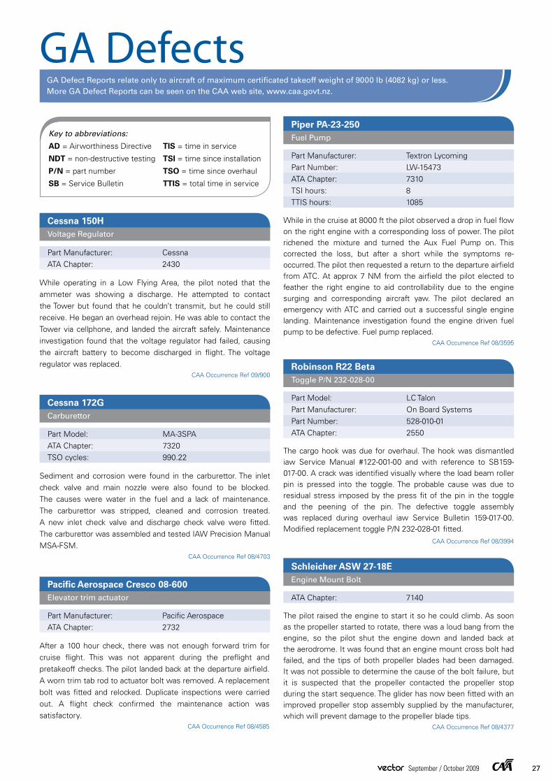
GA DefectsGA Defect Reports relate only to aircraft of maximum certificated takeoff weight of 9000 lb (4082 kg) or less. More GA Defect Reports can be seen on the CAA web site, www.caa.govt.nz.
Key to abbreviations:
AD = Airworthiness Directive TIS = time in service
NDT = non-destructive testing TSI = time since installation
P/N = part number TSO = time since overhaul
SB = Service Bulletin TTIS = total time in service
Schleicher ASW 27-18EEngine Mount Bolt
ATA Chapter: 7140
The pilot raised the engine to start it so he could climb. As soon as the propeller started to rotate, there was a loud bang from the engine, so the pilot shut the engine down and landed back at the aerodrome. It was found that an engine mount cross bolt had failed, and the tips of both propeller blades had been damaged. It was not possible to determine the cause of the bolt failure, but it is suspected that the propeller contacted the propeller stop during the start sequence. The glider has now been fitted with an improved propeller stop assembly supplied by the manufacturer, which will prevent damage to the propeller blade tips.
CAA Occurrence Ref 08/4377
Cessna 150HVoltage Regulator
Part Manufacturer: CessnaATA Chapter: 2430
While operating in a Low Flying Area, the pilot noted that the ammeter was showing a discharge. He attempted to contact the Tower but found that he couldn’t transmit, but he could still receive. He began an overhead rejoin. He was able to contact the Tower via cellphone, and landed the aircraft safely. Maintenance investigation found that the voltage regulator had failed, causing the aircraft battery to become discharged in flight. The voltage regulator was replaced.
CAA Occurrence Ref 09/900
Cessna 172GCarburettor
Part Model: MA-3SPAATA Chapter: 7320TSO cycles: 990.22
Sediment and corrosion were found in the carburettor. The inlet check valve and main nozzle were also found to be blocked. The causes were water in the fuel and a lack of maintenance. The carburettor was stripped, cleaned and corrosion treated. A new inlet check valve and discharge check valve were fitted. The carburettor was assembled and tested IAW Precision Manual MSA-FSM.
CAA Occurrence Ref 08/4703
Pacific Aerospace Cresco 08-600Elevator trim actuator
Part Manufacturer: Pacific AerospaceATA Chapter: 2732
After a 100 hour check, there was not enough forward trim for cruise flight. This was not apparent during the preflight and pretakeoff checks. The pilot landed back at the departure airfield. A worn trim tab rod to actuator bolt was removed. A replacement bolt was fitted and relocked. Duplicate inspections were carried out. A flight check confirmed the maintenance action was satisfactory.
CAA Occurrence Ref 08/4585
Piper PA-23-250 Fuel Pump
Part Manufacturer: Textron LycomingPart Number: LW-15473ATA Chapter: 7310TSI hours: 8TTIS hours: 1085
While in the cruise at 8000 ft the pilot observed a drop in fuel flow on the right engine with a corresponding loss of power. The pilot richened the mixture and turned the Aux Fuel Pump on. This corrected the loss, but after a short while the symptoms re-occurred. The pilot then requested a return to the departure airfield from ATC. At approx 7 NM from the airfield the pilot elected to feather the right engine to aid controllability due to the engine surging and corresponding aircraft yaw. The pilot declared an emergency with ATC and carried out a successful single engine landing. Maintenance investigation found the engine driven fuel pump to be defective. Fuel pump replaced.
CAA Occurrence Ref 08/3595
Robinson R22 BetaToggle P/N 232-028-00
Part Model: LC TalonPart Manufacturer: On Board SystemsPart Number: 528-010-01ATA Chapter: 2550
The cargo hook was due for overhaul. The hook was dismantled iaw Service Manual #122-001-00 and with reference to SB159-017-00. A crack was identified visually where the load beam roller pin is pressed into the toggle. The probable cause was due to residual stress imposed by the press fit of the pin in the toggle and the peening of the pin. The defective toggle assembly was replaced during overhaul iaw Service Bulletin 159-017-00. Modified replacement toggle P/N 232-028-01 fitted.
CAA Occurrence Ref 08/3994
27vector September / October 2009

There were 44 entrants with 1905 photos in all. Some
entered one photo, whereas one entered 619 photos!
We were trying to show a cross-section of the aviation
community in New Zealand, so the finalists were
categorised. There were no entries in the engineering
or airport categories – we’d like to see more next year,
please. There were 80 finalists in the warbird category, 55 in the light aeroplane category, 58 in the classic/vintage category, and 3 in the microlight category, to give you some examples.
We don’t want to reveal the calendar photos yet, so here are some of the other shots of interest.
Photo CompetitionIn January we announced a photo competition that would give us some great aviation shots for the CAA 2010 Calendar, and also be available for us to use in our safety education publications.
The winners are:
Shaddon Waldie
Chris Nielsen
Gavin Conroy
Thierry Huet
Mark Owens
Wendy Peel
Jeremy Stevens
Tony Smith
David CameronChris Nielsen
Pat Scotter
Simon Summerfield