challenging features in design and execution of a low...
TRANSCRIPT
1
Challenging features in design and execution of a low overburden underpass - A case history from Malaysia: PLUS North-South Highway
R.R.Osgoui (1), A. Poli (2), M. Pescara (3), Geodata Engineering SpA. Italy,
Email: (1) [email protected], (2) [email protected], (3) [email protected]
Summary In recent years, the interaction problems between underground and surface structures have been increased rapidly, particularly in urban area. This paper deals with the design and the execution of the low overburden underpass by means of the roof pipe arch umbrella (pipe-roof) to (1) guarantee the stability of face (2) to minimize the surface settlement and (3) to avoid any traffic limits. The case is on going construction of the underpass of PLUS North-South highway in Malaysia by new electrified twin railway tunnels between Padang Besar and Ipoh. The roof pipe arch umbrella was realized by means of pipe-jacking technique which was fulfilled by microtunnelling, so the main aspects on design of roof pipe arch and on the execution difficulties are focused. The underpass section of Berapit twin-tunnels with low overburden of 3–5 m inside residual soil material has a length of 70 m to be pre-supported by a series of steel pipe of 780 mm in diameter for each tunnel. From operational point of view, the implementation of the pipe arch technique involves a number of difficulties and risks including poor ground conditions, low overburden and difficult geometry, presence of existing structures, operation quality, and uncertainties in such complex work. The key technologies, the main procedures, and the involved difficulties were in turn detailed. The mechanism and result of the method is examined based on the data of site observations. Keyword: Underpass, Steel roof pipe arch method, Pre-support method, Pipe jacking technique, microtunnelling, settlement, PLUS highway
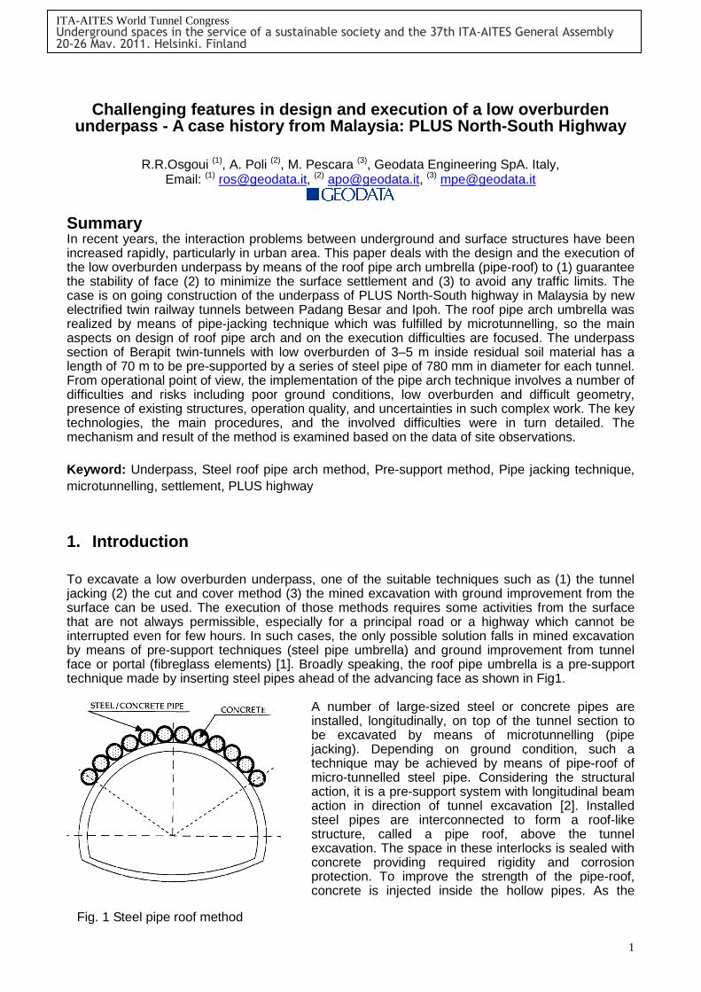
1. Introduction To excavate a low overburden underpass, one of the suitable techniques such as (1) the tunnel jacking (2) the cut and cover method (3) the mined excavation with ground improvement from the surface can be used. The execution of those methods requires some activities from the surface that are not always permissible, especially for a principal road or a highway which cannot be interrupted even for few hours. In such cases, the only possible solution falls in mined excavation by means of pre-support techniques (steel pipe umbrella) and ground improvement from tunnel face or portal (fibreglass elements) [1]. Broadly speaking, the roof pipe umbrella is a pre-support technique made by inserting steel pipes ahead of the advancing face as shown in Fig1.
A number of large-sized steel or concrete pipes are installed, longitudinally, on top of the tunnel section to be excavated by means of microtunnelling (pipe jacking). Depending on ground condition, such a technique may be achieved by means of pipe-roof of micro-tunnelled steel pipe. Considering the structural action, it is a pre-support system with longitudinal beam action in direction of tunnel excavation [2]. Installed steel pipes are interconnected to form a roof-like structure, called a pipe roof, above the tunnel excavation. The space in these interlocks is sealed with concrete providing required rigidity and corrosion protection. To improve the strength of the pipe-roof, concrete is injected inside the hollow pipes. As the
Fig. 1 Steel pipe roof method
ITA-AITES World Tunnel Congress Underground spaces in the service of a sustainable society and the 37th ITA-AITES General Assembly 20-26 May, 2011, Helsinki, Finland
2
excavation progresses, a mechanism of supporting the overburden load by the longitudinal beam action of the pipe-roof is formed. Furthermore, the ground loss control is by far the most important issue for the excavation of an underpass, where ground deformation is a major concern since if not controlled; it leads to accumulation of ground settlement. To minimize the ground settlement, the ground loss should firstly be curtailed. This could be realized by means of pipe-roof technique fulfilled by microtunnelling with constant face pressure. In addition, such a technique also guaranties the stability of longitudinal span of the advancing face and reduces the ground loads on primary supports in such a soft ground. Microtunnelling allows bigger inertia of steel pipes and its ability in directional excavating permits also long perforation without deviation from the ideal axis; accordingly, even though quite expensive , the application of microtunnelling has been increasing [1]. 1.1 State-of-the-art Since the roof pipe method is categorized into one of so-called umbrella method, the innovation and past experiences of this method is briefly reviewed. The invention and successful application of umbrella method have firstly been in Italy and Japan. While tunnelling through poor ground conditions or if there is shallow ground cover above the tunnel crown, the rock or soil mass needs to be reinforced ahead of the face. The umbrella method is a ground reinforcement technique in which all or part of the support of a tunnel section is placed before beginning excavation. The umbrella method is generally employed under the following conditions [2]: • The existence of a shallow overburden above a tunnel • The need to restrict ground surface settlement • Poor ground conditions The problem of tunnel face stability in conjunction with ground surface settlement in urban shallow tunnels has been studied by many researchers. In soil ground condition, the use of pre-reinforcement of the core which has to be excavated, using longitudinal fibreglass pipes grouted into the ground, allows the excavation of tunnels in very difficult ground conditions where the face stability needs to be controlled [3,4,5]. Such a technique is normally coupled with a pre-cut in advance technique, steel pipe umbrella (pipe-roof), or with a jet grouting arch which allows head and bench or full face excavation. One of the successful applications of pipe roof method was in Italy for the construction of the large underground Venezia railroad station in Milan which was 22.8m wide under only 4m overburden [6]. Tan & Ranjith [7] have investigated the effect of the pipe roof umbrella on the convergence of tunnel cavity, on the face deformation, and on the surface settlement by using 2-D finite difference method (FLAC2D). The results of such analyses revealed that the tunnel roof formed by the steel pipes provide a restraining effect on the tunnel induced displacement and helps to reduce the tunnel deformation and corresponding ground surface settlement. Ground settlement directly above the crown could reduce by 40-50% of the settlement produced without any pipe reinforcement. Morita et al. [8] have reported the application of pipe roof umbrella by slurry shield micro-TBM in five different projects in Japan. For one case, they modelled the steel pipe roofs of top of the large cavern by using finite element method. The resulting surface settlement was compared with that of real job condition, taking into account the soil condition for each pipe, jacking force, jacking speed, and the maximum surface settlement after excavation of each pipe roof. Ahuja and Sterling [9] has studied the microtunnelling-assisted pipe roofing by 3-D finite difference method using FLAC3D. The ground loss due to excavating and installation of each pipe roof are

3
modelled and analyzed. The sequential steps including model setup, pipe-roof installation, and tunnel excavation were taken into account in 3-D modelling. Most recently, Poli et al. [1] have integrated the solution of underpass with the risk management approach including design, continuous monitoring, and construction follow-up. Such a comprehensive approach has been proved to be most effective in a successful underpass solution. This overview shows that the roof pipe umbrella technique allowing safe tunnel excavation in difficult ground condition has turned out to be a key part of a successful tunnelling project. 2. Geological-geomechanical condition The ground in which the underpass of PLUS highway was to be constructed was a mix of soil and rock layers. The granite bedrock was expected in a small distance from the right tube invert, over-layered by alluvial soil deposits and residual soil, as a result of the weathered granite, both having poor geotechnical properties. In the upper part the PLUS highway, an embankment is present. In this area, the water level is generally located near the ground surface, keeping the embankment in dry condition. The geotechnical parameters used in design are given in Tab.1.
3. Plus North-South Highway
underpass tunnels The Brapit twin bore tunnels; each 50-60m2 with the total length of 2900m is being excavated through a Granite medium with different degree of weathering and fracturing. The overburden varies between 110m to 220m. At chainage 236.6km this double bore tunnel should have passed beneath the PLUS highway within residual soil and granite bed-rock. The excavation of underpass tunnels interacted with a hydraulic culvert, magnifying the work problem. The layout of the underpass tunnels and existing structures are well presented in Fig. 2. Encountered wholly within soil, the underpass twin tunnels were assigned by the heavy support section type as demonstrated in Fig. 3.
Ground unit Geotechnical parameters Value
Unit weight (γ) kN/m3 19-21
Cohesion (c) kPa 0-20
Friction angle (Φ) ˚ 30-34
Poisson’s ratio (ν) 0.25
Residual soil
Deformation modulus (E) MPa 20-70
GSI (Geological Strength Index) 5-25
Unit weight (γ) kN/m3 24-26
Uniaxial Compressive strength (σci) MPa
10-25
Triaxial test constant mi 10-15
mb 0.4-1.03
s 4.5e-5-0.0002 Hoek-Brown strength parameters
a 0.53-0.58
Poisson’s ratio (ν) 0.2-0.3
Rock mass strength (σcm) MPa 0.01-0.25
Granite bed rock
Deformation modulus (Em) GPa ≤1.1
In-situ stress k=σh/σv at rest 0.5
Fig. 2 The layout of the underpass tunnels and existing structures
NorthNorth--South Expressway (NSE)South Expressway (NSE)
Existing Railway TrackExisting Railway Track
To IpohTo Taiping
YTLCEMENTPLANT
NorthNorth--South Expressway (NSE)South Expressway (NSE)
Existing Railway TrackExisting Railway Track
To IpohTo Taiping
YTLCEMENTPLANT
Pipe Arch Tunnel Pipe Arch Tunnel Crossing NSECrossing NSE
Pipe Arch Tunnel Pipe Arch Tunnel Crossing NSECrossing NSE
Northbound
Southbound
Northbound railway tunnel
Southbound railway tunnel
Northbound
Southbound
Northbound railway tunnel
Southbound railway tunnel
3. Twin pipe arch tunnel crossing underneath PLUS North-South Highway
KM 232.7
3. Twin pipe arch tunnel crossing underneath PLUS North-South Highway
KM 232.7
1. Triple 3m Ф cell drainage culvert at KM 232.6 of PLUS North-South
Highway to replace existing 3m x3m twin box culvert
1. Triple 3m Ф cell drainage culvert at KM 232.6 of PLUS North-South
Highway to replace existing 3m x3m twin box culvert
2. Existing 3m x 3m twin box drainage
culvert to be demolished & replaced
2. Existing 3m x 3m twin box drainage
culvert to be demolished & replaced
Plan Layout of Twin Pipe Arch Tunnel
Table 1 Geotechnical parameters used in numerical analysis

4
4. Numerical analysis
Since the available analytical solutions for pipe roof method are not capable of providing more detailed information on ground deformation and surface settlement, the use of numerical models becomes inevitable. The main aim of the numerical analysis was to investigate the global stability of the tunnel, to verify the adequacy of the tunnel support, to predict the extent of the plastic zone and tunnel convergence, and finally to predict the surface settlement of the PLUS highway, which was the main concern. To achieve this goal, a 2-D plane strain elasto-plastic finite element numerical model was used by using software PHASE2 [10] as its global view is shown in Fig.4.
4.1 Definition of the model To precisely model the excavation steps of the twin-tunnel and to investigate the changes in stresses, displacement, and plasticization of the ground in each step of excavation, it was appropriate that a multi-staged excavation be carried out; accordingly, a total of 14 steps were taken into account to simulate the excavation phases. Following the steps 1 and 2, associated with the geostatic state of the ground and traffic loading respectively, the steps 3 to 8 and 9 to 14 belong to excavation of first and second tunnels, respectively. The staged models should be capable of simulating the deformation which occurs before installation of the support measure. Hence, to let the tunnel be gradually converged, the method of equivalent modulus is used [11]. A gradual reduction in initial modulus of ground zone inside the tunnel boundary (inclusion material) allows the tunnel to be converged until the support measure is installed. The reduced modulus which corresponds to relaxation of 30% resembles the advancement state in which the face reinforcement through fibreglass element is achieved. In numerical model, in order to simulate the presence of the steel-rib embedded within the shotcrete layer the equivalent beam formulation developed by Carranza-Torres [12] was used. The characteristics of the support measures used in numerical analysis are outlined in Tab.2.
Fig. 3 Heavy support section type used for underpass tunnels
Fig. 4 Global view of the numerical model
5
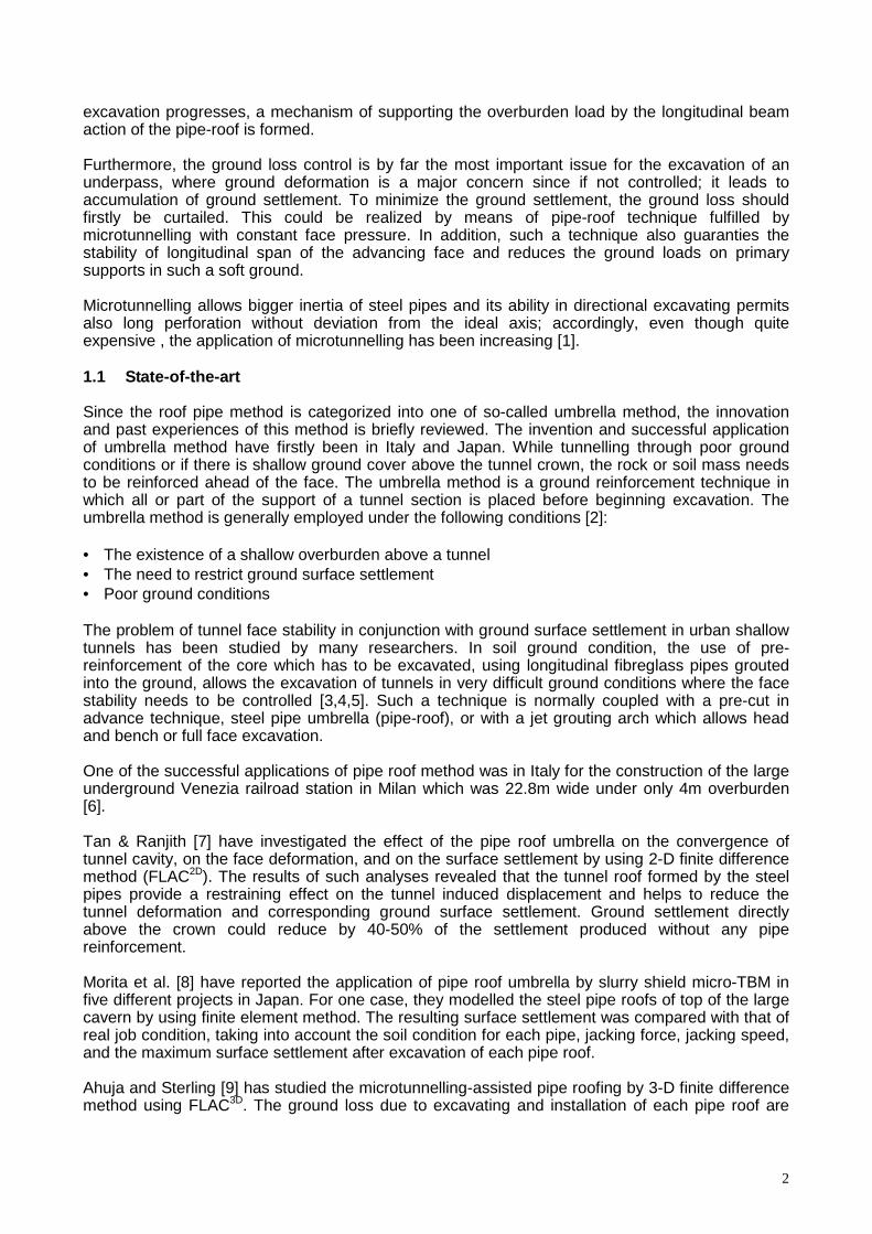
Fig. 5 Displacement and settlement counters after total excavation of both tunnels at the stage 14th
The primary support (shotcrete + steel ribs) was set up after 30% relaxation. This value of 30% relaxation (Pi/P0=0.7) was related to equivalent modulus 19.7 MPa according to Kavvadas formulation [11]. In this case the effects of the gradual excavation, 3-D effect of the face, and the effect of the applied fibre glass elements are quite well-depicted. In order to curtail the ground movement, the in-cast concrete invert was provided at the proximity of the tunnel face. The closing invert prevents the flow of the tunnel upward and controls the displacements of tunnel invert.
4.2 Ground surface settlement As the great concern in construction of underpass was to minimize the surface settlement so the induced settlement should have been traced for all stages. The total induced settlement counters and its transversal profile at the stage 14 are presented in Fig.5 and Fig.6, respectively. The maximum surface settlement was obtained approximately 6.7 mm as the admissible settlement of PLUS highway was defined δadm=20 mm. Using those values it was possible to define the attention and alarm limit related to the surface settlement measurements as indicated in Tab.3. To mitigate the high risk as a consequence of possible failure in construction, a well-organized construction program based on risk management method had to be followed.
Characteristics Roof pipe umbrella
Elasticity modulus (E) 27GPa
Friction angle (Φ) 35°
Cohesion (c) 3.9MPa
Tensile strength (σt) 1.33MPa
Poisson’s ratio (ν) 0.2
Back-fill concrete class Rck=15 MPa
Constitutive law Mohr-Coulomb Elastic
Characteristics Roof pipe umbrella
Equivalent section height (heq) 228mm
Equivalent section area (Aeq) 0.228m2
Equivalent second moment area (Ieq) 0.00099m4
Equivalent Elasticity modulus (Eeq) 10GPa
Poisson’s ratio (ν) 0.2
Constitutive law Timoshenko-Elastic
Table 2 Characteristics of the roof pipe umbrella and support elements used in numerical mode
Fig. 6 Transversal Surface settlement profile due to excavation of underpass twin tunnel
Transversal settlement trough
0
0.001
0.002
0.003
0.004
0.005
0.006
0.007
0.008
-60 -40 -20 0 20 40 60
Distance from pillar center between twin tunnels
Set
tlem
ent
(ver
tica
l dis
pla
cem
ent)
δmax~6.7mm
6
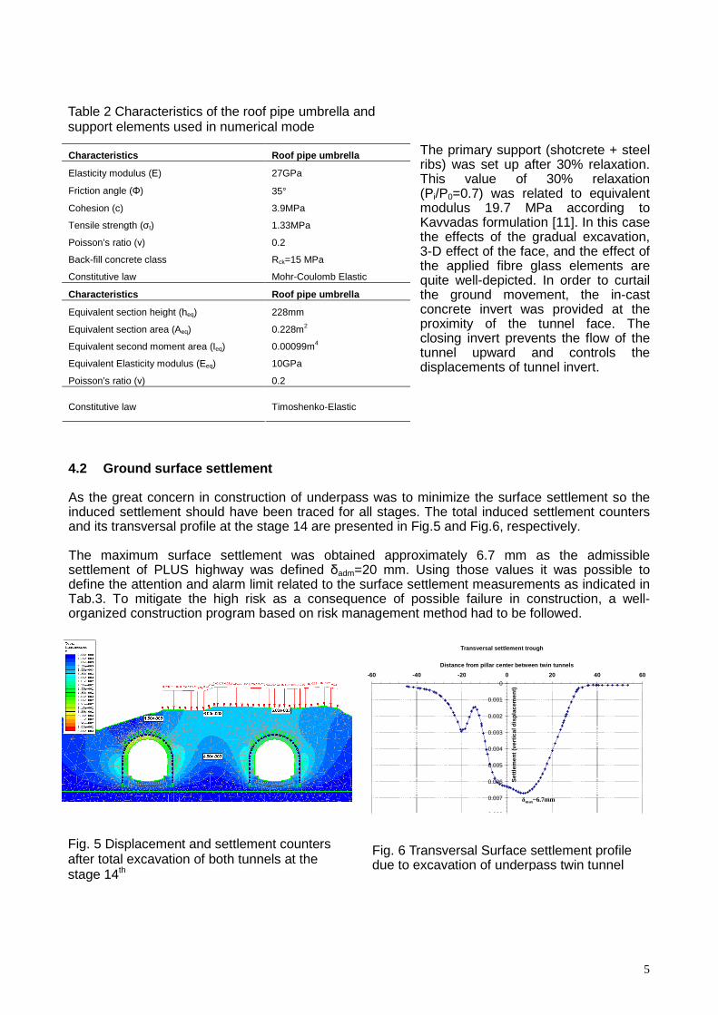
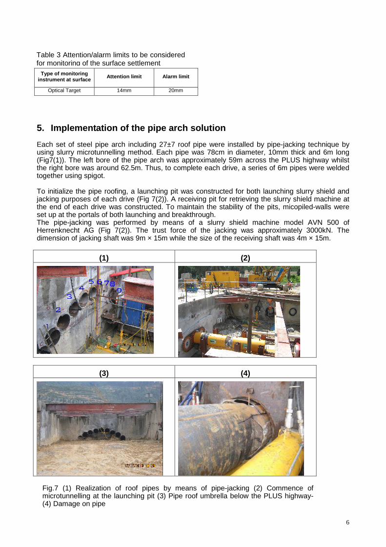
5. Implementation of the pipe arch solution Each set of steel pipe arch including 27±7 roof pipe were installed by pipe-jacking technique by using slurry microtunnelling method. Each pipe was 78cm in diameter, 10mm thick and 6m long (Fig7(1)). The left bore of the pipe arch was approximately 59m across the PLUS highway whilst the right bore was around 62.5m. Thus, to complete each drive, a series of 6m pipes were welded together using spigot. To initialize the pipe roofing, a launching pit was constructed for both launching slurry shield and jacking purposes of each drive (Fig 7(2)). A receiving pit for retrieving the slurry shield machine at the end of each drive was constructed. To maintain the stability of the pits, micopiled-walls were set up at the portals of both launching and breakthrough. The pipe-jacking was performed by means of a slurry shield machine model AVN 500 of Herrenknecht AG (Fig 7(2)). The trust force of the jacking was approximately 3000kN. The dimension of jacking shaft was 9m × 15m while the size of the receiving shaft was 4m × 15m.
(1) (2)
(3) (4)
Type of monitoring instrument at surface Attention limit Alarm limit
Optical Target 14mm 20mm
Fig.7 (1) Realization of roof pipes by means of pipe-jacking (2) Commence of microtunnelling at the launching pit (3) Pipe roof umbrella below the PLUS highway- (4) Damage on pipe
Table 3 Attention/alarm limits to be considered for monitoring of the surface settlement

7
5.1 Challenging issues during execution of the pipe roofing solution 5.1.1 Interaction with hydraulic culvert An existing hydraulic twin-box culvert intersected the right tunnel (Fig.2). In order to allow the pipe jacking execution, it was necessary to demolish partially the existing culvert. To divert the current water of the existing culvert, triple mined tubes, each with diameter of 3.0m, were excavated by means of microtunnelling. Before demolition starts, consolidation of the lateral ground was carried out in order to retain ground after the removal of the culvert and a temporary concrete structure was cast in-placed to support the existing culvert roof and the above highway. Fig 8 shows the work sequences in number order. 5.1.2 Accuracy of pipe steering A major concern when using the roof pipe method is the directional accuracy of pipe placement. The use of pipe-jacking method through microtunnelling makes it possible to minimize the deviation of pipe placement by means of controlling the steering system. The eccentricity of the jacking force or error in steering causes the interruption of the pipe jacking, particularly the breakage of the pipes at welded joints. Such a problem occurred while jacking the pipe N.6 on 27 February 2010 due to pipe breakage (Fig7(4)). The cause of the problem was not immediately known; however, after cleaning of the mud/slurry it was realized that the pipe was broken at the welded joints between 2nd and 3rd pipes as the cutter head and steering component were still beneath the PLUS highway. Firstly it was realized that pull-back of the pipes was not possible and the alternative solutions such as (1) filling the pipe by lean concrete and drilling from the receiving pit by wasting two cutter components; (2) retrieval of cutter components with open cut excavation by sheet-piling were feasible. Nevertheless, the recovery of the pipe and then cutter head together with immediate bentonite backfilling was offered as a practical solution by expert team of TBM driving on account of their experiences. The cause of such a problem was attributed mainly to a mistake in accurate steering of the jacking. 6. Monitoring of the ground settlement During execution of roof pipe umbrella and before commence of tunnel excavation, the surface induced settlement has been continuously measured through several monitoring points located on different positions on PLUS highway surface. To process the monitoring data, the GDMS (Geodata Management System) based on Web-GIS concept and capable of processing on-line the information was used. Such monitoring data has proven to be very effective for management of the
Fig. 8 Work sequences as regards the demolition and improvement of the existing hydraulic culvert

8
construction process to face up with foreseeable sets of anomalous conditions. Fig.9 demonstrates the main window of GDMS system used in this project. The settlement measures determined through different monitoring points indicated that the maximum settlement occurred at the centre of the PLUS highway (Monitoring point M7) exceeded the attention limit (14mm) and approached to 20mm, which was the alarm limit (Fig.10). Such amount of settlement was attributed to the operational work, summarized in (1) lack of special connection clips between contiguous steel pipes, (2) breakage of pipe during pipe jacking and recovery operation, (3) uncertain amount of face pressure of the slurry shield TBM and etc.
7. Conclusions The construction of an underpass by means of conventional excavation method without intervention from the surface necessitates the integration of the design approach and the implementation for such a risky work. Due to ordinary complexity of underpass design and implementation, a risk management program is to a large extent unavoidable. This fact has been examined for the construction of underpass of the PLUS highway in the proximity of the Padang Rengas portal of Berapit tunnel, which involved:
• Avoidance any traffic disturbance at PLUS highway; • Execution of the roof pipe arch solution by means of pipe-jacking technique;
Fig. 9 Monitoring points to measure the ground settlement at the PLUS highway by GDMS
Fig. 10 Maximum vertical displacement measured at monitoring point M7
9
• Existing a hydraulic twin-box culvert to be partially demolished and improved; • Design of a temporary structure at the culvert intersection; • Uncertainties of the bed rock position.
In contrast to design phase, the surface settlement at PLUS highway exceeded the design value due to weaknesses in operational on-site work. In order to reduce the potential risks associated with such a complicated work, the effective risk management approach should be used and it follows the following items:
• The design must take into account the available data and consider all the possible scenarios;
• Monitoring and understanding of ground behaviour: in this very critic context, reaction time to unexpected situations is fundamental. Monitoring must not only be frequent (possibly real-time as usually happen in mechanized excavation) but also continuously analyzed and “under-stood” by experienced technicians who can promptly order to apply counter-measures;
• Counter-measures: in the design stage counter-measures must be well-identified and de-signed but it is compulsory that during the construction stage an experienced site follow-up team is employed to transform the general design recommendations into effective detailed solutions.
The underpass of the PLUS highway demonstrated that the risk management approach (as a sum of design, monitoring and construction follow-up by experienced people) is valid and can be applied to other projects of this kind in the future. The main advantage of this approach is the possibility to introduce its flexibility in a very complex system that intrinsically possesses very low overburden, presence of major highway above the under-pass, existing structures. They are all stiff constraints that reduce the safety margin in terms of not only design level but also of the real possibility of dangerous events. 8. Acknowledgement The authors are grateful to Riccardo Perlo and Davide Agnella for provision of on-site updated data. 9. References
[1] POLI.A, PERRONE. L, and XU. S. “Design and Construction of Low Overburden Underpasses in Urban Areas - Some Examples”, ITA WTC Safe Tunnelling for the City and Environment, Budapest (Hungary), 2009. 23-28.
[2] MURAKI, Y. “The Umbrella Method in Tunnelling”. Ph.D. Dissertation, Massachusetts Institute of Technolgy. 1997.
[3] CARRIERI, G., DE DONATI, A.,GRASSO, P.,MAHTAB, A., AND PELIZZA,S. “Ground Improvement for Rapid Advance of Lonato Road Tunnel Near Verona, Italy. Proc.8th Canadian Tunnelling Conference, “Tunnelling in the 90’s”, Vancover. 1990. pp.243-254.
[4] PELIZZA,S. & PEILA, D. “Soil and Rock Reinforcement in Tunnelling”. Proc 1st Int.Symp.Tunnel Construction and Underground Structures” Ljubliana (Slovenia), 1992., pp.10-31.
[5] PEILA, D. “A Theoretical Study of Reinforcement Influence on the Stability of a Tunnel Face”. Geotechnical and Geological Engineering. 1994. (12):145-168.
[6] LUNARDI, P. “The cellular arch method: Technical solution for the construction of the Milan Railway’s Venezia Station”. Tunnelling and Underground Space Technology. 1990. (5):351-356.
[7] TAN, W.L. & RANJITH, P.G. “Numerical Analysis of Pipe Roof Reinforcement in Soft Ground Tunnelling”.16th ASCE Engineering Mechanics Conference, .University of

10
Washington, Seattle. 2003. [8] MORITA, T., MATSUMOTO, F., SAKAI, E., SHIMADA, H. AND MATSUI, K., “Development
of Support System Using Pipe-jacking for the Roof of the Large Caverns”, 24th Int. Conference and Exhibition - NO-DIG2006, Brisbane. 2006.
[9] AHUJA, V. STERLING, R. L. „Numerical modelling approach for microtunnelling assisted pipe-roof support system”. ITA WTC2008 "Underground Facilities for better Environment and Safety"India, 2008. pp.1678-1687.
[10] Rocscience. A 2-D finite element program for calculating stresses and estimating support around the underground excavations. Geomechanics Software and Research, Rocscience Inc., www.rocscience.com Toronto, Ontario, Canada. 2005.
[11] KAVVADAS, M. “Computational Methods in the Design of Tunnels”. Department of civil engineering. National Technical University of Athens. 2004. 255 pp. (In Greek).
[12] CARRANZA-TORRES, C. “Modelling composite section with Flac or Phase2”. Internal report. Geodata SpA. Turin.2004.