challenges to quality control in bored cast-in-situ piling ... · challenges in urban environment...
TRANSCRIPT
ARTICLE OF PROFESSIONAL INTEREST
Challenges to Quality Control in Bored Cast-In-Situ Pilingin Growing Urban Environment
D. V. Karandikar1
Received: 28 April 2017 / Accepted: 22 September 2017
� Indian Geotechnical Society 2017
Abstract Extensive bored cast-in-situ piling work is being
carried out in growing metropolitan and other large cities
for foundations of multi-storeyed office and residential
buildings, flyovers and for retaining deep excavations for
basements. The roads are small, traffic is heavy, there are
restrictions on timings for movement of construction
machinery and with all these limitations, the owners/clients
require speedy construction of piled foundations to come
‘above ground’ for superstructure construction. Geotech-
nical consultants and piling contractors face tremendous
challenges in urban environment in ensuring quality in
piling work. The challenges relate to all aspects of piling
work such as pile-bore retention during boring, pile tip
zone cleaning, deciding socket lengths in deep weathered
rocks, meeting the pile termination criteria, concreting
without interruptions etc. In case of shoring piles for
basement excavations, installation of anchors adds to a
further challenge since they would penetrate in adjoining
plot. Micropiles are also being extensively used without
regard to their inherent limitations in installation and load
carrying capacity. These aspects are discussed in the pre-
sented paper.
Keywords Bored piles � Quality control �Urban environment � Rotary auger rigs
Introduction
Rapid urbanization of cities with increasing population has
necessitated construction of high rise residential and office
buildings. The building foot-prints are small which result in
imposing high loads columns which in turn are required to
be supported on pile foundations. Bored cast-in-situ piling
becomes the most suitable piling system. In urban envi-
ronment the roads are small, traffic is heavy, there are
restrictions on timings for movement of construction
machinery and with all these limitations, speedy progress is
required. Geotechnical consultants and piling contractors
face tremendous challenges in ensuring quality in piling
work. The challenges relate to all aspects of piling work
such as equipment selection for pile boring, pilebore
retention, pile tip zone cleaning, forming of stipulated
socket length meeting the pile termination criteria and
concreting without interruptions. Challenges also exist
when piles are used for shoring to protect the excavations
for deep basements. Use of micropiles for supporting
building loads or for excavation shoring bring in further
challenges. All these issues are discussed in this paper
based on author’s experience.
Pile Boring Methods
Pile boring is normally carried out by one of the three
methods, viz.,
(a) Chisel–Bailor method using temporary casing
(b) Direct Mud Circulation (DMC) method using ben-
tonite slurry and
(c) deploying Rotary Hydraulic Auger Drilling Rigs.
& D. V. Karandikar
[email protected]; [email protected]
1 D.V. Karandikar & Associates Consulting Engineers,
Vile Parle (East), Mumbai 400057, India
123
Indian Geotech J
DOI 10.1007/s40098-017-0277-z
In congested urban environment all these methods
encounter problems which affect pile installation and its
quality.
Chisel–Bailor Method
In small and narrow access urban plots, this method can be
used. It is slow and uses temporary mild steel (M.S.) casing
for pile bore stability during boring. It is this aspect of use
of a temporary casing that throws in a major challenge. The
depth of a temporary casing is limited to about 6–7 m only.
This is due to the difficulties in casing extraction owing to
large frictional resistance on its outer surface caused by
surrounding soil. Permanent M.S. casing going deeper is
avoided due to its high cost. Thus with short casing, the
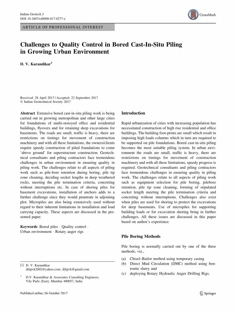
pile bore at lower depth remains vulnerable to caving
resulting in necking, bulging and even loss of concrete in
pile shaft (Figs. 1, 2). Consequently piles have to be either
discarded or derated. Their long term durability also
remains suspect due to reduction in concrete cover. Prob-
lem increases in high sulphate bearing and high chloride
soils which are aggressive to concrete and reinforcement.
DMC Method
This method is faster than Chisel–Bailor but requires
making of bentonite slurry tanks and arranging inflow/
Fig. 1 Necking and bulging
defects in bored cast-in-situ
piles
Fig. 2 Piles with severe shaft integrity problem with loss of concrete
in pile shafts
Indian Geotech J
123
outflow slurry pipes and channels. In urban area, space
restriction often does not permit such an arrangement.
Besides, the site gets very slushy and muck disposal is
delayed due to difficulties in its handling. The environ-
mental norm does not allow slurry disposal in municipal
drains. DMC method therefore is the least preferred one in
urban areas.
Use of bio-degradable polymerfluid is anoption to bentonite
slurry but at present it is not popular with piling contractors due
to higher cost and lack of adequate training in its use.
Hydraulic Rotary Auger Rigs
Due to their fast operation, giving rapid progress in piling
work, use of hydraulic rotary auger rigs is preferred and its
adoption is becoming more and more common. But there
are many issues of quality control, which get overlooked
affecting piling quality. In this paper, these issues have
been more specifically elaborated.
Quality Control Issues with Rotary Auger Piling
These issues relate to (a) selection of rotary rig, (b) local
geological factors, (c) pile bore stability, (d) pile shaft
integrity, (e) pile tip zone cleaning, and (f) concreting
without interruptions. These are discussed below and case
studies are presented to highlight the same.
Selection of Rotary Rig
This should normally be done based on the type of rock, its
strength, extent of fracturing and grade of weathering. The
required rock socket length also, has to be kept in mind.
Site access will also dictate the selection of rig.
Due to extensive piling work that is presently going on,
rotary rigs are in high demand and the piling contractor
tends to use the available rig, either his own or a hired one,
overlooking the need for selection of an appropriate rig for
the rock type and its insitu rock mass condition.
If the rock is hard, lower capacity rigs are not efficient
and the pile termination criterion is not met with and the
socket length gets compromised/reduced. In highly frac-
tured rock, the rock auger teeth/bullets can not properly
grip the joints to rip the rock and pile boring becomes
difficult and time consuming. Teeth/bullets often break,
wear out fast, their replacements do not come in time and
piling gets delayed. Similar is the case when site is filled
with boulders. The boulders tend to fall in pile bore and
boring tends to deviate from verticality.
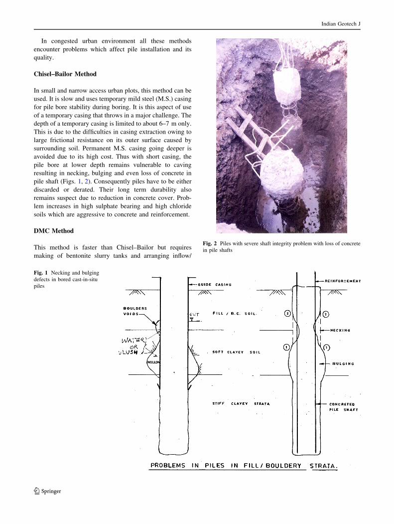
Piling contractors need to seek guidance from the rig
manufacturers on selection of piling rig, cutting tools
etc. Typical guidance from one such manufacturer is
given below in Fig. 3 wherein based on compressive
strength of rock, the type of auger to be used has been
recommended.
Fig. 3 Selection of tools based on rock strength
Indian Geotech J
123
Fig. 4 Present day Mumbai
Indian Geotech J
123
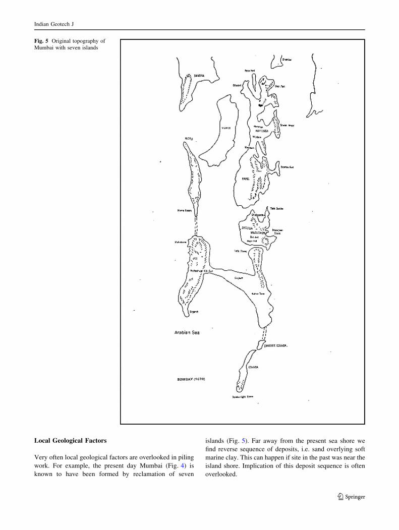
Local Geological Factors
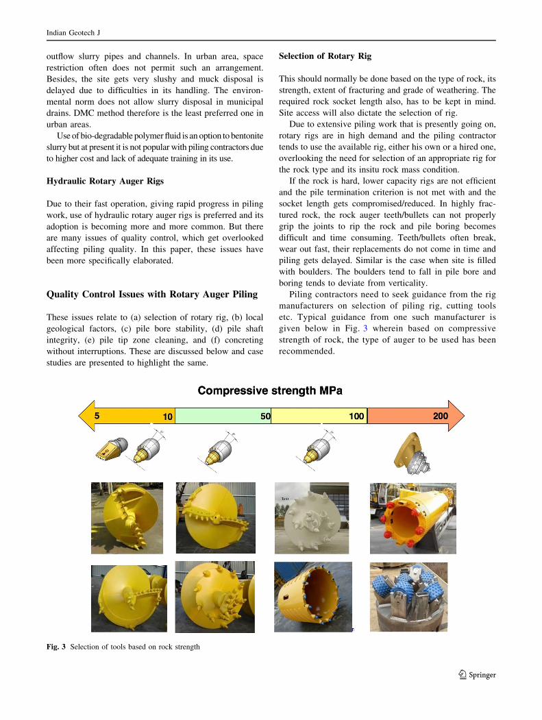
Very often local geological factors are overlooked in piling
work. For example, the present day Mumbai (Fig. 4) is
known to have been formed by reclamation of seven
islands (Fig. 5). Far away from the present sea shore we
find reverse sequence of deposits, i.e. sand overlying soft
marine clay. This can happen if site in the past was near the
island shore. Implication of this deposit sequence is often
overlooked.
Fig. 5 Original topography of
Mumbai with seven islands
Indian Geotech J
123
Fast rotary augering relies on temporary cohesion in
upper sandy strata and formation of slurry due to lower
marine clay for stabilizing the pile bore. This makes the
pile bore prone for slumping. As given in the case studies
presented, the piles at such sites had severe shaft integrity
problem which got further enhanced due to ‘soft toe’
condition. Many piles had to be discarded or drastically
derated and due to smaller foundation footprint, positioning
of new piles became extremely difficult. New piles had to
have permanent M.S. liners and pile tip zone cleaning was
done by airlift method using polymer fluid.
The Mumbai geology also adds to surprises due to
presence of volcanic ash, weak Tuff, Breccia, Intertrappean
Shale in Basalt or Trachyte rock mass. Selection of pile
boring rig needs careful study of borehole and other
geotechnical investigation data. Hydrothermal ‘spheroidal’
weathering of these rocks yields hard boulders in the
matrix of silty clay which fall into pile bore and create
difficulties for maintaining verticality of pile bore. Pres-
ence of Basaltic dykes altogether removes the need for
piling even in a small plot, where some columns would still
need piles.
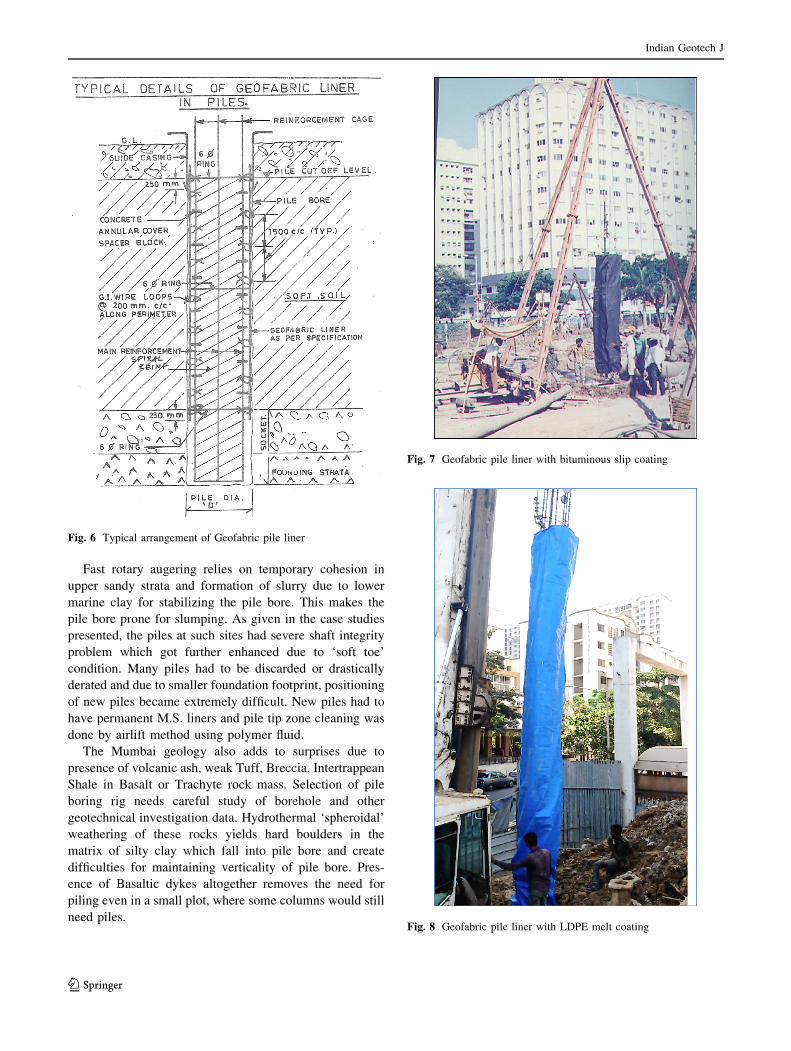
Fig. 6 Typical arrangement of Geofabric pile liner
Fig. 7 Geofabric pile liner with bituminous slip coating
Fig. 8 Geofabric pile liner with LDPE melt coating
Indian Geotech J
123
Pile Bore Stability with Polymer Drilling Fluid
This problem occurs even in rotary piling method, like in
Chisel–Bailor method, when a relatively short temporary
casing is used. Due to difficulties in casing extraction
arising out of limitations of machine capacity, kelly,
hoisting length and absence of oscillatory mechanism, the
casing depth is limited to 6–8 m, leaving the lower pile
shaft vulnerable to necking and pile shaft defects. Ben-
tonite slurry for pile bore stability is avoided due to space
constraints and environmental restriction. Use of polymer
fluid is a good option but not many piling contractors use it.
Polymer fluid is biodegradable, thus environmental
friendly, quantity required is much less than bentonite
which partly offsets its high cost and it is more efficient in
trapping the bored fine muck and its removal. The slurry
can be directly discharged in nearby municipal drains
which removes a major hassel in disposing the site slush.
Pile Shaft Integrity with Geofabric Liner
Permanent pile liners, going up to the start of rock socket,
made from woven or non-woven polypropylene can be
very effectively used to ensure pile shaft integrity, partic-
ularly in bouldery fill or in very soft clays. The liners are
wound around the reinforcement cages and the cages are
lowered in the pile bores stabilized either by bentonite
slurry or by temporary M.S. liners. The alternative of using
permanent M.S. liners in such situations becomes costly.
Apart from economy, geofabric liners increase the pile
concrete durability in aggressive environment. The liners
however have to be properly designed to withstand fluid
concrete pressure and have toughness to prevent their
puncturing in bouldery zone. Figures 6, 7 and 8 show
typical arrangement for use of fabric liner. With LDPE
melt coat on the outer surface of these liners, negative skin
friction can be virtually eliminated in soft clays. Geofabric
liners have been successfully used in bored piles installed
in soft clays in Uran, Nhava Sheva, Navi Mumbai and in
bouldery strata of Eksar, Borivali.
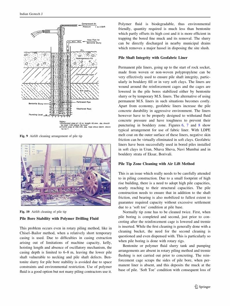
Pile Tip Zone Cleaning with Air Lift Method
This is an issue which really needs to be carefully attended
to in piling construction. Due to a small footprint of high
rise building, there is a need to adopt high pile capacities,
nearly reaching to their structural capacities. The pile
construction needs to ensure that in addition to the shaft
friction, end bearing is also mobilized to fullest extent to
guarantee required capacity without excessive settlement
due to a ‘soft toe’ condition at pile base.
Normally tip zone has to be cleaned twice. First, when
pile boring is completed and second, just prior to con-
creting after the reinforcement cage is lowered and tremie
is inserted. While the first cleaning is generally done with a
cleaning bucket, the need for the second cleaning is
questioned and even dispensed with. This is particularly so
when pile boring is done with rotary rigs.
Bentonite or polymer fluid slurry tank and pumping
arrangements are absent in rotary piling method and tremie
flushing is not carried out prior to concreting. The rein-
forcement cage scraps the sides of pile bore, when per-
manent liner is absent, and this deposits the muck at the
base of pile. ‘Soft Toe’ condition with consequent loss of
Fig. 9 Airlift cleaning arrangement of pile tip
Fig. 10 Airlift cleaning of pile tip
Indian Geotech J
123
pile capacity results even when the founding strata is hard
Basalt rock.
Compressed airlift flushing method suggested by Datye
[1] as illustrated in Fig. 9 is very convenient and should be
encouraged. Its use at one of the sites can be seen in
Fig. 10.
Pile Termination Criteria
This is an issue in deep weathered rocks with variable
weathering grades. The boreholes show low core recovery
and poor RQD. Deciding pile termination criterion is a
challenge. The guidelines given below would be useful in
ensuring piling quality and optimization in their lengths
using one of the two criteria detailed below, viz., Chisel
Energy Level and Pile Penetration Ratio. (Both these
methods have been incorporated as a quality control tool
for Piling in rocks in IRC: 78-2014 [2]).
Chiseling Energy Concept
In rocks, wherein the socket is formed by chiseling, Datye
and Karandikar [3] proposed a simple method based on
Chiseling Energy Concept for the pile termination. The
Project Site: Prabhadevi, Mumbai=aeras/celiP=Amm006=.aiDeliP 0.2827 m2
Pile Installation Chisel Bailor Method
W=Chisel Wt= 16.5 kN
h =Chisel Fall= 0.9 mn = No. of Blowsof Chisel = 450 1/2 hour
Loose Sand 8 0.8
5m d = Pile penetration in cm stipulated time duration,
in stipulated time duration, say half an hourEnergy level E = ( W)* h* n * αα / ( A* d)
Typical Example5.61=Wm01 kN
24
=n6 450 half an houraiDeliP8 = 600 mm
12 A = 0.2827 m2
15m 51 α = 0.8fall = 0.9 md = 5 cm
E = 3782
20m
25
kN/m2/cmFresh
Breccia
Weathered Volcanic Breccia
Murrum Fill 10
3
22 to 33
C.R. 38 to 52% RQD Nil
CR 65 to 97%
Energy Reduction Factor, α =
GWT at 3m
Stiff Silty Clay
Soft Clay
RQD 39 to 97%, UCS:
8MPa
DEPTH, m Cumulative
Hours of Chiselling
Typical Borelog Data
STRATA SPT /CR% RQD%
0
5
10
15
20
25
0 1000 2000 3000 4000 5000
Dep
th (
m )
E=Chiselling Energy Level ( kNm/m2/cm )
Fig. 11 Chisel penetration data, Prabhadevi, Mumbai site
Table 1 Suggested pile design parameters based on chisel energy level of founding basalt rock
Sr.
no.
Rock type C.R.
(%)
R.Q.D.
(%)
Minimum, E (kN m/m2/
cm)
Socket
length
Safe friction qf (kN/
m2)
Safe bearing qb (kN/
m2)
1 Tuff, no plastic fines [ 40 0–25 750 3 pile dia. 100–125 3000
2 Tuff with plastic
fines
[ 40 0–25 750 5 pile dia. 100–125 1800
3 Weathered basalt [ 90 [ 25 2250 0.5 pile dia. 100–150 4000–5000
4 Weathered basalt \ 90 \ 25 2250 3 pile dia. 100–150 4000–5000
Indian Geotech J
123
response of founding rock strata is expressed in terms of
Energy Level, E, (Eq. 1) worked out as under.
E ¼ ðW � h � n � NÞðA � dÞ ð1Þ
E = Chisel energy level in kN m/m2/cm, W = weight of
Chisel in kN in Chisel–Bailor method or the weight of
Direct Mud Circulation (DMC) chisel along with the DMC
rods, in DMC method, h = fall of chisel in meters given in
every blow (m), n = reduction factor, 0.8–1.0 based on
likely drag on chisel due to slurry, submerged weight of
chisel in high ground water, winch rope friction and type of
muck (clayey or sandy), based on rock type. N = no. of
blows in the stipulated duration, normally half an hour.
A = nominal pile cross sectional area in m2, d = pene-
tration in cm into the rock strata in that stipulated duration.
Using analogy of energy imparted in SPT test with
corresponding penetration achieved, pile design parameters
have been suggested by Datye and Patil [4] as given in
Table 1. Capacity estimation based on these parameters is
conservative.
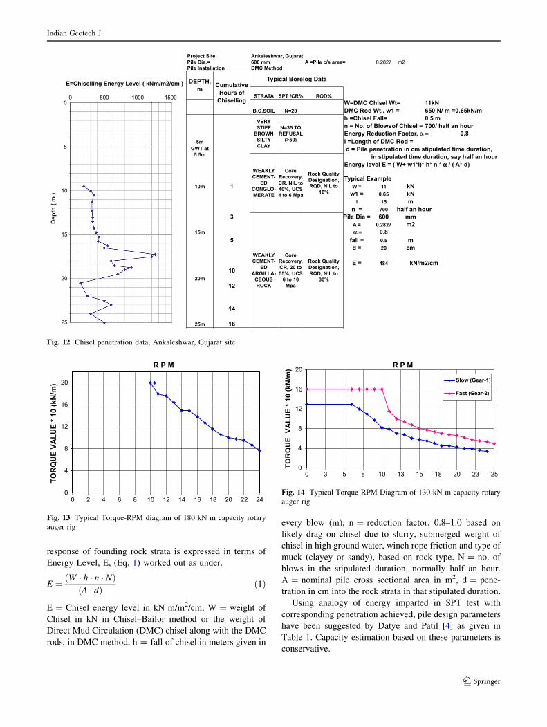
Project Site: Ankaleshwar, GujaratPile Dia.= 600 mm A =Pile c/s area= 0.2827 m2Pile Installation DMC Method
W=DMC Chisel Wt= 11kNDMC Rod Wt., w1 = 650 N/ m =0.65kN/mh =Chisel Fall= 0.5 mn = No. of Blowsof Chisel = 700/ half an hour
0.85m l =Length of DMC Rod =
d = Pile penetration in cm stipulated time duration, in stipulated time duration, say half an hour
Energy level E = ( W+ w1*l)* h* n * αα / ( A* d)
Typical Example10m 1 W = 11 kN
w1 = 0.65 kNl 15 m
n = 700 half an hourmm006=aiDeliP3
A = 0.2827 m215m α = 0.8
=llaf5 0.5 md = 20 cm
E = 48410
20m12
14
25m 16
kN/m2/cmCore
Recovery, CR, 20 to 55%, UCS
6 to 10 Mpa
Rock Quality Designation, RQD, NIL to
30%
Rock Quality Designation, RQD, NIL to
10%
RQD%
B.C.SOIL
VERY STIFF
BROWN SILTY CLAY
WEAKLY CEMENT-
ED CONGLO-MERATE
WEAKLY CEMENT-
ED ARGILLA-
CEOUS ROCK
STRATA SPT /CR%
GWT at 5.5m
Typical Borelog DataCumulative
Hours of Chiselling
DEPTH, m
Energy Reduction Factor, α =N=35 TO
REFUSAL (>50)
Core Recovery, CR, NIL to40%, UCS 4 to 6 Mpa
N=200
5
10
15
20
25
0 500 1000 1500
Dep
th (
m )
E=Chiselling Energy Level ( kNm/m2/cm )
Fig. 12 Chisel penetration data, Ankaleshwar, Gujarat site
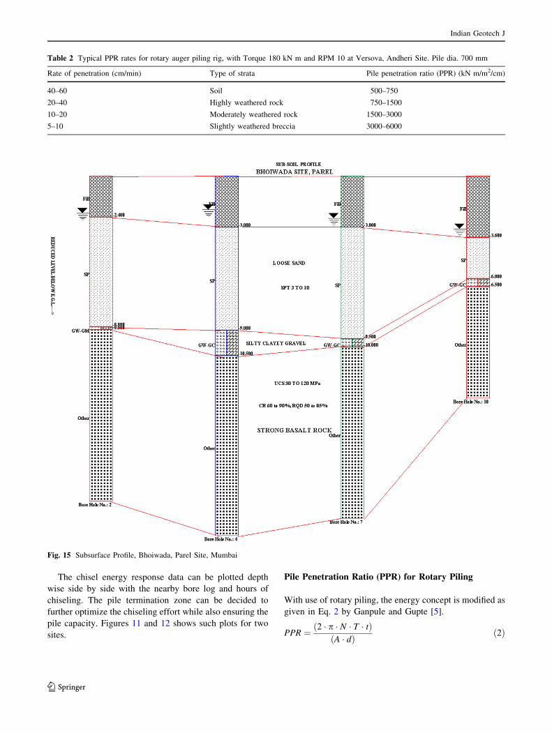
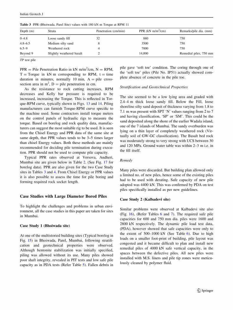
0
4
8
12
16
20
0 2 4 6 8 10 12 14 16 18 20 22 24
TOR
QU
E VA
LUE
* 10
(kN
/m)
R P M
Fig. 13 Typical Torque-RPM diagram of 180 kN m capacity rotary
auger rig
0
4
8
12
16
20
0 3 5 8 10 13 15 18 20 23 25
TOR
QU
E V
ALU
E * 1
0 (k
N/m
) R P M
Slow (Gear-1)
Fast (Gear-2)
Fig. 14 Typical Torque-RPM Diagram of 130 kN m capacity rotary
auger rig
Indian Geotech J
123
The chisel energy response data can be plotted depth
wise side by side with the nearby bore log and hours of
chiseling. The pile termination zone can be decided to
further optimize the chiseling effort while also ensuring the
pile capacity. Figures 11 and 12 shows such plots for two
sites.
Pile Penetration Ratio (PPR) for Rotary Piling
With use of rotary piling, the energy concept is modified as
given in Eq. 2 by Ganpule and Gupte [5].
PPR ¼ ð2 � p � N � T � tÞðA � dÞ ð2Þ
Table 2 Typical PPR rates for rotary auger piling rig, with Torque 180 kN m and RPM 10 at Versova, Andheri Site. Pile dia. 700 mm
Rate of penetration (cm/min) Type of strata Pile penetration ratio (PPR) (kN m/m2/cm)
40–60 Soil 500–750
20–40 Highly weathered rock 750–1500
10–20 Moderately weathered rock 1500–3000
5–10 Slightly weathered breccia 3000–6000
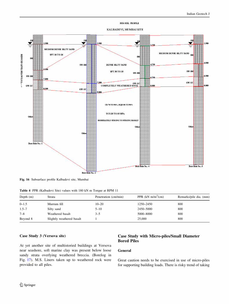
Fig. 15 Subsurface Profile, Bhoiwada, Parel Site, Mumbai
Indian Geotech J
123
PPR = Pile Penetration Ratio in kN m/m2/cm, N = RPM,
T = Torque in kN m corresponding to RPM, t = time
duration in minutes, normally 10 min, A = pile cross-
section area in m2, D = pile penetration in cm.
As the resistance to rock cutting increases, RPM
decreases and Kelly bar pressure is required to be
increased, increasing the Torque. This is reflected in Tor-
que-RPM curve, typically shown in Figs. 13 and 14. Piling
manufacturers can furnish Torque-RPM curve specific to
the machine used. Some contractors install torque meters
on the control panels of hydraulic rigs to measure the
torque. Based on borelog and rock quality data, manufac-
turers can suggest the most suitable rig to be used. It is seen
from the Chisel Energy and PPR data of the same site at
same depth, that PPR values tends to be 3–5 times larger
than chisel Energy values. Both these methods are mainly
recommended for deciding pile termination during execu-
tion. PPR should not be used to compute pile capacity.
Typical PPR rates observed at Versova, Andheri,
Mumbai site are given below in Table 2. (See Fig. 17 for
borelog data). PPR are also given for the two Case Study
sites in Tables 3 and 4. From Chisel Energy or PPR values
it is also possible to assess the time for pile boring and
forming required rock socket length.
Case Studies with Large Diameter Bored Piles
To highlight the challenges and problems in urban envi-
ronment, all the case studies in this paper are taken for sites
in Mumbai.
Case Study 1 (Bhoiwada site)
At one of the multistoried building sites (Typical borelog in
Fig. 15) in Bhoiwada, Parel, Mumbai, following stratifi-
cation and geotechnical properties were observed.
Although bentonite stabilization was initially specified,
piling was allowed without its use. Many piles showed
poor shaft integrity, revealed in PIT tests and low safe pile
capacity as in PDA tests (Refer Table 5). Fallen debris in
pile gave ‘soft toe’ condition. The coring through one of
the ‘soft toe’ piles (Pile No. IP51) actually showed com-
plete absence of concrete in the pile toe.
Stratification and Geotechnical Properties
The site seemed to be a low lying area and graded with
2.4–4 m thick loose sandy fill. Below the Fill, loose
shoreline silty sand deposit of thickness varying from 1.8 to
7.1 m was present with SPT ‘N’ values ranging from 2 to 7
and having classification, ‘SP’ or ‘SM’. This could be the
sand deposited along the shore of the earlier Wadala island,
one of the 7 islands of Mumbai. The sandy overburden was
lying on a thin layer of completely weathered rock (Vir-
tually soil of GW-GC classification). The Basalt bed rock
was moderately strong to very strong with UCS between 30
and 120 MPa. Ground water table was within 2–3 m i.e. in
the fill itself.
Remedy
Many piles were discarded. But building plan allowed only
a limited no. of new piles, hence some of the existing piles
had to be used with derating. Safe capacity of new pile
adopted was 4400 kN. This was confirmed by PDA on test
piles specifically installed as per new guidelines.
Case Study 2 (Kalbadevi site)
Similar problems were observed at Kalbadevi site also
(Fig. 16), (Refer Tables 6 and 7). The required safe pile
capacities for 600 and 750 mm dia. piles were 1600 and
2800 kN respectively. The dynamic pile load test data,
(PDA), however showed that safe capacities were only to
the extent of 500–1000 kN (See Table 6). Due to high
loads on a smaller foot-print of building, pile layout was
congested and it became difficult to plan and install new
remedial piles of 4000 kN safe vertical capacity, in the
spaces between the defective piles. All new piles were
installed with M.S. liners and pile tip zones were meticu-
lously cleaned by polymer fluid.
Table 3 PPR (Bhoiwada, Parel Site) values with 180 kN m Torque at RPM 11
Depth (m) Strata Penetration (cm/min) PPR (kN m/m2/cm) Remarks/pile dia. (mm)
0–4.8 Loose sandy fill 32 880 750
4.8–6.5 Medium silty sand 8 3500 750
6.5–9 Weathered rock 4 7000 750
Beyond 9 Slightly weathered basalt 2 14,000 Remedial piles, 750 mm
TP test pile
Indian Geotech J
123
Case Study 3 (Versova site)
At yet another site of multistoried buildings at Versova
near seashore, soft marine clay was present below loose
sandy strata overlying weathered breccia. (Borelog in
Fig. 17). M.S. Liners taken up to weathered rock were
provided to all piles.
Case Study with Micro-piles/Small DiameterBored Piles
General
Great caution needs to be exercised in use of micro-piles
for supporting building loads. There is risky trend of taking
Fig. 16 Subsurface profile Kalbadevi site, Mumbai
Table 4 PPR (Kalbadevi Site) values with 180 kN m Torque at RPM 11
Depth (m) Strata Penetration (cm/min) PPR (kN m/m2/cm) Remarks/pile dia. (mm)
0–1.5 Murrum fill 10–20 1250–2450 800
1.5–7 Silty sand 5–10 2450–5000 800
7–8 Weathered basalt 3–5 5000–8000 800
Beyond 8 Slightly weathered basalt 1 25,000 800
Indian Geotech J
123

high capacities for micro-piles. But it must be kept in mind
that, (a) lateral capacity of micro-pile is very small.
(b) Micro pile, the way it is constructed commonly in
Mumbai, is actually a small dia bored cast-in-situ pile,
vulnerable to all deficiencies of bored-cast-in-situ piles
mentioned earlier. (c) The load is essentially mobilised due
to shaft friction and FOS of 2.5 is not always ensured.
(d) Pile settlement may exceed failure settlement of (pile
dia/10), under loads less than 2.5 times safe load. (e) There
is PVC or M.S. liner in the overburden but no liner in the
rock socket zone and hence the main pile segment con-
tributing to capacity is vulnerable to corrosion, necking,
‘soft toe’ etc. Following case study will illustrate these
aspects.
Case Study 4 (Vile Parle site)
At a site in Vile Parle, micro-piles were installed for supporting
building extension. Subsurface stratification was as follows:
Layer 1: Backfilled Soil: 1.5 m thick
Layer 2: Grey Stiff Clay: 1.8 m thick, N 8, CH
Layer 3: Yellow Stiff Clay with Gravel: 2.5 m, N 12, CH
Layer 4: Completely Weathered Rock: 0.5–1 m, N 50,
SM-SC
Layer 5: Moderately Weathered Volcanic Breccia:
Beyond 7 m with CR 50%, RQD 30%, UCS 10–20 MPa
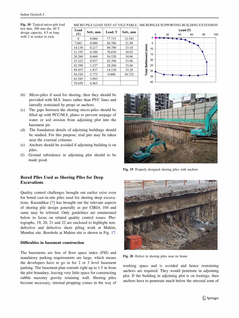
300 mm dia. micro-pile, 8.5 m long with 2 m socket in
rock was designed for a safe capacity of 400 kN. The load
test indicated that settlement for 400 kN was just 1.2 mm
Fig. 17 Borehole data Mahim, Vile Parle and Versova sites, Mumbai
Indian Geotech J
123

but for 800 kN it increased to 15 mm and at 850 kN it
failed with settlement reaching 33 mm. Factor of safety of
2.5 was not met. Typical load settlement curve of micro-
pile test is enclosed (Fig. 18). Allowing very high loads on
micro-piles is definitely risky.
Micro-piles: Guidelines
(a) For design of micro-piles, IRC:SP:109-2015 [6]
should be followed.
Table 5 Mumbai Bhoiwada Site. pile dynamic analyser (PDA) load test data. Piles installed with HR 180 rotary rig with 2 Pile dia. Socket in
rock. All piles 750 mm dia
Bldg. Pile no. PIT comments Qf (kN) Qb (kN) Total capacity (kN) Set (mm) Total settlement (mm) Remarks
1-A 1P 63 No PIT 1240 5 13.3/3 blows Test ok
2-A 1P52 Bulb@4m 520 8 14.3/2 blows Test ok
3-A 1P60 Pile short 990 14 14.1/6 blows Pile cored
4-A 1P53 Pile built up 760 490 1250 8 27.8/5 blows 1st blow
4-A 1P53 1400 1070 2470 7 30.5/5 blows 3rd blow
5-B 2P153 No PIT 1880 10 19.0/7 blows Test ok
6B 2P40 Ok 4560 1 11.1/5 blows Test ok
7-C 3P136 Ok 8070 1 7.2/3 blows Test ok
8-A 1P-20 No PIT 1530 12 26.7/9 blows Test ok
8-A IP-20 2980 10 32.6/9 blows
9 TP1 Bulb@3m 13,000 0.1 8.5/3 blows Ok
10-A 1P52 Bulb@4m – – – Major crushing
11 TP2 Ok – – – –
12 TP3 Ok 7240 3720 10,960 0.1 10.7 Test ok
Table 6 Mumbai Kalbadevi site. Pile dynamic analyzer (PDA) load test data. Piles installed with HR180 rotary rig with 2 pile dia. socket in
rock, all piles 800 mm dia
Pile no. Length (m) Qf (kN) Qb (kN) Qt (kN) Sett. at Qt (mm) qf (kN/m2) qb (kN/m
2) Qt (kN/m2) Qsafe (kN) PIT defect
58 6.23 At 3.4 m
58 5.2 690 910 1600 12.1 103 1800 3183 1000 At 3 m
40 5.74 At 3.3 m
64 6.0 At 3.9 m
121 7.6 At 6 m
121 8.0 1020 290 1310 12 155 578 2606 At 6.9 m
99 5.95 Soft toe
102 6.45 Soft toe
73 5.8 1460 1340 2800 108 222 2660 7060 2250
Table 7 Remedial pile details—Kalbadevi site
Type Qsafe-vert. (kN) Qallow horizontal (kN) Quplift (kN) Allowable settlement (mm) Concrete grade Remarks
I-A 70 M35 Existing, used for only hor. loads
I-B 110 M35
II-A 1250 70 12 M35 Existing
II-B 1600 110 12 M35 Existing
III-A 2500 70 8 M35 Existing
III-B 3100 110 150 8 M35 Existing
IV 4000 110 150 6 M40 New pile
V 4000 110 900 6 M40 New pile
Indian Geotech J
123
(b) Micro-piles if used for shoring, then they should be
provided with M.S. liners rather than PVC lines and
laterally restrained by props or anchors.
(c) The gaps between the shoring micro-piles should be
filled up with PCC/M.S. plates to prevent seepage of
water or soil erosion from adjoining plot into the
basement pit.
(d) The foundation details of adjoining buildings should
be studied. For this purpose, trial pits may be taken
near the external columns.
(e) Anchors should be avoided if adjoining building is on
piles.
(f) Ground subsidence in adjoining plot should to be
made good.
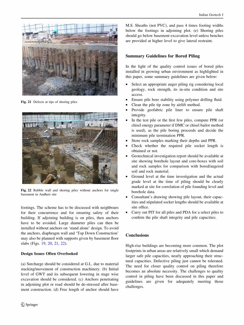
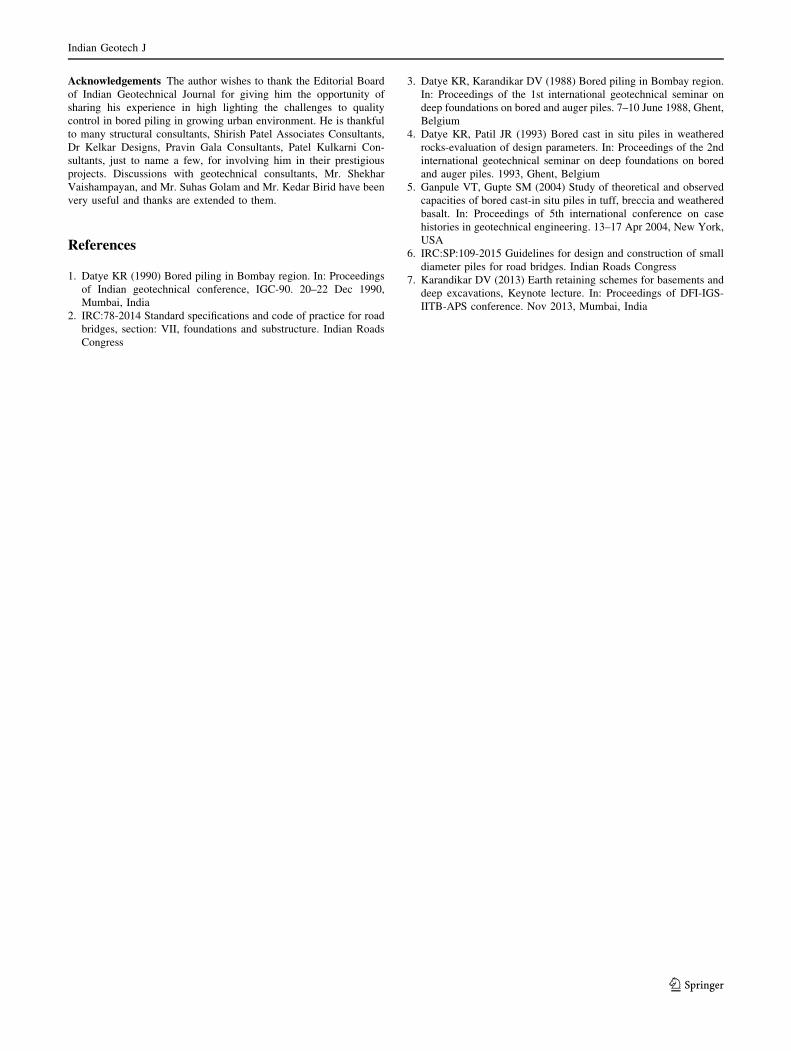
Bored Piles Used as Shoring Piles for DeepExcavations
Quality control challenges brought out earlier exist even
for bored cast-in-situ piles used for shoring deep excava-
tions. Karandikar [7] has brought out the relevant aspects
of shoring pile design generally as per CIRIA 104 and
same may be referred. Only guidelines are enumerated
below to focus on related quality control issues. Pho-
tographs, 19, 20, 21 and 22 are enclosed to highlight non-
defective and defective shore piling work at Mahim,
Mumbai site. Borehole at Mahim site is shown in Fig. 17.
Difficulties in basement construction
The basements are free of floor space index (FSI) and
mandatory parking requirements are large, which means
the developers have to go in for 2 or 3 level basement
parking. The basement plan extends right up to 1.5 m from
the plot boundary, leaving very little space for constructing
rubble masonry gravity retaining wall. Shoring piles
become necessary, internal propping comes in the way of
working space and is avoided and hence restraining
anchors are required. They would penetrate in adjoining
plot. If the building in adjoining plot is on footings, then
anchors have to penetrate much below the stressed zone of
MICRO PILE LOAD TEST AT VILE PARLE , MICROPILES SUPPORTING BUILDING EXTENSION Load (T) Sett., mm Load, T Sett., mm
0 0.000 77.715 12.543 7.065 0.080 84.780 21.98 14.130 0.217 84.780 33.10 21.195 0.380 70.650 34.05 28.260 0.660 56.520 34.06 35.325 0.937 42.390 33.96 42.390 1.237 28.260 33.66 49.455 1.837 14.130 33.28 56.520 3.773 0.000 30.723 63.585 5.093 70.650 6.963
0
5
10
15
20
25
30
35
40
0 20 40 60 80 100
Tot
al S
ettle
men
t (m
m)
Load (T)
Fig. 18 Typical micro-pile load
test data. 300 mm dia, 40 T
design capacity, 8.5 m long
with 2 m socket in rock
Fig. 19 Properly designed shoring piles with anchors
Fig. 20 Defect in shoring piles near tie beam
Indian Geotech J
123
footings. The scheme has to be discussed with neighbours
for their concurrence and for ensuring safety of their
building. If adjoining building is on piles, then anchors
have to be avoided. Large diameter piles can then be
installed without anchors on ‘stand alone’ design. To avoid
the anchors, diaphragm wall and ‘Top Down Construction’
may also be planned with supports given by basement floor
slabs (Figs. 19, 20, 21, 22).
Design Issues Often Overlooked
(a) Surcharge should be considered at G.L. due to material
stacking/movement of construction machinery. (b) Initial
level of GWT and its subsequent lowering in stage wise
excavation should be considered. (c) Anchors penetrating
in adjoining plot or road should be de-stressed after base-
ment construction. (d) Free length of anchor should have
M.S. Sheaths (not PVC), and pass 4 times footing widths
below the footings in adjoining plot. (e) Shoring piles
should go below basement excavation level unless benches
are provided at higher level to give lateral restraint.
Summary Guidelines for Bored Piling
In the light of the quality control issues of bored piles
installed in growing urban environment as highlighted in
this paper, some summary guidelines are given below:
• Select an appropriate auger piling rig considering local
geology, rock strength, its in-situ condition and site
access.
• Ensure pile bore stability using polymer drilling fluid.
• Clean the pile tip zone by airlift method.
• Provide geofabric pile liner to ensure pile shaft
integrity.
• In the test pile or the first few piles, compute PPR (or
chisel energy parameter if DMC or chisel bailor method
is used), as the pile boring proceeds and decide the
minimum pile termination PPR.
• Store rock samples marking their depths and PPR.
• Check whether the required pile socket length is
obtained or not.
• Geotechnical investigation report should be available at
site showing borehole layout and core-boxes with soil
and rock samples for comparison with bored/augered
soil and rock material.
• Ground level at the time investigation and the actual
grade level at the time of piling should be clearly
marked at site for correlation of pile founding level and
borehole data.
• Consultant’s drawing showing pile layout, their capac-
ities and stipulated socket lengths should be available at
site office.
• Carry out PIT for all piles and PDA for a select piles to
confirm the pile shaft integrity and pile capacities.
Conclusions
High-rise buildings are becoming more common. The plot
footprints in urban areas are relatively small which demand
larger safe pile capacities, nearly approaching their struc-
tural capacities. Defective piling just cannot be tolerated.
The need for closer quality control on piling therefore
becomes an absolute necessity. The challenges to quality
control in piling have been discussed in this paper and
guidelines are given for adequately meeting those
challenges.
Fig. 21 Defects at tips of shoring piles
Fig. 22 Rubble wall and shoring piles without anchors for single
basement in Andheri site
Indian Geotech J
123
Acknowledgements The author wishes to thank the Editorial Board
of Indian Geotechnical Journal for giving him the opportunity of
sharing his experience in high lighting the challenges to quality
control in bored piling in growing urban environment. He is thankful
to many structural consultants, Shirish Patel Associates Consultants,
Dr Kelkar Designs, Pravin Gala Consultants, Patel Kulkarni Con-
sultants, just to name a few, for involving him in their prestigious
projects. Discussions with geotechnical consultants, Mr. Shekhar
Vaishampayan, and Mr. Suhas Golam and Mr. Kedar Birid have been
very useful and thanks are extended to them.
References
1. Datye KR (1990) Bored piling in Bombay region. In: Proceedings
of Indian geotechnical conference, IGC-90. 20–22 Dec 1990,
Mumbai, India
2. IRC:78-2014 Standard specifications and code of practice for road
bridges, section: VII, foundations and substructure. Indian Roads
Congress
3. Datye KR, Karandikar DV (1988) Bored piling in Bombay region.
In: Proceedings of the 1st international geotechnical seminar on
deep foundations on bored and auger piles. 7–10 June 1988, Ghent,
Belgium
4. Datye KR, Patil JR (1993) Bored cast in situ piles in weathered
rocks-evaluation of design parameters. In: Proceedings of the 2nd
international geotechnical seminar on deep foundations on bored
and auger piles. 1993, Ghent, Belgium
5. Ganpule VT, Gupte SM (2004) Study of theoretical and observed
capacities of bored cast-in situ piles in tuff, breccia and weathered
basalt. In: Proceedings of 5th international conference on case
histories in geotechnical engineering. 13–17 Apr 2004, New York,
USA
6. IRC:SP:109-2015 Guidelines for design and construction of small
diameter piles for road bridges. Indian Roads Congress
7. Karandikar DV (2013) Earth retaining schemes for basements and
deep excavations, Keynote lecture. In: Proceedings of DFI-IGS-
IITB-APS conference. Nov 2013, Mumbai, India
Indian Geotech J
123