challenges in design, operation and control of subsea...
TRANSCRIPT

1
1
1
Esmaeil Jahanshahi | Challenges in design, operation and control of subsea separation processes
Public Trial Lecture
Challenges in design, operation and control of subsea separation processes
PhD Candidate: Esmaeil Jahanshahi
Trial Lecture – October 18th 2013, NTNU, Trondheim
2
2
Esmaeil Jahanshahi | Challenges in design, operation and control of subsea separation processes
Outline• Introduction• Challenges
– Design challenges– Power system
• Conventional subsea separation– Examples: Troll pilot, Tordis SSBI– Process control– Simulation study in OLGA
• Subsea gas separation systems– Examples: Pazflor (Angola), Åsgard (Norway)
• Compact subsea separation systems– Examples: Perdido (Mexico), Marlim (Brazil)– Process control (Marlim)
• Summary

2
3
3
Esmaeil Jahanshahi | Challenges in design, operation and control of subsea separation processes
Where subsea separation used until now:
• High water-cut and limited water handling capacity on topside
• Low reservoir pressure
Advantages:
• Increased production– Decreasing static head on oil wells
– Added water treatment capacity
• Improved recovery of reservoir
• Decreased produced water emission to environment
• Performing functions at seabed instead of topside (limited space)
Future vision:
• Moving all processes to subsea
Introduction
4
4
Esmaeil Jahanshahi | Challenges in design, operation and control of subsea separation processes
Subsea processing
Gustafson et al. (2000)
At least one of these tasks: • Water separation and injection• Oil and gas boosting (multiphase pump)• Gas separation• Gas compression

3
5
5
Esmaeil Jahanshahi | Challenges in design, operation and control of subsea separation processes
Challenges in subsea separation
6
6
Esmaeil Jahanshahi | Challenges in design, operation and control of subsea separation processes
• Maximum oil/water interface area (long separators)
• Reduction of inlet fluid momentum (laminar flow good separation)
• Oil in injected water less than 1000 ppm
• High pressure (160-180 bars)
• Huge throughput (water: 6000 m3/day, oil: 4000 m3/day)
• Well-stream flow rate variations (slugs)
• Future process modification is not possible
Horn et al. (2003)
Challenges in separator design

4
7
7
Esmaeil Jahanshahi | Challenges in design, operation and control of subsea separation processes
• Low maintenance
• Failure tolerance against sand, clogging, erosion (30 years)
• Reduction of emulsions (Inlet assembly, Chem. demulsifier)
• Sand removal system– Usually disposed with the water into an injection well
• Hydrate strategy (Troll Pilot: 60 C, Insulation)
• Supply of chemicals (Methanol, Scale inhibitor, Demulsifier)
Challenges in separator design
8
8
Esmaeil Jahanshahi | Challenges in design, operation and control of subsea separation processes
• Effective (sensitive) methods– Inductive
– Nucleonic (can identify emulsion layer and oil/gas boundary)
• Redundancy
• No moving parts for durability and low maintenance
• Easily retrievable by a ROV (Remotely Operated Vehicle)
• Long term durability in presence of chemicals
Horn et al. (2003)
Challenges in level detection system designTo identify the boundary between thewater phase and the oil phase.

5
9
9
Esmaeil Jahanshahi | Challenges in design, operation and control of subsea separation processes
Sand may cause
• Degradation of pumps due to wear
• Clogging of separation equipment
• Erosion of pipelines
Where the sands should be routed?!
• Re-injected with the water (Tordis field: 500 kg/d)– Includes bypass of sand around the water injection pump
• Recombined with oil and transported to surface (Pazflor field, Angola)
• Stored / disposed in another way
Vu et al. (2009)
Sand Handling Challenge
10
10
Esmaeil Jahanshahi | Challenges in design, operation and control of subsea separation processes
Subsea Power Distribution
Source: SIEMENS
Subsea power distribution technologiesRelative importance
AC is the key focus area today, while DC by most are put off for the next 3-5 years
• 10-30 MW (Pumps & Compressors)
• 72 kV power lines and connectors
• 50-100 km Step-out

6
11
11
Esmaeil Jahanshahi | Challenges in design, operation and control of subsea separation processes
Reactive Power Loss• Reactive power loss is due to capacitance of cables
• CD current does not induce reactive power (CD transmission)
• It requires AC-to-DC and DC-to-AC convertors
dVI C
dt
1cZ
j C
Impedance:
12
12
Esmaeil Jahanshahi | Challenges in design, operation and control of subsea separation processes
Subsea Power Distribution
Main Components in Power Grid (Siemens Subsea)
Transformer Switchgear Variable speed drives
Source: SIEMENS
• Subsea Step Down Transformer• 3000 m (10.000 feet)• 30 years design life
Drives for Multiphase Boosting Pumps, Compressors and Water Injection Pumps

7
13
13
Esmaeil Jahanshahi | Challenges in design, operation and control of subsea separation processes
Conventional subsea separation
14
14
Esmaeil Jahanshahi | Challenges in design, operation and control of subsea separation processes
Troll Pilot: World’s first subsea separation
Gustafson et al. (2000), Horn et al. (2002), Horn et al. (2003)
Troll Pilot (Norway)ABB, Norsk Hydro (2001)Size: 17×17×8 mWeight: 350 tonsWater depth: 300 mDesign pressure: 150 barsPump: Framo 35-180 bars
Main tasks: water separation and injection

8
15
15
Esmaeil Jahanshahi | Challenges in design, operation and control of subsea separation processes
Tordis SSBI(Subsea Separation Boosting & Injection)
Siversten et al (2006)Tordis Field (Norway)FMC (2007)Weight: 1000 tonsWater depth: 200 mDesign pressure: 345 barsPump: Framo 2.3 MW
FMC Technologies website, Gjerdseth et al. (2007)
Main elements:Foundation Structure and Manifold Separator Module Sand Removal System Water Injection Pump (WIP)Multiphase Pump (MPP)
16
16
Esmaeil Jahanshahi | Challenges in design, operation and control of subsea separation processes
Process Control: Tordis SSBI
Siversten et al. (2006), Faanes et al. (2007)

9
17
17
Esmaeil Jahanshahi | Challenges in design, operation and control of subsea separation processes
Process Control: OLGA Simulations
18
18
Esmaeil Jahanshahi | Challenges in design, operation and control of subsea separation processes
Process Control: OLGA SimulationsSeparator pressure [bar]
MMP pump speed [rpm] WIP pump speed [rpm]
Water level [m]
feed rate [kg/s]
Disturbance in feed rate (well test)
Topside flow rate [kg/s]
10
19
19
Esmaeil Jahanshahi | Challenges in design, operation and control of subsea separation processes
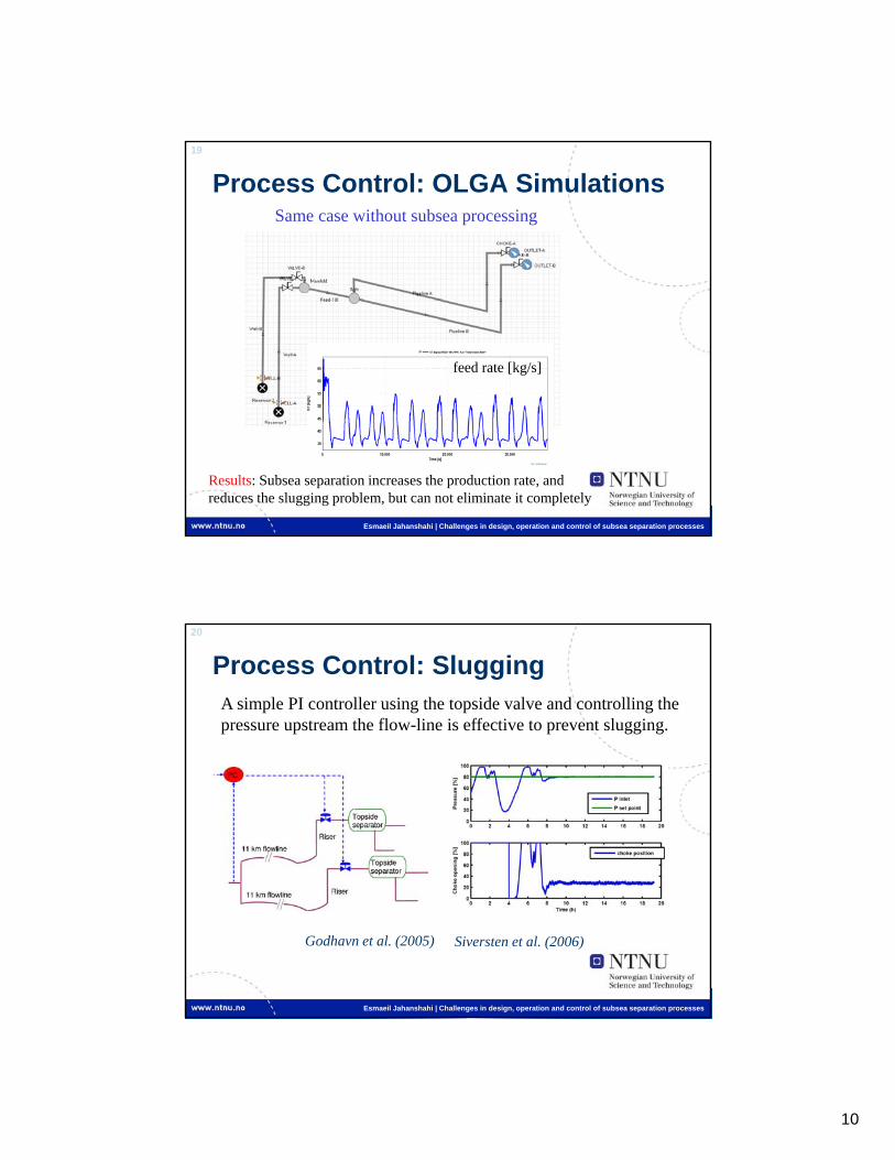
Process Control: OLGA Simulations
feed rate [kg/s]
Same case without subsea processing
Results: Subsea separation increases the production rate, and reduces the slugging problem, but can not eliminate it completely
20
20
Esmaeil Jahanshahi | Challenges in design, operation and control of subsea separation processes
Process Control: Slugging
Godhavn et al. (2005)
A simple PI controller using the topside valve and controlling the pressure upstream the flow-line is effective to prevent slugging.
Siversten et al. (2006)

11
21
21
Esmaeil Jahanshahi | Challenges in design, operation and control of subsea separation processes
Process Control: Cascade control
Siversten et al. (2006)
Amount of water that topside can handle is limited
22
22
Esmaeil Jahanshahi | Challenges in design, operation and control of subsea separation processes
Process Control: Well head pressure
Siversten et al. (2006)
During the well test, the manifold pressure is kept constant

12
23
23
Esmaeil Jahanshahi | Challenges in design, operation and control of subsea separation processes
Subsea gas-liquid separation
24
24
Esmaeil Jahanshahi | Challenges in design, operation and control of subsea separation processes
• Rules of thumb:– Typical multiphase vertical gradient: 0.3 psi/foot
– Typical multiphase pipeline frictional loss: 50 psi/mile
– Maximum boosting by a multiphase pump: 700 psi (50 bars)
Example: A reservoir in 6000’ of water depth located 15 miles from the potential host.
6000*0.3 = 1800 psi
15*50 = 750 psipotential pump duty = 2350 psi (160 bar)
Vu et al. (2009)
Subsea gas/liquid separation is required(Higher hydraulic efficiency of single phase pumps)
Boosting Power

13
25
25
Esmaeil Jahanshahi | Challenges in design, operation and control of subsea separation processes
• Is it done by vertical separators– Height 9 m
– Diameter 3.5 m
Subsea gas-liquid separation
Pazflor field (Angola)Total & FMC (2011)Size: 21×21×19 mWeight: 900 tonsWater depth: 800 mDesign pressure: 345 barsPumps: Hybrid to 18% GVF
- No Slugging- Easier gas-lift
Where is it used: reservoirs with high GOR and gas fields
26
26
Esmaeil Jahanshahi | Challenges in design, operation and control of subsea separation processes
Subsea gas-liquid separation: Pazflor
Bon (2009)

14
27
27
Esmaeil Jahanshahi | Challenges in design, operation and control of subsea separation processes
Subsea gas-liquid separation: Åsgard
Hodne (2012)
Åsgard (Norway)Aker Solutions (2015)Size: 44×74×24 mWeight: 4800 tonsWater depth: 250-325 mTie back: 50 kmPower: 2×11.5 MWFlow rate: 21 mill Sm3/dDiff. pressure: 50 bar
Gas-condensate separationGas compression
28
28
Esmaeil Jahanshahi | Challenges in design, operation and control of subsea separation processes
Subsea gas-liquid separation: Åsgard
Hodne (2012)

15
29
29
Esmaeil Jahanshahi | Challenges in design, operation and control of subsea separation processes
Compact subsea separation systems
30
30
Esmaeil Jahanshahi | Challenges in design, operation and control of subsea separation processes
Compact subsea separators
For heavy oil or deep water applications:
• Inlet separation technology applying high G-force- Continuous Deflective Separation (CDS) Technology
• Separation in pipe segments instead of in large vessels
• Use of electrostatic coalescence technique
Vu et al. (2009)
16
31
31
Esmaeil Jahanshahi | Challenges in design, operation and control of subsea separation processes
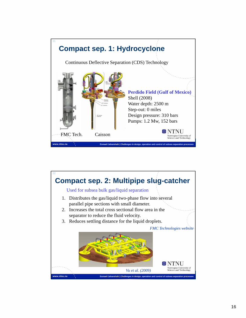
Compact sep. 1: Hydrocyclone
Continuous Deflective Separation (CDS) Technology
Perdido Field (Gulf of Mexico)Shell (2008)Water depth: 2500 mStep-out: 0 milesDesign pressure: 310 barsPumps: 1.2 Mw, 152 bars
FMC Tech. Caisson
32
32
Esmaeil Jahanshahi | Challenges in design, operation and control of subsea separation processes
Compact sep. 2: Multipipe slug-catcher
1. Distributes the gas/liquid two-phase flow into several parallel pipe sections with small diameter.
2. Increases the total cross sectional flow area in the separator to reduce the fluid velocity.
3. Reduces settling distance for the liquid droplets.
Used for subsea bulk gas/liquid separation
FMC Technologies website
Vu et al. (2009)

17
33
33
Esmaeil Jahanshahi | Challenges in design, operation and control of subsea separation processes
Compact sep. 3: Pipe separator
Sagatun et al. (2008)HarpPipe
separator
Outletvessel
Used for subsea bulk water separation
Patented by Norsk Hydro (Statoil)
Utilizes effect of small diameter and short residence time
34
34
Esmaeil Jahanshahi | Challenges in design, operation and control of subsea separation processes
Compact sep. 3: Pipe separator
Marlim Field (Brazil)FMC & Petrobras (2011)Water depth: 870 mSize: 29×10.8×8.4 mWeight: 392 ton
Orlowski et al. (2012)
SSAO: separação submarina água-óleo

18
35
35
Esmaeil Jahanshahi | Challenges in design, operation and control of subsea separation processes
Marlim subsea separation (Brasil)
A – Multiphase desanderB – HarpC – Tubular separatorD – Outlet vesselE – Water desanderF – HydrocycloneG – PumpH – OIW monitorI – Ejector
Orlowski et al. (2012)
I
I
36
36
Esmaeil Jahanshahi | Challenges in design, operation and control of subsea separation processes
Ejector
An Ejector is a simple device which uses the energy within a high pressure fluid to entrain and compress a low pressure fluid to an intermediate pressure.

19
37
37
Esmaeil Jahanshahi | Challenges in design, operation and control of subsea separation processes
10 modules considered for Marlim subsea project (Brasil)
1. By-pass module
2. Multiphase sand remover module (desnader module)
3. Pipe separator module
4. Water sand remover system (desander module)
5. Hydrocyclone module
6. Pump module
7. Water injection choke module
8. Recirculation module
9. Flushing module
10. Electro-hydraulic module for multiplex control (EHCM)
Modularization
Orlowski et al. (2012)
38
38
Esmaeil Jahanshahi | Challenges in design, operation and control of subsea separation processes
Process Control: Marlim SSAO
Pereira et al. (2012)
Challenges:
• Strong interactions between different process components• Stiff system dynamics due to small hold-ups and low GOR• Pressure drops of inlet cyclonic equipment need to be balanced• Constraints on valve opening/closing speed• Instrumentation is limited compared to top-side
Sensors:
• Differential pressure transmitters• Pressure and temperature transmitters• Flow transmitters• Density profiler• Sand detector• Oil in water monitor

20
39
39
Esmaeil Jahanshahi | Challenges in design, operation and control of subsea separation processes
Process Control: Marlim SSAOLevel controller
Pereira et al. (2012)
HarpPipe
separator
OutletVessel
• Quick response is required (3 sec)• To avoid constant speed changes a dead band is used• Filtration of input can be used
40
40
Esmaeil Jahanshahi | Challenges in design, operation and control of subsea separation processes
Process Control: Marlim SSAOTwo pump flow rate controllers (Min/Max flow)
Pereira et al. (2012)
• To keep the operating point inside the pump envelope• Min opens when flow is less than minimum• Max closes when flow is more than maximum

21
41
41
Esmaeil Jahanshahi | Challenges in design, operation and control of subsea separation processes
Process Control: Marlim SSAOMultiphase choke valve-DP controller
Pereira et al. (2012)
• To maintain stable backpressure for the rejects from desnader and hydrocyclone
• Asymmetrical dead band is applied to reduce choke movements
42
42
Esmaeil Jahanshahi | Challenges in design, operation and control of subsea separation processes
Process Control: Marlim SSAOTwo hydrocyclone controllers
Pereira et al. (2012)
• To keep the reject rate between 2-6%

22
43
43
Esmaeil Jahanshahi | Challenges in design, operation and control of subsea separation processes
Process Control: Marlim SSAOFlushing controller
Pereira et al. (2012)
• Is active only when pipe separator flushing sequence is executed• Adjusts pump speed to achieve required flow velocity
44
44
Esmaeil Jahanshahi | Challenges in design, operation and control of subsea separation processes
Operation: Automated sequences
Pereira et al. (2012)
• Start up of water injection pump• Flushing sequence• Planned shutdowns• Injecting chemicals
Screenshot of flushing sequence

23
45
45
Esmaeil Jahanshahi | Challenges in design, operation and control of subsea separation processes
Dynamic Analysis
Pereira et al. (2012)
• Verification of control philosophy• Pre-tuning PID controllers (SIMC)• Verification and development of
automated sequences
Hydrocyclone model in Unisim or HYSYS Simulation of flushing sequence
46
46
Esmaeil Jahanshahi | Challenges in design, operation and control of subsea separation processes
• Sand removal
• Flow assurance e.g. Hydrates (MEG injection, depressurizing)
• Secure foundation & Leveling of subsea separators
• Durability & Low maintenance
• Modularization
• Power distribution
• Compactness for deep-water applications
• Laboratory test (Technology Qualification Program)
SummaryMain challenges in design

24
47
47
Esmaeil Jahanshahi | Challenges in design, operation and control of subsea separation processes
• Simpler (compared to topside control systems )
• Strong interactions between control loops
• Redundancy
• Safety & Emergency Shutdown (ESD)
• Fast dynamics of compact separators
• Data transfer to topside- Comes-on-power (slow, suitable for old bulky systems)
- Fiber optic communication (fast, high rate, long distance)
• Modeling and dynamic simulations
• Controller tuning
• Wear and tear of control valves (constraint on speed of valves)
• Slugging flow and well-test
SummaryMain challenges in process control
Strong interaction + constraint handling + economic operation MPC
48
48
Esmaeil Jahanshahi | Challenges in design, operation and control of subsea separation processes
Thank you!
References1. Bon (2009), Pazflor, A World Technology First in Deep Offshore Development, SPE 123787
2. Faanes et al. (2007), Process Control of a Subsea Production Plant, DYCOPS, Mexico
3. Gjerdseth et al. (2007), The Tordis IOR Project, OTC 18749
4. Godhavn et al. (2005), Increased oil production by advanced control of receiving facilities, IFAC Czech Republic
5. Gustafson et al. (2000), Subsea Separation: The Way Into the New Millennium, OTC 12015
6. Hodne (2012), Subsea processing and transportation of hydrocarbons, Statoil
7. Horn et al. (2002), Troll Pilot - Definition, Implementation and Experience, OTC 14004
8. Horn et al. (2003), Experience in operating World's first Subsea Separation and Water Injection Station at Troll Oil Field in the North Sea, OTC 15172
9. Orlowski et al. (2012), Marlim 3 Phase Subsea Separation System – Challenges and Solutions for the Subsea Separation Station to Cope with Process Requirements, OTC 23552
10. Pereira et al. (2012), SS: Marlim 3 Phase Subsea Separation System: Controls Design Incorporating Dynamic Simulation Work, OTC 23564
11. Siversten et al. (2006), Control Solurions for Subsea Processing and Multiphase Transport, AFCHEM, Brazil
12. Sagatun et al. (2008), The Pipe Separator: Simulations and Experimental Results, OTC 19389
13. Vu et al. (2009), Comparison of Subsea Separation Systems, OTC 20080