challengerim2 - et systems · with plug-in transformer). 13. oil filler port 14. magnetic reed...
TRANSCRIPT

1
ET 500INSTALLERS’ MANUAL
2 0 0 6
(Remove these pages when done and issue the balance of thisbooklet to the end-user)

2
1. WHAT’S IN THE BOX A l i s t of contents you wi l l receive with th is product and technical speci f icat ions
2. WHAT’S NOT IN THE BOX A l i s t of opt ional accessor ies avai lable for th is product. P lease contact your E.T suppl ier for more information.
3. RECOMMENDED TOOLS A l i s t of tools recommended for the instal lat ion of th is product
4. IMPORTANT: BEFORE INSTALL ING What you need to know before instal l ing th is product.
PLEASE ENSURE THAT YOU READ AND UNDERSTAND THIS SECT IONBEFORE INSTALL ING THE PRODUCT.
Th is sect ion h ighl ights any special warn ings and precaut ions.
5. INSTALL ING THE HARDWARE
6. WIRING & SCHEMATICS
7. PROGRAMMING & SELECTING MODE OPTIONS
6
7
10
15
18
5
3
Gate mechanicsCabling requirements
Base plate mountingGearbox mountingMounting the rackMounting and adjusting the limit actuatorsAdjusting motor final position
INDE
X

3
IN THE BAG· 4 x M10 J-bolts· 8 x M10 machine nuts· 8 x M10 flat washers· 4 x M10 nylock nuts· 1 x adjustable base plate· 1 x anti-lift bracket
1. CONTROL CARD2. CONTROL BOX WITH LID3. EIGHT POLE RING MAGNET4. MOTOR5. REPLACEABLE MOTOR BRUSHES6. POWER SUPPLY UNIT AC
PRESENT LED (ACDC ONLY)7. REMOVABLE SIDE VENT TO GAIN
ACCESS TO MOUNTING HOLES8. LOCK FOR MANUAL RELEASE
Figure 3.1W
HA
T’S
IN T
HE
BOX
MOTOR UNIT COIMPLETE(see below for identification of operator components)
· 2 x M8 nylock nuts· 2 x M8 square flat washers· 2 x limit actuators· 2 x self-tapping screws & guides· 1 x bottle gearbox oil (80W/90)· 2 x manual release keys
9. MANUAL RELEASE ASSEMBLY10. GEARBOX11. 12V BATTERY12. PSU POWER SUPPLY UNIT FOR
ET-500 ACDC (ET-500 12V COMESWITH PLUG-IN TRANSFORMER).
13. OIL FILLER PORT14. MAGNETIC REED LIMIT SWITCHES15. PINION GEAR
1
2 3
4
5
6
78
12
15
7
9
10
14
1311
4
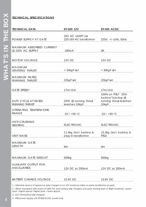
TECHNICAL SPECIFICATIONS
POWER SUPPLY1 AT GATE
ET-500 12V ET-500 ACDCTECHNICAL DATA
MAXIMUM ABSORBED CURRENT@ 220V AC SUPPLY
MOTOR VOLTAGE
MAXIMUMSTARTING THRUST
MAXIMUM RATEDRUNNING THRUST
GATE SPEED2
DUTY CYCLE AT RATEDRUNNING THRUST
OPERATING TEMPERATURERANGE
ANTI-CRUSHINGSENSING
UNIT MASS
MAXIMUM GATELENGTH
MAXIMUM GATE WEIGHT
AUXILIARY OUTPUT FORANCILLIARIES
BATTERY CHARGE VOLTAGE
1 - Alternate source of supply is a solar charger or on 12V model an inline on plate transformer at gate2 - When measured with mains of 230V AC and battery fully charged and gate running load of 5kgF maximum. Lowerload = higher speed. Higher load = lower speed.3 - 12V 7AH battery fully charged4 - PSU power supply unit ET-500 ACDC model only
16V AC 1AMP via220-16V AC transformer
190mA
12V DC
< 30kgF set
22kgF set
17m/min
20%3 @ running thrustless than 10kgF
-10 / +50 oC
ELECTRONIC
11.4kg (incl. battery &plug-in transformer
9m
500kg
12V DC at 200mA
13.6V DC
220V, +/-10%, 50Hz
3A
12V DC
< 30kgF set
22kgF set
17m/min
ELECTRONIC
9m
500kg
12V DC at 200mA
13.6V DC
100% on PSU4 20%battery3 backup @running thrust less than10kgF
13.3kg (incl. battery &PSU)
-10 / +50 oC
WH
AT’
S IN
TH
E BO
X

5
WHA
T’S N
OT I
N TH
E BO
X
OPTIONAL EXTRAS
· 1, 2, 3, 4, or 6 button transmitters
· Safety infra-red beams or other safety device
· Free-exit loop detector
· Multi-user receiver
· Keypad or other trigger device for pedestrian open
· Fasteners and fixings for attaching rack to gate leaf.
Please investigate the best type for your gate leaf material.
· Anti-theft bracket & lock
· Padlock for anti-lift bracket
PLEASE CONTACT YOUR E . T . PRODUCT SUPPL IER FOR MORE
INFORMATION OR TO ORDER THE ABOVE.

6
REC
OM
MEN
DED
TOO
LS
electr ic dr i l l and assorted drill bits
13mm spanners/ wrenches
2.5mm blade f lat screwdr iver
PH02 Ph i l l ips sc rewdr iver
ha c k s a w
tape measure
spirit level
shovel
sidecutters
angle-grinder

7
BEFO
RE IN
STA
LLIN
GBEFORE ATTEMPTING TO INSTALL A SLIDE GATE OPERATOR,
PLEASE BE CERTAIN YOU HAVE READ AND
UNDERSTOOD THE FOLLOWING:
The following are points to note before installing your new slide gate
operator:
1. Gate mechanics2. Cabling requirements3. Model type application
1. GATE MECHANICS
a) Gate Leaf
b) WheelsRecommended wheel type and size for this automationis steel or steel alloy, machined or cast wheels of at least100mm diameter using sealed roller bearings (see next page).
For wheel profile, see the three types below:
Gate leaf must be sound and of sufficient constructionto withstand an operator of this type (see technicalspecifications).Gate leaf should be straight and true with minimaldeviation to the facia that the rack must attach to (no‘banana-effect’).
RECOMMENDED SECOND OPTION PROBLEMATICFigure 7.1 Figure 7.2 Figure 7.3
10-16mm
max 8mm 90o
wheel wheel wheel
track track track

8
c) Guides
RECOMMENDED TYPES OF GUIDE AND WHEELS
d) Gate TravelUsing a fish-scale, as shown below, pull the gate fully openand fully closed. For optimum duty cycle, ensure that themaximum resistance at any point does not exceed 10kgF.
Note the recommended track type in figures on page 7.The track must be secure, straight, level and free of allobstructions. Install physical stopper at the ends of thegate travel to avoid the gate over-running the ends of thetrack as shown in figure 8.2.
The recommended vertical guide type is nylon wheelencasing a sealed bearing (see sample below).
e) Track
sealed roller bearing
mechanicalgate
stoppers
Figure 8.1
Figure 8.2
WHEEL GUIDEBEFO
RE IN
STA
LLIN
G

9
CA
BLIN
G R
EQUI
REM
ENTS
3. MODEL TYPE APPLICATIONET-500 ACDC = high traffic commercial modelET-500 12V = low traffic domestic model
2. CABLING REQUIREMENTS
Before mounting the operator ensure your cabling and conduiting arein place to prevent any inconvenience at a later stage. Allow forspares in case of faulty cable & breakages (especially importantwhen using low specification cable). If installing an intercom,remember to allow for sufficient cable cores for all the uses onthe system as per manufacturers cabling requirements.
Figure 9.1
1. Intercom gate station (check with intercom supplier specifications)
2. Safety infra-red beam power (2-core)
3. Safety infra-red beam power & switch (4-core)
4. Courtesy lights (twin + earth 1.0mm)
5. Free exit loop (1.5 silicone insulated)
6. Primary power:
a) ET-500 12V (16V AC) - twin: min 0,5
b) ET-500 ACDC (220V AC) - twin + earth: 1,0
c) ET-500 12V internal in-line transformer (220V AC) - twin + earth: 1,0
7. From intercom internal equipment (check with intercom supplier specifications)
8. Optional earth-rod for high lightning strike areas (preferably use household earth leakage)
56
7
3
1
2
4
4
8

10
INST
ALL
ING
HA
RDW
ARE
- B
ASE
PLA
TE M
OUN
TING
Cable entry
Recommended 20mm - 25mmclearance between baseplate and
plinth
300mm
Concrete plinthMin = 30mmMax = 50mm
Gate edge
Edge of baseplate
300m
m
500mm
BaseplateNylock nutFlat washer
Flat washerMachine nut
Machine nutM10 J-Bolt
Figure 10.1
Figure 10.2
HOT TIP: Cast motor and track plinth as one piece wherever possible
Once motor hasbeen installed, theanti-lift bracket canbe used as shownhere.
Figure 10.3

11
Once the gearbox has been mounted, proceed to Step 2 - Mounting Of Rack
Gearbox Mounting
Before mounting the gearbox on a base plate that has been newly cast,ensure that you have allowed sufficient time for the concrete to set and cureas movement will detrementally affect the sturdiness of your motor fixings.
Please note:When positioning the gearbox, you should allow a minimum of 5mm betweenthe facia of the pinion and the facia of the gate leaf so as to avoid the gateleaf scraping against the pinion.
Use the 2 x M8 nylock nuts with 2 x 8mm flat washers to fasten your gearbox tothe base plate.
Figure 11.1
5mm min
INST
ALL
ING
HA
RDW
ARE
- G
EARB
OX
MO
UNTIN
GDISPENSE OIL
A dry gearbox is manifested by
excessive gearbox noise and
can cause diff iculty in manual
releasing of unit (80W/90
transmission oil).Figure 11.2
oil port

12
STEP 2 - MOUNTING OF RACK
Below, is your final positioning required with regards to the spacing between yourrack and pinion gear.
Ensure that the rack does not rest heavily on the pinion at any point.
INST
ALL
ING
HA
RDW
ARE
-RA
CK
MO
UNTIN
G
parallel tracking
90o
Figure 12.2
Figure 12.1
1. With 1-2mm flat bar spacers under the motor.
2. Fasten rack to the gate allowing to rest firmly onthe pinion gear throughout its travel
3. Remove the spacers to give you an equal 1-2mmtolerance between the rack and pinion throughoutthe gate travel.

13
INST
ALL
ING
HA
RDW
ARE
- L
IMIT
AC
TUA
TORS
Figure 14.1
Factory default gate direction as viewed here - closing left
1. Close gate hard up to the closed stopper.
2. Fasten the limit actuator onto the rack by removing a rack mounting screwand replacing it with the long self tapper supplied.
Self tapperStar washer
Support guide lug
1/21/2
1/21/2
Open limitLED on only
Closed limitLED on only
Assembly method
If your motor closes to the right when viewed from this angle, swop both yourmotor wires and limit switch wires around
blueblack
white
brown
Closed bracket

14
Your hardware is now installed. Proceed to wiring and programming.
Refer back to figure 8.2 on page 8.
Now that you have completed the mechanical installation, beforeproceding with programming and set up, double check the gate load withthe operator manually released.
Pull the gate through its full travel, open and closed, to check that thegate is not snagging or the rack is not riding up of the rack on the pinion.
Your gate should not exceed 10kgF with the motor in final position to obtainthe optimum duty cycle.
INST
ALL
ING
HA
RDW
ARE
- T
ESTIN
G
STEP 4 - ADJUSTING MOTOR FINAL POSITION

15
WIR
ING
& S
CHE
MA
TICS
Neutral (blue)
Earth (yellow/green)
Live (brown)
3. POWER SUPPLY (ET-500 ACDC MODEL ONLY)
3.1 As this is a high-voltage power supply unit, double check that the mains isisolated before beginning the above.
3.2 Ensure that the power supply unit located behind the aluminum heatsink iskept clear of insects and other forms of infestation.
3.3 You can access the power supply by removing the three screws indicatedin figure 15.2 below and then gently, yet firmly, pull the entire power packunit out of its housing.
3.4 Check 2A Conquer brand only fuse located behind aluminum plate in caseof AC LED not being on.
Figure 15.1
Figure 15.2

16
WIR
ING
& S
CHE
MA
TICS
AC
fuse 2A fast
blow
Conq
uerbrand
only (12Vm
odel only)
Earth connection
y(
)
16VA
C input from
transformer (12V
mod
el only)
Motor fuse fast blow
25A C
onquer b
rand
only
Motor outp
ut
AC
DC
PSU pos inp
ut
AC
DC
PSU neg input
Battery p
os input
Battery neg
ative
Rev countersensor
Figure 16.1

17
Progra
mm
ing/test
butto
n
Progra
mm
ing/
mod
e selectionsw
itches
Prog jumper
Rev counter confirm LED
Rx prog pins
Rx confirm LED
Load sensitivityadjustment
Status LED
BT input LED(normally OFF)
Pd input LED(normally OFF)
Beam input LED(normally OFF)
Open limit LED (ONwhen gate is open)
Closed limit LED (ONwhen gate is closed)
Closed
limit inp
ut
Op
en limit inp
ut
From beam
N/O
Com
mon outp
ut tocom
of beam. Rx, ...
From p
edestria
n N/O
From full tra
velb
utton trigger
Aux 12V
DC
+ outputm
ax 500mA
Aux 12V
DC
- outputm
ax 500mA
Status LED
+ output
Status LED
-output
WIR
ING
& S
CHE
MA
TICS
Aux 12V
DC
output
fuse - 500mA
fastb
low C
onquer
bra
nd only
N/O
volt free courtesylight sw
itch(3 m
in timeout) 3A
max

18
PROG
RAMM
ING
Onboard receiver programming:
Hot tip: - It is advisable to master erase on first time setup.
Master erase procedure:
1. Power down
2. Short all three receiver-programming pins (Bt – Middle –Ped) together. Hot tip: - You canuse a key ring supplied withtransmitter to do this.
3. Power up with short in place.
4. When RX LED has comes back onpermanently after flashing, removeshort and power down again.
5. Re-apply power without any shortsin place.
To program a user’s transmitter into the Bt full opening/closing option:
Hot tip: - hold transmitter +/- arms length away from motor unit whenprogramming the receiver
1. Press and hold required button on users transmitter.
2. While holding transmitter button momentarily short Bt pin to themiddle pin.
RX LED will flash confirmation of user button learnt.
Repeat for additional Bt users
a. 1 x flash = first user programmed into memory for thisfunction
b. 2 x flashes = more memory still available
c. 10 x flashes = maximum memory reached (25 Bt users)
d. No flashes = Unsuccessful due to incorrect transmitter type,required button already programmed into Ped option orfaulty transmitter/transmitter battery
PED p
inm
idd
le pin
Bt pin
RX LEDFigure 18.1
PRO
GRA
MM
ING

19
To erase an individual transmitter button without interfering with memoryallocated to other users on the receiver:
NOTE: The following is carried out with power present at all times.
1. Short all three receiver-programming pins (Bt – Middle – Ped)together. Hot tip: - You can use a key ring supplied withtransmitter to do this.
2. Press and hold the transmitter button you need to erase from thereceiver memory.
3. When RX LED begins to flash release transmitter button and removeshort.
Repeat to erase additional transmitter buttons.
The button used for Bt cannot be used for PED and visa versa (The LED will notflash confirmation if you try this)
Only one button per transmitter can be learnt into an input.
If a transmitter button has been learnt into the incorrect function, it must bedeleted from that function first to be able to learn it into the correct option.
To program a users transmitter into the Ped pedestrian opening option:
1. Press and hold required button on users transmitter.
2. While holding transmitter button momentarily short Ped pin to themiddle pin.
RX LED will flash confirmation of user button learnt.
Repeat for additional pedestrian users
a. 1 x flash = first user programmed into memory for this function
b. 2 x flashes = more memory still available
c. 10 x flashes = maximum memory reached (5 Ped users)
d. No flashes = Unsuccessful due to incorrect transmitter type,required button already programmed into Bt option or faultytransmitter/transmitter battery
PRO
GRA
MM
ING

20
PROGRAMMING
(PCB will emit a continuous beep until dipswitch is switched off)
1.1 With all dipswitches offpress & release SET button
1.2 Gate will close to close limit1.3 Gate will stop and re-open
to open limit1.4 Gate will stop and close
again.1.5 Control card will beep
once to confirm end of runtime setup.
1. To enter programmode, switch alldipswitches off.
1 – Run Time Setup
2 – Auto close Time (This does not activate autoclose. See ‘Selecting ModeOptions’ on page 22)
2. Place jumpersupplied across 2pins PROG J
2.1 Switch dipswitch 1 ON
2.2 Press & hold SET button
2.5 Switch dipswitch 1 OFF
2.3 PCB will beep (1beep = 1 sec)
2.4 Release SET button at requiredauto-close time
Remove PROG jumper to exit program mode or select another programmingfeature.
Figure 20.1
Figure 20.3
Figure 20.2
PRO
GRA
MM
ING
&SE
LEC
TING
MO
DE O
PTIO
NS
Remove PROG J jumper to exit program mode or selectanother programming feature.

21
3 – Pedestrian Opening
5 - Load Setting Adjustment
To adjust the load setting on the unit, make useof the load adjustment POT on the control cardas indicated in Figure 22.1 on page 22.
After every adjustment on the POT, the controlcard will indicate the load setting by beepingwhen triggered to run. The load increases ordecreases from 1 beep minimum to 5 beepsmaximum.
Remove PROG J jumper to exit program mode or selectanother programming feature.
3.8 Switch dipswitch 2 OFF
3.6 Release SET button atrequired pedestrianauto-close time. Gatethen closes.
3.5 Press and hold SETbutton. Control card willbeep (1 beep = 1 sec)
3.4 Press and release SETbutton to stop gate atrequired pedestrianopening distance
3.2 Press and releaseSET Button
3.3 Gate closes toclose limit and re-opens
3.1 Switch dipswitch2 ON
Figure 21.1
PRO
GRA
MM
ING
& S
ELEC
TING
MO
DE O
PTIO
NS
1.1 With dipswitch 4 ON,press & release SET button
1.2 Gate will close to close limit
1.3 Gate will stop and re-open to open limit
1.4 Gate will stop and close again.
1.5 At close position, PCB will emit a continuousbeep.
1.6 Switch dipswitch 4 OFF.
4 – 350mm Crawl Programming (Optional if needed)
Figure 21.2
3.7 Gate stops at closedposition and the PCB willemit a continuous beep.
more sensitive
less sensitive
Figure 21.3

22
– Auto-close Mode (dipswitch 1 ON)
When auto-close is activated and the gateopens to the open limit, the unit will wait thepre-programmed time (see ‘2-Auto-close’ onpage 24) before automatically closing. If theunit is triggered while the gate is in its closingcycle it will stop and re-open.
To override the auto-close, wait until the gatereaches its open limit then press and hold thetransmitter or manual push button for 5 sec(the control card will beep to confirm theoverride).
To reactivate the auto-close, press thetransmitter or manual push button.
If the transmitter or manual push button ispressed while the gate is opening, the gatewill stop and then auto-close afterprogrammed time.
Figure 22.2
SELE
CTIN
G M
ODE
OPT
ION
S
– Standard Mode (All dipswitches OFF)
When the unit is activated it will open and canbe stopped in mid-cycle by pressing thetransmitter or manual push button. and likewisewhen closing.
The unit can then be reversed by pressing thetransmitter or push button. In standard mode thegate will remain on its open limit until it istriggered to close (no auto-close).
Figure 22.1
SETTING UP OF MODES (PROG J jumper OFF)
– Standard Mode (all OFF)– Auto-close Mode (1 ON only)– Condominium / Free exit Loop Mode (2 ON only)– P.I.R.A.C. Mode (3 ON only)

23
SELE
CTIN
G M
ODE
OPT
ION
S
– Condominium/free exit loop Mode (dipswitch 2 ON)
When condominium/free-exit loop is activatedon the unit, the unit will not respond to anytransmitter or manual push button while it isopening or open.
When the gate is on the open limit the unit willautomatically wait the pre-programmed autoclose time and then close (even if auto-close isnot selected - dip 1).
When the gate is closing or closed and thetransmitter or manual push button is pressedthe gate will stop and open.
In condominium mode, the controller will onlyallow for 10 full operations in case of powerfailures. On the 10th opening, the gate willremain open until power is restored. This is tominimise deep discharge damage to the battery.
Figure 23.1
– P.I.R.A.C. Mode: Passive Infra-Red Access Control (dipswitch 3 ON)
With P.I.R.A.C. mode selected if somethingpasses through the beams while the gate isopening, the gate will stop and closeimmediately. If the beams continue to beblocked while the gate is opening,. thegate will continue to open to the open limitwhere the controller will wait for the beamsto be cleared.
If the gate opens fully to the open limit, it willclose after programmed auto-time)
Figure 23.2

24
Audible Troubleshooting GuideTone and Action Condition Action To Remedy
1 x long beep on closing ofmanual release door
1, 2, 3, 4 or 5 short beeps onfirst trigger after resettone
2 x long beeps after atrigger and before gatestarts moving
3 x rapid beeps and gatewon’t open
1 x continuous tone as longas gate trigger isdepressed and gatewon’t move
2 x long beeps followed by1 x long beep whengate triggered
Gate stops moving,followed by 1 x longbeep
3 x long beeps and gateopens
Control card has reset and isready for next command
Control card is confirmingload sensitivity tophysical obstructions
1 = most sensitive; 5 = leastsensitive
Mains power interruption
Holiday lock-out is active
Maximum closing collisionsexceeded.
If no obvious obstrution isapparent, then open andclose the gate manuallyfeeling for higher points ofresistance. Your gatemechanics may need re-alignment or a service,even if the gate is only afew months old. Newgates settle on freshly laidconcrete as it dries out.
Alternatively your loadsensitivity may beincorrect for your gatesize (see B above)
Mains power interruption andbattery reserve depleted(12V and ACDC models)
Battery depleted
Pedestrian opening triggerhas been used
The next trigger will cause thegate to crawl until closedlimit is found. Continuenormal use after gate isfully closed.
If satisfied with safetysensitivity, continue normaluse. If not, contact yourservice provider.
Restore mains power.
De-activate holiday lock-outby pressing and holdingpedestrian trigger until thecontrol card begins 5 longtones. At start of the firsttone, release the trigger.
Manually release the gearboxand slide gate away fromobstruction. Clearobstruction. Re-engage thegearbox and continue use.
If problem repeats, contactyour service provider.
On models that do not reseton use of the manual see Aabove. Allow 3 minutesafter clearing obstructionfor status to clear.
Restore mains power andallow +/- 8 hours forbatteryto recharge. If after 8 hours(F) below occurs, contactyour service provider.
Allow 8 hours recharge timewith household mainspresent. If problem remainsafter 8 hours, contact yourservice provider topurchase a new battery.
See using the pedestrian optionon page 3.
A
C
B
F
A&C
E
D
G
TRO
UBLE
SHO
OTIN
G If any problems occur, remove all external wiring at PCB and test as per yourmode selection as detailed on pages 22-3 in this manual.