cha - egr.msu.edu · web viewduring a display refresh, the pins are held in place by static...
TRANSCRIPT

ECE 480 Senior Capstone Design ProjectTeam 5 – 3D Tactile Display
Sponsors: Dr. Satish Udpa, MSU RCPD
Team five has constructed a refreshable tactile display for displaying 3D images. It is the
first of its kind to be prototyped, and has groundbreaking implications for the delivery
and accessibility of 3D information available to the blind. The device is able to display
pictures by raising a series of pins arranged in a grid to different heights, based on
grayscale color intensity of the image after it has been processed. After each pin is
positioned correctly, the device will then lock, allowing users to feel the displayed image
without altering pin heights. The greatest advantage of the display is that it is low cost
and refreshable, allowing multiple graphics to be displayed consecutively, as well as
forgoing the need to constantly purchase Braille printing paper or 3D printing filament as
nonrenewable forms of written communication for the blind.
Steven Chao
Kodai Ishikawa
Daniel Olbrys
Terry Pharaon

Michael Wang
Acknowledgements
Team 5 would like to acknowledge all of those who contributed in some way to the fulfillment of our project.
Mr. Stephen Blosser: The resources, expertise, and involvement of Mr. Blosser were keys to the success of our project. His unconditional commitment to this project was a huge boost to see us to our goal. Each and every team members thanks him for his support and guidance. We would not have seen these accomplishments without him. Thank you.
Dr. Satish Udpa: Due to unexpected circumstances, our project changed during the course of the semester. Although being the executive vice president for administrative services, Dr. Udpa took the time to be our sponsor for our new assigned project. His flexibility in proposing ideas and embracing our innovative design proposal made it possible for the team to make this idea concrete. With his mentorship, we found great determination.
Dr. Tongtong Li: As our facilitator, Dr. Li helped us mediate any possible conflict and miscommunication within the team. She gave us valuable feedback on our reports and presentations during the course of the semester. She was definitely the go-to person for writing/presentation related issues as well as making sure our concept was realizable.
Mr. Al Puzzuoli: Facility member of the Resources Center for Persons with Disability, Mr. Puzzuoli gave us valuable insights on what is practical for regular use of our design. From his experience as a blind person, he gave us valued guidelines and points that we used as a basis for our design specifications.
Ms. Jordyn Castor: Ms. Castor graciously shared her experiences using braille displays with us. This information was extremely helpful for us in coming up with accurate customer requirements. Ms. Roxanne Peacock: All our required components were ordered by Ms. Peacock. She ensured that we would receive all ordered materials in a timely fashion.
Table of Contents
Chapter 1 – Background and Introduction 1-21.1 Background 1
1.2 Device Introduction 2
Chapter 2 – Solution Space and Budget 3-112.1 Function Analysis 3-4
i. FAST Diagram 3-4
2.2 House of Quality 5-7
i. Detailed Analysis of Proposed Designs 6
ii. Decision Matrix Feasibility Criterion 7
2.3 Budget 8
2.4 Gantt Chart 9-11
Chapter 3 – Technical Descriptions 12-243.1 Hardware Design Efforts 12
3.2 Z-Axis 13-14
3.3 XY-Table 15
3.4 Pin Matrix Display 16
3.5 Enclosure 16
3.6 Hardware Implementation 17-18
3.7 Software Implementation 19-24
Chapter 4 – Test Data 25
Chapter 5 – Conclusions 26-285.1 Summary 26
5.2 Success and Failures 26
5.3 Suggestions for the Future 26
5.4 Final Schedule 27
5.5 Final Budget 27-28
Appendix 1 – Technical Roles 29-32
Appendix 2 – References 33
Appendix 3 – Supplemental Material 34-51

Chapter 1 – Background and Introduction
1.1 Background
In an age of forever increasing digitization, issues arise with equalizing opportunities for
the blind. Despite the fact that Universities have been pushing for the adoption of new
technologies, blind students may be left behind other students. The current crop of
commercially available solutions to mitigate this issue falls short of being practical, both
from an accessibility and fiscal standpoint. Braille printers are large and extremely
costly, as well as require the use of special paper stock to properly operate. Alternatively,
the advent of relatively low-cost 3D printers has sparked a large amount of interest and
development to adapt 3D printers to allow blind people to gain concrete experience with
abstract concepts (3D printing various functions and curves, maps, etc.). However, this
form of printing is also fundamentally flawed in the sense that it constantly requires
expensive and hard-to-find raw material (in this case, 3D printing filament) in order to
produce output. This presents a lack of resources for blind students, especially when it
comes to situations which involve abstract 3D images and models.
After conducting research with members of Michigan State University’s Resource Center
for Persons with Disabilities (MSU RCPD), it became clear that a refreshable 3D tactile
display is one of the most desirable technologies that is not actively being pursued (with
high costs being an extremely prominent barrier to entry). Current braille display
technologies generally utilize electromechanical actuators (piezoelectric crystals), which
while durable and effective, are costly and lack the ability to be set to variable heights.
This type of technology requires a piezoelectric crystal actuator unit for each and every
pin in the display. Standard American Braille requires at least six (if not eight) pins to
display a single character. A display of resolution 32x32 requires 1024 pins. Given that
the average braille display can display approximately 14-25 characters (200 pins on the
high end) and cost upwards of $2000, it is apparent that utilizing an individual actuator
unit for each pin on a 3D display with any sort of meaningful resolution would be
prohibitively expensive, as well as physically unachievable using current braille display
technologies. It is for this reason that a radically different mechanism of actuation is
required to implement a refreshable 3D tactile display.
1

1.2 Device Introduction
Team Five has constructed a device that utilizes refreshable display to display tactile 3D
images. The device is able to receive image files, analyze and process the image in terms
of color intensity, and then output these results via a 3D pin matrix display, with color
intensity determining the height of each pin. The device features a 32x32 pin matrix
display that with a height resolution of roughly 1 inch. This resolution was decided as
the optimum compromise between image clarity and cost constraints. It is large enough
of a display such that users will be able to use their entire hand to feel the display,
increasing efficiency as well as creating a more immersive experience. The pins are held
captive by independent grooved panels, and are set their desired heights by two servos,
which are moved into position by a custom-built XY-table. The servo utilizes a rack and
pinion mechanism in order to convert rotational motion into Z axis motion, allowing the
hardware to push pins upwards. The XY-table is the fundamental difference between this
new device and current braille technologies. This device utilizes only two actuators to
adjust pin heights (with optional expandability – more actuators will result in increased
refresh rates), instead of requiring an actuator for each pin. This drastically cuts the
component costs of manufacturing, and while the refresh rate of the display is not as high
as a device using piezoelectric actuators, the very nature of a tactile image display means
that refreshes will be much less common than a braille display designed to display text.
During a display refresh, the pins are held in place by static friction alone, but this
friction alone is not enough force to maintain pin heights if external forces are applied.
The display is “locked” into place (preventing further pin motion) by increasing this
static friction, which is achieved by tightening the nut and bolt that holds the display
plates together. An Arduino Uno microcontroller is used to control all of the servos
driving the necessary motions.
The refreshable nature of this device means that the device has numerous practical
applications, with functionality that is currently unavailable in the marketplace. It is also
far less costly than the use of non-refreshable technology, especially over the long term.
2

Chapter 2 – Solution Space and Budget
2.1 Function Analysis
The concept developed by Team Five has sparked the interest of many, including Stephen
Blosser, faculty member of the Resources Center for Persons with Disabilities (RCPD).
Mr. Blosser was our primary resource for this project due to his strong involvement in the
community and his expertise in developing technology to assist people with disabilities.
After several discussions with Mr. Blosser and other RCPD faculty members, the team
was able to develop several tools to help us audit the progress of the project. The
customer requirements and minimal budget were strongly considered to reach the team’s
goal, that is, to satisfy the needs of the customers and the specifications of the sponsor.
FAST Diagram
With a clear understanding of the problem statement, Team Five developed a Function
Analysis System Technic (FAST) diagram in order to determine the system functionality
and clearly identify the steps to take to generate the anticipated outcome. Figure 2.2
illustrates the FAST diagram which contains the imperative steps and disregards
avoidable elements for proper functionality.
The diagram is divided into levels/functions which are primary and secondary. It is best
understood by asking the question “how” while reading it from left to right. For instance,
from the first box, which states the functionality of the design, one may ask the question,
“How does the device display refreshable 3D images?” This question is answered by the
first level that contains the boxes stating: process image, store/send data and raises pins.
These functions are considered primary functions. To get the secondary functions, the
“how” question may be asked. To reiterate the example, the question: “How is the image
processed” may be asked. It is answered: by filtering grayscale and calculating
intensities which are secondary functions of the device. The same process of reading this
diagram can be used from right to left by asking the question “why.” Therefore one can
see the interdependence of each level.
3

Figure 2.1. Team Five FAST Diagram
4

2.2 House of Quality
As noted previously, many discussions were conducted in order to create a project that
was not offered by the College of Engineering at Michigan State University. The
executive vice president for administrative services, Dr. Satish Upda was generous
enough to share ideas and come up with a project the group could benefit from. As a new
concept, no specific requirements for the device were given therefore the team used the
design specifications generated from discussions and research to implement the design
requirements, which are as follows:
- Distance between two pins 0.090in (2.3mm) to 0.102in (2.6mm)
- Pin height: 1in (25.4mm) to 1.5in (38.1mm)
- Voltage supply requirement: 120V AC (Wall wart)
- Provide accurate resolution: 32x32 or greater.
- Rigid pin material
- Alternative to conventional braille technology
To identify the critical customer requirements, we used the House of Quality to do so.
The House of Quality is a six sigma tool largely used in industry to identify and rank
customer requirements. It is an essential tool to evaluate the best way to produce the
design in order to fully satisfy the needs of customers, ensure proper use of device and
maximize customer pool. As a result of the classification of the House of Quality, the
team took into consideration the parts that will mainly be in contact with the user. The
pin design, which will be displaying the 3D image, was therefore the emphasis of the
quality evaluation. Table 2.2a and 2.2b break down the ranking of each criterion to reach
the best option.
The decision matrix in fact showed that the pins, which are the primary point of contact
to the user, were the most important factor to consider. As can be seen in Table 2.2b,
using smooth rods as pins was the best alternative. Smooth rods not only provided many
alternatives as to what material could be used, but also made it easy to control the friction
as needed to move the pins while holding them in place. A written assessment of
different pin configurations is as follows:
5

Detailed Analysis of Proposed Designs
Smooth Rod Design - The initial design idea was to use a grid composed of many smooth
rods. These rods would be held stationary by the friction from a small amount of applied
force on the sides of the pin assembly. A series of actuators would move in a manner
similar to a printer head to push up the rods to the correct height. After properly
positioning all pins, the casing would exert more pressure on the rods, locking them in
place. The locking mechanism would be implemented by using a series of grooved
panels interspaced between each row of pins. This would serve two purposes: it would
maintain the pins in their correct positions, while also allowing each row of pins to be
locked individually, by applying the locking force to that panel specifically.
Notched Rod Design – Another method for implementing the display uses a similar
design, but with notched rods and a slightly different locking method. The locking
mechanism would be a thin flat board with holes for all of the pins, set on top of the
display, which would still allow free vertical movement of the pins. The actuator
assembly would then set all the pins to the correct height and when ready, the locking
board would be slid perpendicularly to the pins, fitting into the notches of each pin and
locking them into place. One major difference between this design and the previous is
that since the locking mechanism is one solid piece, all of the pins will need to be locked
simultaneously.
Pull-up design – Another design that was considered is to force the pins to their high
states using a spring mechanism. The pins will be set to their correct height by attaching
a wire to each pin. Some mechanism (such as a motor and pulley assembly) pulls the
pins down to the desired position. While this solves many design issues and would
provide a very rapid refresh rate, it also creates new problems, such as the difficulty
involved in coordinating individual control of each pin using limited motors with limited
space.
6
Table 2.2a. Decision Matrix Feasibility Criterion
Feasibility Criteria Smooth Rod Notched Rod Pull-upLocking Mechanism Implementation
Moderately Complex Least Complicated Rather Complex
Locking Mechanism Effectiveness
Effective and Modular Not very effective Extremely Effective
Pin Setting Implementation
Straightforward Somewhat Complex
Extremely Complex
Pin Setting Effectiveness
Effective Effective Quite Effective
Refresh Rate (speed) 3 min 5 min 2 minDisplay Size 32x32 32x32 32x32Cost $200 $250 $450Robustness Very Robust Moderately Robust Not very Robust
Table 2.2b. Decision Matrix Feasibility Criterion (Weighted and Ranked)
Feasibility Criteria Weights Smooth Rod Notched Rod Pull-upLocking Mechanism Implementation
2 4 5 2
Locking Mechanism Effectiveness
4 5 2 5
Pin Setting Implementation 2 4 4 1Pin Setting Effectiveness 4 3 3 5Refresh Rate (speed) 3 3 1 5Display Size 3 5 4 2Cost 1 3 4 1Robustness 2 4 3 1Totals 83 63 70
7

2.3 Budget
Due to a budgetary constraint of $500, the team focused on purchasing essential parts. To
avoid extra costs, other resources were used in order to obtain parts. Mr. Blosser
provided many materials to build the support of the device. Other parts were found in the
surplus stacks of the mechanical engineering labs. Tables 2.3a and 2.3b below show a
total estimated cost of the project and how much was intended to be spent on individual
components.
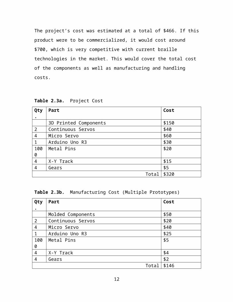
The project’s cost was estimated at a total of $466. If this product were to be
commercialized, it would cost around $700, which is very competitive with current
braille technologies in the market. This would cover the total cost of the components as
well as manufacturing and handling costs.
Table 2.3a. Project Cost
Qty. Part Cost3D Printed Components $150
2 Continuous Servos $404 Micro Servo $601 Arduino Uno R3 $301000 Metal Pins $204 X-Y Track $154 Gears $5
Total $320
Table 2.3b. Manufacturing Cost (Multiple Prototypes)
Qty. Part CostMolded Components $50
2 Continuous Servos $204 Micro Servo $401 Arduino Uno R3 $251000 Metal Pins $54 X-Y Track $44 Gears $2
Total $146
8

2.4 Gantt Chart
Project management is crucial to the success of any project. Team Five used the
Microsoft Project software to create a master schedule of milestones that must be
completed. The schedule shows the sections and sub-sections in which the project was
divided into. This allows the team to keep track of elements that are dependent on others.
Figure 2.4 shows the breakdown of the project’s timelines as well as its critical path. The
3D tactile display project started on January 28th, which was three weeks after the
projects were assigned. The project was divided into seven major sections which are:
project definition task, pre-proposal preparation, oral presentation preparation, final
proposal preparation, prototyping, full model implementation and lastly the final
presentation. As mentioned above, each section has sub-sections explaining what should
be done to achieve each milestone and their time period.
It is important to mention that Team Five was assigned a Synchronization of Sensors via
Timing Lights project sponsored by the Air-force at the beginning of the semester. Due
to unfortunate circumstances of sponsorship, Team Five was compelled to change its
project to an Electronic Braille Reader. After rigorous research conducted and
communicating with the RCPD faculty, the team concluded that this project was not
practical due to the nature of electricity. According to an article published on IEEE by a
research group from the University Nacional de San Juan, the electrical pulses generated
by an electro-tactile reader would generally be too low, to the point that they confused the
user. 50% accuracy was noticed from the experiment conducted. On the other hand,
when the electrical pulses were increased in intensity, this caused an unpleasant sensation
to the user’s fingers. This scenario resulted in an improved 85% accuracy, but was not
further pursued as the sensations were too painful to users. Due to these results, the team
decided on the 3D tactile display, sponsored by Dr. Udpa as well as the RCPD.
9
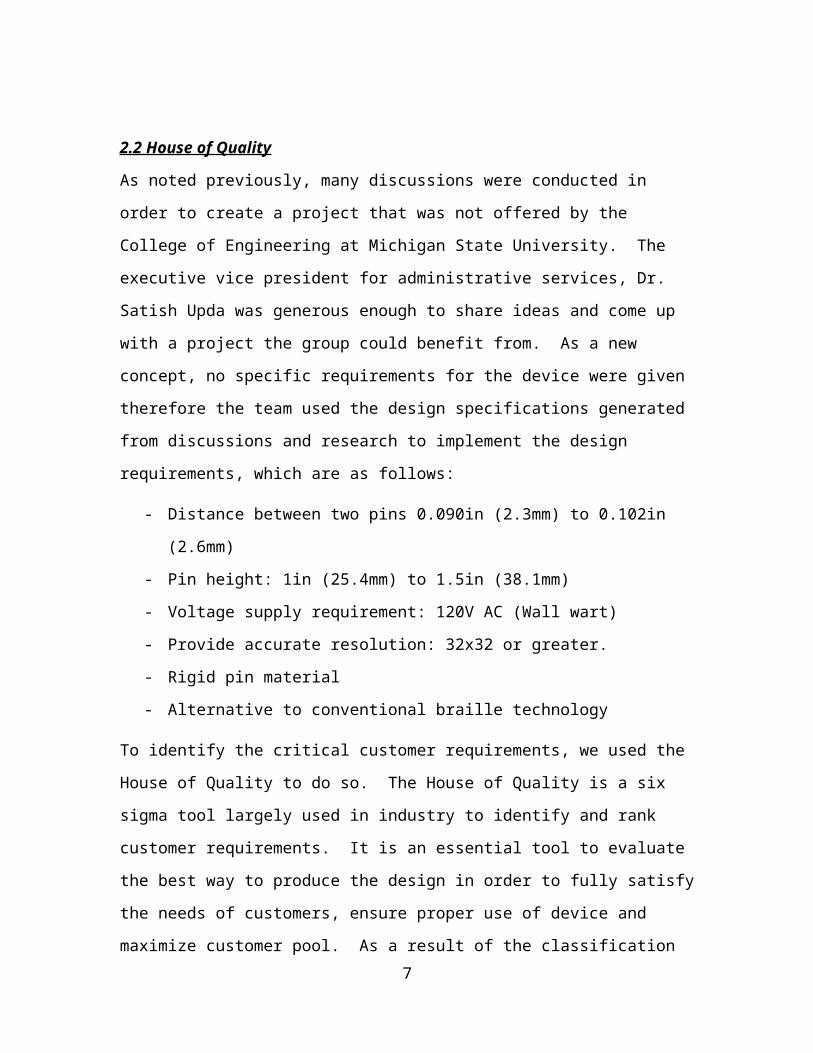
Figure 2.4. Decision Matrix Feasibility Criterion (Continued on next page)
10

Figure 2.4. Decision Matrix Feasibility Criterion (Continued)
11

Chapter 3 – Technical Descriptions
3.1 Hardware Design Efforts
The 3D refreshable tactile display hardware sections can be broken down into four main
sub-groups of efforts: Z-axis pin setter mechanism, X-Y axis table, the
pin-holder/display, and enclosure. Figure 3.1 is provided in order to better visualize the
effort creation.
Figure 3.1. Hardware Efforts Flow Chart
12

3.2 Z-Axis
The most constrained item on the 3D refreshable tactile display is the Z-Axis Mechanism.
The device had to be monitored on its height, since it would be the tallest component in
the device and could not become extremely large for aesthetic reasons. Speed was also a
major constraint since 50% of the time spent raising pins on the device would be reliant
on the Z-Axis Mechanism. And the last major constraint was scalability, since it was
desired to create a design that could be replicated multiple times in order to increase
efficiency. Several possibilities were explored in the initial brainstorming, including
linear actuators. Linear actuators proved to be very expensive and were not a good match
for the design as cost would inhibit scalability in design. Low cost 180 degree
servomotors were chosen due to their accuracy in control due to rotation feedback as well
as their speed. Rotation from 0 to 180 degrees took around 300ms, which is very
reasonable. At a price point of five dollars a motor, multiple motors can be purchased in
order to parallelize operations and increase the overall speed. Using a rotational motion
servo however, has its downsides. The design requires linear motion to push up the pins,
so the challenge became converting rotational motion into linear motion. A rack and
pinion design was chosen, since it did not require multiple turns in order to move
linearly. It also had a distance traveled that varied linearly with the rotational distance
traveled. Initial prototyping involved creating a basic guiderail in order to track and
guide the rack, as can be seen in Figure 3.2a. The platform was initially a single part, but
in order to incorporate multiple devices, it was split into two pieces, a smaller rail and a
separate holder for the servo motor (Figures 3.2b and 3.2c).
13

Figures 3.2a, 3.2b. Old rail design and new streamlined design
Figure 3.2c. Servomotor holder
14
3.3 X-Y Table
There was a need to create a device that would be able to position the Z-axis mechanism
accurately. Several ideas were considered, including another rack and pinion styled
design. The ultimate decision that was made to begin prototyping was a lead-screw
design, due to the high accuracy that was associated with it. The screw would have to
turn multiple times in order to move the platform a small distance, and this value is
adjustable by choosing the appropriate thread size on the lead-screw. Stepper motors
were considered for the design however discarded when the high cost inhibited their
purchase. High torque and high speed continuous servomotors were chosen in order to
turn the lead-screws. They were initially controlled by pulse width modulation, or the
sending of a series of pulses that would turn the shaft a specific distance. This proved to
be inaccurate during testing however, it was decided that there would need to be some
sort of feedback. A linear potentiometer was chosen for feedback. The potentiometer
reading is changed based on where pressure is applied. The potentiometer chosen was
variable up to 1024 quantized steps, giving sufficient accuracy for our design. This
allowed for the determination of precisely where along the track the Z axis platform was
and when it needed to stop and perform the pin raising maneuver.
Initial testing of the X-Y Table showed instability. The bushings on the lead-screw were
tight and did not provide sufficient flexibility which added stress to the design. However,
by using ball bearings, the friction was reduced to almost nothing, allowing for the
addition of an additional stage to the X-Y table, a second support on the axis to increase
stability. This axis is driven in parallel with the first one by a belt. The original Z
platform used two metal rods in order to prevent the platform from falling over. Since
the rods were not perfectly straight, there was a lot of play in the platform, and it was not
stable; replacing the guide rods with two wheels kept it rolling along, and proved to be a
cheap and effective solution, once secured to the platform. This design was much more
stable than the original design.
15

3.4 Pin Matrix Display
The most complex portion of hardware design in this project was actually the display
which would contain the pins. The device needed to be strong enough to hold up the pins
after being pushed up, but not so tight that the pins could not actually be pushed up. This
also led to the need for variable tightness, in which once the image is created and ready to
be handled, the pins will not easily go back down. The initial prototype included notched
pins and a 4x4 pixel display with varying hole diameters. This design was not very
effective since the pins were 3D printed and the notches wore away. They were
exchanged for metal pins and an improved prototype holding 16x16 pins. Springs were
placed in between the layers of the pin holder in order to create even tension across the
display. The new prototype introduced a new problem; since the 3D printer prints in
plastic, the plastic was flexing too much and the pins in the center of the display were too
loose and had a tendency to fall out. In the later design of a 32x32 pin display, metal
plates were placed on the ends of the display in order to accommodate for the plastic
flexing.
3.5 Enclosure
Lastly there was the enclosure. Once the final dimensions of the other components of the
project were determined, the constraints for the enclosure were set. Plexiglas was
determined to be a good material in order to show off the interior of the project and show
all the moving parts. It is also a strong and durable material. Particle board was chosen to
be the base of the 3D tactile display, since it is denser than regular wood, as well as
straighter and easier to work with. The design was then mounted to the base and placed
inside of the enclosure and prepared for final testing and calibration.
16

3.6 Hardware Implementation
Figure 3.6a shows the completed refreshable 3D tactile display. The overall design
measures 16 inches by 16 inches by 8 inches with wood base and top and Plexiglas walls
that demonstrate the inner workings of the design. The enclosure is designed to
accommodate a design that is four times the design for future scalability.
The pin matrix display can also be seen in Figure 3.6a. It is a 32 by 32 pin matrix which
is 5.5 inches by 4 inches (with extra length in the width to accommodate the bolts that
hold the plates together). The display is filled with metal pins with rounded oval tops
which have been tumbled in order to provide additional uniformity and additional
comfort while using the device. The device is operated by setting the display to a
specific tension. This tension is a rather specific value at which there is enough friction
to hold the pins up after they have been raised without falling down. The design is
several plastic ribbed slabs that accommodate the metal pins which are placed on a
threaded rod with springs in between each slab in order to help equalize the tension
between each slab. This allows for a more uniform tension on the pins and makes it
easier to adjust the display for use. The pins are raised into place from the Z mechanism
below it and once the image is finished being processed, the nuts holding the plates
together are tightened, which prevents the pins from falling down, even during use.
When the image is no longer desired, the nuts are loosened again and the pins will reset,
and the display is ready for another image.
Figure 3.6b shows the internals of the device. Here we can see the X-Y table and the Z-
axis mechanism mounted on top. The X-Y table has two identical lead-screw platforms
which are connected together in parallel via a pulley system in order to increase stability
of the X-Y table as well as reduce noise created from stress. The X-axis uses ball
bearings in order to reduce friction and allow for easier rotation and movement of the
mounted Y-axis lead-screw platform. The Y-axis device is mounted across the X-axis
platforms and positions the Z-axis mechanism. The Z-axis mechanism demonstrates the
scalability of the design by placing two pin setting racks in a parallel manner. This
allows for twice as many pins to be set in the same amount of time, and it can easily be
increased to more additional Z mechanisms in order to further increase the speed of
operation. Holders were designed for the servo motors in order to be removable and
17

replaceable. In order to create a more robust design, this is crucial since if a servomotor
fails, it can easily be replaced without having to worry about glue or taking the device
apart. It rests right on top and can easily be accessed once the lid is opened.
Figure 3.6a. Completed Refreshable 3D Tactile Display
18

Figure 3.6b. Internal View of 3D Tactile Display
3.7 Software Implementation
The software portion of the project was separated into two different parts, software
coding in C++ and hardware coding in Processing/Arduino IDE. The ideal solution was
to write all of the code in Processing/Arduino, but the complex image processing libraries
were only compatible with C++. The first part of the semester was focused on creating
the software portion, and the second part was focused on hardware coding.
Software Portion
The software section involved creating the image and text processing part of the program.
The program was created on a linux-based system with the Open Source Computer
Vision library (OpenCV). OpenCV library included many of the complex image
manipulating tools we required such as converting to gray scale and resizing the image.
Source Code Files (Included in the Appendix):
Main.cpp – Entry point of the program. Handles inputs from user, and directs the
program to correct type (image or text).
19
Image.cpp – Image processing of the input file, converts the image into a 2D array
of pin heights.
Image.h – Header file of Image.cpp.
Text.cpp – Text processing of the input file, converts letters into braille then sets
the appropriate pins for the 2D array.
Text.h – Header file of Text.cpp.
Braille.cpp – Braille class that handles conversion of letters into braille and braille
to letters.
Braille.h – Header file of Braille.cpp
makefile – Makefile of software portion
The program entry point Main.cpp handles all of the input given from the user and directs
the file path to Image.cpp for images and Text.cpp for text files. The input prompt loops
until a valid file type and file path is given.
The image processing is handled by Image.cpp and Image.h. The algorithm starts by
processing the image into a local image matrix, and then converts the image into a gray
scale. The image is normalized to create the widest range of pixel intensity values, and
then resized into the pin matrix size. The last step converts the pixel intensities to the
corresponding height interval defined in the program and outputs the values into
output.txt. Figure 3.7a shows an example execution of an image file.
Defined variables in Image.h:
XPINS – Number of pins for the X-axis
YPINS – Number of pins for the Y-axis
ZHEIGHT – Number of height intervals for the pin matrix
20

MAXINT – Maximum pixel intensity of images
Figure 3.7a. Software Processing of an Image File
The text processing is handled by Text.cpp and Text.h. The code starts off by reading the
entire text file into a string. The number of rows and the number of letters in each row
are determined by the size of the matrix defined in Image.h and also the
horizontal/vertical spacing defined in Text.h. The letters of the string are read one by
one, converted into Braille (Braille.cpp/Braille.h), and then written into the 2D array.
The 2D array defaults raised pins as a height of one and writes the array values into
output.txt.
Defined variables in Text.h:
VSPACING – Number of pin rows to skip vertically
HSPACING – Number of pin columns to skip horizontally for letters
To run the program, install OpenCV (http://opencv.org/downloads.html) on a linux-based
system, then navigate to the source folder of the project files. Execute ‘make’ then run
21

‘./ece480dt5’ to start the program. The first input argument is the input file type (image
or text), and the second argument is the location of the file based on the executable
(ece480dt5) or a full system path is also accepted. After the two valid inputs are taken,
the program will create a 2D array output text file in the same directory as the executable.
The output text file will then be passed to the hardware portion of the code to
appropriately move the servos to the defined heights.
Hardware Portion
The Arduino Uno Revision 3 microcontroller was used to control the servos and linear
actuators in our project. The Arduino/Processing IDE continues where the software
processing left off to control the XY table and Z-axis pin raising mechanism.
Source Code File (Included in the Appendix):
ServoControl.pde (Figure 3.7b) – Reads the output text file from the image/text
processing, then moves the XY table and Z-mechanism to raise the pins to the
corresponding height.
22

Figure 3.7b. Screenshot of ServoControl Program
The Processing program starts by storing the pin heights gathered from the image/text
processing portion (output.txt) into a local 2D array (function - processimage). The pin
raising is achieved with a state machine. In the Reset state, the X and Y-axis servos are
instructed to move until they reach the starting position via feedback from the linear
potentiometers. Once the table is reset the state machine is put into a Ready state, where
inside it loops between raising the pin with the Z-axis mechanism and moving to the next
pin. The Z-axis mechanism raises the pin based off of the pin height defined from the
software portion. Upon testing, the servos that were used for the Z-axis had roughly 120
degrees of movement instead of the 180 degrees defined in the specs. To solve this issue,
the global variables minAngle and maxAngle control the lowest and highest angle the
servo can rotate. The function update() is called for each pin and controls the location of
the Z-axis and the 2D array index. Once the last pin is printed, the program exits.
23

Arduino Pin-Outs
Digital Pin 7 : Control first Z-axis mechanism
6 : Control second Z-axis mechanism
5 : Control X-axis movement
4 : Control Y-axis movement
Analog Pin A0: Location feedback of X-axis via linear potentiometers
A1: Location feedback of Y-axis via linear potentiometers
Power 5V: Power for Z-axis servos and linear potentiometers
GND: Ground
Figure 3.7c. Standard Firmata For Processing IDE and Arduino Interface
24
To run the program, install Arduino IDE (http://arduino.cc/en/main/software) and
Processing IDE (https://processing.org/download/?processing). The Arduino Standard
Firmata (Figure 3.7c) was used to communicate from Processing IDE to the Arduino Uno
microcontroller. Connect the Arduino Uno with the serial connector then upload the
Standard Firmata to the Arduino by opening Arduino IDE then selecting File>
Examples> Firmata> StandardFirmata, then clicking Upload. The next step is to open
Processing IDE and then selecting the Arduino/Processing> ServoControl>
ServoControl.pde file from the project directory. Provide an output.txt file from the
software portion and place the file in the root project directory, and then click on Upload.
The complete software and hardware code can be executed by running the shell script file
run.sh. The script compiles the C++ code, runs the executable, executes the processing
code, removes the output.txt, and then finally cleans the source folder (The file location
required for the image/text processing portion is a path relative from the root directory of
the project).
25

Chapter 4 – Test DataOur design consisted of a few different major components, including the X-Y table, the
Z-axis raising mechanism, the variable-grip grid of pins, and the software processing of
an image. During the prototype stages of the design, each of these sections were both
built and tested individually. Once each of the individual components was complete and
functional, we assembled the parts into our final design; this is where the majority of the
testing for our project took place.
In order to test the functionality of the design, we fed an image into the tactile display and
recorded what happened. The software worked flawlessly, as it had already been finished
during the individual section; the image of an apple was converted to a grayscale image,
and the corresponding pin heights were generated. Individually, the X-Y table and the Z-
axis pin-raiser had both functioned well; when the two parts were coupled together they
generally worked well, with an acceptable level of precision and repeatability. The X-Y
table would maneuver the Z-mechanism into place, which would then push a pin up, and
rotate back down; from there the process simply repeated for every pin in the image.
Initially when we tested the design, some of the pins, after being raised to the desired
height, fell back down into the lowest position. Overall though, the initial test functioned
well, with the general shape of the image showing up on the grid and at the desired
heights.
The two largest problems we faced were that occasionally pins would slip back down,
and that occasionally the pin raising mechanism would hit neighboring pins or no pins at
all. In order to solve the former problem, the tightness of the locking mechanism was
increased, until very few pins still slipped out, which we deemed as successful since the
full grid contained over a thousand pins. In order to solve the second problem, in which
incorrect pins were occasionally raised, an enclosure was built to keep the pin-grid firmly
in place. When designing this enclosure, we ran into another problem; the wood panel
we used to house the grid was flexible, allowing the grid to shift slightly under pressure.
This was improved by attaching metal cross-braces to the underside of the panel,
preventing this unwanted flexing. Overall, the final design functioned much as we hoped
it would, with a minor but acceptable amount of error; therefore, we believe our overall
project to be successful.
26
Chapter 5 – Final Cost, Schedule, Summary, and Conclusions
5.1 Summary
The project was an overall success. Team five constructed a 3D tactile display that can
display images and Braille. We were able to implement a working X-Y table, Z-axis pin
raising mechanism, pin matrix display, and software. The team was able to work
successfully together without any major disputes. We were able to apply our problem
solving techniques we acquired at Michigan State University to solve difficult issues. The
project was done on time and within the $500 budget. The semester was a continual
learning process, and we were able to fulfill all of the learning objectives defined for the
senior capstone class.
5.2 Success and Failures
The largest success of the project was getting a product that actually functioned with all
of the different parts. From earlier on in the project, we were set on creating all of the
major components without purchasing them (X-Y table, Z-axis mechanism, etc.) to save
on cost. Due to this restriction, the project was very complicated.
One of the failures was the pin matrix display having uneven pressure against the pins.
We were able to get roughly 60-70% of the pins to hold their position, but had problems
with pins being held too tightly or being completely loose.
5.3 Suggestions for the Future
There are improvements that could be made in future revisions. The number of servos
driving the pins could be increased to raise the pins at a faster pace. Due to budget
constraints we were only able to implement two Z-axis mechanisms for our project. In
future revisions, the pin matrix display could have servos controlling the tension of the
bolt/nut assembly for automation. Lastly, the pin matrix display needs improvement so
that the pressure on the pins is equal. More research is required with what 3D printer
material will work best, as well as what type of pins would provide the best accuracy.
27

5.4 Final Schedule
The final schedule was executed as shown in the Gantt Chart (Figure 2.4).
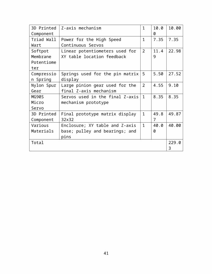
5.5 Final Budget
Table 5.5a. Actual CostsProduct Description Qty Price
/perTotal
Arduino Uno R3
Microcontroller to control the servos 1 28.57 28.57
Futaba S148 Prototype servos to control the XY table 2 14.00 28.00
Micro Servo Prototype servo to control the Z-axis mechanism
1 9.95 9.95
Nylon Spur Gear
Pinion gear used for Z-axis mechanism 1 4.12 4.12
Nylon Gear Rack
Rack used for the Z-axis mechanism 1 4.78 4.78
High Speed Continuous Servo
Final prototype servos to control the XY table 2 16.99 33.98
3D Printed Component
Prototype pin matrix display 1 44.00 44.00
3D Printed Component
Z-axis mechanism 1 20.00 20.00
Triad Wall Wart
Power for the High Speed Continuous Servos 1 9.19 9.19
Arduino Mega 2560 R3
Microcontroller that was to be used to control the servos and linear potentiometers
1 46.95 46.95
Softpot Membrane Potentiometer
Linear potentiometers used for XY table location feedback
2 14.36 28.72
Compression Spring
Springs used for the pin matrix display 5 6.88 34.40
Nylon Spur Gear
Large pinion gear used for the final Z-axis mechanism
2 5.69 11.38
MG90S Micro Servo
Servos used in the final Z-axis mechanism prototype
1 20.88 20.88
3D Printed Component
Final prototype matrix display 32x32 1 99.73 99.73
Shipping 43.82Total 487.71
28

Table 5.5b. Manufacturing Cost per Unit
Product Description Qty Price/per
Total
Arduino Uno R3
Microcontroller to control the servos 1 22.86 22.86
Nylon Gear Rack
Rack used for the Z-axis mechanism 1 3.82 3.82
High Speed Continuous Servo
Final prototype servos to control the XY table 2 13.59 27.18
3D Printed Component
Z-axis mechanism 1 10.00 10.00
Triad Wall Wart
Power for the High Speed Continuous Servos 1 7.35 7.35
Softpot Membrane Potentiometer
Linear potentiometers used for XY table location feedback
2 11.49 22.98
Compression Spring
Springs used for the pin matrix display 5 5.50 27.52
Nylon Spur Gear
Large pinion gear used for the final Z-axis mechanism
2 4.55 9.10
MG90S Micro Servo
Servos used in the final Z-axis mechanism prototype
1 8.35 8.35
3D Printed Component
Final prototype matrix display 32x32 1 49.87 49.87
Various Materials
Enclosure; XY table and Z-axis base; pulley and bearings; and pins
1 40.00 40.00
Total 229.03
29

Appendix 1 – Technical Roles
Steven Chao - As the lab coordinator, my main responsibilities were to place orders with
vendors, to compare prices from different suppliers, and to pick up the parts after they
shipped. Due to the fact that everyone used the lab to work on their individual
components, I didn’t have many responsibilities in regards to managing their lab work.
At first, when we were designing our project, one of my major responsibilities was to get
quotes on components we were looking at. This included calling to get prices on small
commercial X-Y tables and also high-speed, precision servomotors. In both cases the
prices were well outside of our budget (cheap X-Y tables being around $700 and the
precision servomotors costing around $150). This is why we ended up developing our
own versions of both features.
As people began work on their individual components, they would send a link of any
individual parts that they would need. I would then shop around to try to find the lowest
available price from different vendors. I would then place an order to the ECE shop, who
would make the official order, using the funds from our group’s total budget. Finally, as
the orders came in, I would be responsible for picking them up, verifying the order,
placing them in our group locker, and notifying the relevant parties.
Kodai Ishikawa – The technical role that I played on this project was software integration
and construction of the XY table. The software integration part was separated into two
different phases, the software programming portion and the hardware-programming
portion. The software programming I created was an image and text algorithm that would
take an input image/text and convert it into a 2D matrix of heights based on the size of
the pin matrix display. The second phase was the hardware-programming phase, where I
created a program in Processing/Arduino that would continue where the software portion
left off. The Processing code created took the 2D array output from the software portion
and moved the servos appropriately to raise each pin. I created a script that would run the
software program and then run the hardware program through command line. By the end
30

of the semester, I had learned how to create a program with the OpenCV Image/Video
library and learned two new languages Arduino and Processing.
The other role I had was to create the XY table to move the Z-mechanism to each pin.
We chose to create the XY table instead of buying one to save on cost since commercial
products cost roughly $400. The design consisted of a lead screw moving the platform
with guide rods keeping the platform flat. The XY table was constructed from materials
gathered from Home Depot and Lowes, and the movement was controlled by two
continuous servos. Stephen Blosser and our team refined the first prototype design, and
we were able to create a more precise and smoother movement.
Lastly, every member of the team including myself helped constructing the final product
and debug any problems we ran into after assembling the final product. Since we did not
have a designated debugger or tester, everyone in the team was present for the fine-tuning
work that had to be done.
Daniel Olbrys - Daniel’s position on the team was varied throughout the project. From
the beginning, Daniel assisted with writing the executive summary of the project.
Creating a thorough understanding of the project was a crucial step that needed to be
completed in order to create an effective schedule with corresponding time line, as well
as begin the constraint formulation and determine the design specifications. Daniel
played a crucial role in formulating constraints for design. He helped determine the
limiting factors that would allow a device to still be usable, and helped to build around it.
It was determined that key constraints on the device were the size of the pin matrix, size
of the physical device, speed, and durability. All of the key constraints were intertwined
and affected each other, for example, the pin matrix would limit the speed of the device
as well as how large the device would be. Daniel also assisted with developing design
specifications, including the 32 by 32 pin matrix, limited height design, and scalable
design. The project was identifiable by three key parts: the X-Y Table, the pin matrix
display, and the Z-axis pin setting mechanism. Daniel’s main role applied to the design
and production of the Z-axis portion of the project. Several pin setting designs were
explored, but the necessity for linear motion was confirmed. Linear actuators are
commercially available, but since stability is key aspect that the group wanted to address,
31

expensive linear actuators weren’t a very good solution. Daniel helped in coming up
with the reciprocating motion scheme that was effective. Rack and pinion was chosen
since it converted rotational motion into linear motion with a linear scaling factor, which
is an advantage over a piston style system or cam. Daniel assembled the gear guiding
racks and produced holders for the servomotors which were producing the motion to set
the pins. Daniel also helped with general troubleshooting over the final designs of the
project.
Terry Pharaon - The technical role I played in the project was mainly designing and
building the outside enclosure of the device. The first step was to find out which
enclosure would be the most practical for the project. It entailed finding the proper
resources, tools and material to use to create the enclosure. During the brainstorming
process, I learned how to use modelling software. I desigsned 3D model of the enclosure
using the Siemens NX 8.5 software to present the idea to the rest of the team. This model
was solely use as a mock of the actual product. Taking proper measurements was crucial
to the development of the enclosure. It strongly depended on the size of the actual device
when assembled, therefore depended on the work of the other members of the team. After
few considerations and material testing (drilling, cutting, shearing and bending),
Plexiglas and wood were used since it is very easy to work with and assemble such
materials. I took a brief training session which allowed me to use the mechanical
engineering equipment to cut the material. I also thought it important to have proper
spacing for wiring such that it would not interfere with the mechanical moving parts of
the device. The enclosure was designed such that the parts of the mechanics parts were
accessible as needed in case of any issues.
Other than that, I also had a role in the design concept on the pin support and locking
system of the product. I also participated in other task that in which support was needed.
Lastly I contributed to the technical documentations of the project including the proposal,
design issues paper, technical presentation, and the final report.
32

Michael Wang – My technical portion of the overall project was defined as leading and
participating in the computer aided design (3D Printed Components) and Z-Axis (raising
pins) assembly. I did the majority of the work in designing the 3D printed display matrix.
This was a critical portion of the design, and it was from working with initial prototypes
where our team was able to draw a significant amount of constraints and design criterion.
Cost was a major constraint throughout the entire process. The final 32x32 display
matrix ended up costing approximately $100 to 3D print – this was perhaps the greatest
factor in limiting our display size.
In addition to designing the 3D printed display matrix, I also assisted with nearly every
other aspect of the device design as well. The initial Z-axis mechanism was designed by
other members of the team, but I was involved in the redesign and optimization (reducing
the size of the assembly to enable further expandability and functionality) of said design.
Furthermore, I was also instrumental in the design of the XY-table itself, by discovering
the feedback mechanism that we ended up using (membrane-based linear
potentiometers). I also helped to refine and revise the design of the XY-table after initial
prototyping.
I have learned a great deal about the overall engineering design process. In fact, I
literally went through the engineering design process. I, along with my team members,
had to use many key tools throughout the engineering design process, which include, but
are not limited to: specific task-oriented software (Microsoft Project, Siemens NX, etc.),
as well as the tool of problem solving.
33
Appendix 2 – References
A-Z to Deafblindness. Refreshable Braille Displays. 2014.
http://www.deafblind.com/display.html
American Foundation for the Blind. Refreshable Braille Display. 2014.
http://www.afb.org/info/living-with-vision-loss/for-job-seekers/careerconnect-virtual-
worksites/retail-worksite-for-blind-users/refreshable-braille-display-3652/12345
Deane Blazie. Refreshable Braille Now and in the Years Ahead. 2014.
https://nfb.org/Images/nfb/Publications/bm/bm00/bm0001/bm000110.htm
Electrocutaneous Stimulation System for Braille Reading. Engineering in Medicine and
Biology Society (EMBC). 2010. http://ieeexplore.ieee.org/xpl/articleDetails.jsp?
arnumber=5627501
HumanWare. Braille Displays. 2014.
http://www.humanware.com/en-usa/products/blindness/braille_displays
Itseez. Open Source Computer Vision. 2014. http://opencv.org/
Microsoft. Basic Tasks in Project. 2013. http://office.microsoft.com/en-us/project-
help/basic-tasks-in-project-2013-HA102891709.aspx
Rob Ives. Reciprocating Motion. 2010.
http://www.robives.com/mechanisms/recip#.UwenyU2A1Hh
Specification 800: Braille Books and Pamphlets. National Library Service for the Blind
and Physically Handicapped, Library of Congress. 2008.
www.loc.gov/nls/specs/800_march5_2008.pdf
34

Appendix 3
============================ CODE ==============================//// ECE480_3DBraille// main.cpp//// Created by Kodai Ishikawa on 2/22/14.// Copyright (c) 2014 Kodai Ishikawa. All rights reserved.//
#include <iostream>#include <string>
#include "Image.h"#include "Text.h"
using namespace std;
int main(int argc, const char * argv[]){ int image[XPINS][YPINS];
cout << "/////////////////////////////////////////////////////////////" << endl;cout << "/ ECE480 Team 5 - 3D Braille Display - Software C++\t /" << endl;cout << "/ \t\t\t\t\t\t\t /" << endl;cout << "/ Copyright (c) 2014 Kodai Ishikawa. All rights reserved. /" << endl;cout << "/////////////////////////////////////////////////////////////\n" << endl;
while(1) { string mode, filename; cout << "Enter input file type (image or text): "; cin >> mode; if(mode=="image") { while(1) //Loop until valid image input { cout << "------------------------------------------------" << endl; cout << "Enter image location (Full or Relative Path)" << endl; cout << "Ex. tests/gradient01.png" << endl << "> "; cin >> filename; cout << endl;
35

if(ProcessImage(filename.c_str(),image)) { break;
} else cout << "ERROR: Could not open or find the image '" << filename << "'." << endl << endl << endl; } break; } else if(mode=="text") { while(1) //Loop until valid text file input { cout << "------------------------------------------------" << endl; cout << "Enter text file location (Full or Relative Path)" << endl; cout << "Ex. tests/hello.txt" << endl << "> "; cin >> filename; cout << endl; if(ProcessText(filename.c_str(),image)) { break; } else cout << "ERROR: Could not open or find the text file '" << filename << "'." << endl << endl << endl; } break; } else if(mode=="exit") { exit(1); } else { cout << "Invalid input" << endl << endl; } }
return 0;}
36

//// ECE480_3DBraille// Image.h//// Created by Kodai Ishikawa on 2/22/14.// Copyright (c) 2014 Kodai Ishikawa. All rights reserved.//
#ifndef ____Image__#define ____Image__
#include <opencv2/core/core.hpp>#include <opencv2/highgui/highgui.hpp>#include <opencv2/imgproc/imgproc.hpp>#include <iostream>#include <cstdlib>#include <cmath>#include <string>#include <fstream>
#define XPINS 32 //Number of pins (X axis)#define YPINS 32 //Number of pins (Y axis)#define ZHEIGHT 10 //Number of height intervals#define MAXINT 255 //Maximum pixel intensity
using namespace cv;using namespace std;
bool ProcessImage(const char *filename,int (&heightMatrix)[XPINS][YPINS]);void DisplayImage(string title, Mat image);void PrintMatrix(string title, int (&matrix)[XPINS][YPINS]);
#endif /* defined(____Image__) */
37

//// ECE480_3DBraille// Image.cpp//// Created by Kodai Ishikawa on 2/22/14.// Copyright (c) 2014 Kodai Ishikawa. All rights reserved.//
#include "Image.h"
bool ProcessImage(const char *filename,int (&heightMatrix)[XPINS][YPINS]){
bool displayImgs = true; //Display Images?bool pixelInt = true; //Print pixel intensitiesbool zHeight = true; //Print Z heights
Size displaySize(XPINS,YPINS); //Set pin matrix size cout << "Pin Matrix Size: " << XPINS << "x" << YPINS << endl << endl; /* Process input image */ cout << "Processing image.."; Mat inputImage = imread(filename, CV_LOAD_IMAGE_COLOR); if(!inputImage.data) { cout << endl; return false; } cout << "\t\tComplete" << endl;
if(displayImgs) DisplayImage("Input Image", inputImage); /* Convert input image to grayscale */ cout << "Converting to Grayscale.."; Mat grayscaleImage; cvtColor(inputImage, grayscaleImage, CV_BGR2GRAY); //Grayscale inputImage.release(); cout << "\tComplete" << endl;
if(displayImgs) DisplayImage("Grayscale Image", grayscaleImage); /* Normalize grayscale image */ cout << "Normalizing Image.."; Mat normalizedImage;
38

equalizeHist(grayscaleImage,normalizedImage); //Normalize grayscaleImage.release(); cout << "\t\tComplete" << endl;
if(displayImgs) DisplayImage("Normalized Image", normalizedImage); /* Resize normalized image to pin matrix size */ cout << "Resizing Image.."; Mat resizedImage; resize(normalizedImage, resizedImage, displaySize); //Resize normalizedImage.release(); cout << "\t\tComplete" << endl;
if(displayImgs) DisplayImage("Resized Image", resizedImage); /* Convert image into 2D array(pixel intensities and Z height) */ int imageMatrix[XPINS][YPINS];
double interval = (float)MAXINT/(ZHEIGHT); for(int i=0;i<resizedImage.rows;i++) { for (int j=0;j<resizedImage.cols;j++) { imageMatrix[i][j] = MAXINT - int(resizedImage.at<unsigned char>(i,j)); //Invert pixel intensity heightMatrix[i][j] = (int)floor(imageMatrix[i][j]/interval); } }
if(pixelInt) PrintMatrix("Image Pixel Intensities", imageMatrix);if(zHeight) PrintMatrix("Z Axis Pin Heights", heightMatrix);
ofstream outputFile; outputFile.open ("output.txt"); if(outputFile.is_open()) { for(int i=0;i<XPINS;i++) { for (int j=0;j<YPINS;j++) { outputFile << heightMatrix[i][j] << "\t"; } outputFile << endl; }
39

} else { return false; } resizedImage.release();
return true;}
/* Displays image, destroys window on key press */void DisplayImage(string title, Mat image){ imshow(title, image); waitKey(); destroyWindow(title);}
/* Prints 2D matrix */void PrintMatrix(string title, int (&matrix)[XPINS][YPINS]){
cout << endl << title << " - " << XPINS << "x" << YPINS << endl << endl; for(int i=0;i<XPINS;i++) { for (int j=0;j<YPINS;j++) { cout << matrix[i][j] << "\t"; } cout << endl << endl; }}
40

//// ECE480_3DBraille// Text.h//// Created by Kodai Ishikawa on 2/22/14.// Copyright (c) 2014 Kodai Ishikawa. All rights reserved.//
#ifndef ____Text__#define ____Text__
#include <iostream>#include <fstream>#include <string>#include <cstdlib>#include <cmath>#include "Braille.h"#include "Image.h"
#define VSPACING 4#define HSPACING 2#define VREMAIN 3#define HREMAIN 2
using namespace std;
bool ProcessText(const char *filename,int (&heightMatrix)[XPINS][YPINS]);
#endif /* defined(____Text__) */
41

//// ECE480_Text// Text.cpp//// Created by Kodai Ishikawa on 2/22/14.// Copyright (c) 2014 Kodai Ishikawa. All rights reserved.//
#include "Text.h"
bool ProcessText(const char *filename,int (&heightMatrix)[XPINS][YPINS]){
Braille *braille = new Braille(); bool zHeight = true; //Print Z heights /* Open the file */ ifstream txtFile; txtFile.open(filename); if(!txtFile.is_open()) { return false; } /* Read in entire file into a string */ string text; text.assign(istreambuf_iterator<char>(txtFile),istreambuf_iterator<char>()); int rows = YPINS/(VSPACING+3); int letters = XPINS/(HSPACING+2); if(YPINS%(VSPACING+3)==VREMAIN) rows++; if(XPINS%(HSPACING+2)==HREMAIN) letters++; /* Zero the height matrix */ for(int i=0;i<XPINS;i++) { for (int j=0;j<YPINS;j++) { heightMatrix[i][j] = 0; } } cout << "Pin Matrix Size: " << XPINS << "x" << YPINS << endl; cout << "Number of Rows: " << rows << endl; cout << "Number of Letters per Row: " << letters << endl << endl;
42

/* Convert each letter to braille then input into the height matrix */ int index = 0; for(int j=0;j<rows;j++) { for(int i=0;i<letters;i++) { if(index<text.length()) //Check EOF { heightMatrix[j*(VSPACING+3)][i*(HSPACING+2)]=(braille->GetBraille(string(1,text[index]))[0])-'0'; heightMatrix[j*(VSPACING+3)+1][i*(HSPACING+2)]=(braille->GetBraille(string(1,text[index]))[1])-'0'; heightMatrix[j*(VSPACING+3)+2][i*(HSPACING+2)]=(braille->GetBraille(string(1,text[index]))[2])-'0'; heightMatrix[j*(VSPACING+3)][i*(HSPACING+2)+1]=(braille->GetBraille(string(1,text[index]))[3])-'0'; heightMatrix[j*(VSPACING+3)+1][i*(HSPACING+2)+1]=(braille->GetBraille(string(1,text[index]))[4])-'0'; heightMatrix[j*(VSPACING+3)+2][i*(HSPACING+2)+1]=(braille->GetBraille(string(1,text[index]))[5])-'0'; index++; } } } if(zHeight) { cout << "Z Axis Pins - " << XPINS << "x" << YPINS << endl << endl;; for(int i=0;i<XPINS;i++) { for (int j=0;j<YPINS;j++) { if(heightMatrix[i][j]==0) cout << ".\t"; else cout << "X\t"; } cout << endl; } }
return true;}
43
//// ECE480_3DBraille// Braille.h//// Created by Kodai Ishikawa on 2/22/14.// Copyright (c) 2014 Kodai Ishikawa. All rights reserved.//
#ifndef ____Braille__#define ____Braille__
#include <iostream>#include <string>#include <map>#include <iterator>
using namespace std;
class Braille{public:
Braille();
string GetSymbol(string dots);string GetBraille(string symbol);
private:map<string, string> BrailleTable;
};
#endif /* defined(____Braille__) */
44

//// ECE480_3DBraille// Braille.cpp//// Created by Kodai Ishikawa on 2/22/14.// Copyright (c) 2014 Kodai Ishikawa. All rights reserved.//
#include "Braille.h"
Braille::Braille(){
BrailleTable["a"]="100000";BrailleTable["b"]="110000";BrailleTable["c"]="100100";BrailleTable["d"]="100110";BrailleTable["e"]="100010";BrailleTable["f"]="110100";BrailleTable["g"]="110110";BrailleTable["h"]="110010";BrailleTable["i"]="010100";BrailleTable["j"]="010110";BrailleTable["k"]="101000";BrailleTable["l"]="111000";BrailleTable["m"]="101100";BrailleTable["n"]="101110";BrailleTable["o"]="101010";BrailleTable["p"]="111100";BrailleTable["q"]="111110";BrailleTable["r"]="111010";BrailleTable["s"]="011100";BrailleTable["t"]="011110";BrailleTable["u"]="101001";BrailleTable["v"]="111001";BrailleTable["w"]="010111";BrailleTable["x"]="101101";BrailleTable["y"]="101111";BrailleTable["z"]="101011";
BrailleTable["number"]="001111";BrailleTable["1"]="100000";BrailleTable["2"]="110000";BrailleTable["3"]="100100";BrailleTable["4"]="100110";BrailleTable["5"]="100010";BrailleTable["6"]="110100";
45

BrailleTable["7"]="110110";BrailleTable["8"]="110010";BrailleTable["9"]="010100";BrailleTable["0"]="010110";
BrailleTable["uppercase"]="000001";}
string Braille::GetSymbol(string dots){ for (map<string,string>::iterator it = BrailleTable.begin(); it != BrailleTable.end(); ++it) { if (it->second == dots) { return it->first; } }
return "";}
string Braille::GetBraille(string symbol){
return BrailleTable.find(symbol)->second;}
46

/* * Servocontrol */
// Use the included processing code serial libraryimport processing.serial.*; import cc.arduino.*;
Arduino arduino; //creates arduino object
int servo1Pin = 7;int servo2Pin = 6;int servo3Pin = 5;int servo4Pin = 4;int pot1Pin = 0;int pot2Pin = 1;int servo3stop = 94;int servo4stop = 95;
boolean reset, ready, printZ, done;boolean forwardx, backwardx;boolean forwardy, backwardy;int xlocation, ylocation;int xindex, yindex;boolean latch, hold;
int xpins = 32;// Number of x pinsint ypins = 32; // Number of y pinsint pinIntervals = 10; // Number of height intervalsint pinDist = 14; // X-Y distance between pinsint minAngle = 30;int maxAngle = 150;int[][] imageMatrix = new int[xpins][ypins];
void setup() { println(Arduino.list()); // List COM-ports
// Initiate Arduino object and declare servos arduino = new Arduino(this, Arduino.list()[4], 57600); arduino.pinMode(servo1Pin, Arduino.SERVO); arduino.pinMode(servo2Pin, Arduino.SERVO); arduino.pinMode(servo3Pin, Arduino.SERVO); arduino.pinMode(servo4Pin, Arduino.SERVO); // Declare booleans
47

reset = true; ready = false; done = false; forwardx = false; backwardx = false; forwardy = false; backwardy = false; latch = true; hold = false; printZ = false; xlocation = 646; ylocation = 406; arduino.servoWrite(servo1Pin,maxAngle); // Counter clockwise to positive arduino.servoWrite(servo2Pin,minAngle); delay(500); println("/////////////////////////////////////////////////////////////"); println("/ ECE480 Team 5 - 3D Braille Display - Hardware Processing /"); println("/\t\t\t\t\t/"); println("/ Copyright (c) 2014 Kodai Ishikawa. All rights reserved. /"); println("/////////////////////////////////////////////////////////////\n"); processimage(); print("Resetting XY Table..\t\t\t");}
void draw(){ // Set servos to default position arduino.servoWrite(servo3Pin,servo3stop); arduino.servoWrite(servo4Pin,servo4stop); // Read linear potentiometer position int readPot1 = arduino.analogRead(pot1Pin); int readPot2 = arduino.analogRead(pot2Pin); // Reset table to origin if(reset) { // Move X-axis to origin if(readPot1>xlocation) {
48

arduino.servoWrite(servo3Pin,(servo3stop-15)); } else if (readPot1<=xlocation) { arduino.servoWrite(servo3Pin,servo3stop); } // Move Y-axis to origin if(readPot2>ylocation) { arduino.servoWrite(servo4Pin,(servo4stop+15)); } else if (readPot2<=ylocation) { arduino.servoWrite(servo4Pin,servo4stop); } // X-axis and Y-axis at origin, ready to print if(reset && readPot1<=xlocation && readPot2<=ylocation) { print("Complete\n"); println("Raising pins.."); reset = false; ready = true; delay(1000); printZ = true; } } // Ready to print if(ready) { // Raise Z-axis pins then update index if(printZ && !forwardx && !backwardx && !forwardy && !backwardy) { printZ = false; print("Raising X:" + (xindex+1) + " Y:" + (yindex+1) + " and X:" + (xindex+17) + " Y:" + (yindex+1) + "\t\t"); // RAISE PIN arduino.servoWrite(servo1Pin,(maxAngle-((maxAngle-minAngle)/pinIntervals)*imageMatrix[xindex][yindex]));
49

arduino.servoWrite(servo2Pin,(minAngle+((maxAngle-minAngle)/pinIntervals)*imageMatrix[xindex+16][yindex])); if(imageMatrix[xindex][yindex] != 0) delay(400); // LOWER PIN arduino.servoWrite(servo1Pin,maxAngle); arduino.servoWrite(servo2Pin,minAngle); print("Complete\n"); if(imageMatrix[xindex][yindex] != 0) delay(500); if(update()==false) { noLoop(); } } // Control the movement of the X-axis (Pin-to-Pin movement) if(forwardx && readPot1>xlocation) { arduino.servoWrite(servo3Pin,(servo3stop-15)); } else if(backwardx && readPot1<xlocation) { arduino.servoWrite(servo3Pin,(servo3stop+15)); } else if((forwardx && readPot1<=xlocation) || (backwardx && readPot1>=xlocation)) { forwardx = false; backwardx = false; printZ = true; arduino.servoWrite(servo3Pin,servo3stop); } // Control the movement of the Y-axis (Pin-to-Pin movement) if(forwardy && readPot2>ylocation) { arduino.servoWrite(servo4Pin,(servo4stop+15)); } else if(backwardy && readPot2<ylocation) { arduino.servoWrite(servo4Pin,(servo4stop-15)); } else if((forwardy && readPot2<=ylocation) || (backwardy && readPot2>=ylocation)) { forwardy = false; backwardy = false;
50

printZ = true; arduino.servoWrite(servo4Pin,servo4stop); } } //println("Pot1: " + readPot1); println("Pot2: " + readPot2); //println("xlocation: " + xlocation); println("ylocation: " + ylocation);}
// Update location of Z-Axis and array indexboolean update(){ if(xindex==(xpins/2) && yindex==ypins) { return false; } // Update X-axis array index and command corresponding movement if(xindex<xpins/2-1 && (yindex==0 || yindex%2==0)) // Movement away from X-axis servo { xindex++; latch = false; if(xindex==xpins/2-1) { hold = true; } backwardx = true; } else // Movement towards X-axis servo { if((xindex==xpins/2-1 && latch==false) || (xindex==0 && latch==false)) // Latch first and last pin { latch = true; hold = false; } else { xindex--; latch = false; if(xindex==0) { hold = true;
51

} forwardx = true; } } // Update Y-axis array index and command corresponding movement if(((xindex==(xpins/2-1) && (yindex==0 || yindex%2==0)) || (xindex==0 && (yindex!=0 && yindex%2==1))) && !hold) { yindex++; backwardy = true; } printZ=true; // Ready to print Z axis // Calculate X-axis and Y-axis potentiometer distances xlocation = 646+xindex*pinDist; ylocation = 315+yindex*pinDist; return true;}
// Process output file input into a local 2D arrayvoid processimage(){ print("Processing input file..\t\t"); // Load output file String[] lines = loadStrings("../../output.txt"); if(ypins!=lines.length) { println("Output file number of Y pins mismatch"); exit(); } // Store output matrix into 2D array for (int i=0; i<lines.length; i++) { String[] line = splitTokens(lines[i], "\t"); if(xpins!=line.length) { println("Output file number of Y pins mismatch"); exit(); } for (int j=0; j<line.length; j++) { imageMatrix[j][i] = Integer.parseInt(line[j]); }
52

} print("Complete\n");}
53