ch2 fluid statics fluid either at rest or moving in a manner that there is no relative motion...
Post on 22-Dec-2015
218 views
TRANSCRIPT
Ch2 Fluid Statics
• Fluid either at rest or moving in a manner that there is no relative motion between adjacent particles.
• No shearing stress in the fluid
• Only pressure (force that develop on the surfaces of the particles)

2.1 Pressure at a point N/m2 (Force/Area)
amF
Y: sinsxPzxpF syy yazyx
2
Z:zzzz azyx
sxpyxpF2
cos za
zyx
2
sinz ; cos ssy
2)( :
2 :
zappz
yappy
zsz
ysy
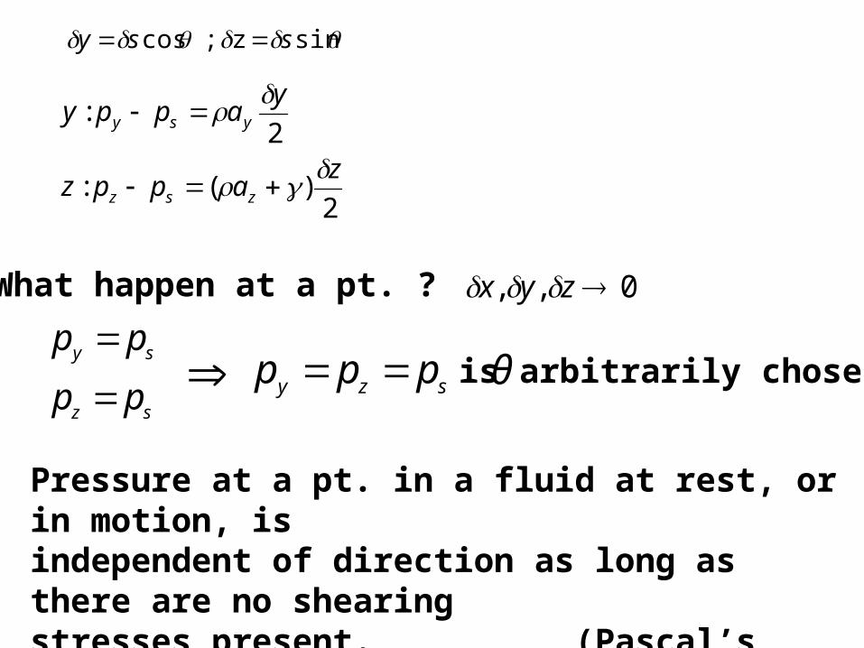
What happen at a pt. ? 0 , , zyx
sz
sy
pp
pp
szy ppp θ is arbitrarily chosen
Pressure at a pt. in a fluid at rest, or in motion, isindependent of direction as long as there are no shearingstresses present. (Pascal’s law)
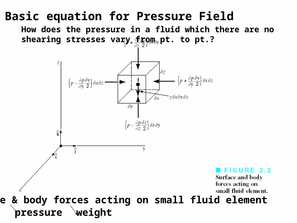
2.2 Basic equation for Pressure Field
Surface & body forces acting on small fluid elementpressure weight
How does the pressure in a fluid which there are no shearing stresses vary from pt. to pt.?
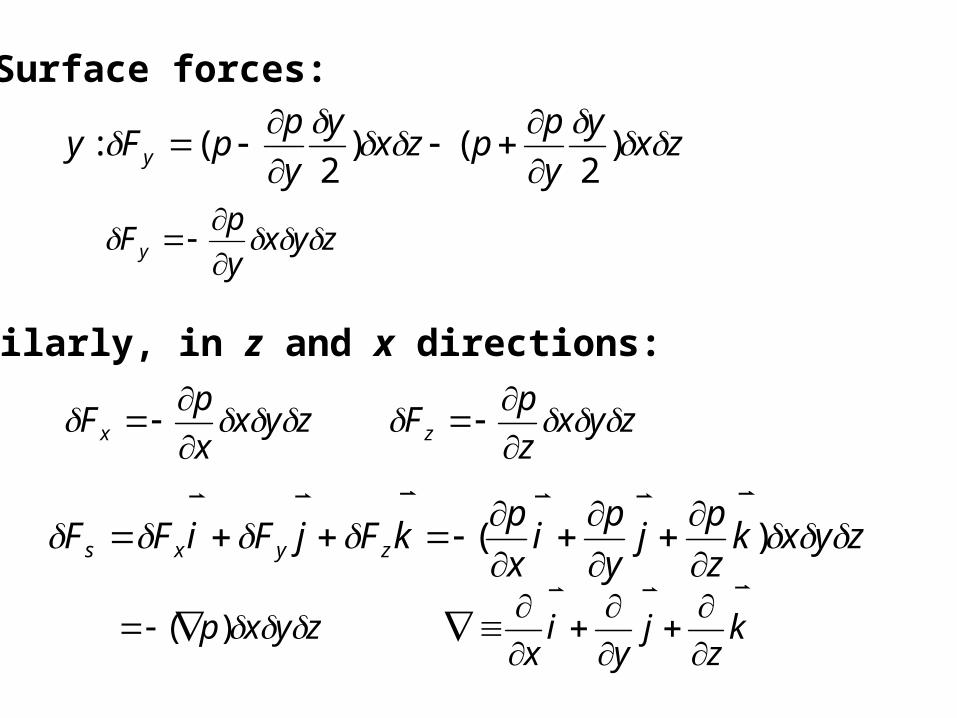
Surface forces:
zxy
y
ppzx
y
y
ppFy y )
2()
2(:
zyxy
pFy
Similarly, in z and x directions:
zyxx
pFx
zyxz
pFz
zyxkz
pj
y
pi
x
pkFjFiFF zyxs )(
kz
jy
ix
zyxp
)(

Newton’s second law
zyxzyxpWFamF s
azyx
2.3 Pressure variation in a fluid at rest
akp
General equation of motion for a fluid in which thereare no shearing stresses.
)2.4 Eq.(
0 0
dz
dpz
p
kpa
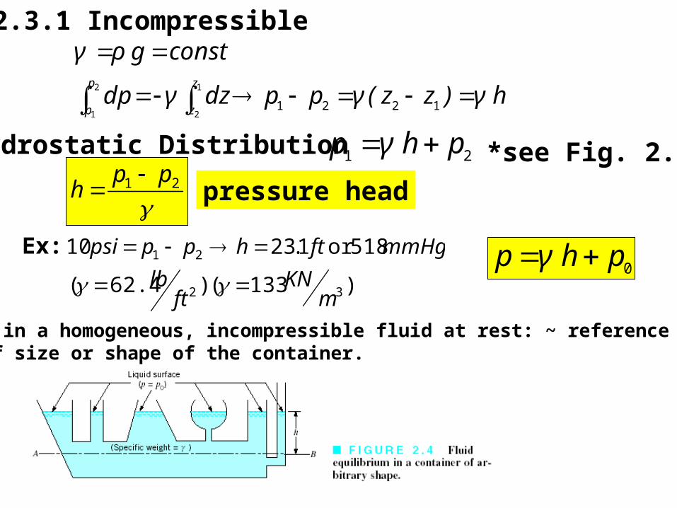
2.3.1 Incompressible
hγ)zz(γppdzγdp
constgργz
z
p
p
1221
1
2
2
1
Hydrostatic Distribution 21 phγp *see Fig. 2.2
21 pp
h
pressure head
Ex:
)133( )62.4(
518or 1.2310
32
21
mKN
ftlb
mmHgfthpppsi
0phγp
Pressure in a homogeneous, incompressible fluid at rest: ~ reference level,indep. of size or shape of the container.

The required equality of pressures at equal elevationsThroughout a system. )52 ( 1
1
22 ..FigF
A
AF
Transmission of fluid pressure
2.3.2 Compressible Fluid perfect gas: RTρp
2
1
2
1)z(z const. , ln 21
1
2pp
ZZ Rg
T
dz
R
g
p
p
p
dpRT
gpg
dz
dp
Assume
0
1212
210
)(exp
conditions isothermal ,
RT
zzgpp
zzoverTT
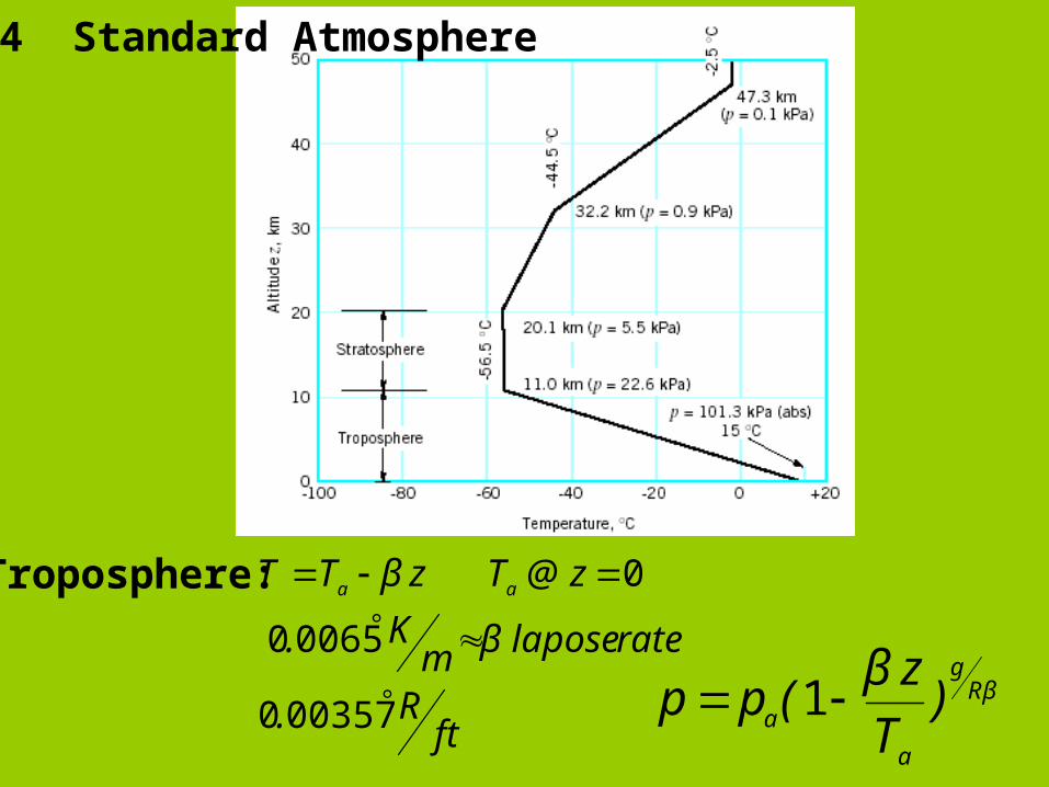
Troposphere:
003570
00650
0
ftR.
ratelaposeβmK.
z@TzβTT aa
βRg
a
a )T
zβ(pp 1
2.4 Standard Atmosphere

vaporatm phγp (Mercury barometer)Example 2.3 )pascal(
m
Npa
2
2.6 Manometry 1. Piezometer Tube: 2. U-Tube Manometer: 3. Inclined-tube manometer
gasa not liquid, 3. reasonable is h 2. 1 1 不大aa pppp.
1122 hγhγpA
see examples
*explain Fig. 2.11 Differential U-tube manometer
113322 hγhγhγpp BA Example 2.5
2.5 Measurement of Pressure See Fig. 2.7 Absolute & Gage pressure
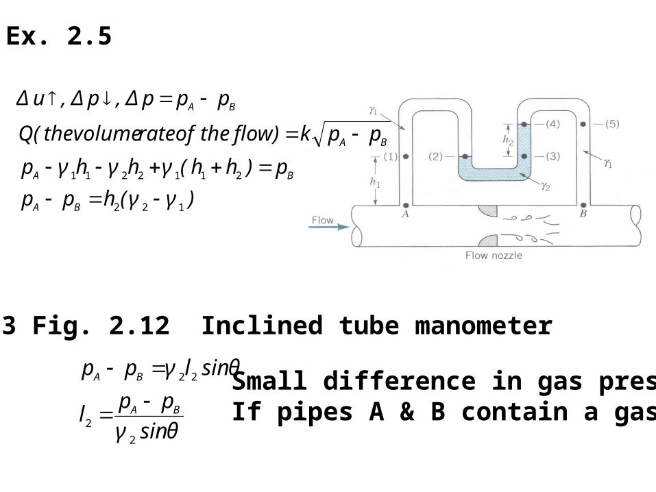
Ex. 2.5
)γγ(hpp
p)hh(γhγhγp
ppk)flowtheofratevolumethe(Q
pppΔ,pΔ,uΔ
BA
BA
BA
BA
122
2112211
2.6.3 Fig. 2.12 Inclined tube manometer
θsinγ
ppl
θsinlγpp
BA
BA
2
2
22
Small difference in gas pressureIf pipes A & B contain a gas

2.7 Mechanical and Electronic Pressure Measuring Device
. Bourdon pressure gage (elastic structure) Bourdon Tube ,p curved tube straight
deformation dial
. A zero reading on the gage indicates that the measured pressure
. Pressure transducer- pressure V.S. time Bourdon tube is connected to a linear variable differential transformer(LVDT), Fig. 2.14 coil; voltage
. Aneroid barometer-measure atmospheric pressure (absolute pressure)

This voltage is linear function of the pressure, and couldbe recorded on an oscillograph, or digitized for storageor processing on computer.
Disadvantage-elastic sensing element meas. pressure are static or only changing slowly(quasistatic). relatively mass of Bourdon tube
<diaphragm>
*strain-gage pressure transducer * Fig. 2.15 (arterial blood pressure) piezo-electric crystal. (Refs. 3, 4, 5 )
1Hz
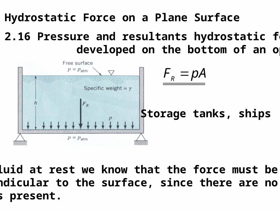
2.8 Hydrostatic Force on a Plane Surface
pAFR
Storage tanks, ships
Fig. 2.16 Pressure and resultants hydrostatic force developed on the bottom of an open tank.
. For fluid at rest we know that the force must be perpendicular to the surface, since there are no shearing stress present.

. Pressure varies linearly with depth if incompressibleg
dz
dp hp for open tank, Fig. 2.16
The resultant force acts through the centroid of the area
* Exercise 1.66dARd i
torque shearing stress
lRdlR
dlRd
ldRdA
ii
i
i
2
)(
20
2
2
Assume velocity distribution in the gap is lineari
i
RR
wR
0
i
i
RR
wlR
0
32
Ri
R0
θd
τ

hdAdF
constants. are , if
sin
A AR dAyhdAF
AR ydAF sin
first moment of the area∫A cAy=ydA
AhAyF cCR sin Indep. Of
The moment of the resultant force must equal the moment of theDistributed pressure force
AARR dAyydFyF 2sin
Ay
dAyyAF
c
ARCR
2
sin
Ax dAyI inertia) of(moment area theofmoment second2
2 ; cxcxc
xR AyII
Ay
Iy
2.18 Fig. seeect ,
xycxcccA
xycR
cRccA
xcR
IIxy
Ix
yyyy
Iy
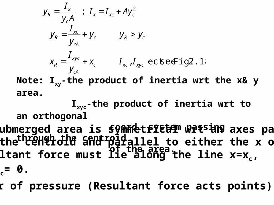
Note: Ixy-the product of inertia wrt the x& y area. Ixyc-the product of inertia wrt to an orthogonal coord. system passing through the centroid of the area.
If the submerged area is symmetrical wrt an axes passingthrough the centroid and parallel to either the x or y axes,the resultant force must lie along the line x=xc, since Ixyc= 0.
Center of pressure (Resultant force acts points)
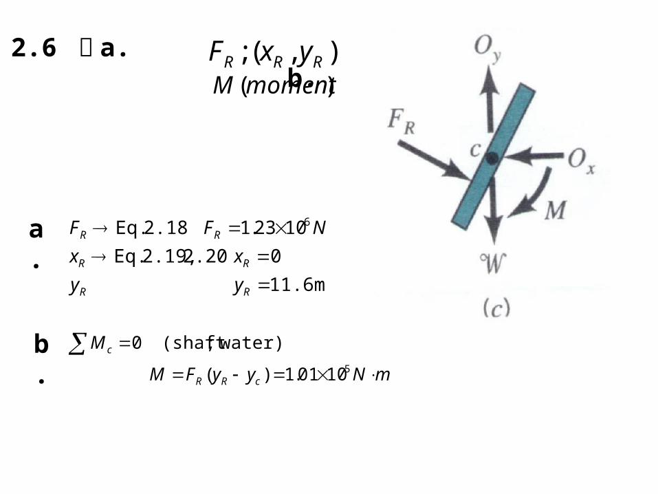
Example 2.6 求 a. b.
),( ; RRR yxF)(momentM
a.
11.6m
0 2.20 2.19, Eq.
1023.1 2.18 Eq. 6
RR
RR
RR
yy
xx
NFF
b. mNyyFM
M
cRR
c
51001.1)(
water);(shaft 0

2.9 Pressure Prism the pressure varies linearly with depth. See Fig. 2.19
Ah
bhh
e prismof pressurvolumeF
Ah
APF
R
AveR
2))((
2
1
)2
(
No matter what the shape of the pressure prism is, the resultantforce is still equal in magnitude to the volume of the pressure Prism, and it passes through the centroid of the volume.
First, draw the pressure prism out. dz
dp
0pzp
my
mFmFyF
KNFFF
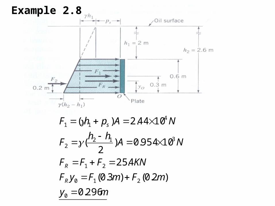
NAhh
F
NAphF
R
R
s
296.0
)2.0()3.0(
4.25
10954.0)2
(
1044.2)(
0
210
21
3122
411
Example 2.8
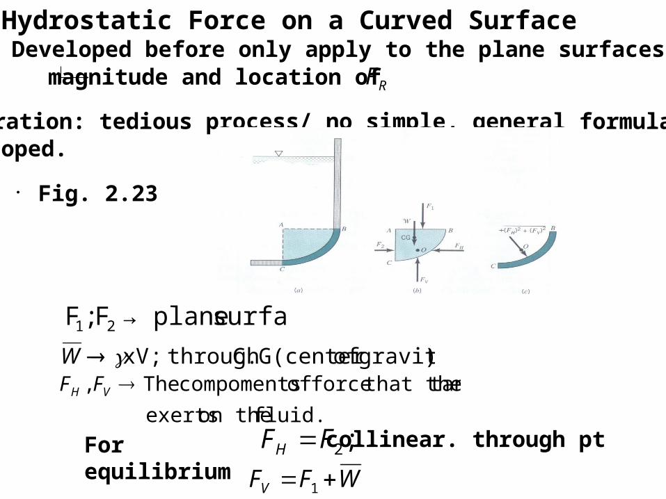
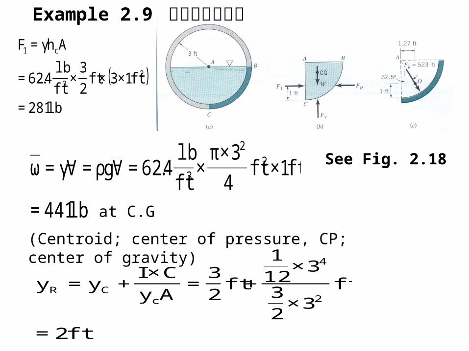
2.10 Hydrostatic Force on a Curved Surface. Eqs. Developed before only apply to the plane surfaces
magnitude and location of RF
. Integration: tedious process/ no simple, general formulas can be developed.
. Fig. 2.23
surface plane→F ;F 21
)gravity of C.G(center through ;xVW
fluid. on the exerts
tank that theforce of compoments The , VH FF
For equilibrium,
;2FFH WFFV 1
collinear. through pt
( )
lb281=
ft1×3×ft2
3×
ft
lb4.62=
Ahγ=F
23
c1
lb441=
ft1×ft4
3×π×
ft
lb4.62=∀gρ=∀γ=ω 2
2
3
at C.G
(Centroid; center of pressure, CP; center of gravity)
ft2=
ft3×
23
3×121
+ft2
3=
Ay
C×I+y=y
2
4
cCR
See Fig. 2.18
Example 2.9 排水管受力情形
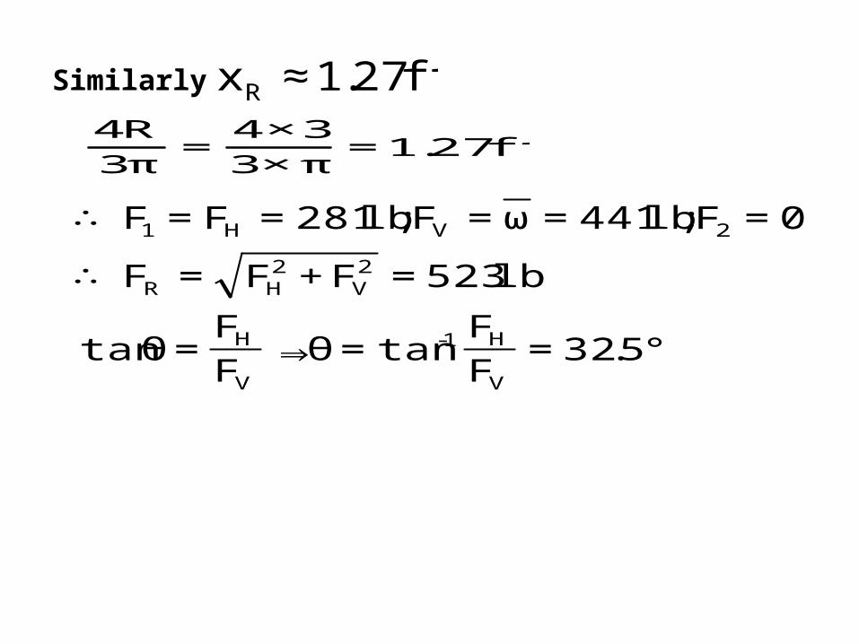
ft27.1≈xR
ft27.1=π×3
3×4=
π3
R4
°5.32=F
Ftan=θ⇒
F
F=θtan
lb523=F+F=F∴
0=F;lb441=ω=F;lb281=F=F∴
V
H1-
V
H
2V
2HR
2VH1
Similarly
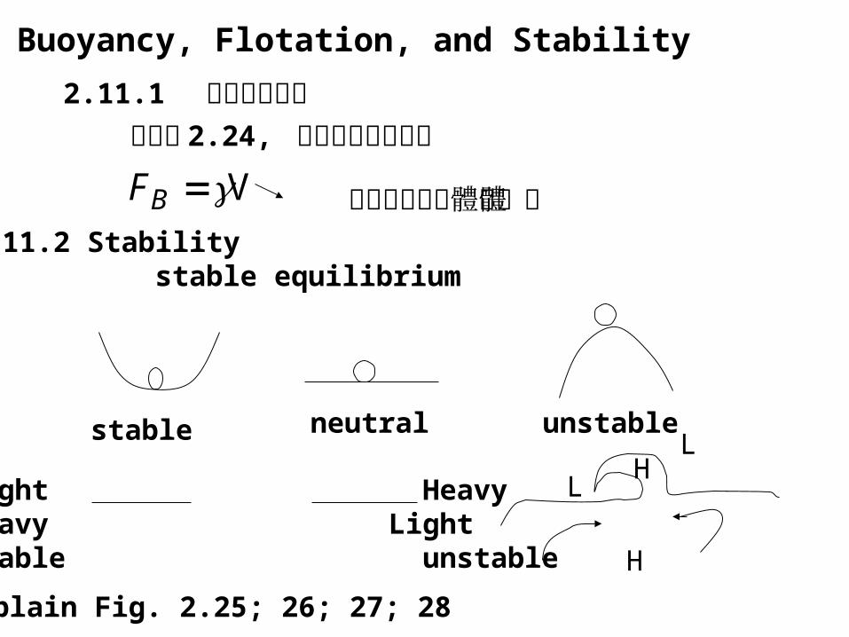
2.11 Buoyancy, Flotation, and Stability
2.11.1 阿基米德原理請看圖 2.24, 來分析其受力情形
VBF 任意形狀的物體之體積2.11.2 Stability stable equilibrium
stable neutral unstable
Light Heavy Heavy LightStable unstable
L
LH
H
Explain Fig. 2.25; 26; 27; 28