ch13 - g · 380 autocad and its applications—basics using the first point as displacement...
TRANSCRIPT
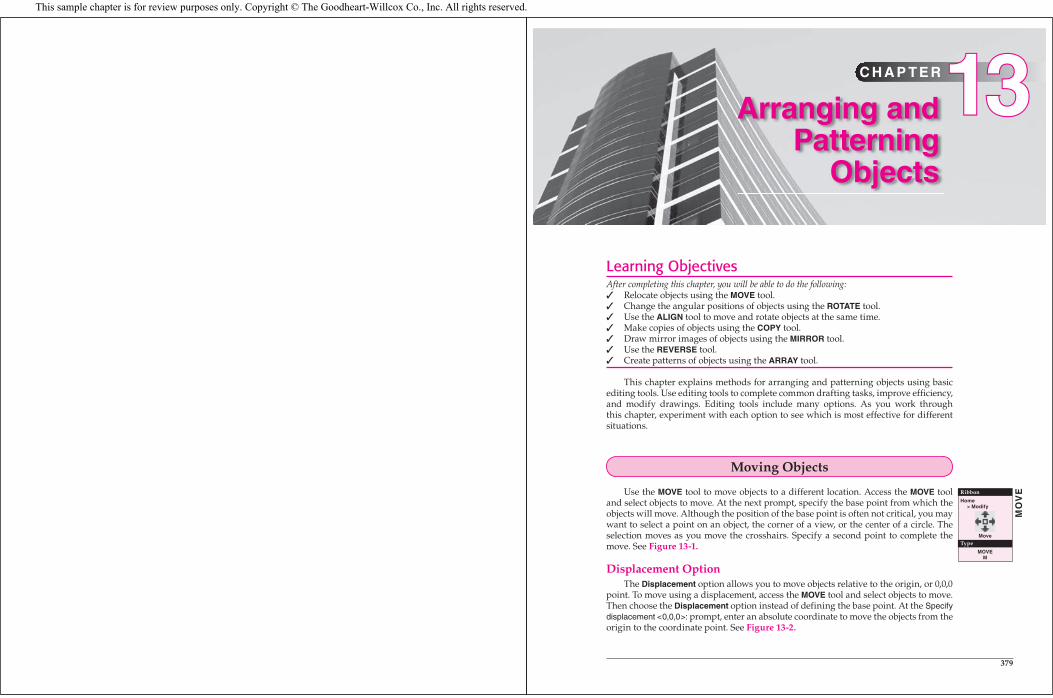
Learning ObjectivesAfter completing this chapter, you will be able to do the following:
Relocate objects using the MOVE tool.Change the angular positions of objects using the ROTATE tool.Use the ALIGN tool to move and rotate objects at the same time.Make copies of objects using the COPY tool.Draw mirror images of objects using the MIRROR tool.Use the REVERSE tool.Create patterns of objects using the ARRAY tool.
This chapter explains methods for arranging and patterning objects using basic editing tools. Use editing tools to complete common drafting tasks, improve efficiency, and modify drawings. Editing tools include many options. As you work through this chapter, experiment with each option to see which is most effective for different situations.
Moving Objects
Use the MOVE tool to move objects to a different location. Access the MOVE tool and select objects to move. At the next prompt, specify the base point from which the objects will move. Although the position of the base point is often not critical, you may want to select a point on an object, the corner of a view, or the center of a circle. The selection moves as you move the crosshairs. Specify a second point to complete the move. See Figure 13-1.
Displacement OptionThe Displacement option allows you to move objects relative to the origin, or 0,0,0
point. To move using a displacement, access the MOVE tool and select objects to move. Then choose the Displacement option instead of defining the base point. At the Specify displacement <0,0,0>: prompt, enter an absolute coordinate to move the objects from the origin to the coordinate point. See Figure 13-2.
�������
Arranging and Patterning
Objects
C H A P T E R1313
379
Ribbon
Home> Modify
Move
Type
MOVEM
MO
VE
This sample chapter is for review purposes only. Copyright © The Goodheart-Willcox Co., Inc. All rights reserved.

380 AutoCAD and Its Applications—Basics
Using the First Point As DisplacementAnother method for moving an object is to use the first point as the displacement.
The coordinates you use for the base point automatically define the coordinates for the direction and the distance for moving the object. Access the MOVE tool and select objects to move. Then specify the base point, and instead of locating the second point, right-click or press [Enter] or the space bar to accept the <use first point as displacement>default. See Figure 13-3.
PROFESSIONAL TIP
Use object snap modes while editing. For example, to move an object to the center of a circle, use the Center object snap mode to select the center of the circle.
Figure 13-1. Using the MOVE tool to relocate objects.
Select basepoint
Second point
Selected objectshighlighted
Drag objects intoposition and picksecond point
Figure 13-2. Using the Displacement option of the MOVE tool to move objects. In this example, the origin is the base point and the absolute coordinate point 2,2is the displacement.
Selected objectshighlighted
2,2
0,0
Chapter 13 Arranging and Patterning Objects 381
Exercise 13-1Access the Student Web site (www.g-wlearning.com/CAD) and complete Exercise 13-1.
Rotating Objects
Use the ROTATE tool to rotate objects. For example, rotate furniture to adjust an interior design plan, or rotate the north arrow on a site plan. Access the ROTATE tool and select objects to rotate. Proceed to the next prompt and specify the base point, or axis of rotation, around which the objects rotate. Next, enter a value or pick a point to specify a rotation angle at the Specify rotation angle or [Copy/Reference] <current>: prompt. See Figure 13-4.
Reference OptionThe Reference option is an alternative to entering a rotation angle, and allows you
to specify a new angle in relation to an existing angle. For example, use the Referenceoption to rotate a north arrow from 150° to 90°. Choose the Reference option and specify the current angle, 150° in the example, at the Specify reference angle: prompt. Next, specify the angle the objects should be, 90° in the example. See Figure 13-5A.
PROFESSIONAL TIP
Specify the reference and new angles using specifi c values; or choose points, often on existing objects, as shown in Figure 13-5B. Picking points is especially effective when you do not know the exact refer-ence and new angles.
Figure 13-3. Moving a circle using the selected base point, 1,1 in this example, as the displacement.
Object moves accordingto the coordinatesof the base point
Selected base pointat center 1,1
Selected objectshighlighted
2,2
X=1
Y=1
Ribbon
Home> Modify
Rotate
Type
ROTATERO
RO
TA
TE
382 AutoCAD and Its Applications—Basics
3030°°30°
–30° Rotation 30° RotationBase point(midpoint)
–30–30°°–30°
Rotated to 90°
Rotated to 90°
Original 150° Rotation
Original Unknown Rotation
1. Select the basepoint (midpoint)
1. Select the basepoint (midpoint)
150° 90°
Unknownangle
90°
2. Specify the currentrotation angle
3. Specify the newrotation angle
2. Pick two pointsto specify therotation angle
3. Specify the newrotation angle
A
B
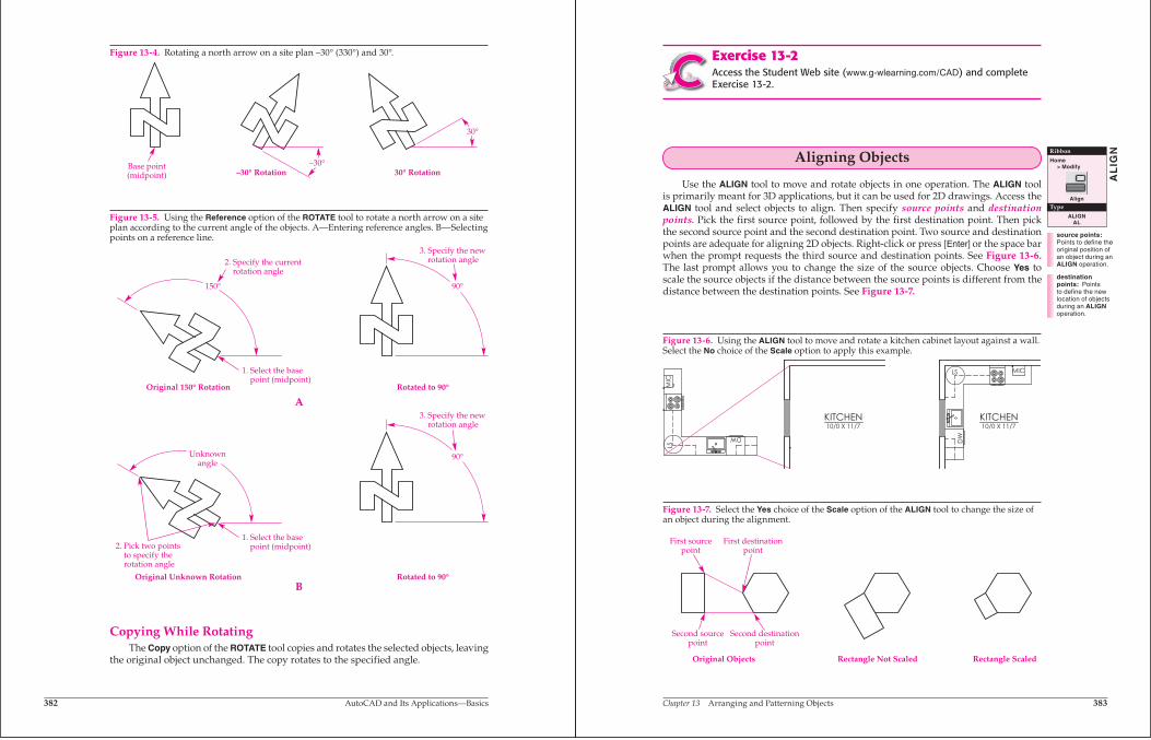
Figure 13-4. Rotating a north arrow on a site plan –30° (330°) and 30°.
Figure 13-5. Using the Reference option of the ROTATE tool to rotate a north arrow on a site plan according to the current angle of the objects. A—Entering reference angles. B—Selecting points on a reference line.
Copying While RotatingThe Copy option of the ROTATE tool copies and rotates the selected objects, leaving
the original object unchanged. The copy rotates to the specified angle.
Chapter 13 Arranging and Patterning Objects 383
Exercise 13-2Access the Student Web site (www.g-wlearning.com/CAD) and complete Exercise 13-2.
Aligning Objects
Use the ALIGN tool to move and rotate objects in one operation. The ALIGN tool is primarily meant for 3D applications, but it can be used for 2D drawings. Access the ALIGN tool and select objects to align. Then specify source points and destination points. Pick the first source point, followed by the first destination point. Then pick the second source point and the second destination point. Two source and destination points are adequate for aligning 2D objects. Right-click or press [Enter] or the space bar when the prompt requests the third source and destination points. See Figure 13-6.The last prompt allows you to change the size of the source objects. Choose Yes to scale the source objects if the distance between the source points is different from the distance between the destination points. See Figure 13-7.
source points: Points to define the original position of an object during an ALIGN operation.
destination points: Points to define the new location of objects during an ALIGNoperation.
Ribbon
Home> Modify
Align
Type
ALIGNAL
AL
IGN
DW
LS MIC
KITCHEN10/0 X 11/7
DW
LSM
IC
KITCHEN10/0 X 11/7
First sourcepoint
First destinationpoint
Second sourcepoint
Second destinationpoint
Original Objects Rectangle Not Scaled Rectangle Scaled
Figure 13-6. Using the ALIGN tool to move and rotate a kitchen cabinet layout against a wall. Select the No choice of the Scale option to apply this example.
Figure 13-7. Select the Yes choice of the Scale option of the ALIGN tool to change the size of an object during the alignment.
Ands jspois a thspo cnb angoxu igcuostues tre poiust piod agousgas on few ousi zougosa eossougsgo.
384 AutoCAD and Its Applications—Basics
Exercise 13-3Access the Student Web site (www.g-wlearning.com/CAD) and complete Exercise 13-3.
Copying Objects
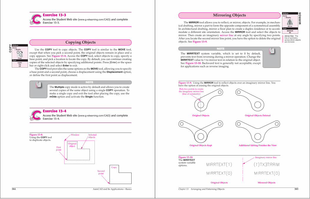
Use the COPY tool to copy objects. The COPY tool is similar to the MOVE tool, except that when you pick a second point, the original objects remain in place and a copy appears. See Figure 13-8. Access the COPY tool, select objects to copy, specify a base point, and pick a location to locate the copy. By default, you can continue creating copies of the selected objects by specifying additional points. Press [Enter] or the space bar or right-click and select Enter to exit.
The COPY tool provides the same options as the MOVE tool, allowing you to specify a base point and a second point, choose a displacement using the Displacement option, or define the first point as displacement.
NOTE
The Multiple copy mode is active by default and allows you to create several copies of the same object using a single COPY operation. To make a single copy and exit the tool after placing the copy, use the mOde option and activate the Single function.
Exercise 13-4Access the Student Web site (www.g-wlearning.com/CAD) and complete Exercise 13-4.
Ribbon
Home> Modify
Copy
Type
COPYCOCP
CO
PY
Window Selectedobjects
Firstpoint
Copy
Originalobject
Secondpoint
Figure 13-8.Using the COPY tool to duplicate objects.
Ands jspois a thspo cnb angoxu igcuostues tre poiust piod agousgas on few ousi zougosa eossougsgo.
Chapter 13 Arranging and Patterning Objects 385
Mirroring Objects
The MIRROR tool allows you to reflect, or mirror, objects. For example, in mechan-ical drafting, mirror a part to form the opposite component of a symmetrical assembly. In architectural drafting, mirror a floor plan to create a duplex residence or to accom-modate a different site orientation. Access the MIRROR tool and select the objects to mirror. Then create an imaginary mirror line at any angle by specifying two points. After you locate the second mirror line point, you have the option to delete the original objects. See Figure 13-9.
NOTE
The MIRRTEXT system variable, which is set to 0 by default,prevents text from reversing during a mirror operation. Change the MIRRTEXT value to 1 to mirror text in relation to the original object. See Figure 13-10. Backward text is generally not acceptable, except for applications such as reverse imaging.
Ribbon
Home> Modify
Mirror
Type
MIRRORMI
MIR
RO
R
mirror line: The line of symmetry across which objects are mirrored.
Original Objects Kept Additional Editing Finishes the View
Original Objects Original Objects Deleted
Pick two points to createthe imaginary mirror line
(line of symmetry)
Original Objects Mirrored Objects
Imaginary mirror line
Figure 13-9. Using the MIRROR tool to reflect objects over an imaginary mirror line. You have the option of erasing the original objects.
Figure 13-10.The MIRRTEXTsystem variable options.
386 AutoCAD and Its Applications—Basics
Exercise 13-5Access the Student Web site (www.g-wlearning.com/CAD) and complete Exercise 13-5.
Reversing an Object’s Point Calculation
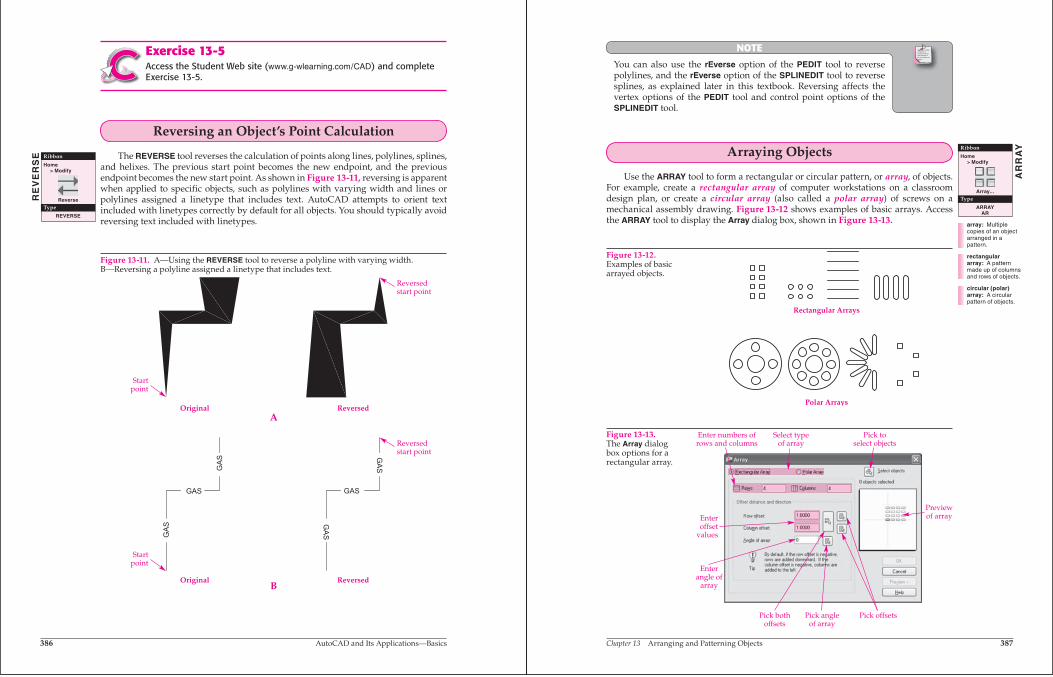
The REVERSE tool reverses the calculation of points along lines, polylines, splines, and helixes. The previous start point becomes the new endpoint, and the previous endpoint becomes the new start point. As shown in Figure 13-11, reversing is apparent when applied to specific objects, such as polylines with varying width and lines or polylines assigned a linetype that includes text. AutoCAD attempts to orient text included with linetypes correctly by default for all objects. You should typically avoid reversing text included with linetypes.
Ribbon
Home> Modify
Reverse
Type
REVERSE
RE
VE
RS
E
GAS
GAS
GAS G
AS
GAS
GAS
Startpoint
Startpoint
Reversedstart point
Reversedstart point
OriginalA
B
Reversed
Original Reversed
Figure 13-11. A—Using the REVERSE tool to reverse a polyline with varying width. B—Reversing a polyline assigned a linetype that includes text.
Ands jspois a thspo cnb angoxu igcuostues tre poiust piod agousgas on few ousi zougosa eossougsgo.
Chapter 13 Arranging and Patterning Objects 387
NOTE
You can also use the rEverse option of the PEDIT tool to reverse polylines, and the rEverse option of the SPLINEDIT tool to reverse splines, as explained later in this textbook. Reversing affects the vertex options of the PEDIT tool and control point options of the SPLINEDIT tool.
Arraying Objects
Use the ARRAY tool to form a rectangular or circular pattern, or array, of objects. For example, create a rectangular array of computer workstations on a classroom design plan, or create a circular array (also called a polar array) of screws on a mechanical assembly drawing. Figure 13-12 shows examples of basic arrays. Access the ARRAY tool to display the Array dialog box, shown in Figure 13-13.
Ribbon
Home> Modify
Array...
Type
ARRAYAR
AR
RA
Y
Rectangular Arrays
Polar Arrays
Enteroffset
values
Enterangle of
array
Pick bothoffsets
Pick angleof array
Pick offsets
Previewof array
Pick toselect objects
Select typeof array
Enter numbers ofrows and columns
Figure 13-12.Examples of basic arrayed objects.
Figure 13-13.The Array dialog box options for a rectangular array.
array: Multiple copies of an object arranged in a pattern.
rectangular array: A pattern made up of columns and rows of objects.
circular (polar) array: A circular pattern of objects.
388 AutoCAD and Its Applications—Basics
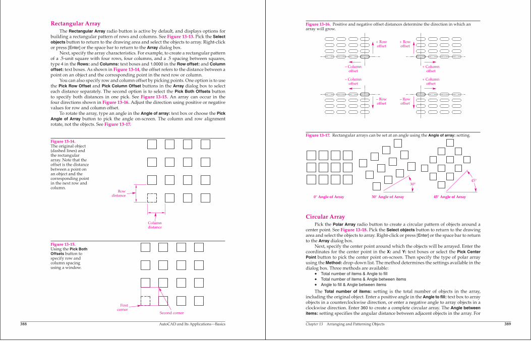
Rectangular ArrayThe Rectangular Array radio button is active by default, and displays options for
building a rectangular pattern of rows and columns. See Figure 13-13. Pick the Select objects button to return to the drawing area and select the objects to array. Right-click or press [Enter] or the space bar to return to the Array dialog box.
Next, specify the array characteristics. For example, to create a rectangular pattern of a .5-unit square with four rows, four columns, and a .5 spacing between squares, type 4 in the Rows: and Columns: text boxes and 1.0000 in the Row offset: and Column offset: text boxes. As shown in Figure 13-14, the offset refers to the distance between a point on an object and the corresponding point in the next row or column.
You can also specify row and column offset by picking points. One option is to use the Pick Row Offset and Pick Column Offset buttons in the Array dialog box to select each distance separately. The second option is to select the Pick Both Offsets button to specify both distances in one pick. See Figure 13-15. An array can occur in the four directions shown in Figure 13-16. Adjust the direction using positive or negative values for row and column offset.
To rotate the array, type an angle in the Angle of array: text box or choose the Pick Angle of Array button to pick the angle on-screen. The column and row alignment rotate, not the objects. See Figure 13-17.
Rowdistance
Columndistance
Firstcorner
Second corner
Figure 13-14.The original object (dashed lines) and the rectangular array. Note that the offset is the distance between a point on an object and the corresponding point in the next row and column.
Figure 13-15.Using the Pick Both Offsets button to specify row and column spacing using a window.
Chapter 13 Arranging and Patterning Objects 389
Circular ArrayPick the Polar Array radio button to create a circular pattern of objects around a
center point. See Figure 13-18. Pick the Select objects button to return to the drawing area and select the objects to array. Right-click or press [Enter] or the space bar to return to the Array dialog box.
Next, specify the center point around which the objects will be arrayed. Enter the coordinates for the center point in the X: and Y: text boxes or select the Pick Center Point button to pick the center point on-screen. Then specify the type of polar array using the Method: drop-down list. The method determines the settings available in the dialog box. Three methods are available:
• Total number of items & Angle to fill• Total number of items & Angle between items• Angle to fill & Angle between items
The Total number of items: setting is the total number of objects in the array, including the original object. Enter a positive angle in the Angle to fill: text box to array objects in a counterclockwise direction, or enter a negative angle to array objects in a clockwise direction. Enter 360 to create a complete circular array. The Angle between items: setting specifies the angular distance between adjacent objects in the array. For
+ Rowoffset
+ Rowoffset
– Rowoffset
– Rowoffset
– Columnoffset
– Columnoffset
+ Columnoffset
+ Columnoffset
Figure 13-16. Positive and negative offset distances determine the direction in which an array will grow.
30°45°
0° Angle of Array 30° Angle of Array 45° Angle of Array
Figure 13-17. Rectangular arrays can be set at an angle using the Angle of array: setting.

390 AutoCAD and Its Applications—Basics
Figure 13-20.Default base points for objects.
example, to create a circular pattern of five items spaced 18° apart, enter 5 in the Total number of items: text box and 18 in the Angle between items: text box.
You can set objects to rotate as they are arrayed by checking Rotate items as copied.This keeps the same face of each object pointing toward the center point. If you do not rotate objects as they are arrayed, they remain in the same orientation as the original object. See Figure 13-19.
When you create a polar array, the base point of the object rotates and remains at a constant distance from the center point. The default base point varies for different types of objects, as shown in Figure 13-20. If the default base point does not produce the desired array, choose a different base point for the selected object. Pick the More button to display the Object base point area. Deactivate the Set to object’s default check box. Enter a new base point in the text boxes or pick the button to select a base point on-screen.
Enter center pointcoordinates orpick button to
select on screen
Select method
Enter values forselected method
Check to rotateobjects in array
Pick to set basepoint of objects
Previewimage
Pick to selectobjects to bearrayed
Figure 13-18. The Array dialog box options for a polar array.
A B
Object Type Default Base Point
Arc, circle, ellipseRectangle, polygonLine, polyline, donutBlock, text
CenterFirst cornerStart pointInsertion point
Figure 13-19.Rotating objects in a polar array. A—CheckRotate items as copied to rotate the square during the array. B—Uncheck Rotate items as copied to maintain the original orientation of objects during the array.
Ands jspois a thspo cnb angoxu igcuostues tre poiust piod agousgas on few ousi zougosa eossougsgo.
Chapter 13 Arranging and Patterning Objects 391
NOTE
Use the Angle to fi ll & Angle between items method if you do not know the number of items to array.
Exercise 13-6Access the Student Web site (www.g-wlearning.com/CAD) and complete Exercise 13-6.
Chapter TestAnswer the following questions. Write your answers on a separate sheet of paper or go to the Student Web site (www.g-wlearning.com/CAD) and complete the elec-tronic chapter test.
1. List two locations drafters normally choose as the base point when using the MOVE tool.
2. How would you rotate an object 45° clockwise? 3. Briefly describe the two methods of using the Reference option of the ROTATE
tool. 4. Name the tool that you can use to move and rotate an object at the same time. 5. How many points must you select to align an object in a 2D drawing? 6. Which ribbon tab and panel contains the MOVE and COPY tools? 7. Explain the difference between the MOVE and COPY tools. 8. Briefly explain how to make several copies of the same object. 9. Which tool allows you to draw a reflected image of an existing object? 10. What is the purpose of the REVERSE tool? 11. What is the difference between polar and rectangular arrays? 12. What four values should you know before you create a rectangular array? 13. Suppose an object is 1.5″ (38 mm) wide and you want to create a rectangular
array with .75″ (19 mm) spacing between objects. What should you specify for the distance between columns?
14. How do you specify a clockwise circular array rotation? 15. What values should you know before you create a circular array?
392 AutoCAD and Its Applications—Basics
Dra
win
g P
rob
lem
s -
Chap
ter
13Drawing ProblemsStart AutoCAD if it is not already started. Start a new drawing for each problem using an appropriate template of your choice. The template should include layers, text styles, and table styles, when necessary, for drawing the given objects. Add layers, text styles, and table styles as needed. Draw all objects using appropriate layers, text styles, table styles, justification, and format. Follow the specific instructions for each problem. Use only drawing and editing tools and techniques you have already learned. Do not draw dimensions. Use your own judgment and approximate dimensions when necessary.
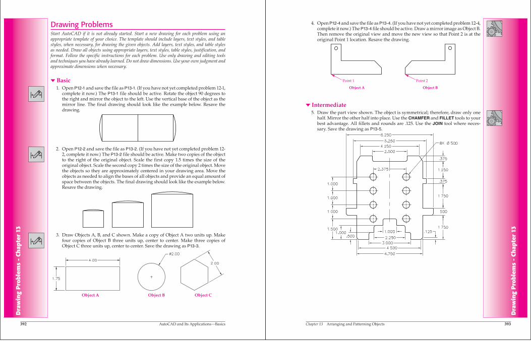
� Basic 1. Open P12-1 and save the file as P13-1. (If you have not yet completed problem 12-1,
complete it now.) The P13-1 file should be active. Rotate the object 90 degrees to the right and mirror the object to the left. Use the vertical base of the object as the mirror line. The final drawing should look like the example below. Resave the drawing.
2. Open P12-2 and save the file as P13-2. (If you have not yet completed problem 12-2, complete it now.) The P13-2 file should be active. Make two copies of the object to the right of the original object. Scale the first copy 1.5 times the size of the original object. Scale the second copy 2 times the size of the original object. Move the objects so they are approximately centered in your drawing area. Move the objects as needed to align the bases of all objects and provide an equal amount of space between the objects. The final drawing should look like the example below. Resave the drawing.
Object A Object B Object C
3. Draw Objects A, B, and C shown. Make a copy of Object A two units up. Make four copies of Object B three units up, center to center. Make three copies of Object C three units up, center to center. Save the drawing as P13-3.
Chapter 13 Arranging and Patterning Objects 393
Dra
win
g P
rob
lem
s -
Chap
ter
13
4. Open P12-4 and save the file as P13-4. (If you have not yet completed problem 12-4, complete it now.) The P13-4 file should be active. Draw a mirror image as Object B. Then remove the original view and move the new view so that Point 2 is at the original Point 1 location. Resave the drawing.
� Intermediate 5. Draw the part view shown. The object is symmetrical; therefore, draw only one
half. Mirror the other half into place. Use the CHAMFER and FILLET tools to your best advantage. All fillets and rounds are .125. Use the JOIN tool where neces-sary. Save the drawing as P13-5.
Object A Object B
Point 1 Point 2

394 AutoCAD and Its Applications—Basics
Dra
win
g P
rob
lem
s -
Chap
ter
13 6. Draw the portion of the part view shown. Mirror the right half into place. Use the
CHAMFER and FILLET tools to your best advantage. Save the drawing as P13-6.
7. Draw the electronic schematic symbols shown. Mirror the drawing, but make sure the text remains readable. Delete the original image during the mirroring process. Save the drawing as P13-7.
Dra
win
g P
rob
lem
s -
Chap
ter
13
Chapter 13 Arranging and Patterning Objects 395
Dra
win
g P
rob
lem
s -
Chap
ter
13
8. Draw the timer schematic shown. Save the drawing as P13-8.
A
D
C C C C C
C C C C C
D D D
B B B B B
D D D D
A A A A
A A A A A
9. Use tracking and object snaps to draw the board shown, based on the following instructions:A. Draw the outline first, followed by the ten ∅.500 holes (A).B. The holes labeled B are located vertically halfway between the centers of
the holes labeled A. They have a diameter one-quarter the size of the holes labeled A.
C. The holes labeled C are located vertically halfway between the holes labeled A and B. Their diameter is three-quarters of the diameter of the holes labeled B.
D. The holes labeled D are located horizontally halfway between the centers of the holes labeled A. These holes have the same diameter as the holes labeled B.
E. Draw the rectangles around the circles as shown.F. Do not draw dimensions, notes, or labels.G. Save the drawing as P13-9.
Dra
win
g P
rob
lem
s -
Chap
ter
13

396 AutoCAD and Its Applications—Basics
Dra
win
g P
rob
lem
s -
Chap
ter
13 10. Draw the portion of the gasket shown on the left. Use the MIRROR tool to complete
the gasket as shown on the right. Save the drawing as P13-10.
11. Draw the padded bench shown. Use the COPY and ARRAY tools as needed. Save the drawing as P13-11.
Chapter 13 Arranging and Patterning Objects 397
Dra
win
g P
rob
lem
s -
Chap
ter
13
12. Draw the hand wheel shown. Use the ARRAY tool to draw the spokes. Save the drawing as P13-12.
� Advanced 13. Use the engineer’s sketch and notes shown to draw the sprocket. Create a front
and side view of the sprocket. Use the ARRAY tool as needed. Save the drawing as P13-13.

398 AutoCAD and Its Applications—Basics
Dra
win
g P
rob
lem
s -
Chap
ter
13 14. Draw the views of the sprocket shown. Use ARRAY to construct the hole and
tooth arrangements. Save the drawing as P13-14.
15. Draw the refrigeration system schematic shown. Save the drawing as P13-15.
Chapter 13 Arranging and Patterning Objects 399
Dra
win
g P
rob
lem
s -
Chap
ter
13
16. The structural sketch shown is a steel column arrangement on a concrete floor slab for a new building. The I-shaped symbols represent the steel columns. The columns are arranged in “bay lines” and “column lines.” The column lines are numbered 1, 2, and 3. The bay lines are labeled A through G. The width of a bay is 24′-0″. Line balloons, or tags, identify the bay and column lines. Draw the arrangement, using ARRAY for the steel column symbols and the tags. The following guidelines will help:A. Begin a new drawing using an architectural template.B. Select architectural units and set up the drawing to print on a 36 × 24 sheet
size. Determine the scale required for the floor plan to fit on this sheet size and specify the drawing limits accordingly.
C. Draw the steel column symbol to the dimensions given.D. Set the grid spacing at 2′-0″ (24″).E. Set the snap spacing at 12″.F. Draw all other objects.G. Place text inside the balloon tags. Set the running object snap mode to Center
and justify the text to Middle. Make the text height 6″.H. Save the drawing as P13-16.
400 AutoCAD and Its Applications—Basics
Dra
win
g P
rob
lem
s -
Chap
ter
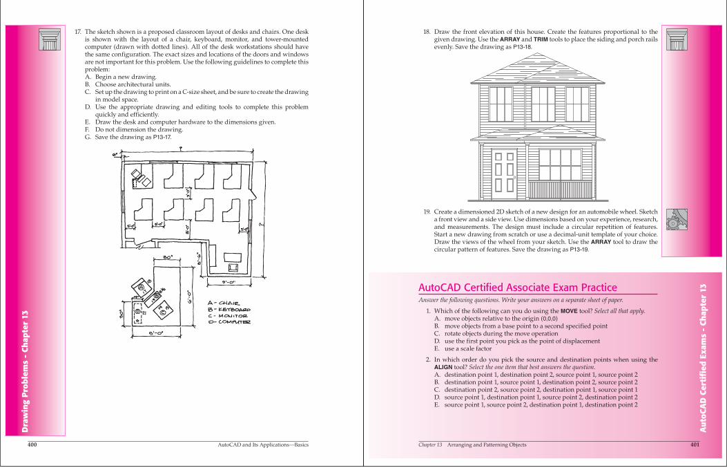
13 17. The sketch shown is a proposed classroom layout of desks and chairs. One desk
is shown with the layout of a chair, keyboard, monitor, and tower-mounted computer (drawn with dotted lines). All of the desk workstations should have the same configuration. The exact sizes and locations of the doors and windows are not important for this problem. Use the following guidelines to complete this problem:A. Begin a new drawing.B. Choose architectural units.C. Set up the drawing to print on a C-size sheet, and be sure to create the drawing
in model space.D. Use the appropriate drawing and editing tools to complete this problem
quickly and efficiently.E. Draw the desk and computer hardware to the dimensions given.F. Do not dimension the drawing.G. Save the drawing as P13-17.
Chapter 13 Arranging and Patterning Objects 401
Au
toC
AD
Cer
tifi
ed E
xam
s -
Chap
ter
13
18. Draw the front elevation of this house. Create the features proportional to the given drawing. Use the ARRAY and TRIM tools to place the siding and porch rails evenly. Save the drawing as P13-18.
19. Create a dimensioned 2D sketch of a new design for an automobile wheel. Sketch a front view and a side view. Use dimensions based on your experience, research, and measurements. The design must include a circular repetition of features. Start a new drawing from scratch or use a decimal-unit template of your choice. Draw the views of the wheel from your sketch. Use the ARRAY tool to draw the circular pattern of features. Save the drawing as P13-19.
AutoCAD Certified Associate Exam PracticeAnswer the following questions. Write your answers on a separate sheet of paper.
1. Which of the following can you do using the MOVE tool? Select all that apply. A. move objects relative to the origin (0,0,0)B. move objects from a base point to a second specified pointC. rotate objects during the move operationD. use the first point you pick as the point of displacementE. use a scale factor
2. In which order do you pick the source and destination points when using the ALIGN tool? Select the one item that best answers the question. A. destination point 1, destination point 2, source point 1, source point 2B. destination point 1, source point 1, destination point 2, source point 2C. destination point 2, source point 2, destination point 1, source point 1 D. source point 1, destination point 1, source point 2, destination point 2E. source point 1, source point 2, destination point 1, destination point 2

402 AutoCAD and Its Applications—Basics
Au
toC
AD
Cer
tifi
ed E
xam
s -
Chap
ter
13 3. In the array shown below, what would you enter for the row and column offsets?
Select the one item that best answers the question.A. row offset 1.00, column offset 2.00B. row offset 2.00, column offset 1.00C. row offset 2.00, column offset 4.00D. row offset 4.00, column offset 2.00E. row offset 5.00, column offset 6.00F. row offset 6.00, column offset 5.00
Ø4.00
1.00
2.00
AutoCAD Certified Professional Exam PracticeFollow the instructions in each problem. Write your answers on a separate sheet of paper.
1. Navigate to this chapter on the Student Web site and open CPE-13array.dwg. Use the ARRAY tool to finish the view of a fan plate as shown. Analyze the
drawing and use the most appropriate options for the polar array. What are the coordinates of Point 1?
Point 1(midpoint)
2. Navigate to this chapter on the Student Web site and open CPE-13mirror.dwg. Create a mirror line starting at absolute coordinates 13′,8′ and extending 5′ at
120°. Mirror the couch across this line. What are the coordinates of Point 1?
Point 1