ch12 - bioretention 14july2009 quality/surface water protection... · bioretention 12-1 july 2007...
TRANSCRIPT
NCDENR Stormwater BMP Manual Chapter Revised 07-24-09
Bioretention 12-1 July 2007
12 Bioretention
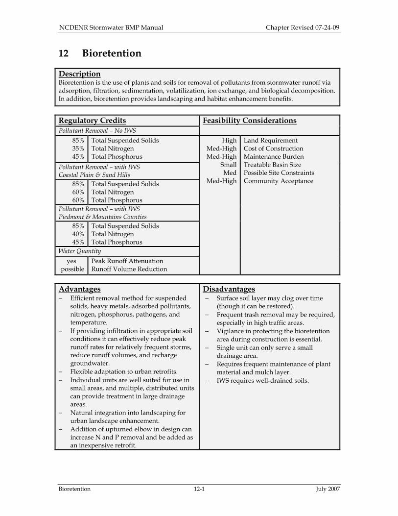
Description Bioretention is the use of plants and soils for removal of pollutants from stormwater runoff via adsorption, filtration, sedimentation, volatilization, ion exchange, and biological decomposition. In addition, bioretention provides landscaping and habitat enhancement benefits.
Regulatory Credits Feasibility Considerations Pollutant Removal – No IWS
85% 35% 45%
Total Suspended Solids Total Nitrogen Total Phosphorus
High Med-High Med-High
Small Med
Med-High
Land Requirement Cost of Construction Maintenance Burden Treatable Basin Size Possible Site Constraints Community Acceptance
Pollutant Removal – with IWS Coastal Plain & Sand Hills
85% 60% 60%
Total Suspended Solids Total Nitrogen Total Phosphorus
Pollutant Removal – with IWS Piedmont & Mountains Counties
85% 40% 45%
Total Suspended Solids Total Nitrogen Total Phosphorus
Water Quantity
yes possible
Peak Runoff Attenuation Runoff Volume Reduction
Advantages − Efficient removal method for suspended
solids, heavy metals, adsorbed pollutants, nitrogen, phosphorus, pathogens, and temperature.
− If providing infiltration in appropriate soil conditions it can effectively reduce peak runoff rates for relatively frequent storms, reduce runoff volumes, and recharge groundwater.
− Flexible adaptation to urban retrofits.
− Individual units are well suited for use in small areas, and multiple, distributed units can provide treatment in large drainage areas.
− Natural integration into landscaping for urban landscape enhancement.
− Addition of upturned elbow in design can increase N and P removal and be added as an inexpensive retrofit.
Disadvantages − Surface soil layer may clog over time
(though it can be restored).
− Frequent trash removal may be required, especially in high traffic areas.
− Vigilance in protecting the bioretention area during construction is essential.
− Single unit can only serve a small drainage area.
− Requires frequent maintenance of plant material and mulch layer.
− IWS requires well-drained soils.
NCDENR Stormwater BMP Manual Chapter Revised 07-24-09
Bioretention 12-2 July 2007
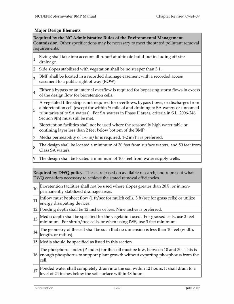
Major Design Elements
Required by the NC Administrative Rules of the Environmental Management Commission. Other specifications may be necessary to meet the stated pollutant removal requirements.
1 Sizing shall take into account all runoff at ultimate build-out including off-site drainage.
2 Side slopes stabilized with vegetation shall be no steeper than 3:1.
3 BMP shall be located in a recorded drainage easement with a recorded access easement to a public right of way (ROW).
4 Either a bypass or an internal overflow is required for bypassing storm flows in excess of the design flow for bioretention cells.
5
A vegetated filter strip is not required for overflows, bypass flows, or discharges from a bioretention cell (except for within ½ mile of and draining to SA waters or unnamed tributaries of to SA waters). For SA waters in Phase II areas, criteria in S.L. 2006-246 Section 9(h) must still be met.
6 Bioretention facilities shall not be used where the seasonally high water table or confining layer less than 2 feet below bottom of the BMP.
7 Media permeability of 1-6 in/hr is required, 1-2 in/hr is preferred.
8 The design shall be located a minimum of 30 feet from surface waters, and 50 feet from Class SA waters.
9 The design shall be located a minimum of 100 feet from water supply wells.
Required by DWQ policy. These are based on available research, and represent what DWQ considers necessary to achieve the stated removal efficiencies.
10 Bioretention facilities shall not be used where slopes greater than 20%, or in non-permanently stabilized drainage areas.
11 Inflow must be sheet flow (1 ft/sec for mulch cells, 3 ft/sec for grass cells) or utilize energy dissipating devices.
12 Ponding depth shall be 12 inches or less. Nine inches is preferred.
13 Media depth shall be specified for the vegetation used. For grassed cells, use 2 feet minimum. For shrub/tree cells, or when using IWS, use 3 feet minimum.
14 The geometry of the cell shall be such that no dimension is less than 10 feet (width, length, or radius).
15 Media should be specified as listed in this section.
16 The phosphorus index (P-index) for the soil must be low, between 10 and 30. This is enough phosphorus to support plant growth without exporting phosphorus from the cell.
17 Ponded water shall completely drain into the soil within 12 hours. It shall drain to a level of 24 inches below the soil surface within 48 hours.

NCDENR Stormwater BMP Manual Chapter Revised 07-24-09
Bioretention 12-3 July 2007
18
An underdrain shall typically be installed if in-situ soil drainage is less than 2 in/hr or if there is in situ loamy soil (~12% or more of fines). This is usually the case for soil tighter than sandy loam or if there has been significant soil compaction from construction.
19 Clean-out pipes must be provided if underdrains are required.
20 Grassed bioretention cells may be used, however, grassed cells must be sodded and the sod must not be grown in soil with an impermeable (clay) layer.
12.1. General Characteristics and Purpose A bioretention cell consists of a depression in the ground filled with a soil media mixture that supports various types of water-tolerant vegetation. The surface of the BMP is depressed in bioretention facilities to allow for ponding of runoff that filters through the BMP media. Water exits the bioretention area via exfiltration into the surrounding soil, flow out an underdrain, and evapotranspiration. The surface of the cell is protected from weeds, mechanical erosion, and desiccation by a layer of mulch. Bioretention is an efficient method for removing a wide variety of pollutants, such as suspended solids, heavy metals, nutrients, pathogens, and temperature (NC Cooperative Extension, 2006). Bioretention areas provide some nutrient uptake in addition to physical filtration. If located at a site with appropriate soil conditions to provide infiltration, bioretention can also be effective in reducing peak runoff rates, reducing runoff volumes, and recharging groundwater. Many development projects present a challenge to the designer of conventional stormwater BMPs because of physical site constraints. Bioretention areas are intended to address the spatial constraints that can be found in densely developed urban areas where the drainage areas are highly impervious (see Figure 12-1). They can be used on small urban sites that would not normally support the hydrology of a wet detention pond and where the soils would not allow for an infiltration device. Median strips, ramp loops, traffic circles, and parking lot islands are good examples of typical locations for bioretention areas. See Section 12.3.1 for more illustrated examples of the versatility of bioretention facilities. Bioretention units are ideal for distributing several units throughout a site to provide treatment of larger areas. Developments that incorporate this decentralized approach to stormwater management can achieve savings by: eliminating stormwater management ponds; reducing pipes, inlet structures, curbs and gutters; and having less grading and clearing. Depending on the type of development and site constraints, the costs for using decentralized bioretention stormwater management methods can be reduced by 10 to 25 percent compared to stormwater and site development using other BMPs (Coffman et al., 1998). Bioretention facilities are generally most effective if they receive runoff as close as possible to the source. Reasons for this include: minimizing the concentration of flow to reduce entry velocity; reducing the need for inlets, pipes, and downstream controls; and
NCDENR Stormwater BMP Manual Chapter Revised 07-24-09
Bioretention 12-4 July 2007
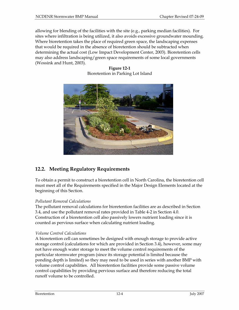
allowing for blending of the facilities with the site (e.g., parking median facilities). For sites where infiltration is being utilized, it also avoids excessive groundwater mounding. Where bioretention takes the place of required green space, the landscaping expenses that would be required in the absence of bioretention should be subtracted when determining the actual cost (Low Impact Development Center, 2003). Bioretention cells may also address landscaping/green space requirements of some local governments (Wossink and Hunt, 2003).
Figure 12-1 Bioretention in Parking Lot Island
12.2. Meeting Regulatory Requirements To obtain a permit to construct a bioretention cell in North Carolina, the bioretention cell must meet all of the Requirements specified in the Major Design Elements located at the beginning of this Section. Pollutant Removal Calculations The pollutant removal calculations for bioretention facilities are as described in Section 3.4, and use the pollutant removal rates provided in Table 4-2 in Section 4.0. Construction of a bioretention cell also passively lowers nutrient loading since it is counted as pervious surface when calculating nutrient loading. Volume Control Calculations A bioretention cell can sometimes be designed with enough storage to provide active storage control (calculations for which are provided in Section 3.4), however, some may not have enough water storage to meet the volume control requirements of the particular stormwater program (since its storage potential is limited because the ponding depth is limited) so they may need to be used in series with another BMP with volume control capabilities. All bioretention facilities provide some passive volume control capabilities by providing pervious surface and therefore reducing the total runoff volume to be controlled.
NCDENR Stormwater BMP Manual Chapter Revised 07-24-09
Bioretention 12-5 July 2007
12.3. Design Design is an eight-step process:
1. Understand basic layout concepts. 2. Determine the volume of water to treat. 3. Determine the surface area required. 4. Select the soil media type. 5. Decide the depth of soil media. 6. Size the underdrain pipes (if necessary). 7. Select the appropriate overflow or bypass method. 8. Select plants and mulch.
12.3.1. Step 1: Understand Basic Layout Concepts The layout of bioretention areas varies according to individual sites and to specific site constraints such as underlying soils, existing vegetation, drainage, location of utilities, sight distances for traffic, aesthetics, ease of maintenance, etc. Figure 12-1 illustrates a concept for a bioretention traffic island. These types of bioretention facilities typically take up no more space than what is required by typical zoning rules, and they provide stormwater treatment as well as site aesthetics. The following photographs are examples of existing bioretention cells that have been designed using these techniques. These cells blend into the landscape and appear to be typical flowerbeds or medians. Often, bioretention cells can be designed with flowering plants to enhance the landscape. Examples of Previously Installed Bioretention Cells Figure 12-2a shows an 8-inch gravel strip followed by 5 feet of grass for pretreatment along the side that receives water from the jogging trail. This is an example of both gravel strip pre-treatment design as well as when to maintain the gravel strip. This strip has become over-grown with grass and has been clogged with sediment. The mulch has also become thin, and should be replaced.
NCDENR Stormwater BMP Manual Chapter Revised 07-24-09
Bioretention 12-6 July 2007
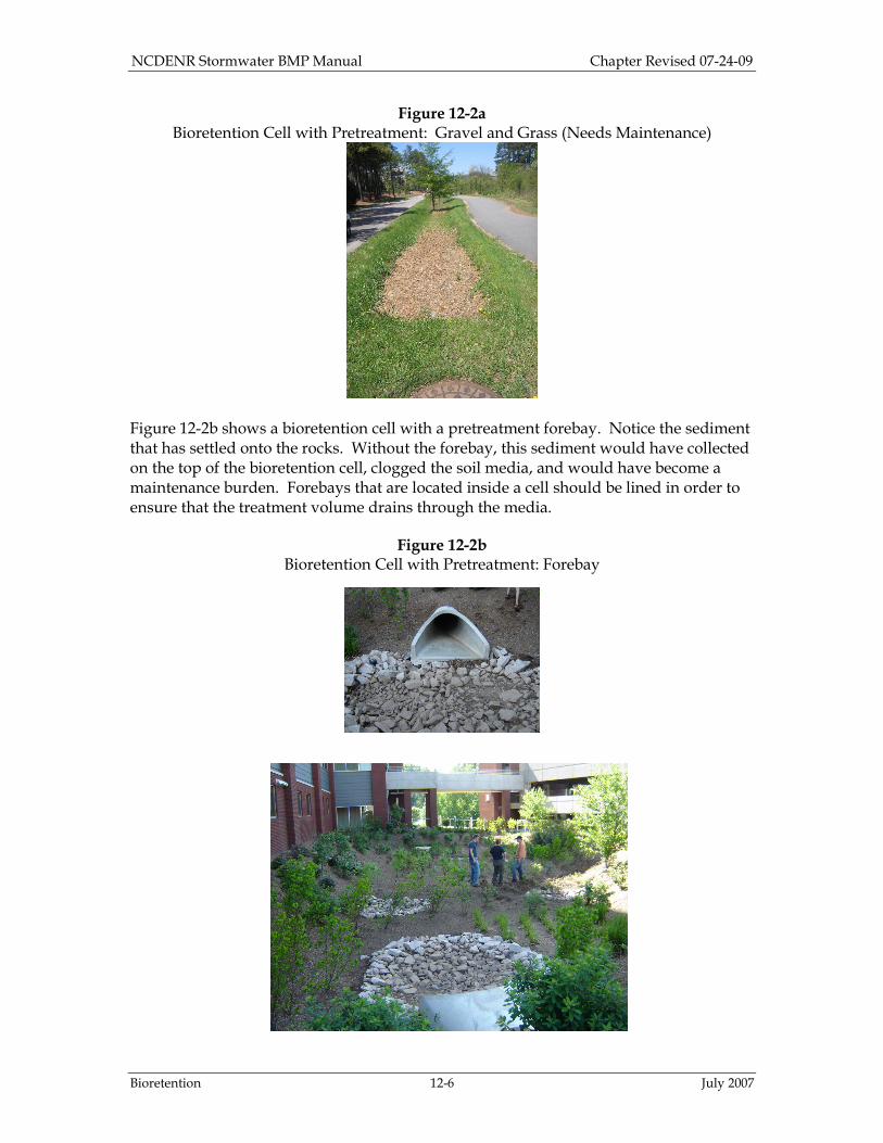
Figure 12-2a Bioretention Cell with Pretreatment: Gravel and Grass (Needs Maintenance)
Figure 12-2b shows a bioretention cell with a pretreatment forebay. Notice the sediment that has settled onto the rocks. Without the forebay, this sediment would have collected on the top of the bioretention cell, clogged the soil media, and would have become a maintenance burden. Forebays that are located inside a cell should be lined in order to ensure that the treatment volume drains through the media.
Figure 12-2b Bioretention Cell with Pretreatment: Forebay

NCDENR Stormwater BMP Manual Chapter Revised 07-24-09
Bioretention 12-7 July 2007
Examples of Additional Design Options Use of Flow Splitters Bioretention units can be designed using a flow splitter so that only the treatment volume is directed into the cell. An example of this design is provided in Figure 12-3a. This example shows a filter strip, though it is not required for every design. See Major Design Element #5. Please see Section 5.0 Common BMP Design Elements for more information on flow splitting devices.
Figure 12-3a
Typical Bioretention Cell Using a Flow Splitting Device

NCDENR Stormwater BMP Manual Chapter Revised 07-24-09
Bioretention 12-8 July 2007
Use of Overflow Devices Bioretention units can be designed using an overflow device so that water in excess of the treatment volume overflows to a filter strip. An example of this design is provided in Figure 12-3b. This example shows a filter strip, though it is not required for every design. See Major Design Element #5. Please see Section 5.0 Common BMP Design Elements for more information on flow splitting devices.
Figure 12-3b Typical Bioretention Cell Using an Overflow Device
Internal Water Storage Zones (IWS) An Internal Water Storage Zone (IWS) can be created by the addition of an elbow in the underdrain piping at a 90º angle vertically perpendicular to the horizontal underdrain, either in retrofit conditions or in new installations. This up-turned elbow on underdrains can force water to remain longer in the bottom of the cell, creating a saturated internal water storage zone (IWS). If this zone remains saturated long enough, anaerobic conditions are created, promoting denitrification and increased N removal (Passeport et al., 2009). There are several benefits to using upturned elbows and IWS. The IWS works for both pollutant and peak flow reduction as anaerobic conditions can be created to increase nitrogen removal. It also allows more water to infiltrate into the surrounding soils. If an upturned elbow is installed correctly in sufficiently permeable soils, it may only rarely generate outflows. The use of upturned elbows and an IWS is especially beneficial in

NCDENR Stormwater BMP Manual Chapter Revised 07-24-09
Bioretention 12-9 July 2007
the Sandhills and Coastal Plain where surrounding sandy soils can be ideal for infiltration, reducing outflows and surface water runoff. Additionally, upturned elbows can also be used in the Piedmont and Mountain areas of North Carolina when surrounding soils are of appropriate infiltration capacity. There can be a thermal benefit to IWS use as water is pulled from the coolest zone at the bottom of the cell. This is especially beneficial for temperature reductions in trout waters. Finally, there is often a cost benefit for using upturned elbows, both for new installations and retrofits. In new installations, there is a cost-savings associated with installation since the invert of the outlet is not as deep. Often with IWS there can be less trenching and fewer materials associated with using it. In retrofits, upturned elbows can be cheaply added to existing Bioretention cells where increased N & P removal rates are needed. Additionally, cells with IWS can be added as retrofits even in areas with restricted outlet depth. In order for an internal water storage zone to work correctly, the underlying soils must have some permeability. In general, if the underlying soils are Group A or B soils with a low clay content, then the IWS will be effective. If soils are too compacted, water will not infiltrate and may stagnate in the lower portion, causing problems for the BMP. Media depth above the bottom gravel and underdrain layer must be at least 3 feet. The top of IWS should be separated from the outlet and bowl surface by at least 12, but ideally 18 inches. See Figure 12-3c.
Figure 12-3c Bioretention Cell showing IWS Zones
Bioretention cells with a properly designed IWS and acceptable surrounding soils can receive increased N and P removal rates in the Coastal Plain and Sandhills (60% N reduction, 60% P reduction). In the Piedmont and Mountains, bioretention cells with a properly designed IWS can receive an increased credit for N-reduction (40%). Parking Lot Diversion Method A bioretention area that can be installed along the perimeter of a parking lot is shown in Figure 12-3c. The water is diverted to the bioretention area through the use of a curb diversion structure (see Section 5.0 Common BMP Design Elements for details). A 2-foot buffer between the curb and the bioretention area serves as pretreatment and reduces the possibility of drainage seeping under the pavement section and creating “frost

NCDENR Stormwater BMP Manual Chapter Revised 07-24-09
Bioretention 12-10 July 2007
heave” during winter months. Flow diversion by curb diversion structures may not meet the volume attainment requirements. A berm one foot in height separates the swale from the bioretention area. The bioretention area should be at an elevation such that when the design ponding depth is reached, additional flow continues down the swale and is diverted from the bioretention cell. The flow diversion method shown is for conceptual purposes and may not meet the volume attainment requirements. As for all bioretention designs, the diversion method must meet all of the Major Design Elements.
Figure 12-3d
Parking Edge and Perimeter with Curb Prince George’s County (2000a)
Bioretention Cells on Steep Slopes Figure 12-3d depicts a bioretention terrace that can be used in sloping terrain (for 10-20% slopes). An impermeable or very low permeability geomembrane must be used against the gabions or similar retaining structure to prevent flow from leaving the treatment unit through that surface. An underdrain could be placed at the low point of the filter if the native soil that the unit is built against will not provide adequate infiltration capacity.

NCDENR Stormwater BMP Manual Chapter Revised 07-24-09
Bioretention 12-11 July 2007
Figure 12-3e Bioretention Terrace Suitable for Use on Slopes 10-20%
Pretreatment Options Inflow must enter a bioretention cell via sheet flow (1ft/sec for cells with mulch, or 3.0 ft/sec for grassed cells) or alternative energy dissipating devices must be used. Sheet flow provides for the most even distribution of flow and the least energy (minimizing erosion). Sheet flow can be naturally provided as in the case of a gently sloping parking lot with no curb and gutter or a vegetated buffer/filter strip, or it can be designed into the device by the use of a level spreader. In some instances sheet flow is not attainable and the inflow will enter from concentrated sources such as curb diversion structures, drainage pipes, grassy swales, etc. In these cases a rip rap lined entrance, a forebay, or other energy-dissipating device must be used. The water treatment volume shall be calculated as specified in Section 3. The cell must be designed to have a pretreatment area. The most commonly used pretreatment devices are:
1.) A grass and gravel combination: This should consist of 8 inches of gravel followed by 3 to 5 feet of sod. In eastern and central North Carolina, centipede has been used successfully. In the mountains, fescue and bluegrass are appropriate.
2.) A grassed water quality swale: A water quality swale shall be designed as specified in Chapter 14.
3.) A forebay: The forebay should be 18-30 inches deep, and used only in areas where standing water is not considered a safety concern. The forebay should be deepest where water enters, and more shallow where water exits in order to dissipate hydraulic energy of the water flowing to the forebay. If there is a risk that water in the forebay could flow into the underdrain without first flowing to the cell, the forebay should also be lined.
Maintenance Considerations When performing the following remaining steps of designing a bioretention cell, consider how landscape professionals will later access the site for maintenance. Because the soil must be able to accommodate fast water infiltration, it can not be compacted by heavy equipment. Is the forebay accessible for heavy equipment to remove sediment from it without driving onto the cell? Are the clean-out pipes accessible? All aspects of design should consider future maintenance.

NCDENR Stormwater BMP Manual Chapter Revised 07-24-09
Bioretention 12-12 July 2007
Construction Sequencing The drainage area to the cell should be stabilized before cell construction begins in order to prevent clogging. For roadways draining to the cell, the subbase course (crusher run) and the base course layer of asphalt need to be in place prior to cell construction. If fines get washed into the excavated cell, they must be removed before building the cell in order to restore the in-situ soils permeability. It is recommended the cell media be covered with impermeable plastic during construction. 12.3.2. Step 2: Determine the Volume of Water to Treat Water Volume
An individual bioretention cell is intended to treat the first flush. Section 3, Stormwater
Calculations, details the volumetric calculation. Siting Issues Bioretention facilities shall not be used in areas with the following characteristics:
− The seasonal high water table is less than 2 feet below the bottom of the cell.
− Slopes are 20 percent or greater, unless bioretention terraces are planned.
− Further construction is planned on either the immediately surrounding site or in outparcels that may drain to the bioretention site. (The upstream contributing drainage area must be completely and permanently stabilized (e.g. gravel base course driving surface (preferably paved), or a dense and vigorous vegetative cover). The heavy sediment load from a bare earth construction site will cause premature failure of a bioretention BMP.)
− The cell is inaccessible for maintenance.
− The cell will not comply with local landscape ordinances. Contributing Drainage Basin
Consider the affect of large storms on potential erosion within the cell as well as potential
overflow and downhill erosion upon water leaving the cell. The contributing area to an
individual bioretention cell will typically be 5 acres or less because many large
watersheds will not have an area that is large enough to serve the treatment volume while
also being high enough above the water table. 12.3.3. Step 3: Determine the Surface Area and Depth Required The cell can be designed to hold the first inch of rainfall from the entire drainage area. The required surface area of the bioretention cell is equal to the required treatment volume (as calculated using the Simple Method) divided by the ponding depth. No dimension (width, length, or radius) can be less than 10 feet. This is to provide sufficient space for plants.

NCDENR Stormwater BMP Manual Chapter Revised 07-24-09
Bioretention 12-13 July 2007
12.3.4. Step 4: Select the Soil Media Type. The soil mix should be uniform and free of stones, stumps, roots or other similar material greater than 2 inches. It should be a homogenous soil mix of 85-88 percent by volume sand (USDA Soil Textural Classification), 8 to 12 percent fines (silt and clay), and 3 to 5 percent organic matter (such as peat moss) shall be used. Higher (12 percent) fines content should be reserved for areas where TN is the target pollutant. In areas where phosphorus is the target pollutant, lower (8 percent) fines should be used. Additionally, the phosphorus content of the soil mix should be low. Soil media should be sent to NC Department of Agriculture [NCDA] labs to be analyzed. The P-Index for bioretention soil media should always range between 10 and 30, regardless of the target pollutant (Hardy et. al., 2003 and Hunt et. al., 2006). The P-Index is an extremely important design element. Cells that are constructed of high P-Index soils can export phosphorus. The media should be tested to determine an actual drainage rate after placement. The permeability should fall between 1 and 6 inches per hour, and 1-2 inches per hour is preferred. As a rule of thumb, using the above-specified media, the infiltration rates should be approximately 2 in/hr and 1 in/hr for 8% and 12% fines, respectively, depending on the target pollutant. An estimated drainage rate for percent fines between 8 and 12 can be approximated during design by linear interpolation. If TSS or pathogens is the target pollutant, the higher permeability can be used because these two pollutants are removed on the surface of the bioretention cell rather than within the cell. 12.3.5. Step 5: Determine the Soil Media Depth Different pollutants are removed in various zones of the Bioretention cell using several mechanisms. TSS is removed both in pre-treatment and on the surface of the cell itself. For that reason, TSS removal is not a major factor in depth of the cell design. Depth is, however, an issue for other pollutants. Metals are removed in the top layer of mulch and the soil as they are often bound to sediment. Additionally, two thirds of phosphorus entering the cell is attached to soil particles. As a result, this portion is removed on the surface. The remaining third is soluble and is removed 12 inches or more below the surface. Bacterial, viral and protozoan pathogens can be killed on the surface and removed throughout the cell by several mechaisms: sun-exposure, drying, sedimentation, and filtration (Hathaway and Hunt, 2008). Temperature is reduced at approximately 48 inches below the surface. Nitrogen is removed 30 inches below the surface. Initial research at NC State shows that using an up-turned underdrain pipe may increase nitrogen removal. The up-turned piped creates an anaerobic zone that may facilitate nitrogen removal. Please see the Internal Water Storage (IWS) zone section of this chapter for more information. Consider the types of pollutants to be removed, and select an appropriate media depth. The ponding depth above the media and mulch shall be 12 inches or less (9 inches or less is preferred). This is based on both the typical inundation tolerance of the vegetation used in bioretention facilities, as well as the ability of the ponded water to drain into the soil within the required time.
NCDENR Stormwater BMP Manual Chapter Revised 07-24-09
Bioretention 12-14 July 2007
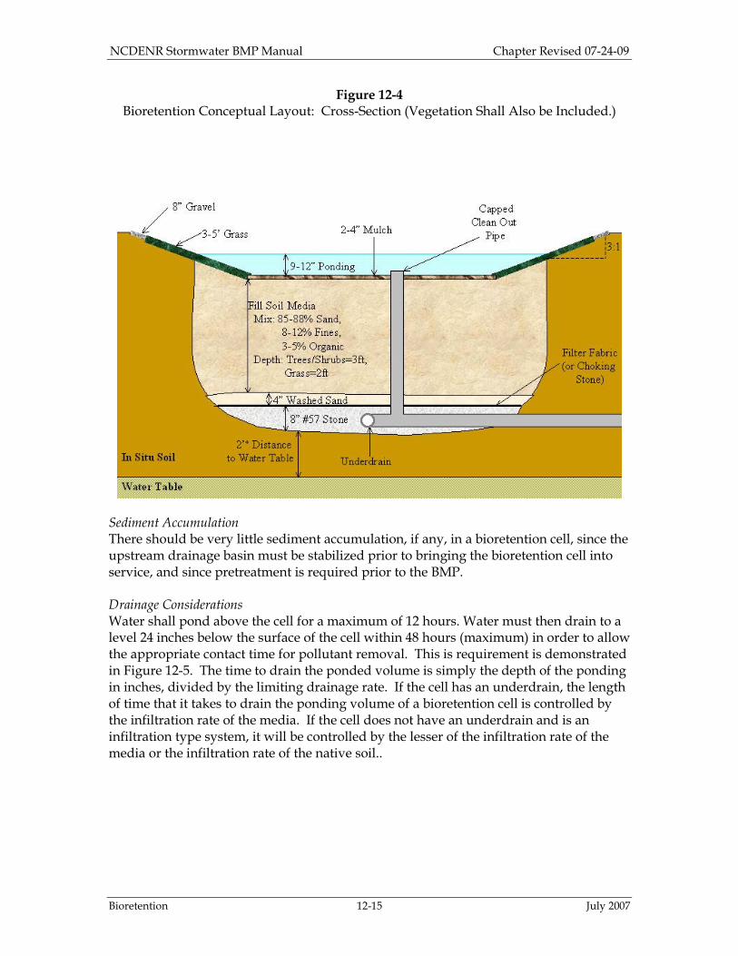
The depth of the media in a bioretention cell should be between 2 and 4 feet. This range reflects the fact that most of the pollutant removal occurs within the first 2 feet of soil and those excavations deeper than 4 feet become more expensive. The depth should accommodate the vegetation (shrubs or trees). If the minimum depth of 2 feet is used, then only shallow-rooted plants can be planted. Grassed bioretention cells with no IWS can be as shallow as 2 feet. However, if nitrogen is the target pollutant then the cell should have at least 30 inches of media because, as previously discussed, nitrogen is removed 30 inches below the surface. Bioretention facilities where shrubs or trees are planted can be as shallow as 3 feet. If large trees are to be planted in deep fill media, care should be taken to ensure that they would be stable and not fall over. As stated above, if IWS is used, cells must have a minimum depth of 3 feet. If underdrain piping is used (which is only for cases where the infiltration rate is less than 2 in/hr), then the media is as shown in Figures 12-4.. This figure shows a cross-sectional design. #57 stone shall be installed around the underdrain. Crusher run shall not be used around the underdrain as it can form an impermeable layer (Amerson et al., 1991). For pretreatment, the gravel and grass option is presented in this figure because it is the most commonly used pretreatment in North Carolina. The design shown here is for a bioretention cell in a non-developing area. Bioretention cells should only be used in non-developing areas. If there is any concern that the surrounding area may be developed in the future, then consider using an alternate BMP or protecting the BMP from sediment. If this is only a nominal concern, then use 2 inches of #8 or #89 washed choking stone in place of the filter fabric shown in Figure 12-4. For further information on designing bioretention cells with choking stone layers, consult Hunt and Lord, 2006. If an underdrain system is not used, the cross-sectional design of the cell will be the same although the underdrain will be omitted. Figure 12-4 is shown using the gravel and grass pretreatment option, though it could be modified to use any of the pretreatment methods. This figure also shows an overflow structure. Typically, an overflow structure is adapted from an existing drainage culvert inlet. In Figure 12-4, the vertical sides of the bioretention cell do not have to be at a specified angle. However, the surface area of the bottom of the cell should be maximized.
NCDENR Stormwater BMP Manual Chapter Revised 07-24-09
Bioretention 12-15 July 2007
Figure 12-4 Bioretention Conceptual Layout: Cross-Section (Vegetation Shall Also be Included.)
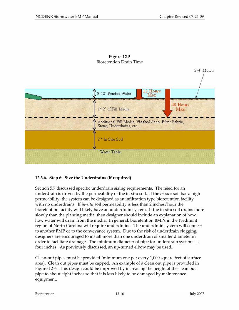
Sediment Accumulation There should be very little sediment accumulation, if any, in a bioretention cell, since the upstream drainage basin must be stabilized prior to bringing the bioretention cell into service, and since pretreatment is required prior to the BMP. Drainage Considerations Water shall pond above the cell for a maximum of 12 hours. Water must then drain to a level 24 inches below the surface of the cell within 48 hours (maximum) in order to allow the appropriate contact time for pollutant removal. This is requirement is demonstrated in Figure 12-5. The time to drain the ponded volume is simply the depth of the ponding in inches, divided by the limiting drainage rate. If the cell has an underdrain, the length of time that it takes to drain the ponding volume of a bioretention cell is controlled by the infiltration rate of the media. If the cell does not have an underdrain and is an infiltration type system, it will be controlled by the lesser of the infiltration rate of the media or the infiltration rate of the native soil..
NCDENR Stormwater BMP Manual Chapter Revised 07-24-09
Bioretention 12-16 July 2007
Figure 12-5 Bioretention Drain Time
12.3.6. Step 6: Size the Underdrains (if required) Section 5.7 discussed specific underdrain sizing requirements. The need for an underdrain is driven by the permeability of the in-situ soil. If the in-situ soil has a high permeability, the system can be designed as an infiltration type bioretention facility with no underdrains. If in-situ soil permeability is less than 2 inches/hour the bioretention facility will likely have an underdrain system. If the in-situ soil drains more slowly than the planting media, then designer should include an explanation of how how water will drain from the media. In general, bioretention BMPs in the Piedmont region of North Carolina will require underdrains. The underdrain system will connect to another BMP or to the conveyance system. Due to the risk of underdrain clogging, designers are encouraged to install more than one underdrain of smaller diameter in order to facilitate drainage. The minimum diameter of pipe for underdrain systems is four inches. As previously discussed, an up-turned elbow may be used.. Clean-out pipes must be provided (minimum one per every 1,000 square feet of surface area). Clean out pipes must be capped. An example of a clean out pipe is provided in Figure 12-6. This design could be improved by increasing the height of the clean out pipe to about eight inches so that it is less likely to be damaged by maintenance equipment.

NCDENR Stormwater BMP Manual Chapter Revised 07-24-09
Bioretention 12-17 July 2007
Figure 12-6 Bioretention Cell Clean Out Pipe, Less than the 8” Recommended Height
12.3.7. Step 7: Select the Appropriate Overflow Structure The overflow structure should be sized to accommodate storm volumes in excess of the first flush. The first available outlet on the outlet structure should therefore be placed at the height of the first flush, which is the ponded level of the bioretention cell. Use the weir equation to consider the height of the water above the weir during overflow from large storm events. Typically, water can rise about 2 inches above the ponded water level. But, this height can be higher, about 4-6” above the ponded water level, if required by design restraints. A particular design storm is not specified for overflow structure design. Professional judgment should be used when considering potential flooding risks outside of the bioretention cell. 12.3.8. Step 8: Select Plants and Mulch Plants are an integral element of the bioretention system’s pollutant removal and water filtration process. Plant roots aid in the physical and chemical bonding of soil particles necessary to form stable aggregates, improve soil structure, and increase infiltration capacity. Vegetated soils are more capable of more effective degradation, removal, and mineralization of total petroleum hydrocarbons (TPHs), polycyclic aromatic hydrocarbons (PAHs), pesticides, chlorinated solvents, and surfactants than are non-vegetated soils (US EPA 2000). The primary design considerations for plant selection include:
1. Soil moisture conditions: Soil moisture conditions will vary widely within the bioretention facility from saturated (bottom of cell) to relatively dry (rim of cell) as well as over time. Therefore, the predominant plant material utilized should be facultative species adapted to stresses associated with both wet and dry conditions (Prince Georges County, 2002). In some cases, the in-situ soil can be ripped and amended so that vegetation can grow.
2. Pollutant loadings: Since bioretention is often specified for use in impaired and/or nutrient sensitive watersheds, strategic use of particular plants for

NCDENR Stormwater BMP Manual Chapter Revised 07-24-09
Bioretention 12-18 July 2007
phytoremediation purposes is crucial. Plants should tolerate typical pollutants and loadings from the surrounding land uses.
3. Above and belowground infrastructure in and near the bioretention facility: Plant selection should consider the surrounding conditions including: light pollution tolerance, wind, above and below ground utilities. Slotted or perforated pipe should be more than 5 feet away from tree locations. Plants with taproots should not be used.
4. Adjacent plant communities and potential invasive species control. 5. Site distances and setbacks for roadway applications. 6. Visual buffering: Plants can be used to buffer structures from roads, enhance
privacy among residences, and provide an aesthetic amenity for the site. 7. Aesthetics: Visually pleasing plant designs add to the property and encourage
community and homeowner acceptance. Public education and participation in the plant selection and design should be encouraged to promote greater involvement in long-term care.
8. Grass may be used, however, grassed cells must be sodded (not seeded) and the sod must not be grown in soil that has an impermeable layer, such as clay.
Planting design will vary with the surrounding landscape context and design objectives. For example, the use of plants in bioretention areas could replicate a variety of native terrestrial ecosystems including forests, ornamental gardens, meadows, hedgerows, and wetlands, as well as wildlife habitats. A minimum of one (1) tree, three (3) shrubs, and three (3) herbaceous species should be incorporated in the bioretention planting plan unless it is a grassed cell. A diverse plant community is necessary to avoid susceptibility to insects and disease. A recommended minimum planting density is 400 stems/acre. Bacteria die-off occurs at the surface where stormwater is exposed to sunlight and the soil can dry out. Therefore it is best for bioretention cells to not be too densely vegetated in order to allow greater exposure to sunlight and consequent die-off of bacteria (NC Cooperative Extension, 2006). The plants selected should be able to tolerate typical stormwater pollutant loads, variable (often very dry) soil moisture, temporary submergence, and extended wet conditions. Bioretention facilities in the Piedmont and mountains tend to become wetter over time; coastal bioretention facilities tend to be very dry (plants suitable for xeriscapes may be more appropriate). Plants suitable for North Carolina BMP sites are listed in Table 12-1. The list of plant species is not exhaustive, and additional bioretention plant species may be suitable that are not shown in the table. Landscape design can add aesthetic appeal to stormwater treatment as shown in Figures 12-7a and 12-7b.
Figure 12-7a

NCDENR Stormwater BMP Manual Chapter Revised 07-24-09
Bioretention 12-19 July 2007
Aesthetic Appeal, Street Side Project (Courtesy of Stuart Patton Echols, Pennsylvania
State University)
Figure 12-7b
Aesthetic Appeal, Courtyard Project (Courtesy of Stuart Patton Echols, Pennsylvania State University)
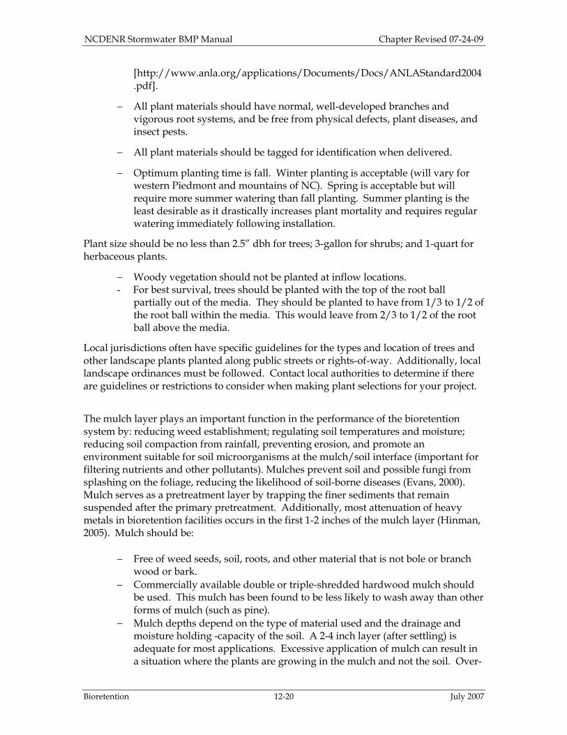
To increase survival rates and ensure quality of plant materials, the following general guidelines for plantings within bioretention facilities are recommended:
− All plant material should conform to the standards of the current edition of American Standard for Nursery Stock as approved by the American Standards Institute, Inc. All plant grades shall be those established by the current edition of American Standards for Nursery Stock
NCDENR Stormwater BMP Manual Chapter Revised 07-24-09
Bioretention 12-20 July 2007
[http://www.anla.org/applications/Documents/Docs/ANLAStandard2004.pdf].
− All plant materials should have normal, well-developed branches and vigorous root systems, and be free from physical defects, plant diseases, and insect pests.
− All plant materials should be tagged for identification when delivered.
− Optimum planting time is fall. Winter planting is acceptable (will vary for western Piedmont and mountains of NC). Spring is acceptable but will require more summer watering than fall planting. Summer planting is the least desirable as it drastically increases plant mortality and requires regular watering immediately following installation.
Plant size should be no less than 2.5” dbh for trees; 3-gallon for shrubs; and 1-quart for herbaceous plants.
− Woody vegetation should not be planted at inflow locations. - For best survival, trees should be planted with the top of the root ball
partially out of the media. They should be planted to have from 1/3 to 1/2 of the root ball within the media. This would leave from 2/3 to 1/2 of the root ball above the media.
Local jurisdictions often have specific guidelines for the types and location of trees and other landscape plants planted along public streets or rights-of-way. Additionally, local landscape ordinances must be followed. Contact local authorities to determine if there are guidelines or restrictions to consider when making plant selections for your project.
The mulch layer plays an important function in the performance of the bioretention system by: reducing weed establishment; regulating soil temperatures and moisture; reducing soil compaction from rainfall, preventing erosion, and promote an environment suitable for soil microorganisms at the mulch/soil interface (important for filtering nutrients and other pollutants). Mulches prevent soil and possible fungi from splashing on the foliage, reducing the likelihood of soil-borne diseases (Evans, 2000). Mulch serves as a pretreatment layer by trapping the finer sediments that remain suspended after the primary pretreatment. Additionally, most attenuation of heavy metals in bioretention facilities occurs in the first 1-2 inches of the mulch layer (Hinman, 2005). Mulch should be:
− Free of weed seeds, soil, roots, and other material that is not bole or branch wood or bark.
− Commercially available double or triple-shredded hardwood mulch should be used. This mulch has been found to be less likely to wash away than other forms of mulch (such as pine).
− Mulch depths depend on the type of material used and the drainage and moisture holding -capacity of the soil. A 2-4 inch layer (after settling) is adequate for most applications. Excessive application of mulch can result in a situation where the plants are growing in the mulch and not the soil. Over-

NCDENR Stormwater BMP Manual Chapter Revised 07-24-09
Bioretention 12-21 July 2007
mulched plants are easily damaged during periods of drought stress. Mulching in an area that is poorly-drained can aggravate the condition (Evans, 2000).
− Mulch can be applied any time of year, however, the best time to mulch is late spring after the soil has warmed.
− At least 6 months old (12 months is ideal).
− Uniformly placed about 3 inches deep.
− Renewed as needed to maintain a 2-4” depth; on previously mulched areas, apply a one-inch layer of new material. Added 1-2 times per year and completely removed/replaced once every two years.
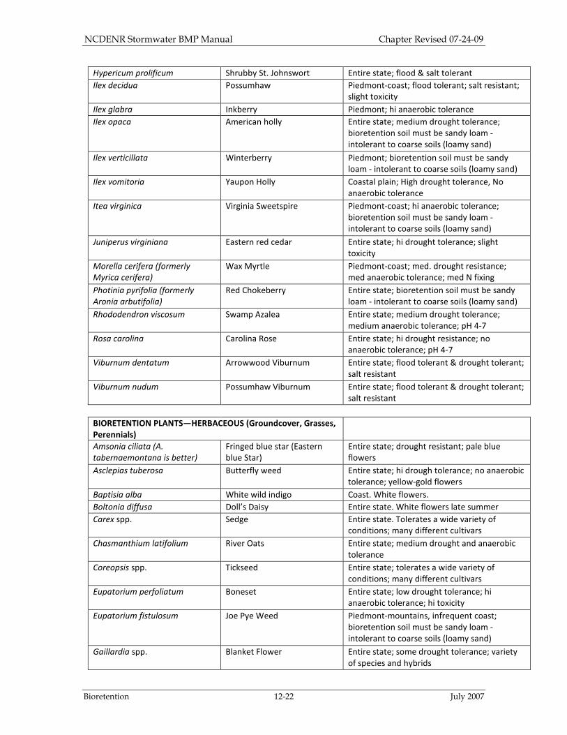
Table 12-1
BIORETENTION PLANTS—TREES
Latin Name Common Name Comments
Amelanchier arborea Common serviceberry Mountains/piedmont/inner coastal plain; (ht:
25-50ft)
Amelanchier laevis Allegheny serviceberry Mountains only; (ht: 30-40ft)
Betula nigra River Birch Entire state. Bioretention soil must be sandy
loam. Intolerant to coarse soils (loamy sand);
(ht: 50-75ft)
Chionanthus virginicus White Fringetree Entire state; (ht: 25-50ft)
Pinus palustris Longleaf pine Eastern piedmont/coast; soil pH 6-7; (ht: 75-
120ft)
Pinus taeda Loblolly pine Entire state; high anaerobic tolerance
Rhododendron maximum Great laurel Western piedmont/mountains; hi drought
resistance; Low soil pH (4-5.5) required; (ht:
25-35ft)
Taxodium distichum Bald cypress Piedmont to Coast; wet-moist soils; low
drought resistance; not salt tolerant; (ht: 25-
50ft)
BIORETENTION PLANTS—
SHRUBS
Betula lenta Cherry Birch Piedmont-coast; med. drought resistance; no
anaerobic tolerance
Callicarpa americana American Beautyberry Entire state; no anaerobic tolerance
Ceanothus americanus Jerseytea Ceanothus Entire state; no anaerobic tolerance; hi
drought tolerance; low N fixing
Clethra alnifolia Summersweet Clethra Piedmont-Coastal Plain; flood and salt
tolerance
Cornus amomum Silky Dogwood Entire state; Flood tolerant
Cyrilla racemiflora Swamp Cyrilla (ti-ti) Entire state; medium anaerobic tolerance;
medium drought tolerance, some salt
tolerance
Hamamelis virginiana Witchhazel Entire state; bioretention soil must be sandy
loam - intolerant to coarse soils (loamy sand)
Hypericum densiflorum Dense Hypericum Entire state; flood & salt tolerant
NCDENR Stormwater BMP Manual Chapter Revised 07-24-09
Bioretention 12-22 July 2007
Hypericum prolificum Shrubby St. Johnswort Entire state; flood & salt tolerant
Ilex decidua Possumhaw Piedmont-coast; flood tolerant; salt resistant;
slight toxicity
Ilex glabra Inkberry Piedmont; hi anaerobic tolerance
Ilex opaca American holly Entire state; medium drought tolerance;
bioretention soil must be sandy loam -
intolerant to coarse soils (loamy sand)
Ilex verticillata Winterberry Piedmont; bioretention soil must be sandy
loam - intolerant to coarse soils (loamy sand)
Ilex vomitoria Yaupon Holly Coastal plain; High drought tolerance, No
anaerobic tolerance
Itea virginica Virginia Sweetspire Piedmont-coast; hi anaerobic tolerance;
bioretention soil must be sandy loam -
intolerant to coarse soils (loamy sand)
Juniperus virginiana Eastern red cedar Entire state; hi drought tolerance; slight
toxicity
Morella cerifera (formerly
Myrica cerifera)
Wax Myrtle Piedmont-coast; med. drought resistance;
med anaerobic tolerance; med N fixing
Photinia pyrifolia (formerly
Aronia arbutifolia)
Red Chokeberry Entire state; bioretention soil must be sandy
loam - intolerant to coarse soils (loamy sand)
Rhododendron viscosum Swamp Azalea Entire state; medium drought tolerance;
medium anaerobic tolerance; pH 4-7
Rosa carolina Carolina Rose Entire state; hi drought resistance; no
anaerobic tolerance; pH 4-7
Viburnum dentatum Arrowwood Viburnum Entire state; flood tolerant & drought tolerant;
salt resistant
Viburnum nudum Possumhaw Viburnum Entire state; flood tolerant & drought tolerant;
salt resistant
BIORETENTION PLANTS—HERBACEOUS (Groundcover, Grasses,
Perennials)
Amsonia ciliata (A.
tabernaemontana is better)
Fringed blue star (Eastern
blue Star)
Entire state; drought resistant; pale blue
flowers
Asclepias tuberosa Butterfly weed Entire state; hi drough tolerance; no anaerobic
tolerance; yellow-gold flowers
Baptisia alba White wild indigo Coast. White flowers.
Boltonia diffusa Doll’s Daisy Entire state. White flowers late summer
Carex spp. Sedge Entire state. Tolerates a wide variety of
conditions; many different cultivars
Chasmanthium latifolium River Oats Entire state; medium drought and anaerobic
tolerance
Coreopsis spp. Tickseed Entire state; tolerates a wide variety of
conditions; many different cultivars
Eupatorium perfoliatum Boneset Entire state; low drought tolerance; hi
anaerobic tolerance; hi toxicity
Eupatorium fistulosum Joe Pye Weed Piedmont-mountains, infrequent coast;
bioretention soil must be sandy loam -
intolerant to coarse soils (loamy sand)
Gaillardia spp. Blanket Flower Entire state; some drought tolerance; variety
of species and hybrids

NCDENR Stormwater BMP Manual Chapter Revised 07-24-09
Bioretention 12-23 July 2007
Hemerocallis fulva Daylily Entire state; drought resistant
Heuchera americana Coral bells Entire state; many different cultivars
Juncus effusus Soft rush Entire state; medium drought and anaerobic
tolerance
Liatris spicata Dense blazing star Piedmont-mountains; bioretention soil must
be sandy loam - intolerant to coarse soils
(loamy sand)
Lobelia cardinalis Cardinal flower Entire state; drought resistant; bioretention
soil must be sandy loam - intolerant to coarse
soils (loamy sand)
Monarda sp. Bee Balm Piedmont-mtns most species; many cultivars
Osmunda cinnamomea Cinnamon fern Entire state; bioretention soil must be sandy
loam - intolerant to coarse soils (loamy sand)
Panicum virgatum Switchgrass Entire state, few mtns; drought resistant
Pennisetum sp. Fountain grass Piedmont-coast; many cultivars
Penstemon sp. Beard’s Tongue Piedmont-coast; many cultivars
Solidago canadensis Goldenrod Entire state; medium drought and anaerobic
tolerance
Solidago sempervirens Seaside goldenrod Coast; salt tolerant; drought tolerant
Sorghastrum nutans Indiangrass Entire state; drought tolerant
Spiraea tomentosa Steeplebush Entire state; drought tolerant; pink flowers
Verbena sp. Verbena Variable locations; cultivar tolerances vary
Note: Grass should never be seeded, use sod instead. When using sod, avoid sod that is grown in soil that has an impermeable layer (such as clay). Hybrid bermuda grass and centipede have been successfully tested as grassed bioretention cells in North Carolina. Centipede is recommended for warm climates. Fescue/bluegrass mix is recommended for colder climates.
Maintenance 12.4.1. Common Maintenance Issues Bioretention facilities require plant, soil, mulch, and under-drain maintenance to ensure optimal infiltration, storage, and pollutant removal capabilities. Bioretention maintenance requirements are typical landscape care procedures and include:
1. Watering: Plants should be selected to be tolerant of the bioretention facility’s particular conditions. Watering should not be required after establishment (about 2 to 3 years). However, watering may be required during prolonged dry periods after plants are established.
2. Erosion Control: Inspect flow entrances, ponding area, and surface overflow areas periodically. Replace soil, plant material, and/or mulch in areas where erosion has occurred. Erosion problems should not occur with proper design except during extreme weather events. If erosion problems do occur, the following issues should be re-assessed: flow volumes from the contributing drainage area and bioretention size; flow velocities and gradients within the bioretention facility; flow dissipation and erosion protection methods in the pretreatment and

NCDENR Stormwater BMP Manual Chapter Revised 07-24-09
Bioretention 12-24 July 2007
in-flow areas. If sediment is deposited in the bioretention facility, immediately determine the source, remove excess deposits, and correct the problem.
3. Plant Material: Depending on plants selected and aesthetic requirements, occasional pruning and removal of dead plant material may be necessary. Replace all dead plants. However, if specific plants consistently have a high mortality rate, assess the cause and replace with appropriate species. Periodic weeding is necessary until groundcover plants are established. Weeding should become less frequent if an appropriate plant density has been used.
4. Nutrients and Pesticides: The soil media and plant material should have been selected for optimum fertility, plant establishment, and growth within the particular conditions of each bioretention facility. Nutrient and pesticide inputs should NOT be required and will degrade the pollutant processing capability of the bioretention facility, as well as contribute to additional pollutant loading to receiving waters. By design, bioretention facililities are typically specified in watersheds where phosphorous and nitrogen levels are often elevated. Therefore, these should not be limiting nutrients with regard to plant health. If in question, have the soil analyzed for fertility.
5. Mulch: Replace mulch annually in bioretention facilities where heavy metal deposition is likely (e.g., drainage areas that include commercial/industrial uses, parking lots, or roads). In residential or other settings where metal deposition is not a concern, replace or add mulch as needed to maintain a 2 to 4 inch depth at least once every two years.
6. Soil media: Soil mixes for bioretention facilities are design to maintain long-term fertility and pollutant processing capability. Estimates from metal attenuation research indicates that metal accumulation should not present a toxicity concern for at least 20 years in bioretention facilities (USEPA 2000). Further, replacing mulch where heavy metal deposition is likely provides an additional factor of safety for prolonged bioretention performance. If in question, have soil analyzed for fertility and pollutant levels.
When the filtering capacity diminishes substantially (e.g., when water ponds on the surface for more than 12 hours), remedial actions must be taken. One possible problem is that underdrain pipe systems can become clogged. Annual flushing through pipe cleanouts is recommended to facilitate unclogging of the pipes without disturbing the bioretention areas. If the water still ponds for more than 12 hours, the top few inches of material should be removed and replaced with fresh material. The removed sediments should be disposed of in an acceptable manner (e.g., landfill). If that does not solve the problem, more extensive rebuilding is required.

NCDENR Stormwater BMP Manual Chapter Revised 07-24-09
Bioretention 12-25 July 2007
Examples of When to Perform Maintenance
• Replace gravel when it has become clogged with sediment.
Figure 12-8a Gravel Pretreatment is Clogged with Sediment
• Replace mulch when it becomes thin or is taken over by grass.
Figure 12-8b Thin Mulch in the Bioretention Cell
• Remove top layer of fill media when the pool does not drain quickly. The pool is designed to drain within 12 hours.

NCDENR Stormwater BMP Manual Chapter Revised 07-24-09
Bioretention 12-26 July 2007
12.4.2. Sample Operation and Maintenance Provisions Important operation and maintenance procedures:
− Immediately after the bioretention cell is established, the plants will be watered twice weekly if needed until the plants become established (commonly six weeks).
− Snow, mulch or any other material will NEVER be piled on the surface of the bioretention cell.
− Heavy equipment will NEVER be driven over the bioretention cell.
− Special care will be taken to prevent sediment from entering the bioretention cell.
− Once a year, a soil test of the soil media will be conducted. After the bioretention cell is established, I will inspect it once a month and within 24 hours after every storm event greater than 1.0 inches (or 1.5 inches if in a Coastal County). Records of operation and maintenance will be kept in a known set location and will be available upon request. Inspection activities shall be performed as follows. Any problems that are found shall be repaired immediately.
Table 12-2
Sample Operation and Maintenance Provisions for Bioretention Areas
BMP element: Potential problems: How to remediate the problem: The entire BMP Trash/debris is present. Remove the trash/debris.
The perimeter of the bioretention cell
Areas of bare soil and/or erosive gullies have formed.
Regrade the soil if necessary to remove the gully, and then plant a ground cover and water until it is established. Provide lime and a one-time fertilizer application.
The inlet device: pipe, stone verge or swale
The pipe is clogged (if applicable).
Unclog the pipe. Dispose of the sediment off-site.
The pipe is cracked or otherwise damaged (if applicable).
Replace the pipe.
Erosion is occurring in the swale (if applicable).
Regrade the swale if necessary to smooth it over and provide erosion control devices such as reinforced turf matting or riprap to avoid future problems with erosion.
Stone verge is clogged or covered in sediment (if applicable).
Remove sediment and clogged stone and replace with clean stone.
NCDENR Stormwater BMP Manual Chapter Revised 07-24-09
Bioretention 12-27 July 2007
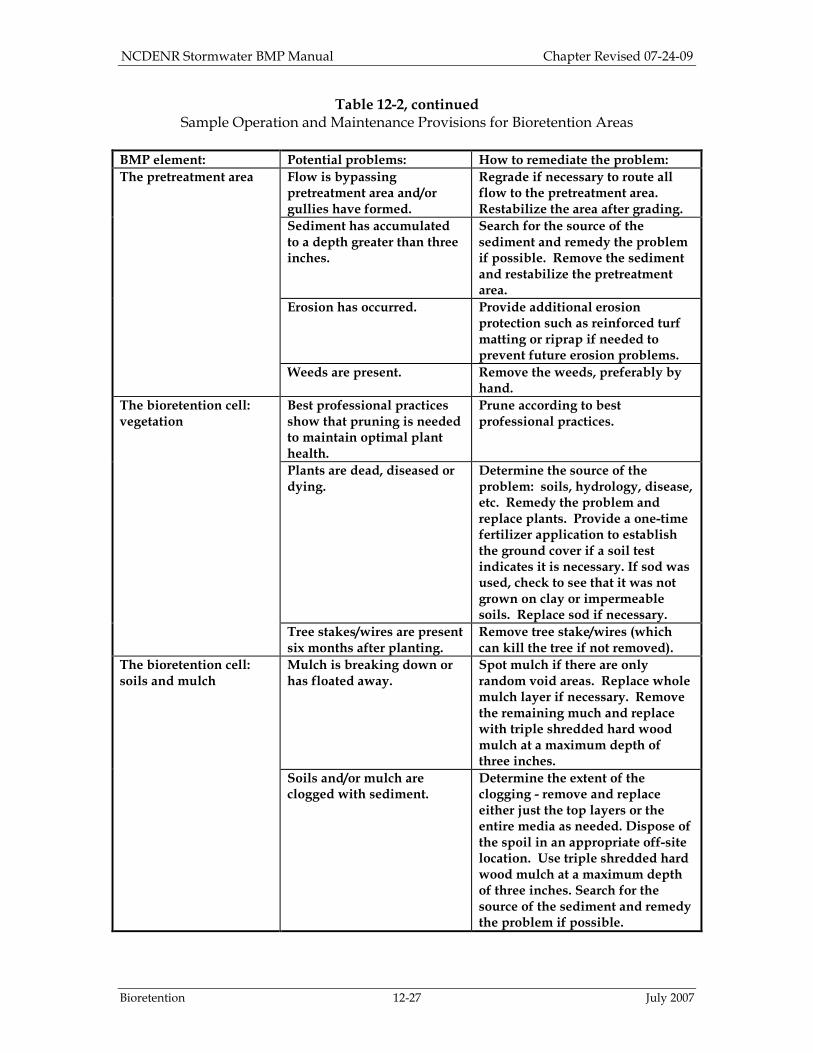
Table 12-2, continued Sample Operation and Maintenance Provisions for Bioretention Areas
BMP element: Potential problems: How to remediate the problem:
The pretreatment area Flow is bypassing pretreatment area and/or gullies have formed.
Regrade if necessary to route all flow to the pretreatment area. Restabilize the area after grading.
Sediment has accumulated to a depth greater than three inches.
Search for the source of the sediment and remedy the problem if possible. Remove the sediment and restabilize the pretreatment area.
Erosion has occurred. Provide additional erosion protection such as reinforced turf matting or riprap if needed to prevent future erosion problems.
Weeds are present. Remove the weeds, preferably by hand.
The bioretention cell: vegetation
Best professional practices show that pruning is needed to maintain optimal plant health.
Prune according to best professional practices.
Plants are dead, diseased or dying.
Determine the source of the problem: soils, hydrology, disease, etc. Remedy the problem and replace plants. Provide a one-time fertilizer application to establish the ground cover if a soil test indicates it is necessary. If sod was used, check to see that it was not grown on clay or impermeable soils. Replace sod if necessary.
Tree stakes/wires are present six months after planting.
Remove tree stake/wires (which can kill the tree if not removed).
The bioretention cell: soils and mulch
Mulch is breaking down or has floated away.
Spot mulch if there are only random void areas. Replace whole mulch layer if necessary. Remove the remaining much and replace with triple shredded hard wood mulch at a maximum depth of three inches.
Soils and/or mulch are clogged with sediment.
Determine the extent of the clogging - remove and replace either just the top layers or the entire media as needed. Dispose of the spoil in an appropriate off-site location. Use triple shredded hard wood mulch at a maximum depth of three inches. Search for the source of the sediment and remedy the problem if possible.
NCDENR Stormwater BMP Manual Chapter Revised 07-24-09
Bioretention 12-28 July 2007
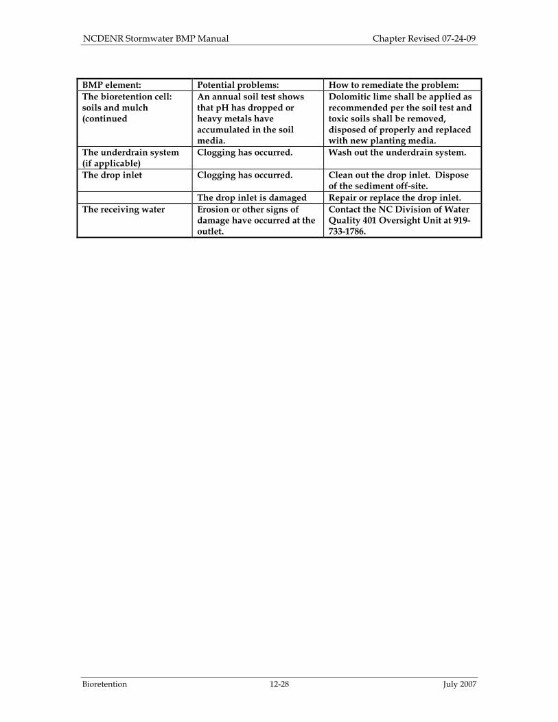
BMP element: Potential problems: How to remediate the problem:
The bioretention cell: soils and mulch (continued
An annual soil test shows that pH has dropped or heavy metals have accumulated in the soil media.
Dolomitic lime shall be applied as recommended per the soil test and toxic soils shall be removed, disposed of properly and replaced with new planting media.
The underdrain system (if applicable)
Clogging has occurred. Wash out the underdrain system.
The drop inlet Clogging has occurred. Clean out the drop inlet. Dispose of the sediment off-site.
The drop inlet is damaged Repair or replace the drop inlet.
The receiving water Erosion or other signs of damage have occurred at the outlet.
Contact the NC Division of Water Quality 401 Oversight Unit at 919-733-1786.
NCDENR Stormwater BMP Manual Chapter Revised 07-24-09
Bioretention 12-29 July 2007
September 28, 2007 Changes: 1. Major Design Elements:
i. Reformatted to include numbered requirements. ii. Defined sheet flow at 1 ft/sec. iii. Replaced “minimum” with “maximum” and “0.5” with “0.52” in, “Ponded water
shall completely drain into the soil within 12 hours. It shall drain to a level of 24 inches below the soil surface in a maximum of 48 hours. Permeability of 0.52-6”per hour is required, 1-2 in per hour is preferred.” Also clarified that the permeability referenced here is for the media, not the in-situ soil. Separated the second sentence into a separate requirement because the Administrative Code [15A NCAC 02H .1008(d)(6)] requires 0.52 in/hr.
iv. Divided, “Bioretention facilities shall not be used where: seasonally high water table less than 2 feet below bottom of BMP, slopes greater than 20%, and non-permanently stabilized drainage areas,” into two requirements. It now reads:
1. “Bioretention facilities shall not be used where the seasonally high water table is less than 2 feet below bottom of BMP.” This is per 15A NCAC 02H .1008(d)(3), an Administrative Code requirement for infiltration systems.
2. “Bioretention facilities shall not be used where slopes are greater than 20%, or in non-permanently stabilized drainage areas.” This is based on NC DWQ policy.
v. Added a requirement that the design shall be located a minimum of 30 feet from surface waters, and 50 feet from Class SA waters per 15A NCAC 02H .1008(d)(1).
vi. Added a requirement that the design shall be located a minimum of 100 feet from water supply wells per 15A NCAC 02H .1008(d)(2).
vii. Added a requirement that the volume in excess of the design volume, as determined from the design storm, shall bypass the cell per 15A NCAC 02H .1008(d)(4).
viii. Added a requirement that the volume in excess of the design volume shall be evenly distributed across a minimum 30 feet long vegetative filter strip. (A 50-ft filter is required in some locations.) If this can not be attained, alternate designs will be considered on a case by case basis. This requirement is per 15A NCAC 02H .1008(c)(4) and 15A NCAC 02H .1005(b)(iii).
2. 12.3.1: Clarified language to support the two Major Design Elements discussed in (1)(iv), (1)(vii) and (1)(viii) above.
3. 12.3.1: Removed a reference to the Simple Method, and specified that the treatment volume shall be calculated as specified in Section 3.
4. 12.3.1: Removed the reference to “online” bioretention cells where all of the water is directed to the cell.
5. 12.3.1: Clarified the discussion of the forebay pretreatment option. 6. 12.3.1: Clarified that sheet flow is defined as 1 ft/sec. 7. 12.3.1: Removed the reference to the first flush. 8. 12.3.5: Replaced “minimum” with “maximum” in the following sentence, “The ponded
water must drain to a level 24 inches below the surface of the cell within a maximum of 48 hours in order to allow the appropriate contact time for pollutant removal.”
9. 12.3.6: Replaced “shall” with “will likely” in, “If the in-situ soil permeability is less than 2 in/hour the bioretention facility will likely have an underdrain system.”
10. 12.3.6: Added, “If the in-situ soil drains more slowly than the planting media, then designers should explain how the water would drain from the media. Underdrains will likely be installed.”
11. 12.3.6: Added a reference to Section 5.7 for more information on underdrain requirements.
12. 12.3.8: Clarified that the stated planting density is recommended unless the design is a grassed bioretention cell.
NCDENR Stormwater BMP Manual Chapter Revised 07-24-09
Bioretention 12-30 July 2007
13. 12.3.8: Noted that hybrid bermudagrass and centipede sod have been successfully tested in bioretention cells in North Carolina.
14. Figure 12-2c: Altered for clarification. (A portion of this figure was deleted.) 15. Figure 12-3a: Altered for clarification. This is the flow-splitter option. (Renumbered.
Previously 12-3c). 16. Figure 12-3b: Added for clarification. This is the overflow device option. 17. Figure 12-3c: Deleted for clarification. 18. Figure 12-3d: Renumbered. Previously 12-3b. This is the steep slopes option. 19. Figures 12-4a, 12-4b, and 12-4c: Deleted. 20. Figure 12-4: Altered for clarification. (Renumbered. Previously 12-5). 21. Figure 12-5: Replaced “minimum” with “maximum” in the 48-hour requirement.
Renumbered. Previously 12-6. 22. Figure 12-6: Renumbered. Previously 12-7. 23. Figures 12-7a and 12-7b: Renumbered. Previously 12-8a and 12-8b. 24. Figures 12-8a and 12-8b: Renumbered. Previously 12-9a and 12-9b. 25. Table 12-1: Added recommended planting density. 26. Table 12-2: Renumbered. Previously Table 12-1.
July 14, 2009 Changes:
1. Revised first paragraph of section 12.3.5 per updated publication from NCSU. 2. Added information and pollutant removal credits regarding Internal Water Storage
Zones. 3. Added grassed cells must be sodded, not seeded. Grass must be grown on non-
impervious base soil. 4. Added recommendation to add impermeable plastic cover over media during
construction. 5. Table 12-1 was removed 6. Planting list was revised.