ch-4 series fire pumps overhaul instructions · pdf fileinstallation sleeve part no. 52880....
TRANSCRIPT

Read through the safety informationand overhaul instructions carefullybefore repairing your Waterous CH-4Series Fire Pump.
Table of Contents
Introduction 2. . . . . . . . . . . . . . . . . . . . . . . . . . . . . . . . . . . . . . . . . . . . . . . . . . .
Ordering Repair Parts 2. . . . . . . . . . . . . . . . . . . . . . . . . . . . . . . . . . . . . . . . . .
Tools Available from Waterous 2. . . . . . . . . . . . . . . . . . . . . . . . . . . . . . . . . .
Safety Information 3. . . . . . . . . . . . . . . . . . . . . . . . . . . . . . . . . . . . . . . . . . . . . .
General Overhaul Information 5. . . . . . . . . . . . . . . . . . . . . . . . . . . . . . . . . . .
Pump Overhaul:
Complete Disassembly of Pump See Table A on Page 6. . . . . . . . . . . .
Replacement of Mechanical Seals or Packing without Disassembling the pump See Table B on Page 6. . . . . . . . . . . .
K Series Transmission Overhaul See F-1031, Section 4309. . . . . . . . .
Cross-Section Diagrams of Pumps:
Pumps with Mechanical Seals:
Model CHK-4 33. . . . . . . . . . . . . . . . . . . . . . . . . . . . . . . . . . . . . . . . . . . . .
Model CHD-4 34. . . . . . . . . . . . . . . . . . . . . . . . . . . . . . . . . . . . . . . . . . . . .
Pumps with Packing:
Model CHK-4 35. . . . . . . . . . . . . . . . . . . . . . . . . . . . . . . . . . . . . . . . . . . . .
Model CHD-4 36. . . . . . . . . . . . . . . . . . . . . . . . . . . . . . . . . . . . . . . . . . . . .
NOTE: Instructions subject to change without notice
Model CHK-4, Transmission Driven
(The pump is turned by a K-Series Transmissionmounted directly to the pump.)
Model CHD-4, Direct Drive
(The pump is turned by a companion flange onthe impeller shaft.)
Waterous Company, 125 Hardman Avenue South, South St. Paul, Minnesota 55075 USA (651) 450-5000
www.waterousco.com
F-1031, Section 4316 (Issued: 07/12/12 )
CH-4 Series Fire Pumps
Overhaul Instructions

F-1031, Section 4316 Page 2 of 36
IntroductionThis instruction provides the necessary steps to overhaul CH-4 Series Fire Pumps.
If the entire pump is being overhauled, see Table A on Page 6.
If only the pump seals are being replaced, see Table B on Page 6.
CHK-4 Transmission Drives Only:
This instruction covers the removal of K Series Transmission from the pump only. For transmission overhaul instructions, see separate instruction F-1031, Section4309. Follow the instructions for Extra Heavy Duty Transmissions.
Ordering Repair PartsWhen ordering repair parts, furnish the reference number of the component (from Service Parts List) along with the Pump Model and Serial Number.
Refer to the Service Parts List furnished with your pump for identification if individual components.
The following repair kits are available for servicing the components identified:
Component Pump Model Seal Location Pump Material Repair Kit Includes:
Mechanical Seal
CHK-4
Drive EndIron K 674
One Mechanical Seal,Bearing and Oil Seal
Bronze K 674-2
Outboard Bearing EndIron K 702-4
Bronze K 702-5
CHD-4
Drive EndIron K 674-7
Bronze K 674-8
Outboard Bearing EndIron K 702-4
Bronze K 702-5
Packing CHK-4 or CHD-4 Drive and Outboard Ends Iron or Bronze K 667-6(10) Rings,
(5) for each end
F-1031, Section 4316 Page 3 of 36
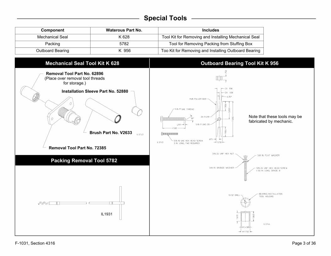
Special Tools
Component Waterous Part No. Includes
Mechanical Seal K 628 Tool Kit for Removing and Installing Mechanical Seal
Packing 5782 Tool for Removing Packing from Stuffing Box
Outboard Bearing K 956 Too Kit for Removing and Installing Outboard Bearing
Mechanical Seal Tool Kit K 628 Outboard Bearing Tool Kit K 956
Packing Removal Tool 5782
IL1931
Note that these tools may befabricated by mechanic.
Removal Tool Part No. 62896(Place over removal tool threads
for storage.)
Removal Tool Part No. 72385
Brush Part No. V2633
Installation Sleeve Part No. 52880

F-1031, Section 4316 Page 4 of 36
Safety Information
Please read through the safety information and operating instructions carefully before using your Waterous Fire Pump.
WARNING!
Death or serious personal injury might occur if proper operating proceduresare not followed. The pump operator, as well as individuals connecting supplyor discharge hoses to the apparatus must be familiar with these pump operating instructions as well as other operating instructions and manuals for the apparatus, water hydraulics and component limitation.
WARNING!
Pressure Hazard. May result in personal injury.
Prior to connection or removal of hoses, caps or other closures with pump intake or pump discharge connections, relieve pressure by opening drains orbleeder valves. Bleeder valves should also be used while filling a hose connected to an intake with water.
WARNING!
Scalding Water Hazard. May result in serious burns.
When operating the pump, be sure to open at least one discharge valve slightly to prevent the pump from overheating. If the pump runs for a few minutescompletely closed, it may heat the water enough to scald someone when thevalve is opened. Overheating can damage the packing, seals and other pumpparts. If the apparatus builder has installed a by-pass system or other provision designed to prevent overheating, opening a discharge valve may be unnecessary.
WARNING!
Unexpected Truck Movement. May result in serious personal injury ordeath.
Failure to properly shift transmission in accordance to the transmission operating instructions may result in unexpected truck movement which may resultin serious personal injury or death.
WARNING!
�������� ����� ������ �� ���������� ����� ��������� ��� ������ �� �������� �������� ������ �� ������
���� ��� ������� ��� ������� ����� ��� ����� ��� ������ ������ ����� �������� ����� �� ������ ������� �� �� ����� ������� ����� ������������
WARNING!
Packing Gland and Pump Body Temperature Hazard. May result in serious burns.
Heat is dissipated through the cross-section of the packing, transferring theheat to the packing gland and pump body.
F-1031, Section 4316 Page 5 of 36
General Overhaul Information
Tools and Equipment
The following tools and equipment may be needed to overhaul a pump:
1. Usual automotive mechanic's hand tools.
2. An arbor press for assembling or disassembling components.
3. An engine lathe for turning impeller hubs.
4. A suitable hoist and slings.
5. Torque capability up to 325 lb-ft.
While no special tools and equipment are required, a few special items areillustrated or described so the mechanic can make them or they are availablefrom the apparatus manufacturer or the Waterous Company. These specialitems are not absolutely necessary, but they will make the mechanic's workmuch easier.
Preliminary Testing
Before disassembling a pump, test it thoroughly, if possible, and record theresults. A comparison of this test with periodic tests recommended in formF-1031, Section 1000 can often reveal specific pump troubles. Excessivespeed, for instance, indicates that impellers and/or wear rings are probablyworn.
Cleaning
The continued satisfactory operation of a pump depends to a great extentupon the cleanliness of its internal parts. Sand, dirt or other abrasive materialwill wear gears and related parts. Before disassembling a pump for repairs, besure to clean its exterior. Make sure the working space, benches and tools areclean. Use only clean, lint-free cloths to wipe off components. Before reassembling a pump or its components, be sure to clean them thoroughly.
Pump Bodies and Impellers
Flush out these components and related parts with clean water and removeloose scale, caked sediment, etc. Be sure to remove all traces of old gaskets.Examine pump bodies, covers, adapters and fittings for cracks, severe corrosion or other damage. Almost all damage to these parts results from improperuse or maintenance, or from freezing. Replace defective parts.
Bearings, Gaskets, Seals and O-rings
Parts of this nature are frequently damaged during removal or disassembly. Inaddition, they sometimes deteriorate or lose their effectiveness because ofage or misuse. Replacing these parts whenever overhauling a pump is a goodpolicy.
Impeller Shafts
Examine shaft for severe scratches, grooves or corrosion - especially underpacking or mechanical seals. If scratches are not severe, and are not underpacking and seals, clean them with a fine-cut file. Grooves are usually permissible if they are not sharp or too deep. Even slight longitudinal scratches willcause leaks and should be removed.
Installing Ball Bearings
Most Waterous pumps are designed so that ball bearings fit tightly on theirshafts and have relatively loose fits in the bearing housings. When mountingthese bearings on shafts, always apply force to the inner races. When bearings have a tight fit in the housings, and a heavy force is necessary to installthem, be sure to apply force only to the outer bearing races. For either type offit, applying force to the wrong bearing race may damage the balls and race.
End Yoke and Companion Flange Nuts
Do not reuse self-locking nuts. Apply lubrication oil to the threads before removing. Apply anti-seize to the threads before installing a new self- lockingnut.
Gaskets
To provide added sealing for gaskets between body halves, coat both sides ofthese gaskets with a suitable sealant. A compound such as Permatex Super300 is recommended for this application. Be sure all traces of previous gaskets and sealant are removed before installing new gaskets.

F-1031, Section 4316 Page 6 of 36
Table A
Complete Disassembly of Pump
Overhaul OperationSee Page
CHK-4 CHD-4
Safety Information 4 4
General Information 5 5
Removal
Transmission 7 --
Direct Drive End -- 8
Outboard Bearing 9 10
Impeller Shaft 12 12
Mechanical Seals 13 13
Packing 15 15
Impeller and Wear rings 16 16
Installation
Undersize Wear Rings 17 17
Impeller and Wear Rings 18 18
Impeller Shaft 21 21
Packing 22 22
Mechanical Seals 23-24 23-24
Outboard Bearing 26 26-27
Transmission 29 --
Direct Drive End -- 30
Final Assembly Steps 31 31
Packing Adjustment 31 31
Vacuum Test (Pumps with Packing) 32 32
Hydrostatic Test 32 32
Dynamic Test 32 32
Table B
Replacement of Mechanical Seals or Packingwithout Disassembly Pump
Type of Seal Overhaul OperationSee Page
CHK-4 CHD-4
MechanicalSeals
Safety Information 4 4
General Information 5 5
Removal
Transmission 7 --
Direct Drive End -- 8
Outboard Bearing 9 10
Seals 14 14
Installation
Seals 23-24 23-24
Outboard Bearing 26 27
Transmission 29 --
Direct Drive End -- 30
Final Assembly Steps 31 31
Hydrostatic Test 31 31
Dynamic Test 31 31
Packing
Safety Information 4 4
General Information 5 5
PackingRemoval 15 15
Installation 22 22
Final Assembly Steps 31 31
Packing Adjustment 31 31
Vacuum Test 32 32
Hydrostatic Test 32 32
Dynamic Test 32 32

F-1031, Section 4316 Page 7 of 36
Complete Disassembly of the Pump
Transmission Removal
(4) Hex Head Screws and Lockwashers
1. Remove the four (4) screws attaching the transmission to the pump.
2. Pull the transmission out and away from the pump to disengage the splined shaft connection.

F-1031, Section 4316 Page 8 of 36
Direct Drive End Removal
1. Remove the companion flange or end yoke from the shaft.
2. Remove the four (4) screws attaching the bearing cover and remove the cover.
3. Remove the four (4) screws attaching the bearing housing to the pump.
4. Place two (2) 1/2-13 UNC screws in the jacking screw holes.
5. Remove bearing and oil seal from bearing housing. Completely clean bearing housing removing all grease.
6. Remove the V-ring flinger from the shaft.
V-ring Flinger
Oil SealBearing Housing
Cover Gasket
Bearing
Bearing Cover
Oil Seal
Companion Flangeor End Yoke
Jacking Screw Hole,One on each side.

F-1031, Section 4316 Page 9 of 36
Outboard Bearing Removal (CHK-4)
1. Remove the four (4) screws attaching the bearing cover and remove the cover.
2. Remove the four (4) screws attaching the bearing housing to the pump.
3. Remove the retaining ring in front of the bearing.
4. Remove outboard bearing using hub puller from outboard bearing removal tool kit K 956. See Page 11 for instructions and diagram.
5. Pumps with Mechanical Seals only:
a. Remove the retaining ring behind the bearing. Note that this ring is not used on pumps sealed with packing. The bearing seats against a shoulderon the shaft.
6. Remove the V-ring flinger from the shaft.
7. Remove bearing and oil seal from bearing housing. Completely clean bearing housing removing all grease.
Bearing Cover
Retaining Ring in Front of Bearing
Bearing
Bearing
Bearing Housing
Oil Seal
V-ring Flinger
Retaining Ring Behind Bearing
(Pumps with Mechanical Seals Only)

F-1031, Section 4316 Page 10 of 36
Outboard Bearing Removal (Model CHD-4)
Pump with Mechanical Seals1. Remove the four (4) screws attaching the bearing cover and remove the
cover.
2. Remove the four (4) screws attaching the bearing housing to the pump.
3. Remove the retaining ring in front of the bearing.
4. Remove outboard bearing using hub puller from outboard bearing removal tool kit k 956. See Page 11 for instructions and diagram.
5. Remove the retaining ring behind the bearing. Note that this ring is notused on pumps sealed with packing. The bearing seats against ashoulder on the shaft.
6. Remove bearing and oil seal from bearing housing. Completely cleanbearing housing removing all grease.
7. Remove the V-ring flinger from the shaft.
Pump with Packing (Hub Puller may not be used)1. Remove the four (4) screws attaching the bearing cover and remove the
cover.
2. Remove bearing locknut and washer from shaft.
3. Remove the four (4) screws attaching the bearing housing to the pump.
4. Place two (2) 1/2-13 UNC screws in the jacking screw holes. Use thescrew to remove the bearing housing from the shaft.
5. Remove bearing and oil seal from bearing housing. Completely cleanbearing housing removing all grease.
6. Remove the V-ring flinger from the shaft.
V-ring Flinger
Oil Seal
Bearing Housing
Cover Gasket
Retaining Ring Behind Bearing
(Pumps with Mechanical Seals Only)
Bearing
Retaining Ring in Front of Bearing
Bearing Cover
Current V-ring Flinger
Oil Seal
Bearing Housing
Bearing Cover
Bearing
Cover Gasket
Bearing Locknut and Washer
Previous Flinger RingConfigurations

F-1031, Section 4316 Page 11 of 36
Outboard Bearing Removal using Hub Puller from Took Kit K 956
The outboard bearing hub puller is included in Waterous tool kit K 956. The puller may be fabricated. See Page 3 for dimensions.
1. Remove the outer retaining ring from the shaft.
2. Attach hub puller to bearing housing.
3. Tighten the hub puller screw which will cause the bearing housing to pull the bearing off of the shaft.
Bearing HousingHub Puller
Hub Puller Screw
Do Not Damage InternalThreads in Shaft
Remove Outer Retaining Ring

F-1031, Section 4316 Page 12 of 36
Impeller Shaft Removal
1. Note the position of the drive and outboard ends of the impeller shaft relative to the pump body as this will aid in the reassembly of the pump.
2. Remove seal chamber covers (pumps with mechanical seals) or packingglands (pumps with packing) from both ends of the pump.
3. Remove the (33) screws attaching the two body halves.
Packing Gland
Seal Cover / Packing Gland Removal Separate Body Halves / Remove Impeller Shaft
Cleaning Cooling Line Passageways
Packing Gland
Seal Chamber(Mechanical Seal Pumps)
Seal Chamber Cover(Mechanical Seal Pumps) Upper Body
Body Gasket
Impeller Shaft
Lower Body
4. Install two (2) 1/2-13 UNC screws in the jacking screw holes andtighten to separate the body halves.
5. Lift the upper body halve off of the lower body halve.
6. Lift the impeller shaft out of the body.
7. Remove all traces of the gasket from the body halves.
8. Clean out cooling water passageways to body stuffing boxes.
Clean out thesepassageways

F-1031, Section 4316 Page 13 of 36
Mechanical Seal Removal
Complete Disassembly of Pump (Impeller Shaft Removed)
1. Slide the mechanical seal off both ends of the shaft.
2. Thoroughly clean the shaft journals on both ends of the pump.
3. Remove the seal stationary ring, throttle bushing (iron pumps only) and gasket from both seal chamber covers previously removed.
Mechanical Seal
Impeller Shaft
Mechanical Seal

F-1031, Section 4316 Page 14 of 36
Mechanical Seal Removal (Continued)
Pump was not Disassembled (Impeller Shaft Not Removed)
NOTES:
a. These instructions are written based on the use of Waterous mechanicalseal removal/installation tool kit K 628. See Page 3 for components of tool.
b. Always replace both seals on the pump.
1. Remove the eight (8) screws attaching the seal chamber cover to the pumpbody. See page 12.
2. Remove the seal chamber covers from both ends of the pump.
3. Remove the seal stationary ring, throttle bushing (iron pumps only) andgasket from both seal chamber covers.
4. Clean the impeller shaft using brush included in tool kit K 628.
Mechanical Seal Removal Tool
5. Attach the seal removal tool to the pump body and two of thebearing housing mounting screws and nuts. Tighten the screwsfinger tight only. The tool plate must be flush with the pump body.
6. Turn the hex head on the tool clockwise until it contacts the seal.Turn an additional 1 to 1-1/2 inches further to slide the tool underthe seal. Use sufficient force to force the tool under the seal. Notethat the seal may break during this operation.
7. Turn the hex nut on the tool counter-clockwise to pull the seal outof the pump seal chamber.
8. Remove the tool and seal from the pump.
9. Remove the seal spring and spring retainer if they remained in thepump.
10. Clean the pump seal chamber and the face where the seal chamber cover mounts.
11. Repeat the process for seal on other end of the pump,
Tool Hex Nut
Seal RemovalTool

F-1031, Section 4316 Page 15 of 36
Packing Removal
Complete Disassembly of Pump (Impeller Shaft Removed)1. Remove the packing rings from both ends of the shaft.
2. Clean the shaft journals.
3. Remove all remnants of the packing from the pump body stuffing boxes.
Pump was not Disassembled (Impeller Shaft Not Removed)1. Remove the packing gland from one end of the pump.
2. Engage the pump per appropriate operating instructions. Gradually increase the discharge pressure until the packing rings are forced out ofthe pump body stuffing box. Pressure in excess of 300 psi (20.7 bar)may be required.
3. If all the packing is not forced out, the remaining packing must be removed by hand using a pick or similar device. Waterous packing removaltool part no. 5782 may be used. See Page 3.
4. Ensure all remnants of the old packing have been removed from thepump body stuffing box and the shaft journal is clean.
5. Repeat this process for the packing on the opposite end of the pump.

F-1031, Section 4316 Page 16 of 36
Impeller and Wear Ring Removal
1. Remove stuffing box ends on each side of the impeller.
2. Remove wear rings on each side of the impeller.
3. Remove retaining rings on each side of the impeller.
4. Slide the impeller off of the shaft.
5. Remove the impeller key from the shaft.
Stuffing Box End
Impeller Shaft
Stuffing Box End
Wear Ring
Wear Ring
Retaining Ring
Retaining Ring
Impeller
Key

F-1031, Section 4316 Page 17 of 36
Installing Undersize Wear Rings
1. Check wear rings and impeller hubs for deepgrooves or scratches.
2. If inspections shows that the wear ring clearancesare excessive (diametral clearance in excess of .025inches), or if the impeller hubs are scored orgrooved, use the dimensions in the tables to reworkthe hubs.
3. The diametral clearance is determined by averagingthe results of four measurements taken at 90° increments as follows:
c. Clean and remove small burrs and other protrusions from the wear ring inner diameters and theimpeller hubs.
d. Position each wear ring on the impeller hub onwhich it was used.
e. Hold the wear ring firmly against one side of thehub and measure total clearance on the oppositeside using a feeler gauge.
4. Wear ring clearance is restored by turning impellerhubs and installing undersize wear rings.
5. Wear rings are available 0.025, 0.050 or 0.075 inches undersize. The table lists the original hub dimension for the impeller and the rework dimensionsfor each degree of undersize.
Original Hub DiaReworked New Wear
72474
5.422 / 5.421 72474-75
5.472 / 5.471 72474-25
5.447 / 5.446 72474-50
Hub Dia.
Original Wear
Ring No. Ring No.
5.459 / 5.493 in.
Undersize
0.75 in.
0.25 in.
0.50 in.

F-1031, Section 4316 Page 18 of 36
Impeller and Wear Ring Installation
1. Install the impeller key in the shaft.
2. Determine the rotation of the impeller. The direction the impeller rotates differs based on pump drive and input rotation. See Page 19 (CHK-4 Models)and Page 20 (CHD-4 Models) for diagrams to determine impeller rotation.
3. Slide the impeller onto the shaft and over the key.
4. Install one retaining ring on each side of the impeller.
5. Install one wear ring on each side of the impeller.
6. Install one stuffing box end on each side of the impeller.
Impeller
Impeller Shaft
Wear Ring
Key
Stuffing Box EndStuffing Box EndWear Ring

F-1031, Section 4316 Page 19 of 36
Impeller and Wear Ring Installation (Continued)
Determining Impeller Rotation, CHK-4 Pump Models
The direction the impeller rotates differs based on the input rotation of the drive end. Use the diagram below to determine the proper impeller rotation foryour drive configuration.

F-1031, Section 4316 Page 20 of 36
Impeller and Wear Ring Installation (Continued)
Determining Impeller Rotation, CHD-4 Pump Models
The direction the impeller rotates differs based on the input rotation of the drive end. Use the diagram below to determine the proper impeller rotation foryour drive configuration.

F-1031, Section 4316 Page 21 of 36
Reassembly of the Pump
Impeller Shaft Installation
Upper Body
Body Gasket
Impeller Shaft
Lower Body
1. Install a new body gasket. Coat both sides with Permatex Super 300 or similar compound.
2. Install impeller shaft in pump body ensuring the drive end is located correctly (See diagrams on Page 19 for CHK-4 Models and Page 20 for CHD-4Models).
3. Install the upper body half onto the lower body half taking care to align dowel pins in flange and impeller wear rings in the pump body bores.
4. Install the (33) screws, lockwashers and nuts in the body flange. Torque to 85 lb-ft (116 N•m).
(33) 1/2-20 x 2-1/2 in. Hex Head Screws,Lockwashers and Nuts
Dowel Pin
Dowel Pin

F-1031, Section 4316 Page 22 of 36
Packing Installation
1. Before installation of the new packing, ensure all remnants of the old packing have been removed from the pump body stuffing boxes and the shaftjournals are clean.
2. Lightly lubricate the outside diameters of the new packing rings with mineral oil, automotive grease or engine oil.
3. Carefully install one ring in the pump body stuffing box. With the aid of thepacking gland, push the ring back into the stuffing box as far as possible.
4. Repeat this process for each succeeding ring staggering the ring joints 90degrees apart.
5. Install rings until there is a 1/8 to 1/4 inch gap between the ringsand the face of the pump body stuffing box. This gap is necessaryto allow the packing gland to pilot into the stuffing box.
6. install the packing gland, washers and nuts. Note that the milledslot on the nuts should face the gland.
7. Tighten the nuts one flat beyond finger tight.
8. Repeat Steps 1 through 7 for the stuffing box on opposite end ofpump.
9. Adjust the packing per instructions on Page 31.
10. Perform the vacuum test as detailed on Page 32.
Gland
Nut

F-1031, Section 4316 Page 23 of 36
Mechanical Seal Installation
1. Inspect the new seal bellows carbon ring and stationary ring sealingsurfaces. They should be mirror smooth without any scratches.
NOTICE
The mechanical seal stationary ring and cartridge carbon ring are madeof brittle material. The material can easily be cracked or chipped. Extracare must be taken when handling.
NOTICE
If Waterous mechanical seal lubricant part no. 52608 is not available,P80 rubber lubricant, straight dish soap or glycerin may be substituted.
2. Subassemble the seal chamber cover:
a. Install a new throttle bushing in the seal chamber cover (iron pumpsonly, bushing not used on bronze pumps).
b. Apply a light coating of lubricant to the O-ring on the seal stationaryring. Install in the seal chamber cover with the sealing surface facing out. Ensure the stationary ring is seated properly and the sealing surface is parallel with the face of the seal chamber cover.
c. Wipe the sealing surface of the stationary ring with a clean lint-freecloth or tissue paper to remove any lubricant.
d. Install a new gasket in the seal chamber cover.
NOTES:
a. Always replace both seals on the pump.
b. Replace the Outboard Bearing End seal first followed by the Drive End seal.
c. These instructions are written based on the use of Waterous mechanical seal removal/installation tool K 628. See Page 3 for components of tool.
d. Once the installation procedure is started on each end, complete without interruption as delays may cause the seal bellows to improperly seat on the shaft.
Seal Bellows (with Spring)
Separate Seal Stationary Ring
IL1276
Gasket
Seal StationaryRing
Throttle Bushing
Seal Chamber Cover
IL3149

F-1031, Section 4316 Page 24 of 36
Mechanical Seal Installation (Continued)
3. Install the outboard end seal followed by drive end seal:
Outboard End Seal Only:
a. Install the installation sleeve from tool kit K 628 on the shaft. This allows the seal to slip over the shaft shoulder without being damaged.
b. Liberally coat the shaft and installation sleeve with lubricant.
Install Seal (Outboard and Drive End):
a. Coat the inside of the seal bellows with lubricant. Wipe the sealing surface of the bellows with a clean lint-free cloth or tissue paper to remove any seallubricant.
b. Place the seal spring retainer on the shaft.
c. Slide the seal on the shaft using installation tool from tool kit K 628 until contact is made with the shaft shoulder.
d. Continue pushing once contact is made until the seal spring is fully compressed.
e. Remove the installation tool slowly allowing the spring to relax.
Outboard End Seal Only:
a. Remove the installation sleeve from the shaft.
b. Install the outboard bearing. See Page 26.
Installation Tool
Installation Sleeve(Required on Outboard End Only)
Seal
SpringRetainer

F-1031, Section 4316 Page 25 of 36
Mechanical Seal Installation (Continued)
NOTE: Before proceeding both the outboard and drive end seals should have been installed as well as the outboard bearing.
4. Install the seal chamber cover:
a. Ensure the seal stationary ring is installed and is seated properly andthe sealing surface is parallel with the face of the seal chamber cover.
b. Install the seal chamber cover on the shaft using the installation toolfrom kit K 628. Slowly push the seal down the shaft until contact withthe pump body is made.
c. Install the four (4) seal chamber cover screws, plain washers andlockwashers. Torque to 25 lb-ft (34 N•m).
5. Turn the impeller shaft at least two revolutions in both a clockwise andcounterclockwise direction. This will seat the seals in the pump.
6. Check the impeller shaft / seal chamber cover and pump body sealchamber cover interfaces for leakage on both ends of the pump.
a. Fill the pump with water and pressurize to 150 psig.
b. Turn the impeller shaft slowly by hand while checking for leaks.
c. If leakage persists after one to two minutes of rotation (10 to 12 revolutions) the seals must be removed and reinstalled.
Seal Chamber Cover
(4) 5/16-18 Socket Head Screwsand Washers
Installation Tool

F-1031, Section 4316 Page 26 of 36
Outboard Bearing Installation (CHK-4 with Mechanical Seals or Packing / CHD-4 with Mechanical Seals)
1. Install the V-ring flinger on the shaft. Note that the flat side of the ring must face inward.
2. Pumps with Mechanical Seals Only:
a. Install the inner retaining ring on the shaft. Note that this ring is not used on pumps sealed with packing. The bearing seats against the shoulder on the shaft.
3. Install a new oil seal in the bearing housing.
4. Install the bearing housing on the pump. Install the four (4) screws, lockwashers and nuts. Torque to 85 lb-ft (116 N•m).
5. Install the outboard bearing using installation tool from outboard bearing installation tool kit K 956. See Page 28 for instructions and diagram.
6. Install the outer retaining ring.
7. Install the gasket and bearing cover. Ensure a slot is aligned with lubrication fitting. Install the four (4) screws and lockwashers. Torque to 35 lb-ft (48 N•m).
8. Fill the bearing housing with a medium consistency ball and roller bearing grease (such as Amoco Super Permalube). Fill until grease is forced out of therelief fitting. Check that the oil seal has not leaked.
NOTE: Do not use a power grease gun to fill bearing housing as the oil seal my be dislodged.
Bearing Cover
Outer Retaining Ring
Outboard Bearing
Cover Gasket
Bearing Housing
Oil Seal
V-ring Flinger
Inner Retaining Ring
(Pumps with Mechanical Seals Only)
(4) 3/8-16 x 1 in.Hex Head Screwsand Lockwashers
(4) 1/2-20 x 2 in.Hex Head Screwsand Lockwashers

F-1031, Section 4316 Page 27 of 36
Outboard Bearing Installation (Model CHD-4 with Packing)
1. Install the V-ring flinger on the shaft. Note that the flat side of the ring must face inward.
2. Pumps with Mechanical Seals Only:
a. Install new inner retaining ring on the shaft. Note that this ring is not used on pumps sealed with packing. The bearing seats against a shoulder on the shaft.
3. Install a new oil seal in the bearing housing.
4. Install the bearing housing on the pump. Install four (4) screws, lockwashers and nuts. Torque to 85 lb-ft (116 N•m).
5. Install the outboard bearing using installation tool from outboard bearing installation tool kit K 956. See Page 28 for instructions and diagram.
6. Pumps with Mechanical Seals:
a. Install the outer retaining ring.
7. Pumps with Packing:
a. Install bearing lockwasher and locknut.
8. Install the gasket and bearing cover. Ensure a slot is aligned with lubrication fitting. Install the four (4) screws and lockwashers. Torque to 35 lb-ft (48 N•m).
9. Fill the bearing housing with medium consistency ball and roller bearing grease (such as Amoco Super Permalube). Fill until grease is forced out of the relief fitting. Check that the oil seal has not leaked.
NOTE: Do not use a power grease gun to fill bearing housing as the oil seal may be dislodged.
V-ring Flinger
Oil Seal
Bearing Housing
Bearing Cover
Outboard Bearing
Cover Gasket
Bearing Locknut and Washer (Pumps with Packing)
or
Retaining Ring (Pumps with Mechanical Seal)
(4) 3/8-16 x 1 in.Hex Head Screwsand Lockwashers
(4) 1/2-20 x 2 in.Hex Head Screwsand Lockwashers

F-1031, Section 4316 Page 28 of 36
Outboard Bearing Installation using Installation Tool from Tool Kit K 956
The outboard bearing installation tool is included in Waterous tool kit K 956. The installation tool may be fabricated. See Page 3 for dimensions.
1. Assembly the installation tool. Thread the hex nut onto the screw. Install the thrust washer and then thread the installation tool onto the screw.
2. Apply grease to the bearing journal of the shaft.
3. Slide the bearing into the bearing housing until it contacts the shaft.
4. Thread the installation tool screw into the end of the shaft.
5. Turn the hex nut on the installation tool until the bearing is seated against the shaft retaining ring or shoulder.
6. Remove the installation tool from the shaft.
V-ring FlingerInstallation Tool
Oil Seal
Lubrication Fitting
Retaining Ring
(Pumps with Mechanical Seals Only)
Outboard Bearing

F-1031, Section 4316 Page 29 of 36
Transmission Installation
1. Install the transmission on the pump engaging the splined shaft connection.
2. Install the four (4) screws and lockwashers. Torque to 75 lb-ft (102 N•m).
(4) 1/2-13 x 1-1/2 in.
Hex Head Screws and Lockwashers
Transmission

F-1031, Section 4316 Page 30 of 36
Direct Drive End Installation
1. Install the V-ring flinger on the shaft. Note that the flat side of the ring must face inward.
2. Install a new oil seal in the bearing housing.
3. Install the bearing housing on the pump. Install the four (4) screws, lockwashers and nuts. Torque to 85 lb-ft (116 N•m).
4. Install the outboard bearing:
a. Apply grease to the bearing journal of the shaft.
b. Press bearing onto shaft and into bearing housing until seated against the shaft shoulder.
5. Install a new oil seal in the bearing cover.
6. Install the gasket and bearing cover. Ensure a slot is aligned with lubrication fitting. Install the four (4) screws and lockwashers. Torque to 35 lb-ft (48 N•m).
7. Install the companion flange or end yoke on the shaft with the castle nut/cotter pin or self-locking nut. Torque self-locking nut to 275-325 lb-ft (374-442N•m).
8. Fill the bearing housing with medium consistency ball and roller bearing grease (such as Amoco Super Permalube). Fill until grease is forced out of the relief fitting. Check that the oil seal has not leaked.
NOTE: Do not use a power grease gun to fill bearing housing as the oil seal may be dislodged.
V-ring Flinger
Oil Seal
Bearing Housing
Cover Gasket
Bearing
Bearing Cover
Oil Seal
Companion Flange or End Yoke
(4) 3/8-16 x 1 in. Hex Head Screws and Lockwashers
(4) 1/2-20 x 2 in. Hex Head Screws and LockwashersSelf-Locking Nut
Castle Nut and Cotter Pin

F-1031, Section 4316 Page 31 of 36
Final Assembly1. Connect pump to intake and discharge piping.
2. Connect propeller or drive shaft(s) to pump.
3. Connect cooling and drain lines, electrical wiring and similar equipment topump and accessories.
4. Model CHK-4 Only: Fill transmission with lubricant as described in K Series operation and maintenance instructions.
Packing Adjustment
The pump packing is designed and adjusted to drip slightly during operation.This is to cool and lubricate the packing. It is desirable to adjust the stuffingbox to maintain a leakage rate of 10 to 120 drops per minute when operatingat a discharge pressure of 150 psi (10.3 bar).
Leakage through the braided flexible graphite (BFG) packing may be at zeroor diminish to zero leakage and may not respond to loosening of the packingnuts to restore leakage. (See Adjustment Step 3.) While the packing gland andstuffing box and pump body may reach high temperatures during this time, theimpeller shaft will be protected from heat damage.
CAUTION
Pump overheating hazard. May cause damage to the pump.
Circulate enough water through the pump to prevent overheating.
WARNING!
Truck movement hazard.May cause serious personal injury.
Stop engine, set the parking brake and chock the wheels before goingunder truck to adjust packing.
1. Engage pump per appropriate operating instructions. Operate the pump atthe capacity pressure shown on the serial plate for ten (10) minutes.
CAUTION
Observe the stuffing box drip rate from the side of the truck.
2. Observe leakage. Normal leakage is 10-120 drops per minute.
3. If drip rate is considered high, stop the engine and tighten the packinggland nuts 1/2 to 1 flat (maximum of 1/6 of a revolution). Make appropriateadjustments starting with 1 flat, when approaching the final adjustmentreduce to 1/2 flat. This reduces the possibility of over tightening. Tightenthe gland nuts equally to ensure that the packing gland goes onstraight. Gradually reducing leakage during the first hour of operation willresult in a better seal over a longer period of time.
CAUTION
Stopping the leakage entirely at this point will cause the packingto overheat.
4. Operate the pump at the capacity pressure shown on the serial plate fortwo (2) minutes to let packing run in, then observe the drip rate.
WARNING!
Packing Gland and Pump Body Temperature Hazard. May result inserious burns.
Heat is dissipated through the cross-section of the packing, transferring theheat to the packing gland and pump body.
5. Repeat steps 3 and 4 until the drop rate is acceptable.
Note: After adjusting the packing, the pump must pass the followingvacuum test described below.

F-1031, Section 4316 Page 32 of 36
Vacuum Test
1. Remove all caps except openings without valves. Close all discharge, intake and drain valves and other similar openings. Operate priming deviceto create a vacuum of about 22 in. Hg/.735 atmosphere in pump, then stopprimer and engine.
2. Watch the pressure gauge; if vacuum drops more than 10 in. Hg/.334 atmospheres in five (5) minutes, listen for air leaks around the packinggland, gaskets, valves, etc.
3. Replace gaskets, re-adjust packing, repack or otherwise repair source oftrouble.
4. Repeat test.
Testing
Before a pump is returned to service, it is advisable to give it both hydrostatic and operational tests to check it for leaks and to make sure the pump operates properly.
Hydrostatic Testing
1. Connect pump to a hydrant or other pressurized water supply.
2. Close all drain lines and open discharge and priming valves.
3. Open hydrant until water runs out through discharge valves and dischargepipe in priming pump. Close all valves. Be sure to evacuate all air frompump.
4. Apply water pressure to pump for 15 minutes. Do not exceed 350 psi (24.2bar). With a portable light, check pump for leaks. If leaks are discovered,tighten connections or attaching parts as necessary.
Note: If a mechanical seal is used, it may leak under hydrostaticpressure. However, it should stop leaking after the seal faces arerun-in during operational testing.
5. After all leaks are eliminated, shut hydrant valve, drain pump completelyand disconnect intake hose.
Operational Testing
1. Operate pump at its maximum intended service pressure. Do not exceed350 psi (24.2 bar) (450 psi, 31 bar with positive intake).
2. With a portable light, check pump for leaks. If leaks are discovered, stoppump and tighten connections or attaching parts as necessary. Repeatuntil all leaks are eliminated.
3. While pump is running, check for unusual noises, oil leaks, overheatedbearings, etc. If anything unusual is discovered, stop pump immediatelyand determine the cause.

F-1031, Section 4316 Page 33 of 36
Cross-Section Diagrams
Model CHK-4 with Mechanical Seals

F-1031, Section 4316 Page 34 of 36
Model CHD-4 with Mechanical Seals

F-1031, Section 4316 Page 35 of 36
Model CHK-4 with Packing

F-1031, Section 4316 Page 36 of 36
Model CHD-4 with Packing