cgm-1 cold cutting machine parts and operating manual operating manual.pdf · the chain driven cold...
TRANSCRIPT
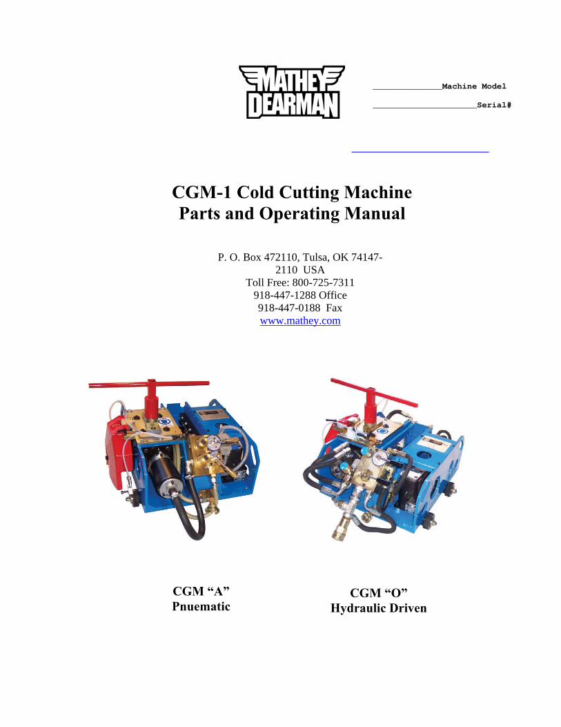
CGM “O”
Hydraulic Driven
CGM “A” Pnuematic
CGM-1 Cold Cutting Machine Parts and Operating Manual
______________Machine Model _____________________Serial#
P. O. Box 472110, Tulsa, OK 74147-2110 USA
Toll Free: 800-725-7311 918-447-1288 Office 918-447-0188 Fax www.mathey.com
2
TABLE OF CONTENTS PAGE
1. General information 3 • 1.1 – Warranty 3 • Warranty Certificate 4
2. Specifications 5 3. Accessories 6
• Figure 1 – Guide to Setting the Machine on the Pipe 7 • Figure 2 – Position of Wheels and Chain Length for Various Pipe Diameters 8
4. Safety Devices 8 • 4.1 – Accident Prevention Rules 8
5. Operating Instructions 9 • 5.1 – Connections and Power Source 9 • 5.2 – Setting Wheels for the Pipe Diameter to be Cut 10 • 5.3 – How to Lengthen and Shorten the Chain 10 • 5.4 – Getting Started 12 • 5.5 – Installation of the CGM on the pipe 12 • 5.6 – Installation of the Center and Beveling Cutter 13
6. Cutting Process 15 • 6.1 – Preparation for the Cutting Process 15 • 6.2 – Using the Machine in the cutting Process 16
7. Disconnecting the Power Source 17 8. Disassembly after Use 17 9. Maintenance 18
• 9.1 – Routine Maintenance 18 • 9.2 – Manufacturers of Hydraulic Oil and Viscosity Index 19 • 9.3 – Viscosity to Temperature Ratio 19 • 9.4 – Extraordinary Maintenance 20 • 9.5 – Lubrication Guide for CGM-1 “A” and “O” 20 • 9.6 – Troubleshooting Guide 21 • 9.7 – Troubleshooting Guide (continued) 22
10. Use Condition 23 • 10.1 Provided Use Condition 23 • 10.2 Use Not Allowed 23
11. Conformity of the Machine 23 12. Drawings and Parts list 25
• Drawing 1 – CGM Body 25 • Table 1 – CGM Body Part 1 (Items 19 – 88) 26 • Table 1 – CGM Body Part 2 (Items 89 – 129A) 27 • Table 1 – CGM Body Part 3 (Items 131A – 428) 28 • Drawing 2 – CGM Transmission 29 • Table 2 – CGM Transmission Part 1 (Items 1 – 29) 30 • Table 2 – CGM Transmission Part 2 (Items 30 – 139) 31 • Drawing 3 – Pneumatic Start/Stop Directional Control 32 • Table 3 – Pneumatic Start/Stop Directional Control 33 • Drawing 4 – Hydraulic Start/Stop Directional Control 34 • Table 4 – Hydraulic Start/Stop Directional Control 35 • Drawing 5 – Pneumatic Blade Shut-off System 36 • Table 5 – Pneumatic Blade Shut-off System 36 • Drawing 6 – Hydraulic Blade Shut-off System 37 • Table 6 – Hydraulic Blade Shut-off System 37 • Drawing 7 – Manual Blade Lubrication System 38 • Table 7 – Manual Blade Lubrication System 38 • Drawing 8 – Tool Kit 39 • Table 8 – Tool Kit 40 • Drawing 9 – Optional Automatic Blade Lubrication System 41 • Table 9 – Optional Automatic Blade Lubrication System 41 • Drawing 10 – Pneumatic and Hydraulic Hoses 42 • Table 10 – Pneumatic and Hydraulic Hoses 42 • Drawing 11 – Air Filter / Pressure Regulator / Oiler 43 • Table 11 – Air Filter / Pressure Regulator / Oiler 44
13. Warranty 44
3
a. GENERAL INFORMATION This Parts and Operating Manual is a guide for the use and maintenance of the PNEUMATIC MODEL CGM-1 “A” PIPE CUTTING BEVELING MACHINE and HYDRAULIC MODEL CGM-1 “O” PIPE CUTTING BEVELLING MACHINE made by:
C.I.A. MATHEY ITALIANA S.r.l. VIA ISONZO 26-20050 S. DAMIANO di BRUGHERIO-MILANO
Phone: 39039-831019 or 39039-2020021 Fax: 39039-2020079
This Parts and Operating Manual is supplied with the machine and placed in the steel carrying case at the time of shipment. A copy of the Parts and Operating Manual can also be obtained on the internet at www.mathey.com. The manual should be read and understood by all operators prior to attempting the operation of the CGM-1. The manual should be stored in a dust and humidity free environment that is easily accessible to the operator for consultation. Maintenance personnel and purchasing staff should consult the manual prior to attempting any maintenance of ordering spare part or for any questions concerning Warranty.
Please have the following information available when requesting a manual: • Type of Machine • Production Number • Supplier • Customer Name and Address • Address to Deliver the Copy of the Manual This Manual reflects that the CGM-1 and/or manual is “The State of The Art” at the moment of sale and it can not be considered inadequate if the unit has been updated due to new technology. The producer is not obligated to update the manuals of previously sold machine, if due to new advances in technology and if the machine is modified and/or improved. Please inform Producer of any changes in order to provide the new owner with up to date information if the machine has been altered by anyone other than the manufacturer. Please contact C.I.A. MATHEY ITALIANA S.r.l. or MATHEY DEARMAN, INC. with any suggestions on how to improve the equipment or its performance.
1.1 WARRANTY C.I.A. Mathey Italiana S.r.l. warrants the product mentioned in this manual for a period of one (1) year with the date of deliver. This warranty will only be valid if the company receives the Warranty Form with all sections completed; C.I.A. Mathey Italiana S.r.l. or Mathey Dearman will return the form with an authorized signature. The Warranty is valid only for the above-mentioned period and only for the parts that have defect of design or material. The Warranty Complaint, with a full explanation of the defect, must be sent to C.I.A. Mathey Italiana S.r.l. or Mathey Dearman, Inc. will provide full instructions for the repair or replacement of the defective parts free of charge.
C.I.A. Mathey S.r.l. is not and will not be responsible for the following: • Improper use of the machine other than its intended use. • A use against the national and/or international regulations in force. • Improper installation. • Wrong hydraulic or air connections. • Improper or incorrect maintenance of CGM-1 or Power Supply. • Unauthorized modifications and/or services. • Substitution of parts or components that are not original spare-parts or specific components recommended by C.I.A.
Mathey Italiana or Mathey Dearman, Inc. • Non-observance or partial observance of the operating instructions. • Unusual events such as natural disaster or similar events that are beyond producer’s control.
4
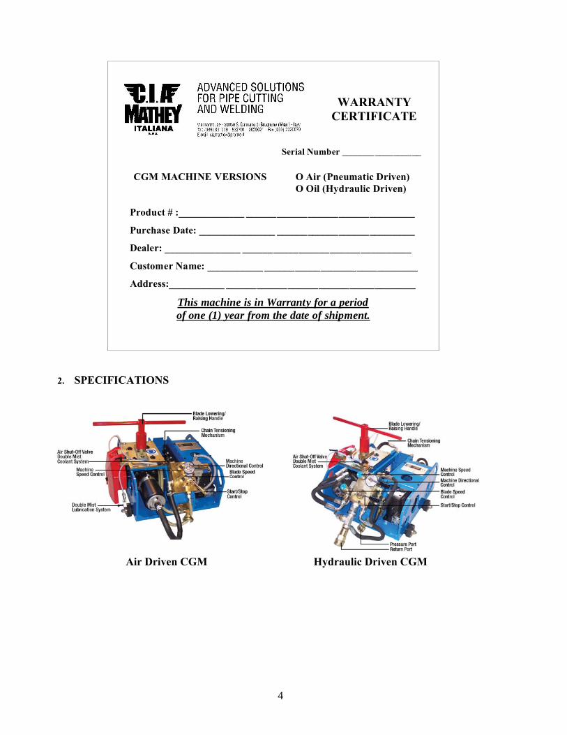
2. SPECIFICATIONS
Air Driven CGM Hydraulic Driven CGM
Serial Number _________________
CGM MACHINE VERSIONS O Air (Pneumatic Driven) O Oil (Hydraulic Driven)
Product # :_____________ _________________________________
Purchase Date: _______________ ___________________________
Dealer: _______________ _________________________________
Customer Name: ___________ ______________________________
Address:___________ _____________________________________ This machine is in Warranty for a period of one (1) year from the date of shipment.
WARRANTY
CERTIFICATE
5
The CGM pipe cutting and beveling machine is provided with two (2) motors: the first is for rotation of the cutting and beveling blades and the second motor is for rotating the machine around the pipe.
FORWARD MOTOR POWER: • Air Motor Drive Version .56 KW / .75 HP • Oil Motor Drive Version 4 KW / 5.4HP Both have a heavy reduction device (rate 400.1). FORWARD SPEED: • Air System is adjustable from 0 – 38mm / 0 – 1-1/2” per minute • Oil System is adjustable from 0 – 65mm / 0 – 2-6/16” per minute CUTTER MOTOR POWER: • Air Motor Drive Version 2,7 KW / 3.7 HP • Oil Motor Drive Version 4,0 KW 5.4 HP CUTTING PERFORMANCES: This machine cuts pipe having a minimum nominal diameter of 6 inches (152 mm.) to diameters over 72 inches (1829 mm.) by varying the 4-mesh chain length to accommodate the pipe diameter. Special Wheels are required for 6” pipe. CUTTER SPEED: • Air System is adjustable from 20 to 71 rpm. • Oil System is adjustable from 20 to 76 rpm. AIR OR HYDRAULIC POWER REQUIRED Air Driven CGM requires a compressor having a minimum capacity of about 4000 liters with a working pressure of 8 bars; connection is made by a 12.7mm (1/2 inch) tube with quick disconnect.
Hydraulic Driven CGM requires a Hydraulic Power Supply having the capability of a minimum pressure of 100 bars at 72 L/min. The Hydraulic Power Supply should have a 25 Micron Filter, Air Cooled Heat Exchanger to cool the Hydraulic Oil prior to its returning to a 200 - 250 Liter Hydraulic Reservoir. The pressure connection to the CGM-1 Machine is 12.7mm (1/2 inch) and the return connection is 19mm (3/4 inch) outlet.
CUTTER-WORK SPEED: The pipe diameter, wall thickness, beveling blade configuration, cutter wear and material hardness are determining factors in how long it will take to cut the pipe.
CLEARANCE: Depending on pipe diameter, clearance could be from 30 to 40 cm (approx. 12” - 16”) radial.
DESCRIPTION SHIPPING WEIGHT
• Air Motor Drive Version 216kg / 476lbs. • Oil Motor Drive Version 223kg / 492lbs.
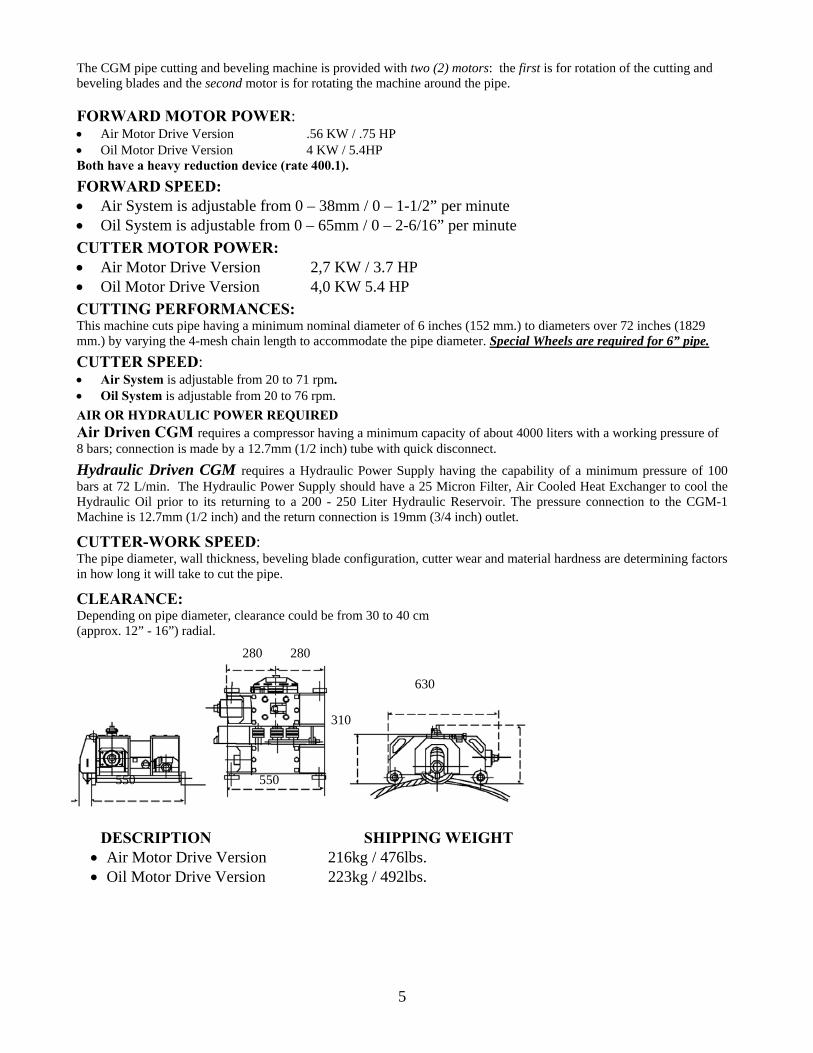
630
350
310
280 280
550 550
6
CONTROLS: Two (2) separate Speed Control Valves are provided for the cutter rotation and direction. The Speed Controls are separated for independent speed regulation of the Cutter and Machine Forward Speed. The first (lower) Speed Control Valve governs the speed of the Cutter and the second (upper) Control Valve governs the Forwarding Motor Speed. The upper “Forward-Stop-Backward” Control Lever controls the direction of the machine, around the pipe, while the Lower Control Lever provides air or hydraulic power to the Cutting and Beveling Blades and Forwarding Motor. • Air Motor Drive Version has the Air Exhaust. • Oil Motor Drive Version has Closed Hydraulic Circuit.
STORAGE DEVICES: For ease of transport, the machine comes with Steel Storage Case to protect the CGM-1 Machine, Cutting and Beveling Blades and other accessories. It is painted with polyester resins for strong environmental protection or heavy working conditions.
The Chain Driven Cold Cutting and Beveling Machine comes with: • Chain Extractor Block with Pin Extractor for segmenting chain. • Lifting Cable with Spring Clips for lifting and lowering the machine on or off the pipe. • Manual Blade Lubrication System • Blade Blanks used when only severing of the pipe is needed • 4-Mesh Chain Connecting Link and Chain Pin, adapt chain to various diameters of pipe. • Quick Disconnects for quick and easy connection of the machine to Power Supply Unit. • “T” Handle for Blade Lowering/Raising Handle of the Cutting Blade to control depth of cut. • Wedges to keep the cut open during the final operation. • Blade Wrench. • Elbow Wrench with Bayonet. • Socket for Chain Tension Nut. • Torque Wrench to set the tension of the chain. • Hex Bit Impact Socket for installing the wheels in different positions. • Parts and Operating Manual. • Rugged Steel Storage Case
3. ACCESSORIES The following accessories can be purchased for the CGM-1 “A” or “O” Machines: • Air or Hydraulic Hoses. • Center Cutters • Right and Left Beveling Cutters for 30°, 37 1/2°, compound bevels and “J” • Air Pressure Regulator with Condensation Extractor System and Lubricator for proper air treatment and pressure
regulation. • Automatic Double Mist Blade Lubrication System. • Air Compressor for Automatic Double Mist Blade Lubrication System. • Groove Wheel for Guide Track Applications. • Guide Tracks for pipes with an inclined angle up to 45° or for high precision cutting when required. • 4-Mesh Chain for cutting diameters 8” (203mm) and up. • Special Wheels required for 6” pipe. • Hand Oiler • Chip brush • Synthetic Coolant
7
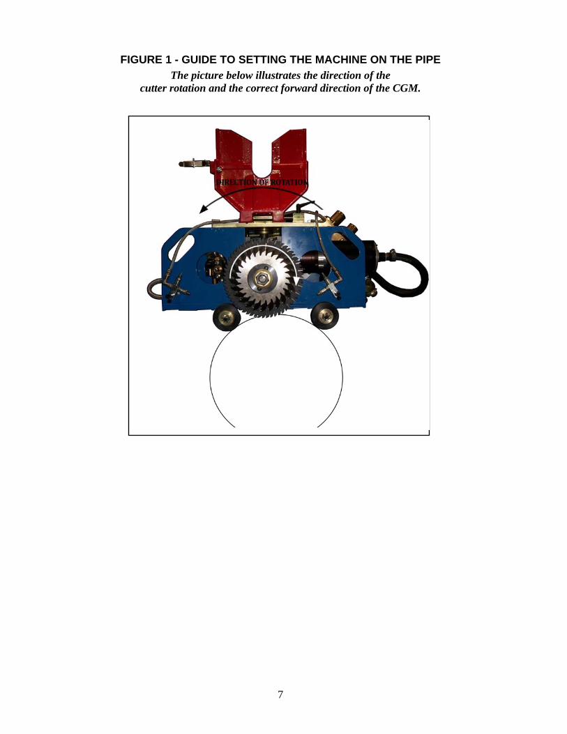
FIGURE 1 - GUIDE TO SETTING THE MACHINE ON THE PIPE The picture below illustrates the direction of the
cutter rotation and the correct forward direction of the CGM.
8
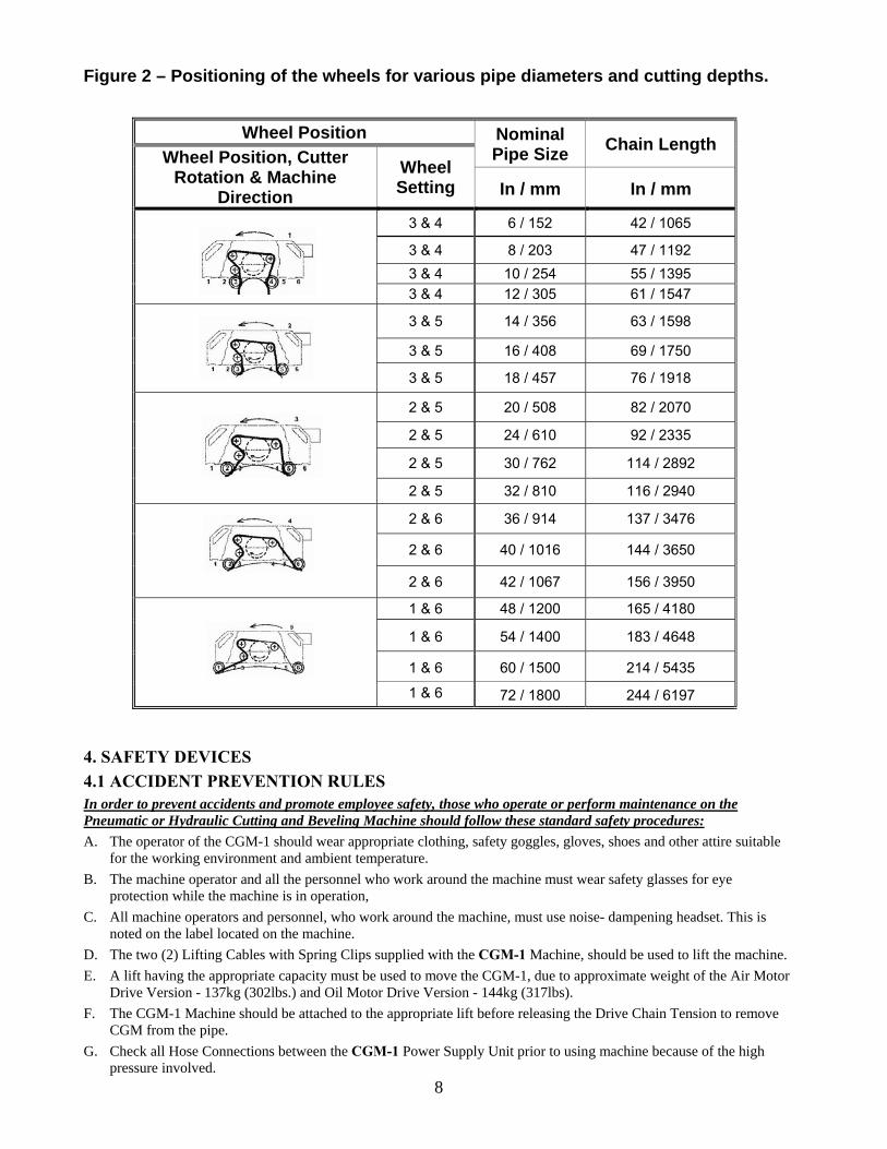
Figure 2 – Positioning of the wheels for various pipe diameters and cutting depths. 4. SAFETY DEVICES 4.1 ACCIDENT PREVENTION RULES In order to prevent accidents and promote employee safety, those who operate or perform maintenance on the Pneumatic or Hydraulic Cutting and Beveling Machine should follow these standard safety procedures: A. The operator of the CGM-1 should wear appropriate clothing, safety goggles, gloves, shoes and other attire suitable
for the working environment and ambient temperature. B. The machine operator and all the personnel who work around the machine must wear safety glasses for eye
protection while the machine is in operation, C. All machine operators and personnel, who work around the machine, must use noise- dampening headset. This is
noted on the label located on the machine. D. The two (2) Lifting Cables with Spring Clips supplied with the CGM-1 Machine, should be used to lift the machine. E. A lift having the appropriate capacity must be used to move the CGM-1, due to approximate weight of the Air Motor
Drive Version - 137kg (302lbs.) and Oil Motor Drive Version - 144kg (317lbs). F. The CGM-1 Machine should be attached to the appropriate lift before releasing the Drive Chain Tension to remove
CGM from the pipe. G. Check all Hose Connections between the CGM-1 Power Supply Unit prior to using machine because of the high
pressure involved.
Wheel Position Nominal Pipe Size Chain Length
Wheel Position, Cutter Rotation & Machine
Direction Wheel Setting In / mm In / mm
3 & 4 6 / 152 42 / 1065
3 & 4 8 / 203 47 / 1192 3 & 4 10 / 254 55 / 1395 3 & 4 12 / 305 61 / 1547
3 & 5 14 / 356 63 / 1598
3 & 5 16 / 408 69 / 1750
3 & 5 18 / 457 76 / 1918
2 & 5 20 / 508 82 / 2070
2 & 5 24 / 610 92 / 2335
2 & 5 30 / 762 114 / 2892
2 & 5 32 / 810 116 / 2940 2 & 6 36 / 914 137 / 3476
2 & 6 40 / 1016 144 / 3650
2 & 6 42 / 1067 156 / 3950
1 & 6 48 / 1200 165 / 4180
1 & 6 54 / 1400 183 / 4648
1 & 6 60 / 1500 214 / 5435
1 & 6 72 / 1800 244 / 6197
9
H. Inspect the Center and Beveling Cutters for broken teeth or cracks that might eventually cause blade breakage when machine is stopped. Always use sharp cutters for optimal machine performance.
I. For operator safety the Blade Guard should always be closed when the Cutters are rotating. J. When the machine is in operation, personnel not involved in the machine operation must stay at a safety distance or
wear the necessary safety equipment. K. The CGM-1 operator should always be in close proximity to the machine when the machine is connected to a Power
Supply Unit that is in operation and the cutters are rotating for quick access to Machine Controls. L. The Air or Hydraulic Power Supply Unit must be turned off and Hose pressure released before disconnecting hoses. M. The proper machine forward speed must be selected for the specific thickness of pipe to be cut. N. Clean the cutting area with water or approved low-pressure compressed air and avoid cleaning the cutting area
manually using wrong tools that may catch in the blades. O. Check the machine for worn parts and replace them before returning the machine to its storage case. P. Schedule and perform regularly scheduled maintenance on CGM-1 to insure operator safety.
IN ADDITION TO THE ABOVE PROCEDURES, ALL SAFETY INSTRUCTIONS CONCERNING HYDRAULIC AND/OR PNEUMATIC SYSTEMS SHOULD
ALSO BE ENFORCED. ALL THE OPERATIONS MUST BE DONE UNDER THE BEST SAFETY CONDITIONS.
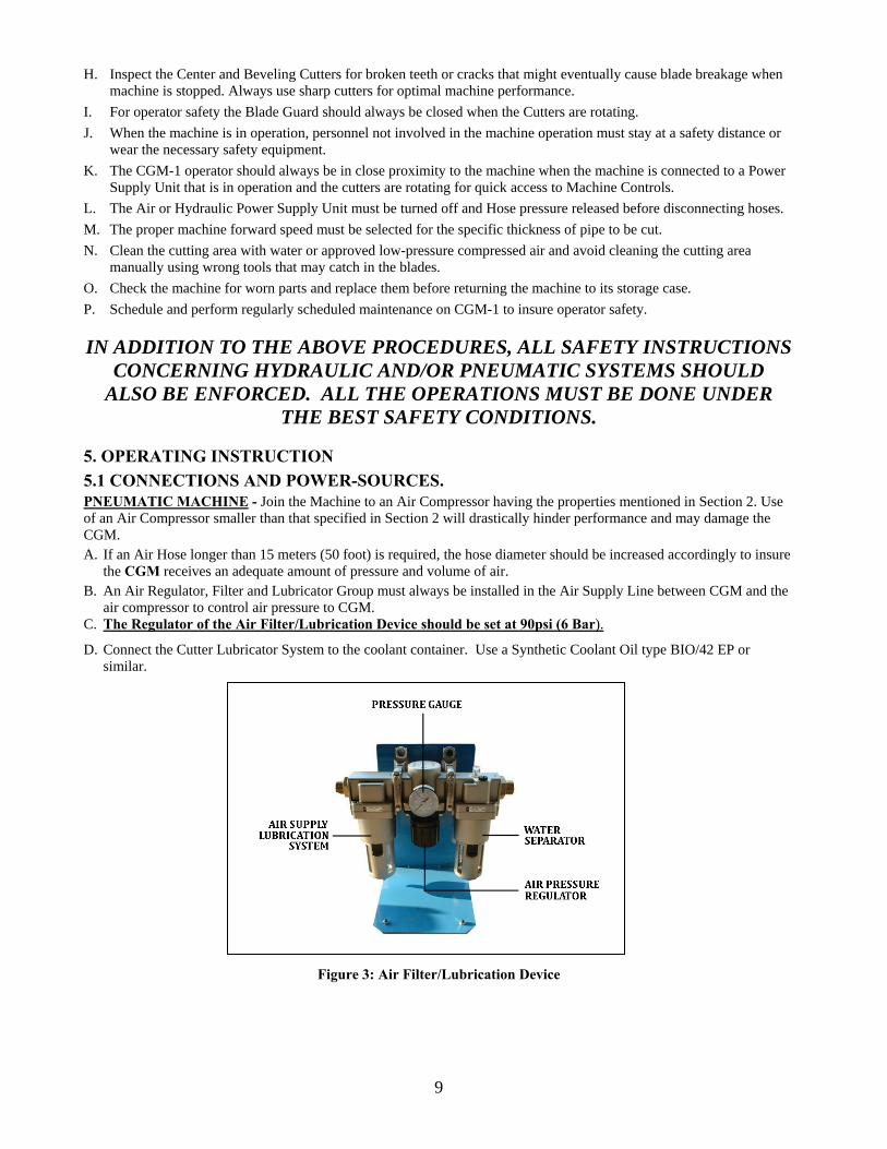
5. OPERATING INSTRUCTION 5.1 CONNECTIONS AND POWER-SOURCES. PNEUMATIC MACHINE - Join the Machine to an Air Compressor having the properties mentioned in Section 2. Use of an Air Compressor smaller than that specified in Section 2 will drastically hinder performance and may damage the CGM. A. If an Air Hose longer than 15 meters (50 foot) is required, the hose diameter should be increased accordingly to insure the CGM receives an adequate amount of pressure and volume of air. B. An Air Regulator, Filter and Lubricator Group must always be installed in the Air Supply Line between CGM and the air compressor to control air pressure to CGM. C. The Regulator of the Air Filter/Lubrication Device should be set at 90psi (6 Bar).
D. Connect the Cutter Lubricator System to the coolant container. Use a Synthetic Coolant Oil type BIO/42 EP or similar.
Figure 3: Air Filter/Lubrication Device
10
HYDRAULIC MACHINE - Join the Machine to a Hydraulic Power Supply having the properties mentioned in Section 2. The Hydraulic CGM-1 is powered by a closed oil circuit Hydraulic Power Supply having a 1/2" pressure (outlet) port and 3/4" return (inlet) port. The use of a Hydraulic Power Supply smaller than that specified in Section 2 will significantly hinder performance and may damage the CGM. A. If Hydraulic Hoses longer than 15 meters (50 foot) are required, the hose diameters should be increased accordingly
to insure the CGM receives an adequate hydraulic flow and pressure. B. Check the rotation of the Cutter Blades to insure the Hydraulic Power Supply is connected to the CGM-1 properly.
The rotation of the Cutter Blades is clockwise as shown in Figure 1. C. The Hydraulic Model CGM-1 requires a small air compressor to operate the Automatic Double Mist Lubrication
System if installed. D. Connect the Double Mist Lubrication System to the Coolant Container. Use a synthetic coolant oil type BIO/42 EP
or similar is recommended. E. Turn the “Start / Stop Control” to the ON Position. F. Slowly open Blade Speed Control counterclockwise until the rotational speed reaches about
71 – 76 revolutions per minute. Check the rotation of the Severing and Beveling Blades to make sure they are turning clockwise.
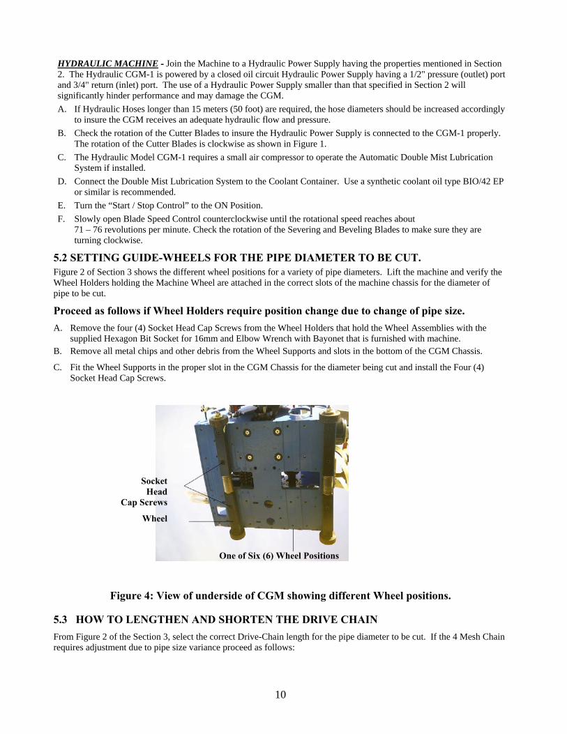
5.2 SETTING GUIDE-WHEELS FOR THE PIPE DIAMETER TO BE CUT. Figure 2 of Section 3 shows the different wheel positions for a variety of pipe diameters. Lift the machine and verify the Wheel Holders holding the Machine Wheel are attached in the correct slots of the machine chassis for the diameter of pipe to be cut.
Proceed as follows if Wheel Holders require position change due to change of pipe size. A. Remove the four (4) Socket Head Cap Screws from the Wheel Holders that hold the Wheel Assemblies with the
supplied Hexagon Bit Socket for 16mm and Elbow Wrench with Bayonet that is furnished with machine. B. Remove all metal chips and other debris from the Wheel Supports and slots in the bottom of the CGM Chassis.
C. Fit the Wheel Supports in the proper slot in the CGM Chassis for the diameter being cut and install the Four (4) Socket Head Cap Screws.
Figure 4: View of underside of CGM showing different Wheel positions.
5.3 HOW TO LENGTHEN AND SHORTEN THE DRIVE CHAIN From Figure 2 of the Section 3, select the correct Drive-Chain length for the pipe diameter to be cut. If the 4 Mesh Chain requires adjustment due to pipe size variance proceed as follows:
Socket Head
Cap Screws
Wheel
One of Six (6) Wheel Positions
11
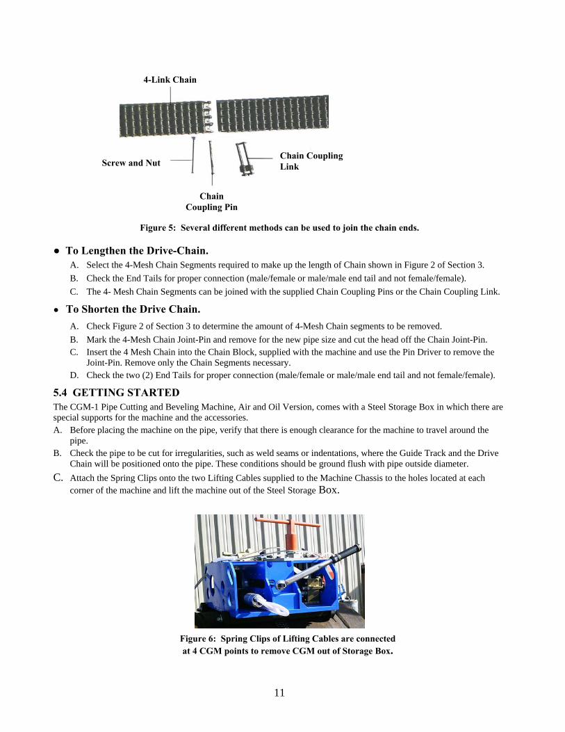
Figure 5: Several different methods can be used to join the chain ends.
● To Lengthen the Drive-Chain. A. Select the 4-Mesh Chain Segments required to make up the length of Chain shown in Figure 2 of Section 3. B. Check the End Tails for proper connection (male/female or male/male end tail and not female/female). C. The 4- Mesh Chain Segments can be joined with the supplied Chain Coupling Pins or the Chain Coupling Link.
● To Shorten the Drive Chain. A. Check Figure 2 of Section 3 to determine the amount of 4-Mesh Chain segments to be removed. B. Mark the 4-Mesh Chain Joint-Pin and remove for the new pipe size and cut the head off the Chain Joint-Pin. C. Insert the 4 Mesh Chain into the Chain Block, supplied with the machine and use the Pin Driver to remove the
Joint-Pin. Remove only the Chain Segments necessary. D. Check the two (2) End Tails for proper connection (male/female or male/male end tail and not female/female).
5.4 GETTING STARTED The CGM-1 Pipe Cutting and Beveling Machine, Air and Oil Version, comes with a Steel Storage Box in which there are special supports for the machine and the accessories. A. Before placing the machine on the pipe, verify that there is enough clearance for the machine to travel around the
pipe. B. Check the pipe to be cut for irregularities, such as weld seams or indentations, where the Guide Track and the Drive
Chain will be positioned onto the pipe. These conditions should be ground flush with pipe outside diameter. C. Attach the Spring Clips onto the two Lifting Cables supplied to the Machine Chassis to the holes located at each
corner of the machine and lift the machine out of the Steel Storage Box.
Figure 6: Spring Clips of Lifting Cables are connected at 4 CGM points to remove CGM out of Storage Box.
Chain Coupling Link Screw and Nut
Chain Coupling Pin
4-Link Chain
12
D. Once the machine is lifted to a comfortable height, fit the Drive Chain on to the Sprockets of the Machine as shown in Figure 2 for the pipe diameter that is to be cut, leaving the Tail Ends of the Chain free. E. Check the Tail Ends of the Chain to make sure they can be linked.
5.5 INSTALLATION OF THE CGM ON THE PIPE
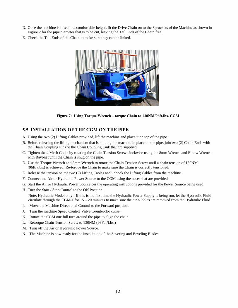
A. Using the two (2) Lifting Cables provided, lift the machine and place it on top of the pipe. B. Before releasing the lifting mechanism that is holding the machine in place on the pipe, join two (2) Chain Ends with the Chain Coupling Pins or the Chain Coupling Link that are supplied. C. Tighten the 4 Mesh Chain by rotating the Chain Tension Screw clockwise using the 8mm Wrench and Elbow Wrench with Bayonet until the Chain is snug on the pipe. D. Use the Torque Wrench and 8mm Wrench to rotate the Chain Tension Screw until a chain tension of 130NM (96ft. /lbs.) is achieved. Re-torque the Chain to make sure the Chain is correctly tensioned. E. Release the tension on the two (2) Lifting Cables and unhook the Lifting Cables from the machine. F. Connect the Air or Hydraulic Power Source to the CGM using the hoses that are provided. G. Start the Air or Hydraulic Power Source per the operating instructions provided for the Power Source being used. H. Turn the Start / Stop Control to the ON Position. Note: Hydraulic Model only - If this is the first time the Hydraulic Power Supply is being run, let the Hydraulic Fluid circulate through the CGM-1 for 15 – 20 minutes to make sure the air bubbles are removed from the Hydraulic Fluid. I. Move the Machine Directional Control to the Forward position. J. Turn the machine Speed Control Valve Counterclockwise. K. Rotate the CGM one full turn around the pipe to align the chain. L. Retorque Chain Tension Screw to 130NM (96Ft. /Lbs.) M. Turn off the Air or Hydraulic Power Source. N. The Machine is now ready for the installation of the Severing and Beveling Blades.
Figure 7: Using Torque Wrench – torque Chain to 130NM/96ft.lbs. CGM
13
5.6 INSTALLATION OF THE CENTER AND BEVELING CUTTERS. A. With the Column Tensioning Wrench provided, loosen the four (4) Column Locking Screws that hold the Blade
Transmission steadfast to the column.
B. Figure 8: Column Tensioning Wrench
C. Figure 9: Front Column Lock Screws
D. Figure 10: Rear Column Lock Screws
Column Tensioning Screw
Column Tensioning Screw
14
B. With the aid of the Blade Lowering/Raising Handle, turn the Feed Screw clockwise until the Cutter Spindle (See Figure 13) is raised to its highest position to avoid the Cutters touching the pipe during installation or removal.
C. Remove the Cutter Lock Nut by rotating it clockwise using the 32mm Wrench furnished with the machine.
D. Remove the Cutter Lock Nut, Washer and Cutter Support Collar. (Refer to Figure 13.)
Figure 12: Side View Blades E. Remove any metal chips and other debris from the Cutter Spindle, Male Cutter Drive Collar, Female Cutter Drive
Collar and Cutter Lock Nut (Refer to Figure 13).
Figure 13: Cutter Drive Assembly
15
F. Remove any metal chips from the Cutting and Beveling Blades. G. Place the Bevel Cutter on the Cutter Spindle so that the cutting edge is facing downward (Refer to Figure 12). H. Align the holes in the Bevel Cutter with the two (2) Hardened Pins and push the Bevel Cutter forward, until it
contacts the face of the Male Cutter Drive Collar. Note: The Center and Beveling Cutters will fit snuggly on the Shaft. (Refer to Figure 13).
I. Follow the same procedure to install the Center Cutter and the second Beveling Cutter. J. Install the Cutter Support Collar, Washer and Cutter Lock Nut. (Refer to Figure 13). K. Tighten the Cutter Lock Nut counterclockwise using 32mm Wrench. L. Lower the Cutter Safety Cover and latch the Blade Safety Device to the Cover.
Note: The machine will not function if Blade Safety Cover is not latched to the Blade Safety Device. Note: Never operate the machine with the Severing Blade and only one Beveling Cutter.
Note: Never use the Severing Blade to sever the pipe without the Severing Blade Space for each side of the blade. Note: Never use the two (2) Beveling Cutters without the Center Cutter.
6 CUTTING PROCESS. 6.1 PREPARATION FOR THE CUTTING PROCESS
Figure 14: Air Regulator Group
Figure 15: Hydraulic Regulator Group
A. With the Blade Lowering / Raising Handle, turn the Feed Screw until the Cutter Spindle is raised to its highest position.
B. Turn the Start / Stop Control to the OFF Position. C. Turn the Machine Directional Control to the STOP Position. D. Turn the Machine Speed Control clockwise to the “0” position or fully closed position. E. Turn the Blade Speed Control clockwise to the “0” position or fully closed position.
Machine Speed Control
Blade Speed Control
Machine Directional Control
Start/Stop Control
Machine Speed Control
Blade Speed Control
Machine Directional Control
Start/Stop Control
16
F. Check the Safety Cutter Cover to insure it is closed and the Latch of the Blade Shut-off Device is latched to the Cover.
G. Turn off the Air or Hydraulic Power Source and bleed the air or hydraulic pressure from the supply hoses. H. Safety Warning: Do not connect Hydraulic Hoses that are under pressure as it may result in serious injury. I. Connect and secure the Air or Hydraulic Hose Quick Disconnects to the CGM-1. J. Safety Warning: Insure that the Air or Hydraulic Hose Quick Disconnects are attached properly and are secure as it
may cause serious injury.
NOTE: Air Filter/Lubrication Device must be placed in the center of the two (2) Air Hoses. Make sure the bowl of the Lubricator Assembly is filled with Pneumatic Oil.
K. Start the Air or Hydraulic Power Supply per the manufacturer’s instructions. Safety Warning: When Air or Hydraulic Power is applied the CGM-1, an operator should be within easy reach of the CGM Controls and the Controls of the Air or Hydraulic Power Supply at all times.
L. Verify the source of Air or Hydraulic power minimum output pressure and flow rate of:
Model Pressure Rate Air Machine 8 bar (120psi) 4000 l. /min / 142cfm
Hydraulic Machine 100 bar (1,420psi) 72 l. /min / 20gpm Warning: Air Model – Adjust air pressure at the Air Filter/Lubrication Device is set at 6 Bar (90psi) using the Pressure Regulator Valve. Failure to do so will cause damage to the Blade and Drive Motors.
Hydraulic Model – Make sure the relief valve of the Hydraulic Power Supply is set at 110 bar (1,420psi). Failure to do so will cause damage to the Blade and Drive Motors.
6.2 USING THE MACHINE IN THE CUTTING PROCESS. The Machine Chassis has six (6) slots that are machined into the bottom of the Chassis to make up five (5)-wheel settings to center the Cutting Blades on the pipe. Proper positioning of the Wheel Holders gives the machine the optimal stability, tracking and cutting performance. The Drive Chain must be the right length for the diameter of pipe to be cut. Figure 2 of Section 3 shows the different wheel positions and chain lengths for most common diameters of pipe.
Note: Refer to the Trouble Shooting Chart in the back of this manual if the Blades are not rotating.
Note: Hydraulic Model only - If this is the first time the Hydraulic Power Supply is being run, let the hydraulic fluid circulate through the CGM-1 for 15 – 20 minutes to make sure the air bubbles are removed from the hydraulic fluid.
A. Turn the Air Valve of the Cutter Lubrication Device to the ON Position. B. Adjust the Lubricator Nozzle as needed to provide a steady flow of coolant on the Blades.
Note: If there is no flow of coolant from the Lubricator Nozzle refer to the Trouble Shooting Chart in the back of this manual.
C. With the Blade Lowering / Raising Crank, turn the Feed Screw counterclockwise until the Cutters are through the thickness of the pipe at desired depth.
D. Remove the Blade Lowering / Raising Crank from the Feed Screw and with the Column Tensioning Wrench provided, tighten the 4 Hex Head Cap Screws that hold Blade Transmission securely to the 4 columns.
E. Turn the Machine Directional Control to the FORWARD Position. Note: Never attempt to cut the pipe by placing the Forward Control Knob in the REVERSE Position.
F. Slowly open the Forward Speed Regulator Valve until the desired forward speed is achieved. G. Check the pipe to see if the desired cut and bevel depth and cut finish are being achieved. H. Cutter Stoppage:
I. If a Cutter Block occurs, quickly turn the Machine Directional Control to the REVERSE Position and leave it in that position until the Cutters start to rotate.
II. When the Cutters start rotating - move the Machine Directional Control to the STOP Position. III. Close the Forward Speed Regulator Valve a small amount. IV. Turn the Machine Directional Control to the FORWARD Position.
Note: The operator should observe the cut at all times and should insert the appropriate wedges as needed during the final stages of the cut to maintain the cut opening to avoid Cutter Blade stoppage or breakage.
17
I. When the cut is finished, move the Machine Directional Control to the STOP Position. J. Loosen the 4 Hex Head Cap Screws that hold the Blade Transmission securely to the 4 columns; using the Blade
Lowering / Raising Handle rotate the Feed Screw, until the Cutter Spindle is raised to its highest position. K. Turn the Start / Stop Control to the OFF Position. L. Turn the Air Valve of the Double Mist Lubrication System to the OFF Position. M. Turn off the Air or Hydraulic Power Supply. N. Bleed all Air or Hydraulic pressure from the Hoses connecting the CGM-1 to the Air or Hydraulic Power
Supply. O. Disconnect the Hoses from the CGM-1.
Safety Warning:
• Due to serious risk of injury do not attempt to disconnect Hoses from the CGM-1 without bleeding the Air or Hydraulic pressure from the Hoses or turning off the Air or Hydraulic Power.
• Check for the presence of obstacles that could obstruct the forward movement of the machine around the pipe. • With the Column Tensioning Wrench provided, loosen the 4 Hex Head Cap Screws that hold the Blade
Transmission steadfast to the 4 columns. 7 DISCONNECTING THE POWER SOURCE. To disconnect the Power Source and stop the use of all the equipment, proceed as follows:
• FOR PNEUMATIC MOTOR DRIVE MACHINE A. Turn off the air supply. B. Bleed all air pressure from the Hose connecting the CGM-1 to the air supply by rotating the Cutter Control Knob
back and forward to the OFF and ON Position several times. C. Disconnect the Air Hose from the CGM-1.
Safety Warning: Due to the risk of injury do not attempt to disconnect Hoses from the CGM-1 without bleeding the Air or Hydraulic Pressure from the Hoses or turning off the Air or Hydraulic Power Supply.
• FOR HYDRAULIC MOTOR DRIVE MACHINE A. Turn off the Hydraulic Power Supply. B. Bleed all Hydraulic Pressure from the Hoses connecting the CGM-1 to the Hydraulic Power Supply by rotating
the Cutter Control Knob back and forward to the OFF and ON Position several times. C. Disconnect the Hoses from the CGM.
Safety Warning: Do not attempt to disconnect Hoses from the CGM without bleeding the Air or Hydraulic pressure from the hoses or turning off the Air or Hydraulic Power Supply as it may result in serious injury.
8 DISASSEMBLY AFTER USE Remove the machine as follows when the cutting process is finished as follows: A. Disconnect the Power Source as described in section 7. B. Disengage the Safety Device Latch and lift up the Safety Cutter Cover. C. Rotate and remove the Lock Nut counterclockwise using 32mm Wrench, then remove the Female Cutter Drive
Collar. D. Remove all Cutter Blades from the Cutter Spindle.
Note: If Cutters are not removed, prior to lifting the machine, they may be damaged during the lifting process.
E. Inspect the Cutter Blades for wear, chipped and damaged teeth. Report any irregularity to the responsible manager so that the Blades can be re-sharpened.
F. Connect the two (2) Lifting Cables to the holes in the four (4) corners of the CGM Body. G. Apply tension to the two (2) Lifting Cables with a Lift or Crane. H. Release tension on the 4-Mesh Chain by rotating the Chain Tension Screw using the 8mm Wrench and Elbow
Wrench with Bayonet counterclockwise. I. Remove the Chain Coupling Pins or the Chain Coupling Link from the 4-Mesh Chain Ends. J. Lift the CGM-1 off the pipe.
18
K. Remove all chips and other debris from the machine with a brush and water or air pressure.
L. Check all nut, bolts and fittings for tightness.
M. Spray a light film of oil on the CGM-1.
N. Place the CGM-1 in its Storage Box.
O. Store the Machine in sheltered area to avoid damage.
9. MAINTENANCE 9.1 ROUTINE MAINTENANCE Plan all routine maintenance to the CGM-1 when the machine is not in operation. When the machine is cutting “heavy wall pipe or high strength alloy pipes”, it is recommended the machine be thoroughly checked after each cut.
GENERAL – A. Inspect the Cutter Blades for wear, chipped, damaged teeth and the integrity of the cutting after each cut. B. Check the tightness of all nuts, bolts, screws and fittings at the end of each day of operation, C. If applicable check the Double Mist Lubrication System on a regular basis during the cutting process make sure both
sides of the system are working properly. After each use check the Nozzles for obstruction and clean as required. Always keep the synthetic coolant plastic bottle clean to avoid debris or dirt that may obstruct the Injection Nozzle.
PNEUMATIC MACHINE - A. Check the Air Filter / Lubrication Device and periodically check the assembly to be certain it is functioning properly
when using the Air Drive CGM. Drain the water from the water separator of the Air Filter / Lubrication Device on a regulator basis. Replenish the oil in the inline Lubricator of the Air Filter / Lubrication Device with pneumatic oil as needed.
B. Periodic checks should be performed on the Air or Hydraulic Power Supply as required by the manufacturer to insure that the CGM will function properly. Report any irregularities to the responsible manager.
HYDRAULIC MACHINE – In order to obtain the best performance from the CGM-1, it is important to choose a hydraulic fluid with the best viscosity index for the ambient temperature the CGM will be working. To get the best performance out of the CGM, especially under extreme cutting conditions, with variations in temperature, use synthetic additive oil with a high degree of stability. For applications with vegetable biodegradable oil and special mixture (i.e.: glycol-water) contact Mathey Dearman, Inc. and/or C.I.A. Mathey’s technical department. A. When adding hydraulic fluid to the Reservoir of the Hydraulic Power Supply, filter the oil through a 25 micro filter.
Note: Failure to do filter the fluid may cause damage to the hydraulic blade and forward motors. B. When adding hydraulic fluid to the Hydraulic Power Supply, use the same manufacturer of the hydraulic oil that
was originally in the reservoir. WARNING: • Never run the CGM with a Hydraulic Power Supply that does not have a minimum of a 25 micro filtration system. • Do not mix various manufacturers’ hydraulic and viscosity fluid together. • Do not mix Hydraulic Oil or use varying viscosities fail due to the impacting of the machine performance and may
cause damage to the CGM-1 “O”. C. Never use reprocessed hydraulic fluids. D. Never disperse hydraulic fluid into the environment.
19
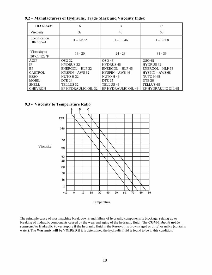
9.2 – Manufacturers of Hydraulic, Trade Mark and Viscosity Index
DIAGRAM A B C
Viscosity 32 46 68
Specification DIN 51524 H – LP 32 H – LP 46 H – LP 68
Viscosity to 50°C / 122°F
16 - 20 24 - 28 31 - 39
AGIP IP BP CASTROL ESSO MOBIL SHELL CHEVRON
OSO 32 HYDRUS 32 ENERGOL – HLP 32 HYSPIN – AWS 32 NUTO H 32 DTE 24 TELLUS 32 EP HYDRAULIC OIL 32
OSO 46 HYDRUS 46 ENERGOL – HLP 46 HYSPIN – AWS 46 NUTO H 46 DTE 25 TELLUS 46 EP HYDRAULIC OIL 46
OSO 68 HYDRUS 32 ENERGOL – HLP 68 HYSPIN – AWS 68 NUTO H 68 DTE 26 TELLUS 68 EP HYDRAULIC OIL 68
9.3 - Viscosity to Temperature Ratio
Temperature
The principle cause of most machine break downs and failure of hydraulic components is blockage, seizing up or breaking of hydraulic components caused by the wear and aging of the hydraulic fluid. The CGM-1 should not be connected to Hydraulic Power Supply if the hydraulic fluid in the Reservoir is brown (aged or dirty) or milky (contains water). The Warranty will be VOIDED if it is determined the hydraulic fluid is found to be in this condition.
Viscosity
20
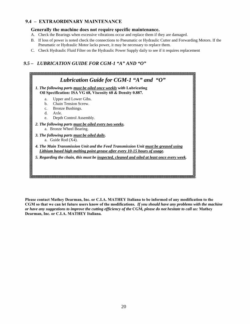
Lubrication Guide for CGM-1 “A” and “O” 1. The following parts must be oiled once weekly with Lubricating
Oil Specification: ISA VG 68, Viscosity 68 & Density 0.887. a. Upper and Lower Gibs. b. Chain Tension Screw. c. Bronze Bushings. d. Axle. e. Depth Control Assembly. 2. The following parts must be oiled every two weeks. a. Bronze Wheel Bearing. 3. The following parts must be oiled daily. a. Guide Rod (X4). 4. The Main Transmission Unit and the Feed Transmission Unit must be greased using Lithium based high melting point grease after every 10-15 hours of usage. 5. Regarding the chain, this must be inspected, cleaned and oiled at least once every week.
9.4 – EXTRAORDINARY MAINTENANCE
Generally the machine does not require specific maintenance. A. Check the Bearings when excessive vibrations occur and replace them if they are damaged. B. If loss of power is noted check the connections to Pneumatic or Hydraulic Cutter and Forwarding Motors. If the
Pneumatic or Hydraulic Motor lacks power, it may be necessary to replace them. C. Check Hydraulic Fluid Filter on the Hydraulic Power Supply daily to see if it requires replacement
9.5 – LUBRICATION GUIDE FOR CGM-1 “A” AND “O”
Please contact Mathey Dearman, Inc. or C.I.A. MATHEY Italiana to be informed of any modification to the CGM so that we can let future users know of the modifications. If you should have any problems with the machine or have any suggestions to improve the cutting efficiency of the CGM, please do not hesitate to call us: Mathey Dearman, Inc. or C.I.A. MATHEY Italiana.
21
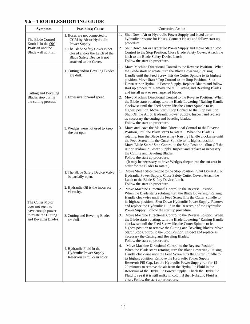
9.6 – TROUBLESHOOTING GUIDE
Symptom Possible(s) Cause Corrective Action
The Blade Control Knob is in the ON Position and the Blade will not turn.
1. Hoses are not connected to CGM by Air or Hydraulic Power Supply.
2. The Blade Safety Cover is not closed and/or the Latch of the Blade Safety Device is not attached to the Cover.
1. Shut Down Air or Hydraulic Power Supply and bleed air or hydraulic pressure for Hoses. Connect Hoses and follow start up procedure.
2. Shut Down Air or Hydraulic Power Supply and move Start / Stop Control to the Stop Position. Close Blade Safety Cover. Attach the latch to the Blade Safety Device Latch. Follow the start up procedure.
Cutting and Beveling Blades stop during the cutting process.
1. Cutting and/or Beveling Blades are dull.
2. Excessive forward speed.
3. Wedges were not used to keep the cut open
1. Move Machine Directional Control to the Reverse Position. When the Blade starts to rotate, turn the Blade Lowering / Raising Handle until the Feed Screw lifts the Cutter Spindle to its highest position. Move Start / Top Control to the Stop Position. Shut Down Air or Hydraulic Power Supply. Replace Blades and follow start up procedure. Remove the dull Cutting and Beveling Blades and install new or re-sharpened blades.
2. Move Machine Directional Control to the Reverse Position. When the Blade starts rotating, turn the Blade Lowering / Raising Handle clockwise until the Feed Screw lifts the Cutter Spindle to its highest position. Move Start / Stop Control to the Stop Position. Shut Off the Air or Hydraulic Power Supply. Inspect and replace as necessary the cutting and beveling blades. Follow the start up procedure.
3. Move and leave the Machine Directional Control to the Reverse Position, until the Blade starts to rotate. When the Blade is rotating, turn the Blade Lowering / Raising Handle clockwise until the Feed Screw lifts the Cutter Spindle to its highest position. Move Blade Start / Stop Control to the Stop Position. Shut Off the Air or Hydraulic Power Supply. Inspect and replace as necessary the Cutting and Beveling Blades. Follow the start up procedure.
(It may be necessary to drive Wedges deeper into the cut area in order for the Blades to rotate.)
The Cutter Motor does not seem to have enough power to rotate the Cutting and Beveling Blades
1. The Blade Safety Device Valve is partially open.
2. Hydraulic Oil is the incorrect viscosity.
3. Cutting and Beveling Blades are dull.
4. Hydraulic Fluid in the Hydraulic Power Supply Reservoir is milky in color
1. Move Start / Stop Control to the Stop Position. Shut Down Air or Hydraulic Power Supply. Close Safety Cutter Cover. Attach the Latch to the Blade Safety Device Latch. Follow the start up procedure.
2. Move Machine Directional Control to the Reverse Position. When the Blade starts rotating, turn the Blade Lowering / Raising Handle clockwise until the Feed Screw lifts the Cutter Spindle to its highest position. Shut Down Hydraulic Power Supply. Remove and replace the Hydraulic Fluid in the Reservoir of the Hydraulic Power Supply. Follow the start up procedure.
3. Move Machine Directional Control to the Reverse Position. When the Blade starts rotating, turn the Blade Lowering / Raising Handle clockwise until the Feed Screw lifts the Cutter Spindle to its highest position to remove the Cutting and Beveling Blades. Move Start / Stop Control to the Stop Position. Inspect and replace as necessary the Cutting and Beveling Blades. Follow the start up procedure.
4. Move Machine Directional Control to the Reverse Position. When the Blade starts rotating, turn the Blade Lowering / Raising Handle clockwise until the Feed Screw lifts the Cutter Spindle to its highest position. Remove the Hydraulic Power Supply Reservoir Fill Cap. Let the Hydraulic Power Supply run for 15 – 20 minutes to remove the air from the Hydraulic Fluid in the Reservoir of the Hydraulic Power Supply. Check the Hydraulic Fluid to see if it is still milky in color. If the Hydraulic Fluid is clear. Follow the start up procedure.
22
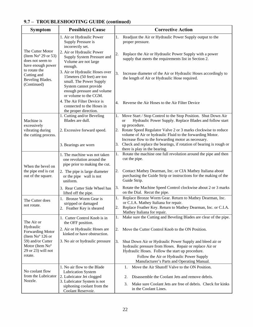
9.7 – TROUBLESHOOTING GUIDE (continued) Symptom Possible(s) Cause Corrective Action
The Cutter Motor (Item Noº 29 or 53) does not seem to have enough power to rotate the Cutting and Beveling Blades. (Continued)
1. Air or Hydraulic Power Supply Pressure is incorrectly set.
2. Air or Hydraulic Power Supply System Pressure and Volume are not large enough.
3. Air or Hydraulic Hoses over 15meters (50 feet) are too small. The Power Supply System cannot provide enough pressure and volume or volume to the CGM.
4. The Air Filter Device is connected to the Hoses in the proper direction.
1. Readjust the Air or Hydraulic Power Supply output to the proper pressure.
2. Replace the Air or Hydraulic Power Supply with a power supply that meets the requirements list in Section 2.
3. Increase diameter of the Air or Hydraulic Hoses accordingly to the length of Air or Hydraulic Hose required.
4. Reverse the Air Hoses to the Air Filter Device
Machine is excessively vibrating during the cutting process.
1. Cutting and/or Beveling Blades are dull.
2. Excessive forward speed.
3. Bearings are worn
1. Move Start / Stop Control to the Stop Position. Shut Down Air or Hydraulic Power Supply. Replace Blades and follow start up procedure.
2. Rotate Speed Regulator Valve 2 or 3 marks clockwise to reduce volume of Air or hydraulic Fluid to the forwarding Motor. Increase flow to the forwarding motor as necessary.
3. Check and replace the bearings, if rotation of bearing is rough or there is play in the bearing.
When the bevel on the pipe end is cut out of the square.
1. The machine was not taken one revolution around the pipe prior to making the cut.
2. The pipe is large diameter or the pipe wall is not uniform.
3. Rear Cutter Side Wheel has lifted off the pipe.
1. Rotate the machine one full revolution around the pipe and then cut the pipe.
2. Contact Mathey Dearman, Inc. or CIA Mathey Italiana about purchasing the Guide Strip or instructions for the making of the Guide Strip.
3. Rotate the Machine Speed Control clockwise about 2 or 3 marks on the Dial. Recut the pipe.
The Cutter does not rotate.
1. Bronze Worm Gear is stripped or damaged
2. Feather Key is sheared
1. Replace Bronze Worm Gear. Return to Mathey Dearman, Inc. or C.I.A. Mathey Italiana for repair.
2. Replace Feather Key. Return to Mathey Dearman, Inc. or C.I.A. Mathey Italiana for repair.
The Air or Hydraulic Forwarding Motor (Item Noº 126 or 59) and/or Cutter Motor (Item Noº 29 or 23) will not rotate.
1. Cutter Control Knob is in the OFF position.
2. Air or Hydraulic Hoses are kinked or have obstruction.
3. No air or hydraulic pressure
1. Make sure the Cutting and Beveling Blades are clear of the pipe.
2. Move the Cutter Control Knob to the ON Position.
3. Shut Down Air or Hydraulic Power Supply and bleed air or hydraulic pressure from Hoses. Repair or replace Air or Hydraulic Hoses. Follow the start up procedure.
Follow the Air or Hydraulic Power Supply Manufacturer’s Parts and Operating Manual.
No coolant flow from the Lubricator Nozzle.
1. No air flow to the Blade Lubrication System
2. Lubricator Jet clogged 3. Lubricator System is not
siphoning coolant from the Coolant Reservoir.
1. Move the Air Shutoff Valve to the ON Position.
2. Disassemble the Coolant Jets and remove debris.
3. Make sure Coolant Jets are free of debris. Check for kinks in the Coolant Lines.
23
10 USE CONDITION 10.1 PROVIDED USE CONDITION
The CGM Pipe Cold Cutting and Beveling Machine are designed to cut 8” (203 mm.) and larger metal pipes. Special Wheels are required for 6” Pipe. A. CGM-1 is designed to cut any round pipe having a smooth external surface. The machine should not be
used to cut spiral wound pipe. B. To avoid overloading of the Chain, do not install the Guide Track and the Drive Chain on heavy crushed
pipe or on seam or spiral welded pipe. C. The machine can prepare the pipe that will be welded in almost any type of environment. D. Requires a Pneumatic or Hydraulic Power Supply and Hose Connections that meet the requirements
previously mentioned in this text. E. The Hydraulic Drive Machine can operate at blade bevel angles up to 45 degrees depending on pipe tensile
strength. Through the use of Special Beveling Cutters, it is possible to make nonstandard standard bevel angles for special welding process.
F. 30° or 37, 5° Angle Bevel Cutters are available for the customer’s welding application. Special Bevel Cutters for “U” or “J” Bevels are available on request.
G. Use the right chain length, Center and Beveling Cutters at the appropriate wheel position. In case of doubt refer to Table 1.
H. The CGM must always be used with both Beveling Cutters. The machine should never be used with only a single Beveling Cutter.
I. A Guide Track must be used when cutting larger pipes or when operating in oblique position angles to 10 Degrees. This is to avoid the slipping of the machine on the pipe due to gravity.
J. A Guide Strip is required for high precision cutting or a multiple pass cutting. To accurately tension the chain on the pipe a pass should be made around the pipe, before attempting the cutting process.
10.2 USE NOT ALLOWED A. The machine should not be used to cut through any obstacles around the circumference on the pipe or to cut
damaged pipe. B. Never operate the machine with the cutters in reverse position. Improper use will result in damage to the
Blades and possible injury to the operator. C. Do not operate the machine in clockwise rotation around the pipe except to relieve a cutter blockage. D. The Cutters run in clockwise rotation, the machine must rotate in counterclockwise rotation around the pipe. E. The Hydraulic CGM-1 is designed for underwater applications. The Pneumatic Machine should not be used
for underwater applications.
11. CONFORMITY OF THE MACHINE • AIR MOTOR DRIVE VERSION - The machine has been designed and made in accordance with the
regulations now in force and in respect to safety. The machine is designed and built to the following regulations:
CEE 89/392 Machine Regulations. EN 292-2 Standardized Rule on use of the Machines. Dig. 475 Italian Machine Regulations. CEE 89/656 Use of the Individual protection device.
WARNING: The machine exceeds the noise limits stated on Regulation 79/113. The noise is created by exhaust of the powerful air motors necessary to accomplish the cutting process. Additional noise is created by the echo produced by the pipeline as it simulates a reverberation box. When the Pneumatic CGM-1 is in operation, noise test measurements show a noise level of around 90 dB, while under cutting stress, it could exceed 100 dB.
ALL NECESSARY HEARING PROTECTION DEVICES MUST BE WORN WHILE THE MACHINE IS IN OPERATION.
24
• OIL MOTOR DRIVE VERSION - The machine has been designed and made in accordance with the regulations now in force and in respect to safety.
The machine is designed and built to the following regulations: CEE 89/392 Machine Regulations EN 292-2 Standardized Rule on use of the machines. DIG. 475 Italian Machine Regulations. CEE 89/656 Use of the Individual Protection Device.
ALL NECESSARY HEARING PROTECTION DEVICES MUST BE WORN WHILE THE MACHINE IS IN OPERATION.
WARNING: The machine exceeds the noise limits stated on Regulation 79/113. The noise is created by the powerful hydraulic motors necessary to accomplish the cutting process. Additional noise is created by the echo produced by the pipeline as it simulates a reverberation box. When the Pneumatic CGM is in operation, noise test measurements show a noise level of around 90 dB, while under cutting stress, it could exceed 100 dB.
25
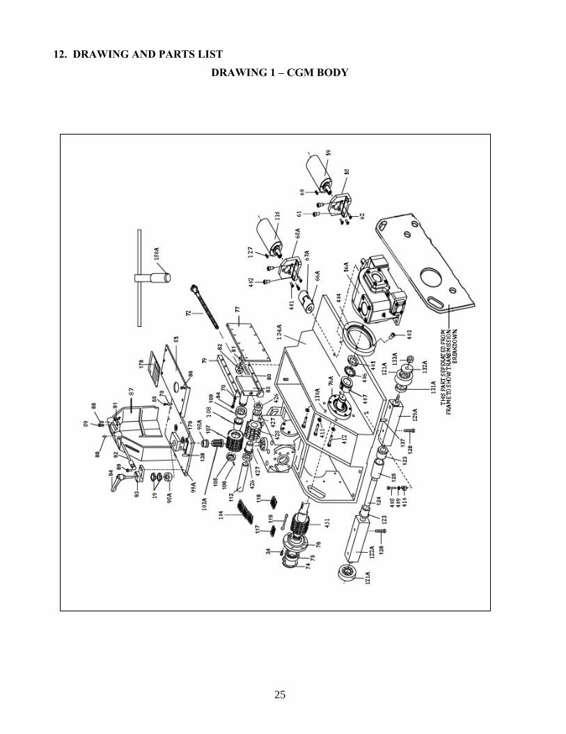
12. DRAWING AND PARTS LIST
DRAWING 1 – CGM BODY
26
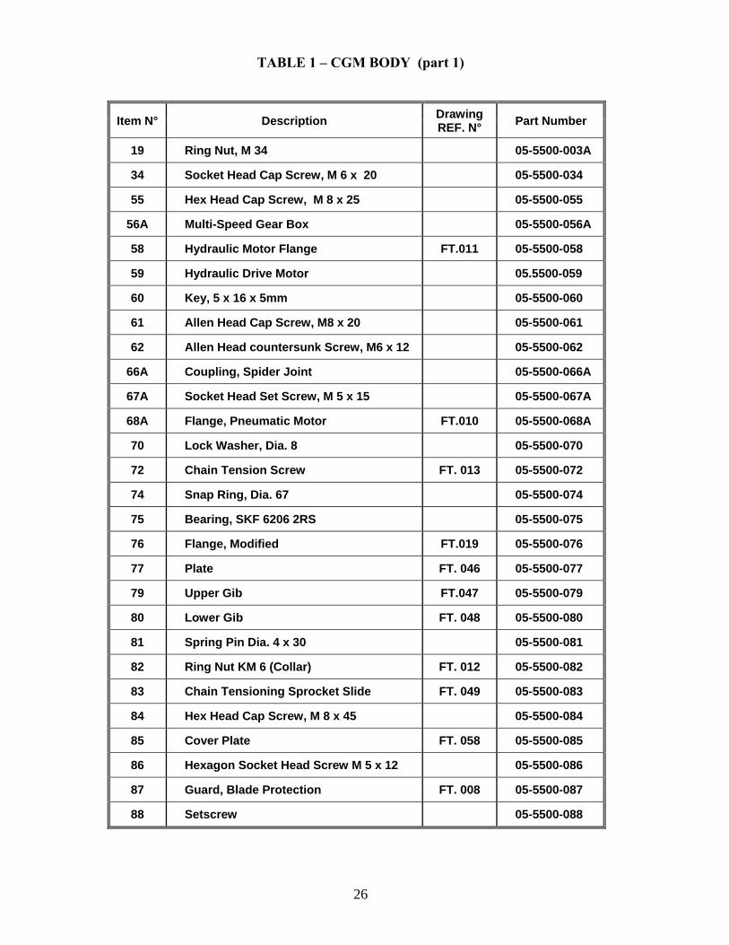
TABLE 1 – CGM BODY (part 1)
Item N° Description Drawing REF. N° Part Number
19 Ring Nut, M 34 05-5500-003A
34 Socket Head Cap Screw, M 6 x 20 05-5500-034
55 Hex Head Cap Screw, M 8 x 25 05-5500-055
56A Multi-Speed Gear Box 05-5500-056A
58 Hydraulic Motor Flange FT.011 05-5500-058
59 Hydraulic Drive Motor 05.5500-059
60 Key, 5 x 16 x 5mm 05-5500-060
61 Allen Head Cap Screw, M8 x 20 05-5500-061
62 Allen Head countersunk Screw, M6 x 12 05-5500-062
66A Coupling, Spider Joint 05-5500-066A
67A Socket Head Set Screw, M 5 x 15 05-5500-067A
68A Flange, Pneumatic Motor FT.010 05-5500-068A
70 Lock Washer, Dia. 8 05-5500-070
72 Chain Tension Screw FT. 013 05-5500-072
74 Snap Ring, Dia. 67 05-5500-074
75 Bearing, SKF 6206 2RS 05-5500-075
76 Flange, Modified FT.019 05-5500-076
77 Plate FT. 046 05-5500-077
79 Upper Gib FT.047 05-5500-079
80 Lower Gib FT. 048 05-5500-080
81 Spring Pin Dia. 4 x 30 05-5500-081
82 Ring Nut KM 6 (Collar) FT. 012 05-5500-082
83 Chain Tensioning Sprocket Slide FT. 049 05-5500-083
84 Hex Head Cap Screw, M 8 x 45 05-5500-084
85 Cover Plate FT. 058 05-5500-085
86 Hexagon Socket Head Screw M 5 x 12 05-5500-086
87 Guard, Blade Protection FT. 008 05-5500-087
88 Setscrew 05-5500-088
27
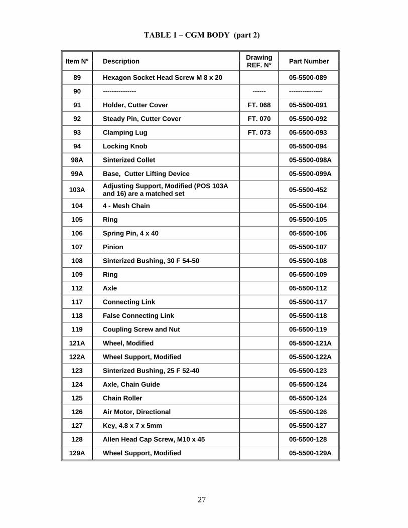
TABLE 1 – CGM BODY (part 2)
Item N° Description Drawing
REF. N° Part Number
89 Hexagon Socket Head Screw M 8 x 20 05-5500-089
90 --------------- ------ ---------------
91 Holder, Cutter Cover FT. 068 05-5500-091
92 Steady Pin, Cutter Cover FT. 070 05-5500-092
93 Clamping Lug FT. 073 05-5500-093
94 Locking Knob 05-5500-094
98A Sinterized Collet 05-5500-098A
99A Base, Cutter Lifting Device 05-5500-099A
103A Adjusting Support, Modified (POS 103A and 16) are a matched set 05-5500-452
104 4 - Mesh Chain 05-5500-104
105 Ring 05-5500-105
106 Spring Pin, 4 x 40 05-5500-106
107 Pinion 05-5500-107
108 Sinterized Bushing, 30 F 54-50 05-5500-108
109 Ring 05-5500-109
112 Axle 05-5500-112
117 Connecting Link 05-5500-117
118 False Connecting Link 05-5500-118
119 Coupling Screw and Nut 05-5500-119
121A Wheel, Modified 05-5500-121A
122A Wheel Support, Modified 05-5500-122A
123 Sinterized Bushing, 25 F 52-40 05-5500-123
124 Axle, Chain Guide 05-5500-124
125 Chain Roller 05-5500-124
126 Air Motor, Directional 05-5500-126
127 Key, 4.8 x 7 x 5mm 05-5500-127
128 Allen Head Cap Screw, M10 x 45 05-5500-128
129A Wheel Support, Modified 05-5500-129A
28
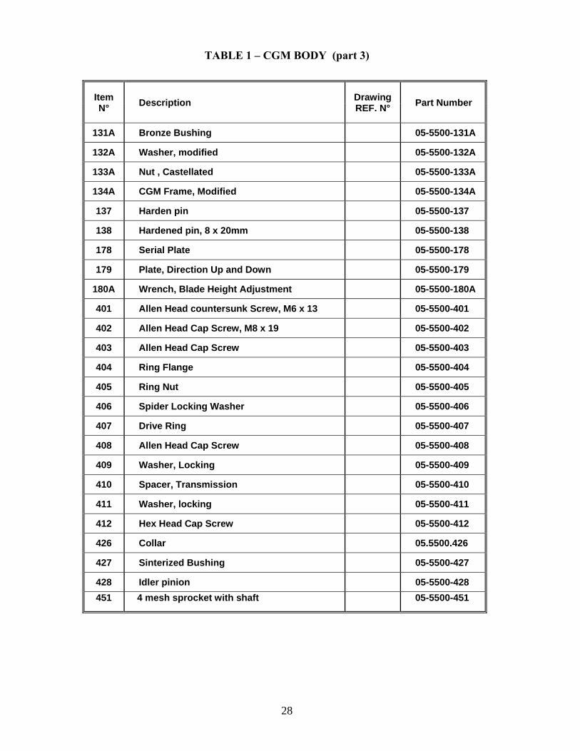
TABLE 1 – CGM BODY (part 3)
Item N° Description Drawing
REF. N° Part Number
131A Bronze Bushing 05-5500-131A
132A Washer, modified 05-5500-132A
133A Nut , Castellated 05-5500-133A
134A CGM Frame, Modified 05-5500-134A
137 Harden pin 05-5500-137
138 Hardened pin, 8 x 20mm 05-5500-138
178 Serial Plate 05-5500-178
179 Plate, Direction Up and Down 05-5500-179
180A Wrench, Blade Height Adjustment 05-5500-180A
401 Allen Head countersunk Screw, M6 x 13 05-5500-401
402 Allen Head Cap Screw, M8 x 19 05-5500-402
403 Allen Head Cap Screw 05-5500-403
404 Ring Flange 05-5500-404
405 Ring Nut 05-5500-405
406 Spider Locking Washer 05-5500-406
407 Drive Ring 05-5500-407
408 Allen Head Cap Screw 05-5500-408
409 Washer, Locking 05-5500-409
410 Spacer, Transmission 05-5500-410
411 Washer, locking 05-5500-411
412 Hex Head Cap Screw 05-5500-412
426 Collar 05.5500.426
427 Sinterized Bushing 05-5500-427
428 Idler pinion 05-5500-428 451 4 mesh sprocket with shaft
05-5500-451
29
DRAWING 2 – CGM TRANSMISSION
30
TABLE 2 – CGM TRANSMISSION (part 1)
Item N° Description Drawing REF. N° Part Number
1 Socket Head Cap Screw, M 6 x 30 05-5500-001
2 Flange FT. 036 05-5500-002
3 Ring Nut KM 6 05-5500-003
4 Iron Washer MB 6 05-5500-004
5 Spacer FT. 037 05-5500-005
6 Bearing SKF, 30206 52 05-5500-006
7 Spacer FT. 031 05-5500-007
8 Flange FT. 035 05-5500-008
9 Spacer FT. 032 05-5500-009
10 Bronze Worm Gear FT. 034 05-5500-010
11 Socket Head Cap Screw, M 6 x 15 05-5500-011
12 Flange FT. 039 05-5500-012
13 Spacer FT. 038 05-5500-013
14 Steel Worm Gear Shaft FT. 052 05-5500-014
15 Socket Head Cap Screw, M 8 x 6 05-5500-015
16 Feed Screw Assembly (16 & 103A sold as matched set) FT. 025 05-5500-452
17 Socket Head Cap Screw, M 6 x 12 05-5500-017
18 Cutter Spindle Gear Housing FT. 060 05-5500-018
19 -------------- -------- ------
20 -------------- -------- ------
21 Guide Rod FT. 029 05-5500-021
22 Washer FT. 028 05-5500-022
23 -------------- -------- ------
24 Sinterized Bushing, 20C 479-30 05-5500-024
25 Flange, Hydraulic Motor FT. 055 05-5500-025
26 Socket Head Cap Screw, M 12 x 30 05-5500-026
27 Lock Washer, Diameter 12mm 05-5500-027
28 Socket Head Cap Screw, M 8 x 30 05-5500-028
29 Pneumatic Motor, Ingersol-Rand 4800M 05-5500-029
31
TABLE 2 – CGM TRANSMISSION (part 2)
Item N° Description Drawing REF. N° Part Number
30 Socket Head Cap Screw, M 8 x 25 05-5500-030
31 Pneumatic Motor Flange FT.054 05-5500-031
32 Socket Head Cap Screw, 5/16 x 20 05-5500-032
33 Flange FT.053 05-5500-033
34 Socket Head Cap Screw, M 6 x 20 05-5500-034
35 Packing Ring,, DH 37 x 47 x 4 05-5500-035
36 Roller Bearing, NK 37/20 A 05-5500-036
37 Snap Ring, Diameter 47mm 05-5500-037
38 Bearing, SKF 6007 05-5500-038
39 Spacer FT.005 05-5500-039
40 Cutter Spindle FT.051 05-5500-040
41 Packing Ring, Nilos 3200Av 05-5500-041
42 Key, B 10 x 8 x 45 05-5500-042
43 Key, B 10 x 8 x 25 05-5500-042
44 Flange FT.030 05-5500-044
45 Metal Packing, OR 3193 05-5500-045
46 Packing , BAU 4 05-5500-046
47 Flange FT.071 05-5500-047
48 Cutter Drive Collar, Male FT.042 05-5500-048
49 Cutter Drive Collar, Female FT.043 05-5500-049
50 Hardened Pin, 10 x 60 (used in item 48) 05-5500-050
51 Cutter Lock Nut FT.062 05-5500-051
52 Cutter Drive Collar, Female FT.044 05-5500-052
53 Hydraulic Motor, OMP 80 DNFS 05-5500-053
89 Socket Head Cap M 8 x 20 05-5500-089
139 Grease Zerk, 1/4" 05-5500-139
445 Column Tensioning Block 05-5500-445
446 Screw, Column Tensioning M6 X 50 05-5500-446
447 Screw, Mounting M6 X 20 05-5500-447
32
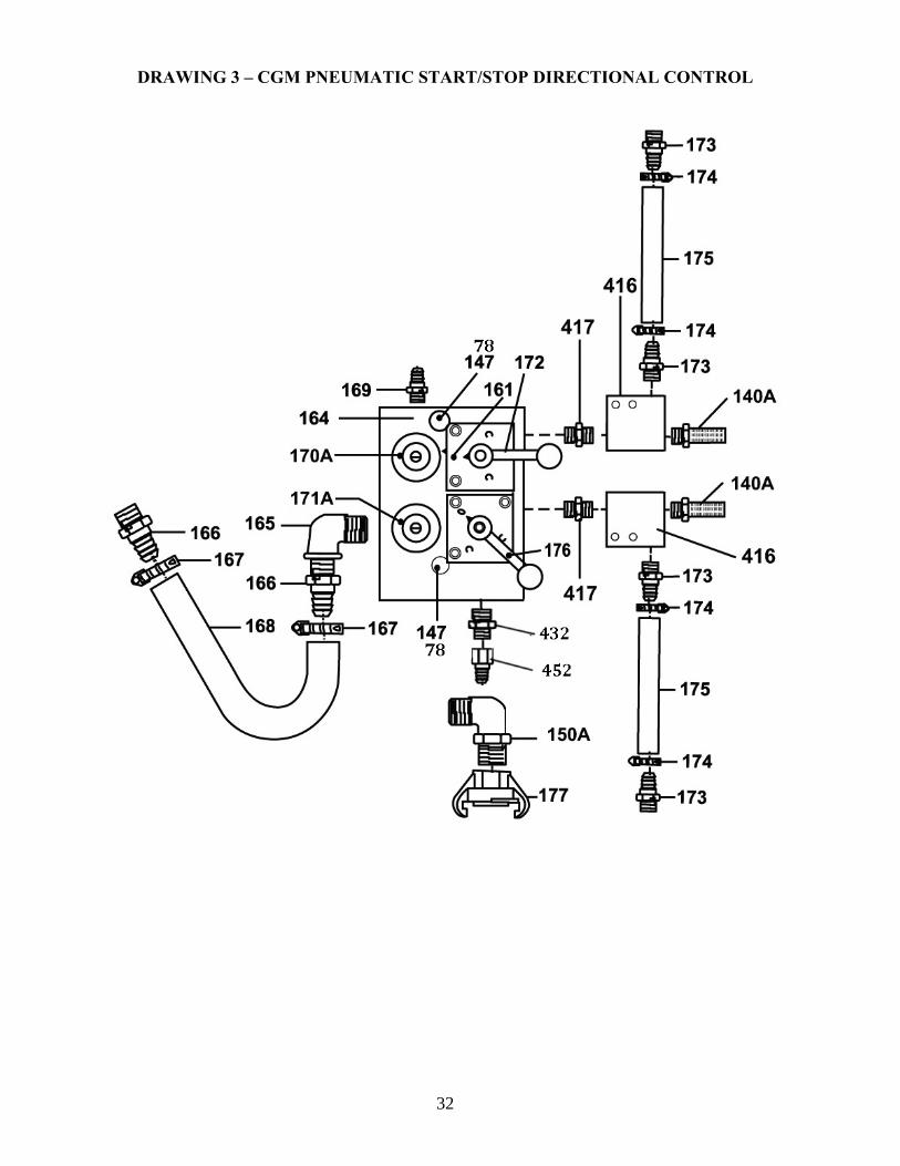
DRAWING 3 – CGM PNEUMATIC START/STOP DIRECTIONAL CONTROL
33
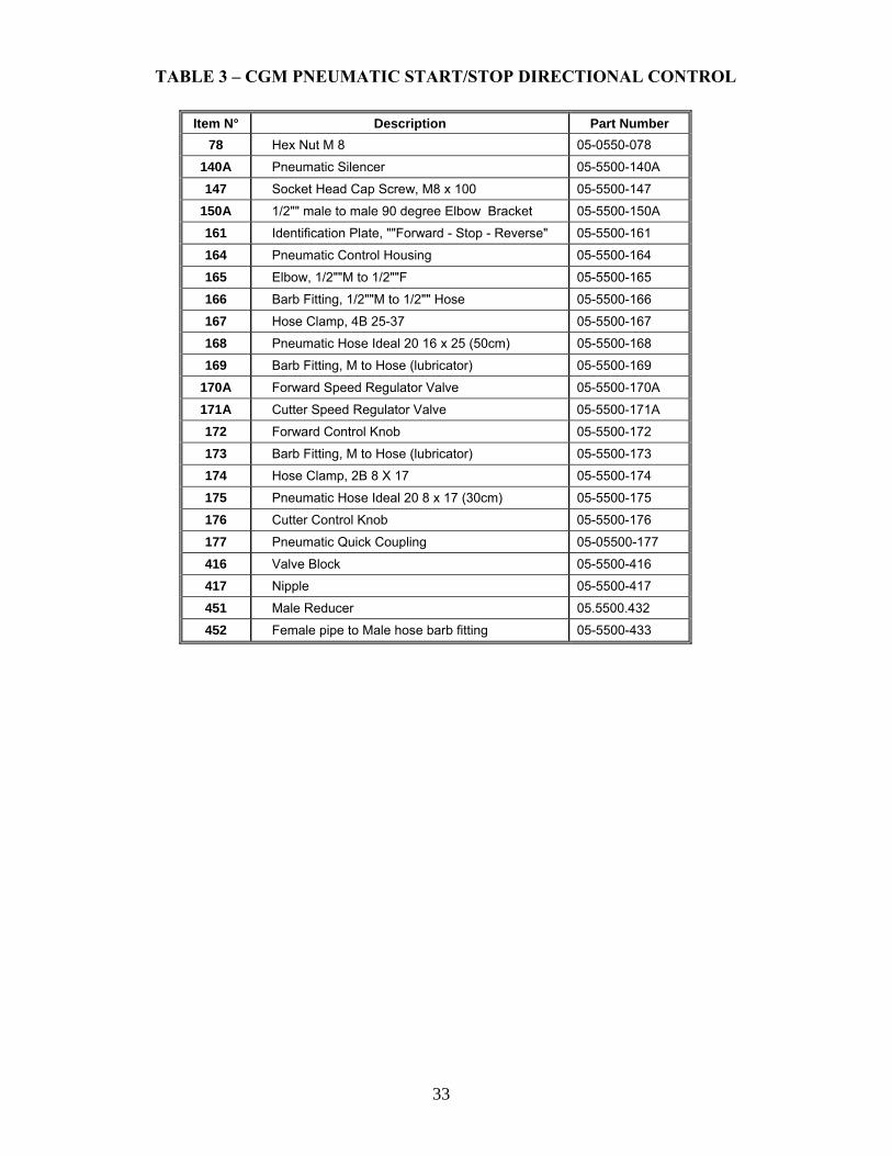
TABLE 3 – CGM PNEUMATIC START/STOP DIRECTIONAL CONTROL Item N° Description Part Number
78 Hex Nut M 8 05-0550-078
140A Pneumatic Silencer 05-5500-140A
147 Socket Head Cap Screw, M8 x 100 05-5500-147
150A 1/2"" male to male 90 degree Elbow Bracket 05-5500-150A
161 Identification Plate, ""Forward - Stop - Reverse" 05-5500-161
164 Pneumatic Control Housing 05-5500-164
165 Elbow, 1/2""M to 1/2""F 05-5500-165
166 Barb Fitting, 1/2""M to 1/2"" Hose 05-5500-166
167 Hose Clamp, 4B 25-37 05-5500-167
168 Pneumatic Hose Ideal 20 16 x 25 (50cm) 05-5500-168
169 Barb Fitting, M to Hose (lubricator) 05-5500-169
170A Forward Speed Regulator Valve 05-5500-170A
171A Cutter Speed Regulator Valve 05-5500-171A
172 Forward Control Knob 05-5500-172
173 Barb Fitting, M to Hose (lubricator) 05-5500-173
174 Hose Clamp, 2B 8 X 17 05-5500-174
175 Pneumatic Hose Ideal 20 8 x 17 (30cm) 05-5500-175
176 Cutter Control Knob 05-5500-176
177 Pneumatic Quick Coupling 05-05500-177
416 Valve Block 05-5500-416
417 Nipple 05-5500-417
451 Male Reducer 05.5500.432
452 Female pipe to Male hose barb fitting 05-5500-433
34
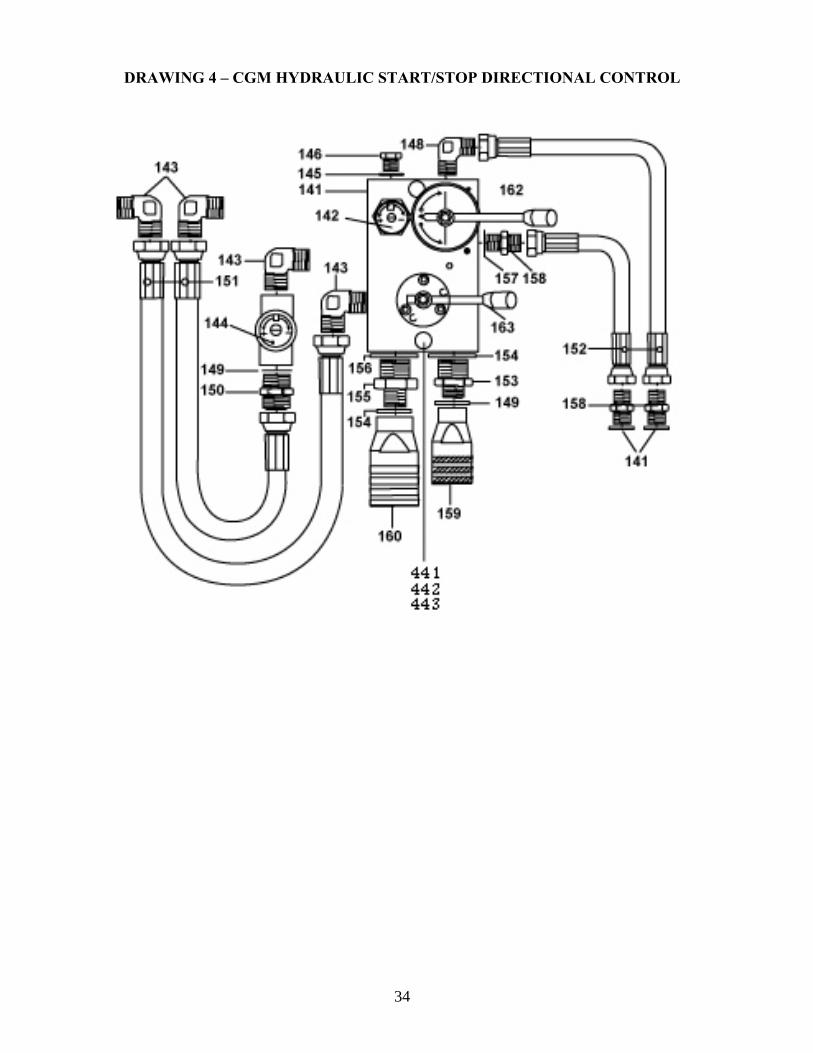
DRAWING 4 – CGM HYDRAULIC START/STOP DIRECTIONAL CONTROL
35
Item N° Description Part Number 78 Hex Nut, M 8 (Not Shown) 05-5500-078
141 Hydraulic Control Housing 05-5500-141 142 Forward Speed Regulator Valve 05-5500-142 143 Elbow, 1/2" 05-5500-143 144 Cutter Speed Regulator 05-5500-144 145 Copper Washer, 1/4" 05-5500-145 146 Plug, 1/4" 05-5500-146 147 Socket Head Cap Screw, M 8 x 100 05-5500-147 148 Elbow, 3/8" 05-5500-148 149 Copper Washer, 1/2" 05-5500-149 150 Nipple, 1/2" 05-5500-150 151 1/2"F to 1/2" F x 20" Long High pressure hose 05-5500-151 152 3/8"F to 1/2"M x 16" Long High pressure hose 05-5500-152 153 3/4" - 1/2" Reducing Nipple 05-5500-153 154 Copper Washer, 3/4" 05-5500-154 155 3/4" - 1" Reducing Nipple 05-5500-155 156 Copper Washer, 1" 05-5500-156 157 Copper Washer, 3/8" 05-5500-154 158 Nipple, 3/8" 05-5500-158 159 1" Female Fast Coupling (Return) 05-5500-160 160 3/4" Female Fast Coupling (Pressure) 05-5500-159
161A Identification Plate "Forward - Stop - Backward" 05-5500-161A 162 Forward Control Knob 05-5500-162 163 Cutter Control Knob 05-5500-163 441 Lock Washer, 8mm 05-5500-441 442 Nut, 8M 05-5500-442 443 Socket heat Cap Screw, 8M x 80mm 05-5500-443
TABLE 4 – CGM HYDRAULIC START/STOP DIRECTIONAL CONTROL
36
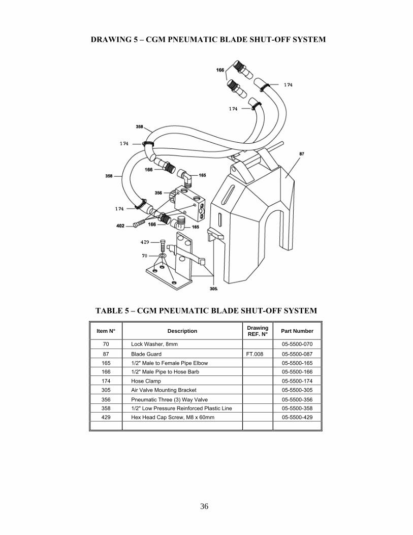
DRAWING 5 – CGM PNEUMATIC BLADE SHUT-OFF SYSTEM
TABLE 5 – CGM PNEUMATIC BLADE SHUT-OFF SYSTEM
Item N° Description Drawing REF. N° Part Number
70 Lock Washer, 8mm 05-5500-070
87 Blade Guard FT.008 05-5500-087
165 1/2" Male to Female Pipe Elbow 05-5500-165 166 1/2" Male Pipe to Hose Barb 05-5500-166
174 Hose Clamp 05-5500-174
305 Air Valve Mounting Bracket 05-5500-305
356 Pneumatic Three (3) Way Valve 05-5500-356 358 1/2" Low Pressure Reinforced Plastic Line 05-5500-358 429 Hex Head Cap Screw, M8 x 60mm 05-5500-429
37
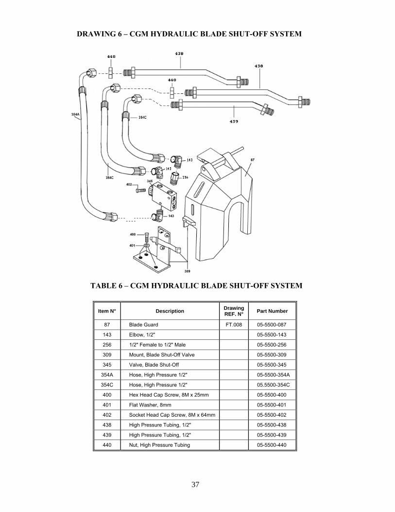
DRAWING 6 – CGM HYDRAULIC BLADE SHUT-OFF SYSTEM
TABLE 6 – CGM HYDRAULIC BLADE SHUT-OFF SYSTEM
Item N° Description Drawing REF. N° Part Number
87 Blade Guard FT.008 05-5500-087
143 Elbow, 1/2" 05-5500-143
256 1/2" Female to 1/2" Male 05-5500-256
309 Mount, Blade Shut-Off Valve 05-5500-309
345 Valve, Blade Shut-Off 05-5500-345
354A Hose, High Pressure 1/2" 05-5500-354A
354C Hose, High Pressure 1/2" 05.5500-354C
400 Hex Head Cap Screw, 8M x 25mm 05-5500-400
401 Flat Washer, 8mm 05-5500-401
402 Socket Head Cap Screw, 8M x 64mm 05-5500-402
438 High Pressure Tubing, 1/2" 05-5500-438
439 High Pressure Tubing, 1/2" 05-5500-439
440 Nut, High Pressure Tubing 05-5500-440
38
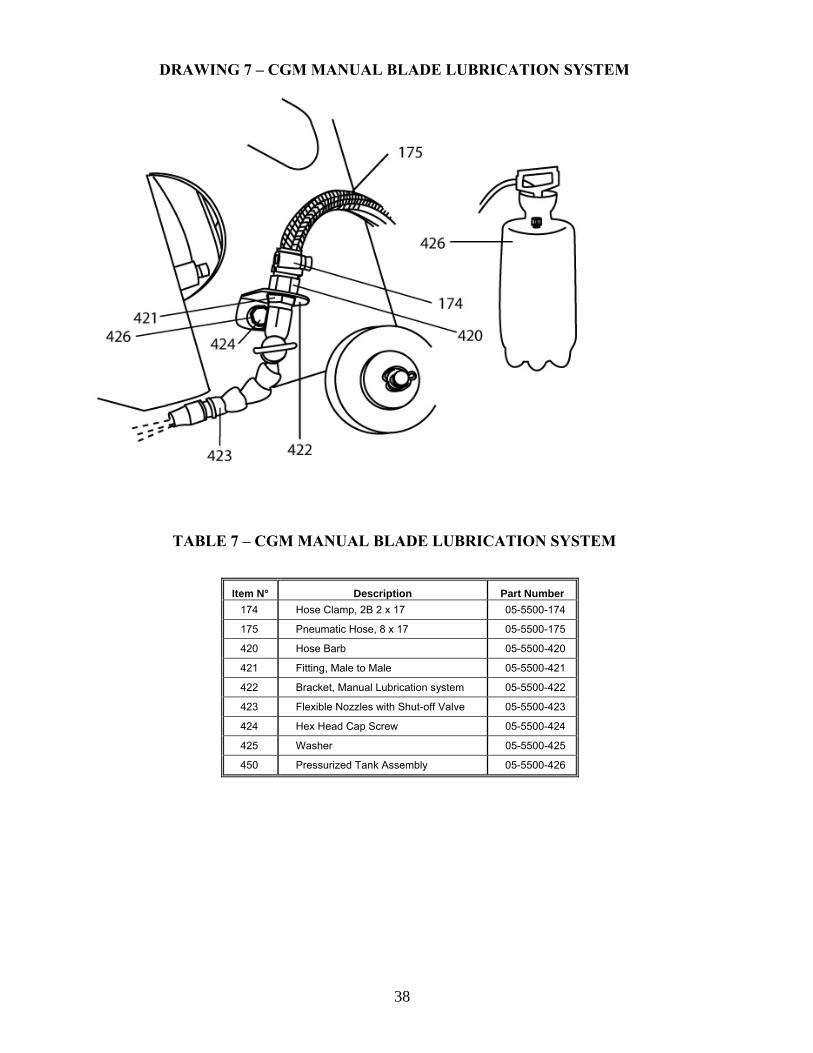
DRAWING 7 – CGM MANUAL BLADE LUBRICATION SYSTEM
TABLE 7 – CGM MANUAL BLADE LUBRICATION SYSTEM Item N° Description Part Number
174 Hose Clamp, 2B 2 x 17 05-5500-174
175 Pneumatic Hose, 8 x 17 05-5500-175
420 Hose Barb 05-5500-420
421 Fitting, Male to Male 05-5500-421
422 Bracket, Manual Lubrication system 05-5500-422
423 Flexible Nozzles with Shut-off Valve 05-5500-423
424 Hex Head Cap Screw 05-5500-424
425 Washer 05-5500-425
450 Pressurized Tank Assembly 05-5500-426
39
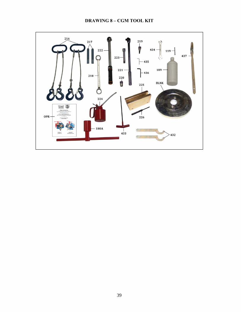
DRAWING 8 – CGM TOOL KIT
40
TABLE 8 – CGM TOOL KIT
Item N° Description Part Number
119 Chain Coupling Screw and Nut 05-5500-119
180A Wrench, Blade Height Adjustment 05.5500.180A
216 Lifting Slings 05-5500-216
217 Wedges 05-5500-217
218 30 - 32 Wrench 05-5500-218
219 8mm Hexagon key Socket 05-5500-219
220 16mm Hexagon drive socket 05-5500-220
221 Elbow Wrench with Bayonet 05-5500-221
222 Torque Wrench 05-5500-222
223 4" Extension 05-5500-223
225 Chain Block, Pin Driver 05-5500-225
226 Pin Driver, 4 Mesh Chain 05-5500-226
432 C Spanner 05-5500-432
433 Long 6mm Socket Hexagon "T" Handle 05-5500-433
434 12 - 13 mm Wrench 05-5500-434
435 Socket, Hexagon 2,5mm 05-5500-435
436 Socket, Hexagon 5mm 05-5500-436
OPR CGM Operating Manual 05-5500-OPR
BLNK Blade Blank 05-5500-BLNK
CGM Storage Box (Not Shown) 05.5500.BOX
No longer furnish with machine / Must be purchased separately
189 Plastic Bottle, Synthetic Coolant 05-5500-189
224 Oiler 05-5500-224
437 Chip Brush 05-5500-437
41
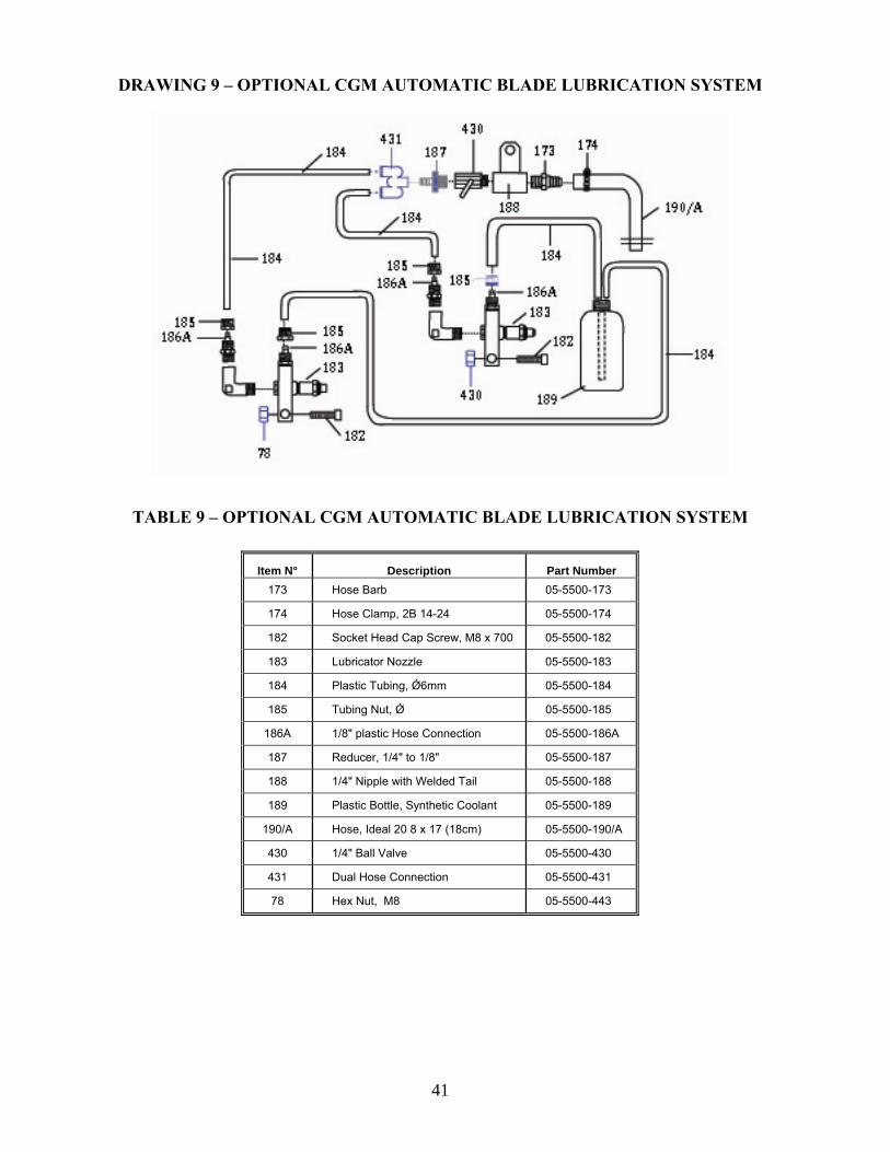
DRAWING 9 – OPTIONAL CGM AUTOMATIC BLADE LUBRICATION SYSTEM
TABLE 9 – OPTIONAL CGM AUTOMATIC BLADE LUBRICATION SYSTEM Item N° Description Part Number
173 Hose Barb 05-5500-173
174 Hose Clamp, 2B 14-24 05-5500-174
182 Socket Head Cap Screw, M8 x 700 05-5500-182
183 Lubricator Nozzle 05-5500-183
184 Plastic Tubing, Ǿ6mm 05-5500-184
185 Tubing Nut, Ǿ 05-5500-185
186A 1/8" plastic Hose Connection 05-5500-186A
187 Reducer, 1/4" to 1/8" 05-5500-187
188 1/4" Nipple with Welded Tail 05-5500-188
189 Plastic Bottle, Synthetic Coolant 05-5500-189
190/A Hose, Ideal 20 8 x 17 (18cm) 05-5500-190/A
430 1/4" Ball Valve 05-5500-430
431 Dual Hose Connection 05-5500-431
78 Hex Nut, M8 05-5500-443
42
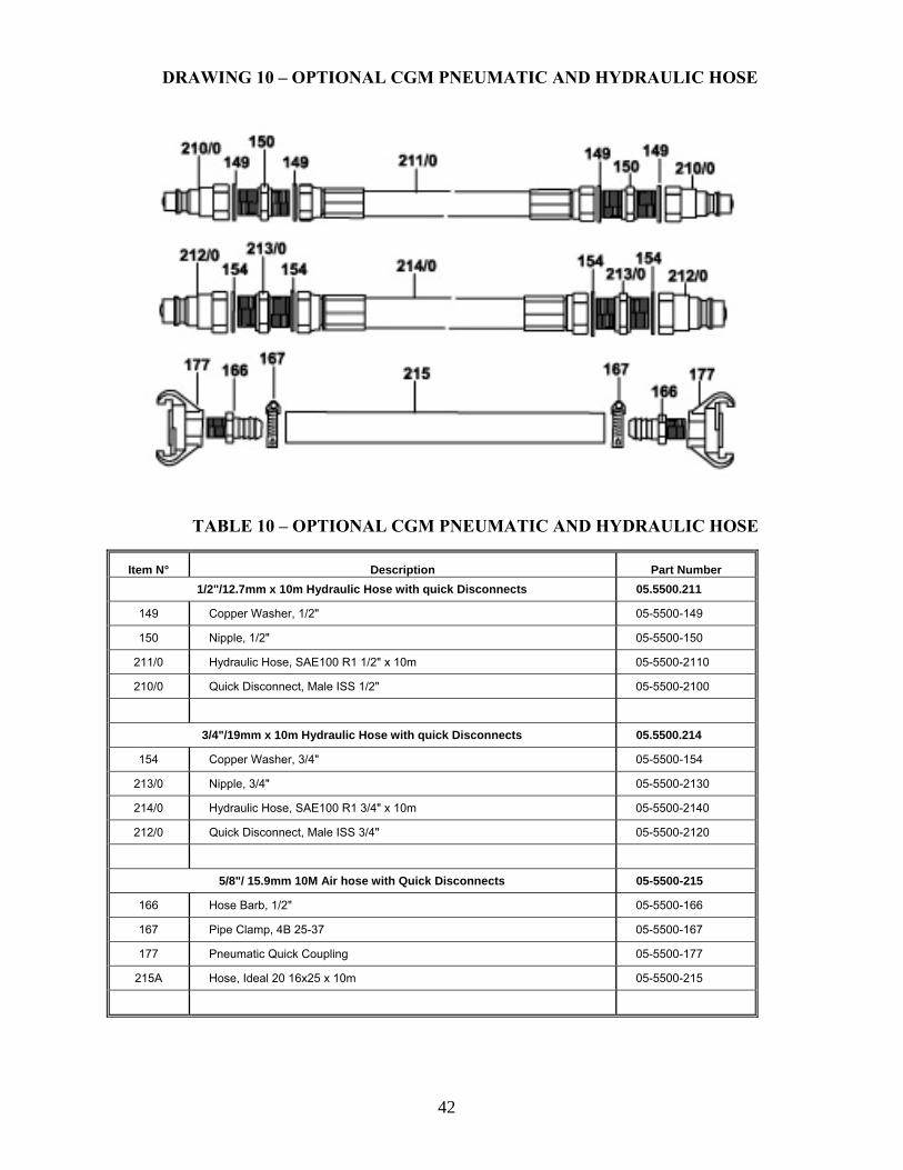
DRAWING 10 – OPTIONAL CGM PNEUMATIC AND HYDRAULIC HOSE
TABLE 10 – OPTIONAL CGM PNEUMATIC AND HYDRAULIC HOSE
Item N° Description Part Number 1/2"/12.7mm x 10m Hydraulic Hose with quick Disconnects 05.5500.211
149 Copper Washer, 1/2" 05-5500-149
150 Nipple, 1/2" 05-5500-150
211/0 Hydraulic Hose, SAE100 R1 1/2" x 10m 05-5500-2110
210/0 Quick Disconnect, Male ISS 1/2" 05-5500-2100
3/4"/19mm x 10m Hydraulic Hose with quick Disconnects 05.5500.214
154 Copper Washer, 3/4" 05-5500-154
213/0 Nipple, 3/4" 05-5500-2130
214/0 Hydraulic Hose, SAE100 R1 3/4" x 10m 05-5500-2140
212/0 Quick Disconnect, Male ISS 3/4" 05-5500-2120
5/8"/ 15.9mm 10M Air hose with Quick Disconnects 05-5500-215
166 Hose Barb, 1/2" 05-5500-166
167 Pipe Clamp, 4B 25-37 05-5500-167
177 Pneumatic Quick Coupling 05-5500-177
215A Hose, Ideal 20 16x25 x 10m 05-5500-215
43
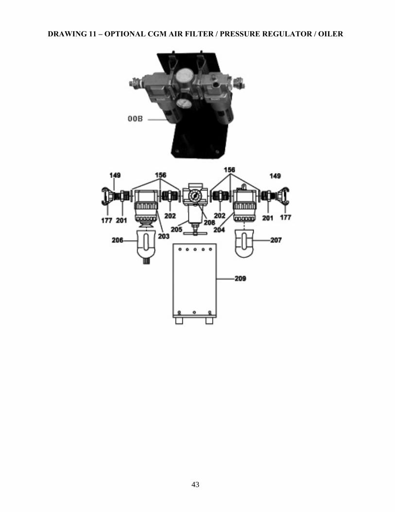
DRAWING 11 – OPTIONAL CGM AIR FILTER / PRESSURE REGULATOR / OILER
44
TABLE 11 – OPTIONAL CGM AIR FILTER / PRESSURE REGULATOR / OILER
13. Warranty If any merchandise sold hereunder (except merchandise manufactured by other persons or firms) by Mathey Dearman, Inc. (the “Company”) is not in accordance with specifications shown on the order within customarily accepted tolerances, or is defective on account of workmanship or material, and if such merchandise is returned at the customer’s expense and rise, to the Company’s manufacturing facility (or at the Company’s option, is returned to a repair facility authorized by the Company), within ninety (90) days after the Company’s date of shipment thereof, the Company will, at its option, replace or repair the merchandise. This agreement, however, is upon the conditions: (A) that the customer promptly notifies the Company in writing of any claim under this agreement, setting forth in detail any such claimed defect. (B) That the Company be afforded a reasonable opportunity to examine the merchandise and to investigate the claimed defect at the Company’s manufacturing facility or at an authorized repair facility, the Company shall not be, in any event, liable for damages beyond the price paid by the customer for such defective merchandise; specifically but without limitation, the Company may fulfill its obligations under this Agreement by tendering such purchase price at any time. THE COMPANY SHALL NOT BE LIABLE FOR CONSEQUENTIAL, INCIDENTAL, PUNITITVE, OR EXEMPLARY DAMAGES. This agreement does not obligate the Company to bear any transportation charges in connection with the replacement or the repair of defective merchandise. As to any item manufactured by other persons or firms, the Company agrees to present a request for adjustment for repair to such manufacturer, and the customer agrees that the liability of the Company shall not exceed any adjustment with respect to which such manufacturer accepts responsibility. THE ABOVE AGREEMENT IS IN LIEU OF ALL WARRANTIES, EXPRESSED OR IMPLIED AND IT IS AGREED THAT THERE IS NO EXPRESSED OR IMPLIED WARRANTY BY THE COMPANY AS TO THE FITNESS, MERCHANTABILITY CAPACITY, OR EFFICIENCY OF ANY MERCHANDISE SOLD, AND THAT THERE ARE NO ORAL OR WRITTEN EXPRESSED OR IMPLIED WARRANTIES MADE IN CONNECTION WITH ANY SALE BY THE COMPANY. No modification or addition to this agreement, either before or after the contract of sale, shall be made except on written authority of the President or Vice President of the Company.
C.I.A. Mathey Italiana S.r.l. Via Isonzo, 26 - 20050 S. Damiano di Brugherio (MI)
Phone: +39 039 831019/2020021 • Fax: +39 039 2020079 [email protected] • www.ciamathey.com
Item N° Description Part Number Air Filter/ Regulator / Oiler (Complete) 05-5500-00B
149 Copper Washer, 1/2" 05-5500-149 156 Copper Washer, 1" 05-5500-156 177 Pneumatic Quick Coupling 05-5500-177 201 Reducing Nipple, 1" - 1/2" 05-5500-201 202 Nipple, 1" 05-5500-202 203 Air Filter Assembly 05-5500-203 204 Lubricator Assembly 05-5500-204 205 Pressure Regulator Valve 05-5500-205 206 Vapor Condensation Reservoir 05-5500-206 207 Oil Reservoir 05-5500-207 208 Pneumatic Pressure Gauge 05-5500-208
209 Filter Assembly Base 05-5500-20