cfd modelling of mass transfer with and without chemical ... · pdf fileuniversity of dortmund...
TRANSCRIPT

University of Dortmund
CFD modelling of mass transfer with and without chemical reaction
in liquid-liquid slug flow capillary microreactors
M. N. Kashid1,2, D. W. Agar1 and S. Turek2
1Institute of Reaction Engineering (TCB)&
2Institute for Applied Mathematics (LSIII)University of Dortmund
Germany

ISCRE Presentation – 6th September, 2006 Institute of Reaction Engineering&
Institute for Applied Mathematics
University of Dortmund
Outline
Introduction
Motivation & objectives
CFD model
Model validation
Closing remarks

ISCRE Presentation – 6th September, 2006 Institute of Reaction Engineering&
Institute for Applied Mathematics
University of Dortmund
Introduction - Micoreactor technology
Appeal of small scales to chemical engineers:
Important technique for process intensification
Improved performance due to high specific surface areas enhancing heat and mass transfer
Enhanced mass transfer increases reaction rates & reduces process volumes
Precise control of highly exothermic and hazardous reactions
Numbering-up instead of scale-up

ISCRE Presentation – 6th September, 2006 Institute of Reaction Engineering&
Institute for Applied Mathematics
University of Dortmund
Introduction - slug flow reactor
An alternative to suspended drop or film contactor ?
Uniform, well-defined slug size
High specific interfacial area
Enhanced mass transferRecirculationRecirculation Diffusion
DiffusionSlug Flow
Stratified Flow
PIV Measurement
Velocity vectors
CFD simulations
CFD particle tracingTaylor-like vortices - Internal circulations

ISCRE Presentation – 6th September, 2006 Institute of Reaction Engineering&
Institute for Applied Mathematics
University of Dortmund
Introduction- slug flow reactor (..continued)
Facile temperature profiling along the reactor Straightforward downstream phase separation
Outlet 2 – Teflon
Outlet 1 – steel
InletAqueous phase
Organic phase

ISCRE Presentation – 6th September, 2006 Institute of Reaction Engineering&
Institute for Applied Mathematics
University of Dortmund
Motivation & ObjectivesSlug flow concept & mass transfer performance (Burns and Ramshaw, 2001; Harries et al., 2003)
Elucidation & optimisation of nitration reactions(Dummann et al. 2003; Loebbecke et al, 2003)
Fundamental hydrodynamic modelling (Kashid et. al. 2005; Kashid et. al. 2006; Kashid and Agar, 2006)
Prediction of mass transfer rates and reaction(ISCRE 2006)
Powerful experimental tool for analysing biphasic reactions
Identification of asymptotic limits for technical processes

ISCRE Presentation – 6th September, 2006 Institute of Reaction Engineering&
Institute for Applied Mathematics
University of Dortmund
CFD Modelling - Volume of Fluid (VOF)
Incompressible Navier-Stokes equation
The indicator function
Surface tension + wall adhesion
Assumption: No mass transfer between phasesIsothermal conditions
Commercial CFD software package, Fluent 6.2
. 0α α∂+ ∇ =
∂k
k kut
( ) [ ]( )[ ]
∑∑∑ ==
=∇
+∇+∇⋅∇−∇−=⋅∇+∂∂
kk
kkkkk
SFT
u
Fuupuutu
ραμρα
μραρ
ρμ
ρ
and,where
0
11
Experimental: (ID = 1 mm, Velocity = 20 mm/s)
CFD: (ID = 1 mm, Velocity = 20 mm/s)
ISCRE Presentation – 6th September, 2006 Institute of Reaction Engineering&
Institute for Applied Mathematics
University of Dortmund
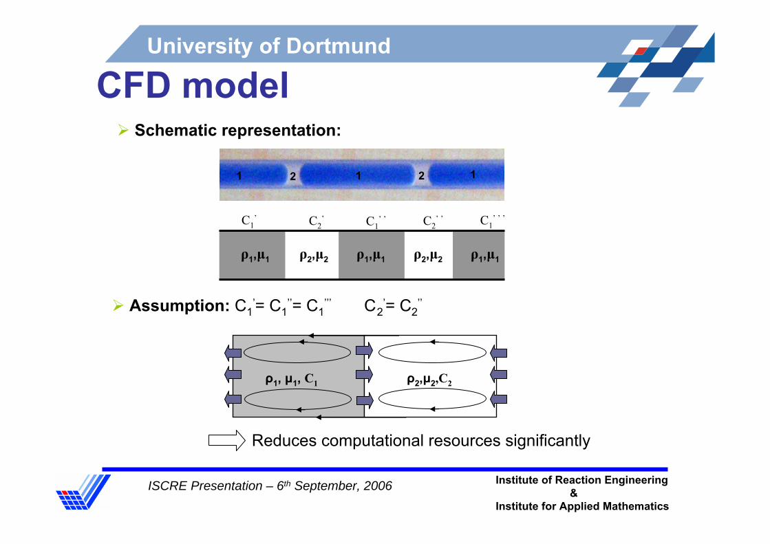
CFD model
ρ1, μ1, C1 ρ2,μ2,C2
Assumption: C1’= C1
’’= C1’’’ C2
’= C2’’
Schematic representation:
Reduces computational resources significantly
C1’ C2
’ C1’ ’ C1
’ ’ ’C2’ ’
ρ1,μ1 ρ2,μ2 ρ1,μ1 ρ2,μ2 ρ1,μ1
1 21 2 1

ISCRE Presentation – 6th September, 2006 Institute of Reaction Engineering&
Institute for Applied Mathematics
University of Dortmund
Governing Equations – fluid flow
( ) ( )[ ]0u
T][0,x Ωuuu 2
=∇
ℜ∈∇−∇+∇⋅∇=∇⋅+∂
∂ puut
Tμρρ
Assumptions
Slugs are Newtonian, viscous and imcompressibleShape of the slug and volume invariant Flow is laminar and mass diffusivity constantMass transfer and reaction does not affect the flow patterns within the slugs
Density and viscosity ( ))X(
X
0
0
ff
μμρρ
==
Interface condition 2
22
1
11 n n
uu∂∂
=∂∂ μμ
Flow field
ISCRE Presentation – 6th September, 2006 Institute of Reaction Engineering&
Institute for Applied Mathematics
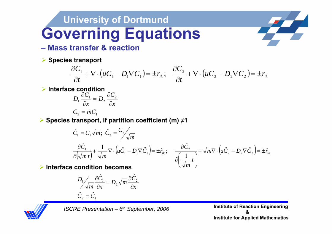
University of DortmundGoverning Equations– Mass transfer & reaction
12
22
11
mCCx
CDxCD
=∂
∂=
∂∂
12
22
11
ˆˆ
ˆˆ
CCx
CmDx
Cm
D
=∂
∂=
∂∂
Species transport
( ) ( ) ikik rCDuCt
CrCDuC
tC
±=∇−⋅∇+∂
∂±=∇−⋅∇+
∂∂
2222
1111 ;
Species transport, if partition coefficient (m) ≠1
Interface condition
Interface condition becomes
( ) ( ) ( ) ikik rCDCumt
m
CrCDCumtm
Cm
CCmCC
ˆˆˆ1
ˆ;ˆˆˆ1ˆ
ˆ;ˆ
2222
1111
2211
±=∇−⋅∇+
⎟⎟⎠
⎞⎜⎜⎝
⎛∂
∂±=∇−⋅∇+
∂
∂
==

ISCRE Presentation – 6th September, 2006 Institute of Reaction Engineering&
Institute for Applied Mathematics
University of Dortmund
Boundary conditions
ρ1,μ1,, C1 ρ2,μ2,C2
Moving Wall, Vwall = Vav
Moving Wall, Vwall = Vav
Stationay Interface,
Vint = 0
Stationay Interface,
Vint = 0
Stationay Interface,
Vint = 0
No-slip at the moving walls Zero species flux at the moving wallsPeriodic boundary concept to connect the extremities of domainMoving boundary concept to set velocity of interface Interface and periodically connected interface satisfies:
Fluid flow
Species transport
xu
xu
∂∂
=∂∂ 2
21
1 μμ
12
22
11
ˆˆ
ˆˆ
CCx
CmD
xC
mD
=∂
∂=
∂∂

ISCRE Presentation – 6th September, 2006 Institute of Reaction Engineering&
Institute for Applied Mathematics
University of Dortmund
SolutionPhysical properties defined using Heaviside function
Terms in the Convection-diffusion equations for m ≠ 1
⎩⎨⎧
Χ>Χ≤
=xwhenxwhen
yxH01
),(
( ) ( )
( )
( ) ( ) ( ) ( ) ( )yxHCDmCDm
CDmCD
yxHCumCum
CumCu
yxHt
m
Ctm
C
tm
CtC
,ˆˆˆˆ1ˆˆˆˆ
,ˆˆ1ˆˆ
,1
ˆˆ
1
ˆˆ
221122
221122
212
⎟⎠
⎞⎜⎝
⎛ ∇⋅∇−∇⋅∇+∇⋅∇=∇⋅∇
⎟⎠
⎞⎜⎝
⎛ ∇⋅−∇⋅+∇⋅=∇⋅
⎟⎟⎟⎟⎟
⎠
⎞
⎜⎜⎜⎜⎜
⎝
⎛
⎟⎠
⎞⎜⎝
⎛∂
∂−
∂∂
+⎟⎠
⎞⎜⎝
⎛∂
∂=
∂∂
( ) ),(property,Physical 212 yxHφφφφ −+=

ISCRE Presentation – 6th September, 2006 Institute of Reaction Engineering&
Institute for Applied Mathematics
University of Dortmund
Solution (… continued)Reaction solution, straightforward operator splitting strategy, within each time step, Step 1: Solution of convection-diffusion equations, all in parallel
Step 2: Obtained concentration field used as initial data for reaction ODE
Discretisation: time → implicit BE, space → FEMFlux correction → upwindEquations are implemented in FEATFLOWTransient simulations
nn ttt −=Δ +1
( ) 0. =∇∇−∇+∂
∂ikikik
ik CDCut
C
ikik r
dtdC
±=

ISCRE Presentation – 6th September, 2006 Institute of Reaction Engineering&
Institute for Applied Mathematics
University of Dortmund
Results - fluid flow
Phase 1
x
y
Phase 2
T = 0.012 s
T = 0.036 s
T = 0.06 s
T = 0.084 s
Test simulation
m/s0.3x10υm/s0.3x10υ 32
51
−− ==
Slug flow velocity = 10 m/sSlug diameter = 0.5 mmSlug length = 2 mm

ISCRE Presentation – 6th September, 2006 Institute of Reaction Engineering&
Institute for Applied Mathematics
University of Dortmund
Results – mass transfer
0
0.2
0.4
0.6
0.8
1
0 2 4 6 8 10
Time [s]
k La
[s-1]
Mesh Level 3 - 80 x 16Level 4 - 160 x 32Level 5 - 320 x 64Level 6 - 640 x 128
Level 3
Level 4
Level 5
Level 6
0
0.002
0.004
0.006
0.008
0.01
0 2 4 6 8 10Time [s]
kL [m
/s
Level 3
Level 4
Level 5
Level 6
Fig: Mass transfer coefficients
Water – succinic acid – n-butanol Capillary ID = 0.5 mmInitial conc. in aqueous solution = 10 Kg/m3
Volumetric mass transfer coefficient
( )( )⎥⎦
⎤⎢⎣
⎡
−−
=outsat
insatL CC
CCT
ak,2,2
,2,2ln1

ISCRE Presentation – 6th September, 2006 Institute of Reaction Engineering&
Institute for Applied Mathematics
University of Dortmund
Model Validation - Neutralisation Reaction
Neutralisation reaction (Harries et al. 2003)
Rapid, second order (k= 1.35 x 10¹¹ L mol-1 s-1) → implicit treatment for reaction ODEsReaction medium: aqueous phasePartitioning of Acetic Acid in favour of aqueous phase: 85:1Governing equations – for species transport in water slug
Kerosene + Acetic acid Water + KOH/NaOH(Reaction Zone)
3 3 2CH + → +COOH NaOH CH COONa H O
( )
( )
( )
( ) 2212424242242
2212323232232
2212222222222
2212121212212
.
.
.
.
CkCCDCut
C
CkCCDCut
C
CkCCDCut
C
CkCCDCut
C
=∇∇−∇+∂
∂
=∇∇−∇+∂
∂
−=∇∇−∇+∂
∂
−=∇∇−∇+∂
∂

ISCRE Presentation – 6th September, 2006 Institute of Reaction Engineering&
Institute for Applied Mathematics
University of Dortmund
Reaction Simulations
0
0.05
0.1
0.15
0.2
0.25
0.3
0 0.5 1 1.5 2 2.5 3
Time [s]
C[m
ol/
CH3COOHNaOHCH3COONa
Average concentrations in aqueous phase
0
2
4
6
8
Level 3 Level 4 Level 5 Level 6 Level 7
Level of refinement
Titra
tion
time
1.75 mm/s3.33 mm/s5.5 mm/s
Mesh independent solution
Data used for chemical reaction simulation
Flow ratio (aqueous/organic): 1Slug lengths : 1.5-3.8 mmSlug diameter: 0.38 mmSlug flow velocities: 0.6-16.6 mm/s
Density ratio (kerosene/water): 0.8Viscosity ratio (kerosene/water): 1.82 Initial conc. of CH3COOH in kerosene: 0.5 mol/LInitial conc. of CH3COOH in water: 0 mol/LInitial conc. of NaOH in water: 0.25 mol/LInitial conc. of CH3COONa in water: 0 mol/LPartition coefficient for CH3COOH (m): 85
Smallest cell size: 0.008D mmSmallest time step for u and p: 1 x10⁻⁴ sTime step for mass transfer & reaction: 1x10⁻⁵ s

ISCRE Presentation – 6th September, 2006 Institute of Reaction Engineering&
Institute for Applied Mathematics
University of Dortmund
Results
CH3COOH NaOH CH3COONa
Simulated snapshots for neutralisation reaction (Titration time = 5.24s)
Time
Fig: Velocity vectors

ISCRE Presentation – 6th September, 2006 Institute of Reaction Engineering&
Institute for Applied Mathematics
University of Dortmund
Comparison
0
2
4
6
8
10
0 4 8 12 16 20Flow velocity [mm/s]
Titra
tion
time
Experimental (Harries et al., 2003)Simulation (Harries et. al., 2003)Present work
0
2
4
6
8
10
0 1 2 3 4 5
Slug length [mm]
Titra
tion
time
Experimental (Harries et al., 2003)Simulations (Harries et. al., 2003)Present work
Titration time vs flow velocity Titration time vs slug length
End point of the titration was taken at 95 % base neutralisation
ISCRE Presentation – 6th September, 2006 Institute of Reaction Engineering&
Institute for Applied Mathematics
University of Dortmund
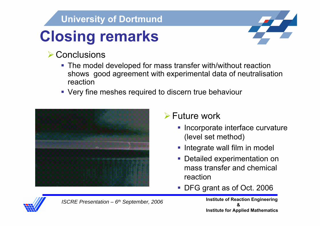
Closing remarksConclusions
The model developed for mass transfer with/without reaction shows good agreement with experimental data of neutralisation reactionVery fine meshes required to discern true behaviour
Future workIncorporate interface curvature (level set method)Integrate wall film in model Detailed experimentation on mass transfer and chemical reaction DFG grant as of Oct. 2006
ISCRE Presentation – 6th September, 2006 Institute of Reaction Engineering&
Institute for Applied Mathematics
University of Dortmund
Thank you for your attention

ISCRE Presentation – 6th September, 2006 Institute of Reaction Engineering&
Institute for Applied Mathematics
University of Dortmund
ReferencesBurns, J. R. and Ramshaw, C., Lab on a Chip, 1,10-15, 2001Harries et al., International Journal of Heat & Mass Transfer, 46, 3313-3322, 2003Dummann et al., Catalysis Today, 79-80, 433-439, 2003Kashid et al., Industrial & Engineering Chemistry Research, 44(14), 5003-5010, 2005 Vandu et al., Chemical Engineering Science, 60(22), 6430-6437, 2005Tamir, A., Impinging Stream Reactors: Fundamentals and Applications, Elsevier: Amsterdam, The Netherlands, 1994Dehkordi Asghar Molaei, Industrial & Engineering Chemistry Research, 40, 681-688, 2001.Berman, Y. and Tamir, A., AIChE Journal, 46 (4), 769, 2000

ISCRE Presentation – 6th September, 2006 Institute of Reaction Engineering&
Institute for Applied Mathematics
University of Dortmund
Slug Flow Generation
Y-Junction FlowExperimental
(Y-junction ID = 1 mm, Capillary ID = 1 mm,Slug Flow Velocity = 20 mm/s)
Y-Junction FlowCFD Simulation (Fluent(R))(Y-junction ID = 1 mm, Capillary ID = 1 mm,Slug Flow Velocity = 2 mm/s )

ISCRE Presentation – 6th September, 2006 Institute of Reaction Engineering&
Institute for Applied Mathematics
University of Dortmund
0
2
4
6
8
10
0 2 4 6 8 10
Time [s]
C [k
g/m3 ]
Conc - Phase 1Conc - Phase 2
Level 3
Level 4
Level 5
Level 6
Level 6
Level 5
Level 4
Level 3
Mesh Level 3 - 80 x 16Level 4 - 160 x 32Level 5 - 320 x 64Level 6 - 640 x 128

ISCRE Presentation – 6th September, 2006 Institute of Reaction Engineering&
Institute for Applied Mathematics
University of Dortmund
Hydrodynamics - Experimentation
P1, P2 - Piston Pumps PT - Pressure TransducerY-jn -Y-junction CM - Capillary MicroreactorL - LightCC - Commercial CameraW - Water CH - Cyclohexane
Operating Conditions:
0-1Pressure Sensor, bar
0.5, 0.75 and 1 Y-junction ID, mm
0.5, 0.75 and 1 Capillary ID, mm
0 – 100 (each phase)Flow rate, ml/hr
Water - CyclohexaneSystem
Experimental Set-up:
P2
P1
Y-jnCM
PTPT
L
CC
CH
W
PT
PT
Slug Flow
Drop Flow
Deformed Interface Flow
Water (+ Brilliant Blue)
Cyclohexane
0
40
80
120
160
0 40 80 120 160
Inlet flow velocity of cyclohexane [mm/s]
Inle
t flo
w v
eloc
ity o
f wat
er [m
m/s
]
Slug flow
Drop Flow
Deformed Interface Flow
ID = 0.5 mm ID = 0.75mm ID = 1 mm
Flow Regime:

ISCRE Presentation – 6th September, 2006 Institute of Reaction Engineering&
Institute for Applied Mathematics
University of Dortmund
Slug Size
b) Unequal inlet flow rates(Water Flow Rate = 10 ml/hr, Y-junction ID = 0.5 mm,
Capillary ID = 0.5 mm)
0
0.5
1
1.5
2
2.5
0 20 40 60 80
Slug Flow Velocity [mm/s]
Slu
g V
olum
e [ μ
l]
ID = 1 mmID = 0.75 mmID = 0.5 mm
0
0.5
1
1.5
2
2.5
3
4 8 12 16 20 24Slug Flow Velocity [mm/s]
Slu
g V
olum
e [ μ
l]
WaterCyclohexane
a) Equal inlet flow rates(Y-junction ID = 0.5 mm)
Photographic measurements

ISCRE Presentation – 6th September, 2006 Institute of Reaction Engineering&
Institute for Applied Mathematics
University of Dortmund
Pressure Drop
U H C
W CH C
ΔP =ΔP PΔP +ΔP P
+
= +
W W CH CHW CH C2 2
8μ V 8μ V 2γΔP = ; ΔP = andP = cosθr r r
l l
lW lCH
θ
WΔP CP CHΔP
Where,
Simplest Model:Pressure Drop = Hydrodynamic Pressure Drop of Individual Phase
+ Capillary Pressure
Pressure Gradient vs Slug Flow Velocity(Y-junction ID = 0.5 mm)
0
20
40
60
0 50 100 150
Slug Flow Velocity [mm/s]
Pre
ssur
e G
radi
ent [
kPa/
m]
ExperimentalTheoratical
ID = 0.5 mm
ID = 0.75 mm
ID = 1 mm

ISCRE Presentation – 6th September, 2006 Institute of Reaction Engineering&
Institute for Applied Mathematics
University of Dortmund
Wall Film
Dynamic experiments confirmpresence of an organic wall film
Experimentation
Initial droplets shrink & disappear
Residual aromatic found in acid
Nitration acid
R1,R2
SS flow
1.2.3.4. No aromatics
Aromatics on
Wall material: PTFE System: Nitration acid (HNO3 + H2SO4) + aromaticFilm not visible under microscope (<10μm)High aromatic wettability
⇐ Step 2: Initial droplets shrink & disappear

ISCRE Presentation – 6th September, 2006 Institute of Reaction Engineering&
Institute for Applied Mathematics
University of Dortmund
Pressure Drop – With Film
4
1 1-
,-
f CH
P PL k L
whereR hk
R
Δ Δ⎛ ⎞ ⎛ ⎞⎛ ⎞=⎜ ⎟ ⎜ ⎟⎜ ⎟⎝ ⎠ ⎝ ⎠⎝ ⎠
=
4CH
ΔP ΔP =1-kL L
α⎛ ⎞⎛ ⎞⎜ ⎟⎜ ⎟⎝ ⎠⎝ ⎠
SS equation for velocity profile in the film :2
2
1 c
f
gV V Pr r r Lμ
∂ ∂ Δ⎛ ⎞+ = ⎜ ⎟∂ ∂ ⎝ ⎠
Upon integration:
In terms of inlet flow ratio, α:
Assumptions:One dimensional laminar flowInternal circulations within the slugs are neglected i.e. hard slug Pressure drop due to film region only

ISCRE Presentation – 6th September, 2006 Institute of Reaction Engineering&
Institute for Applied Mathematics
University of Dortmund
Pressure Drop – With Film
0
10
20
30
40
50
60
0 40 80 120 160
Slug Flow velocity [mm/s]
Pre
ssur
e G
radi
ent [
kPa/
m]
Experimental Theo - Without FilmTheo - With Film ID = 0.5 mm
ID = 0.75 mm
ID = 1 mm
Pressure Gradient vs Slug Flow Velocity at equal flow rate of both phases (Y-junction ID = 0.5 mm)
ISCRE Presentation – 6th September, 2006 Institute of Reaction Engineering&
Institute for Applied Mathematics
University of Dortmund
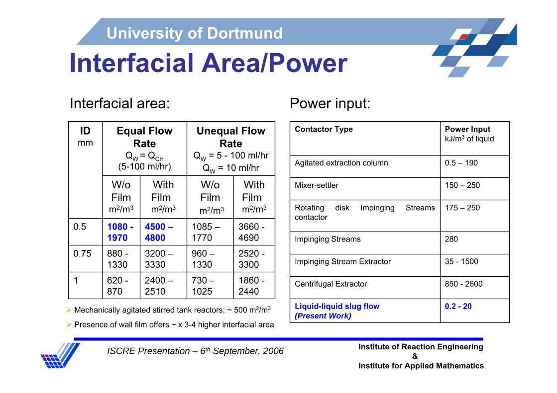
Interfacial Area/Power
1860 -2440
730 –1025
2400 –2510
620 -870
1
2520 -3300
960 –1330
3200 –3330
880 -1330
0.75
3660 -4690
1085 –1770
4500 –4800
1080 -1970
0.5
With Film , m2/m3
W/o Film m2/m3
With Film , m2/m3
W/o Film m2/m3
Unequal Flow Rate
QW = 5 - 100 ml/hr QW = 10 ml/hr
Equal Flow Rate
QW = QCH(5-100 ml/hr)
IDmm
Interfacial area:
Mechanically agitated stirred tank reactors: ~ 500 m2/m3
Presence of wall film offers ~ x 3-4 higher interfacial area
0.2 - 20Liquid-liquid slug flow (Present Work)
850 - 2600Centrifugal Extractor
35 - 1500Impinging Stream Extractor
280Impinging Streams
175 – 250Rotating disk Impinging Streams contactor
150 – 250Mixer-settler
0.5 – 190Agitated extraction column
Power InputkJ/m3 of liquid
Contactor Type
Power input:

ISCRE Presentation – 6th September, 2006 Institute of Reaction Engineering&
Institute for Applied Mathematics
University of Dortmund
Internal Circulations – PIV Experimentation
X-Y TranslationPlatform
ObjectCondenser
Exciter BlueFilter
540 nm
CCD camera
LabChip
ChromaticBeam Splitter
Fig.: Experimental set up
Experimental Snapshot
PIV velocity distributionWater (+ fluorescence) – paraffin oil, V = 0.031 mm/s

ISCRE Presentation – 6th September, 2006 Institute of Reaction Engineering&
Institute for Applied Mathematics
University of Dortmund
CFD SimulationsIncompressible Navier-Stokes equation
Boundary conditions
Numerical mesh
Solver2D, Projected solver, FEATFLOW
0; =∇=∇+Δ−∇⋅+∂∂ ufpuuu
tu υ
Moving Wall, Vwall = Vav
Stationay Interface,
Vint = 0
-0,375
-0,3
-0,225
-0,15
-0,075
0
0,075
0,15
0,225
0,3
0,375
-25 -20 -15 -10 -5 0 5 10 15 20
u-velocity [mm/s]
Rad
ius
of s
lug
[mm
]
Vav = 5.64 mm/s
Vav = 11.28 mm/s
Vav = 16.92 mm/s
Vav = 22.56 mm/s
r00
r0
Fig: Parabolic profiles in a slug
Fig: snapshot of CFD simulation

ISCRE Presentation – 6th September, 2006 Institute of Reaction Engineering&
Institute for Applied Mathematics
University of Dortmund
CFD - Recirculation TimeImportant parameter for Mass Transfer and MixingTime required for liquid particles to move from one end of the slug to the other end
( )( )
0
20
0
2nofilm r
av
L r
L U r r drV
τ =
∫
0
1
2
3
4
5
6
0 50 100 150 200 250
Flow Velocity [mm/s]
Circ
ulat
ion
Tim
e [-]
Phase 1 (L = 2.379 mm)Phase 1 (L = 4.758 mm)Phase 2 (L = 0.561 mm)Phase 2 (L = 1.122 mm)
0
1
2
3
4
5
6
0 50 100 150 200 250
Flow Velocity [mm/s]
Circ
ulat
ion
Tim
Phase 1 (L = 2.379 mm)
Phase 1 (L = 4.758 mm)
Phase 2 (L = 0.561 mm)
Phase 2 (L = 1.122 mm)
Fig: Recirculation time without film Fig: Recirculation time with film

ISCRE Presentation – 6th September, 2006 Institute of Reaction Engineering&
Institute for Applied Mathematics
University of Dortmund
CFD - Particle TracingMethod of visualizationConverts Eulerian description of a flow into Langragian description with selected particleIn-house developed algorithm, GMVPT
Phase 1 Phase 2L = 2.379 mm L = 1.12 mmD = 0.75 mm D = 0.75 mmVav = 5.64 mm/s Vav = 11.28 mm/s

ISCRE Presentation – 6th September, 2006 Institute of Reaction Engineering&
Institute for Applied Mathematics
University of Dortmund
Mass Transfer - Experimentation
0
0.02
0.04
0.06
0.08
0.1
0.12
0 0.04 0.08 0.12 0.16 0.2Slug flow velocity [m/s]
kLa
[s-1]
375 - 1120Water – succinic acid –n-butanol Present work
775 - 2500Water (c) – succinic acid –n-butanol (d)
1364 - 4456Kerosene – acetic acid – water (c)
1187 - 3975Water (c) – iodine – kerosene (d)Rotating disks impinging streams contactor
560 – 2000Water (c) – iodine – kerosene (d)
500 – 3000Kerosene (d) – acetic acid –water (c)
15 - 2100Water (c) –iodine – kerosene (d)Impinging streams
28.5Water (c) – acetaldehyde – vinyl acetate (d)Perforated plate column
7.4 -24CCl4 (c) – acetone – water (d)Packed column
8 - 60Water (c) –acetone –benzene (d)Spray column
0.15n-hexane(c) – acetone – water (d)Rotated agitated column
57Water (c) – succinic acid – n-butanol (d)Rotated disk contactor
0.16-16.6Water (c) -iodine-CCl4 (d)Agitated vessel
kLa x 104, s-1Chemical systemContactor
Fig.: Volumetric mass transfer coefficient Operating Conditions:
0.5, 0.75 and 1 Y-junction ID, mm
0.5, 0.75 and 1 Capillary ID, mm
Slug flow regimeRegime
Water – succinic acid –n-butanolSystem
ISCRE Presentation – 6th September, 2006 Institute of Reaction Engineering&
Institute for Applied Mathematics
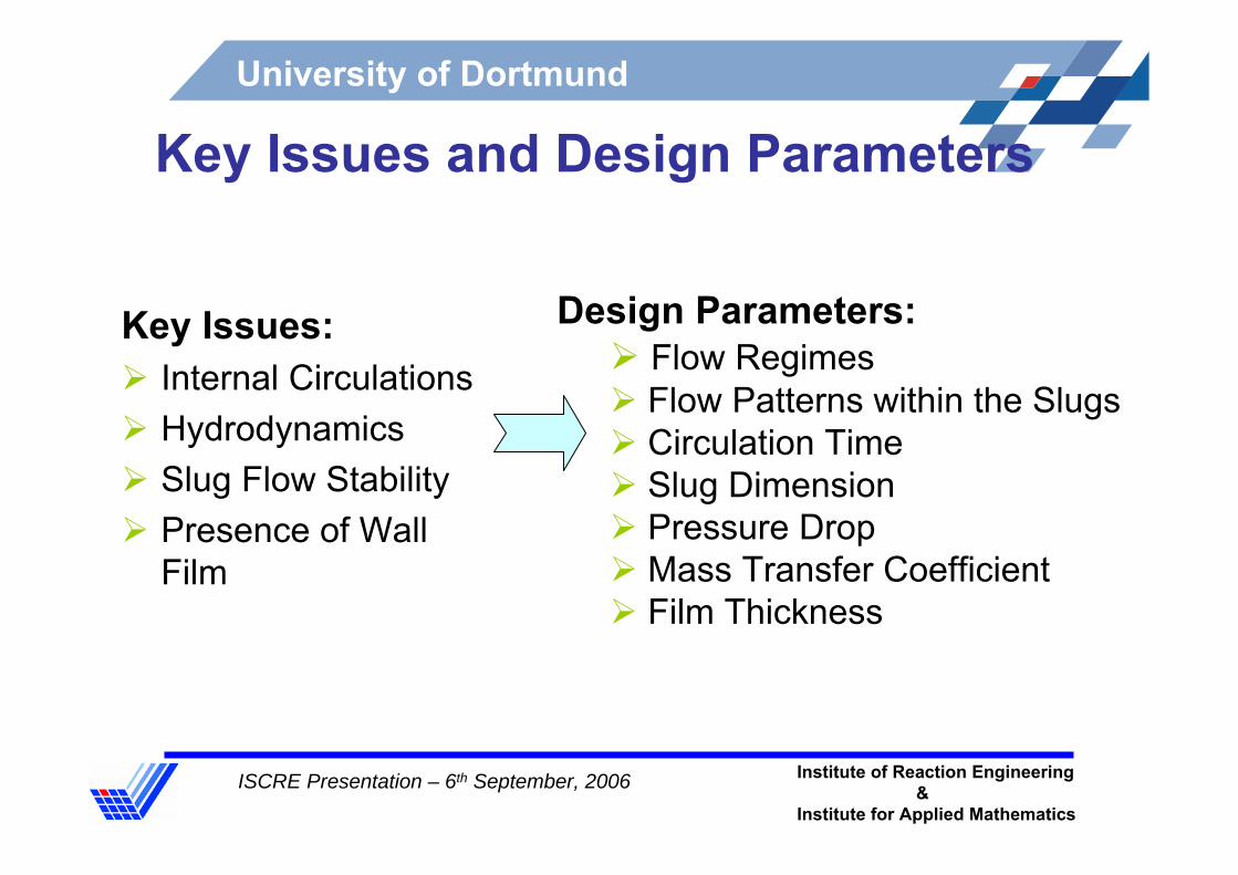
University of Dortmund
Key Issues and Design Parameters
Key Issues:Internal CirculationsHydrodynamics Slug Flow StabilityPresence of Wall Film
Design Parameters:Flow Regimes Flow Patterns within the SlugsCirculation TimeSlug DimensionPressure DropMass Transfer CoefficientFilm Thickness

ISCRE Presentation – 6th September, 2006 Institute of Reaction Engineering&
Institute for Applied Mathematics
University of Dortmund
Hydrophobic wall preferentially wetted by organic phase
Experimentally observed transition behaviour ~ 10 mm
Film thickness (Bretherton Law):
Enhanced interfacial area:
Slug & average flow velocity:
Film not stagnant:
2 31.34h RCa=
2
21 ( )s av
s
V VR R
=+
av film slugQ Q Q= +
π
π
≅
⎡ ⎤= − +⎣ ⎦
2
2
WithoutFilm: 2
WithFilm: 2 ( ) Where,r = Radius of capillary
a r
a r h rl
Wall Film

ISCRE Presentation – 6th September, 2006 Institute of Reaction Engineering&
Institute for Applied Mathematics
University of Dortmund
Introduction - Liquid-liquid contacting
Suspended drop contactors– Difficult to control drop size conditioning– Scale-up is difficult– Efficiency diminishes at low solvent/feed ratio
Film contactors– Ability to optimise solvent/feed ratio