cfd-modeling of a flow in a hydrocyclone with an additional water
TRANSCRIPT

КОМПЬЮТЕРНЫЕ ИССЛЕДОВАНИЯ И МОДЕЛИРОВАНИЕ 2011 Т. 3 № 1 С. 63−76
МОДЕЛИ В ФИЗИКЕ И ТЕХНОЛОГИИ
УДК: 532.542.4:575.5, 519.63
CFD-modeling of a flow in a hydrocyclone with an additional water injector
L. Minkov1, a, J. Dueck2
1 Tomsk State University, Department of Physics and Engineering
Lenin av., 36, Tomsk, 634050, Russia 2 Friedrich-Alexander-University, Erlangen-Nuremberg LUR, Paul-Gordan str. 3, Erlangen, D-91052, Germany
E-mail: a [email protected]
Получено 24 февраля 2011 г.
Abstract. – The paper is an example of computer simulation in mechanical engineering. Velocity field in
a hydrocyclone are determined numerically, because for direct measurements it is difficult to achieve them. The numerical simulation of 3D fluid dynamics based on the k-eps RNG model of turbulence in the hydrocyclone with the injector, containing 5 tangentially directed nozzles is considered. It is shown that the direction of movement of injected fluid in the hydrocyclone depends on the water flow rate through the injector. The calculations show in accordance with the experiments that the dependence of the Split-parameter on the injected water flow rate has a non-monotone character associated with the ratio of power of the main flow and the injected fluid.
Keywords: hydrocyclone, injection, computational fluid dynamics
Моделирование течения в гидроциклоне с дополнительным инжектором
Л. Л. Миньков1,a, И. Г. Дик2
1 Томский государственный университет, физико-технический факультет, Россия, 634050, г. Томск, пр. Ленина, 36 2 Университет Эрланген-Нюрнберг, Германия, D-91052, г. Эрланген, ул. Пауля Гордона, 3 Статья представляет собой пример компьютерного моделирования в области инженерной механики. Числен-ным методом находятся поля скорости в гидроциклоне, которые недоступны прямому измерению. Рассмат-ривается численное моделирование трехмерной гидродинамики на основе k-ε RNG модели турбулентности в гидроциклоне со встроенным инжектором, содержащим 5 тангенциально направленных сопла. Показано, что направление движения инжектируемой жидкости зависит от расхода жидкости через инжектор. Расчеты показывают в соответствии с экспериментами, что зависимость сплит-параметра от расхода инжектируемой жидкости имеет немонотонный характер, связанный с отношением мощности основного потока и инжекти-руемой жидкости.
Ключевые слова: гидроциклон, инжекция, вычислительная гидродинамика Citation: Computer Research and Modeling, 2011, vol. 3, no. 1, pp. 63–76
© 2011 Леонид Леонидович Миньков, Johann Dueck
L. Minkov, J. Dueck
____________________ КОМПЬЮТЕРНЫЕ ИССЛЕДОВАНИЯ И МОДЕЛИРОВАНИЕ ____________________
64
Introduction
Hydrocyclones are widely used in different fields of engineering applications. Feed slurry is in-troduced under pressure tangentially into the apparatus. This creates the centrifugal force and the flux of particles toward the wall, thus leading to phase separation.
In spite of its simple configuration, the hydrocyclone has a complex flow field: very strong circulation, complex turbulent fields, formation of closed circulation zones, and formation of the air core near the central axis zone. Turbulent diffusion prevents fine particles to accumulate near the wall of hydrocyclone and even leads to make them spreads over the whole space of the hydro-cyclone.
Many publications [Pericleous K. A., Rhodes N.,1986; Davidson M. R.,1988; Hsien K. T., Raja-mani R. K., 1991; Monredon T. C. et al, 1992; Dyakowski T., Williams R. A.,1993; He P. et al, 1999; Dai G. Q. et al, 1999; Novakowski A. F. et al, 2000; Ko J. et al, 2006] were devoted to the theory of hydrocyclone hydrodynamics (computational mathematics) while other were focusing on the techno-logical aspects of the solid-liquid separation or size classification [Nowakowski A. F. et al, 2004; Dueck J. et al, 2000; Narasimha M. et al, 2005; Schütz S. et al, 2007; Neesse T., Dueck J., 2007].
The typical disadvantages of hydrocyclone operation can be summarized as follows: incomplete separation of solid phase especially the fine fractions, insufficient quality of the separation, and the relatively small value of cut size. These disadvantages can be partially eliminated by changing the de-sign parameters of the hydrocyclone.
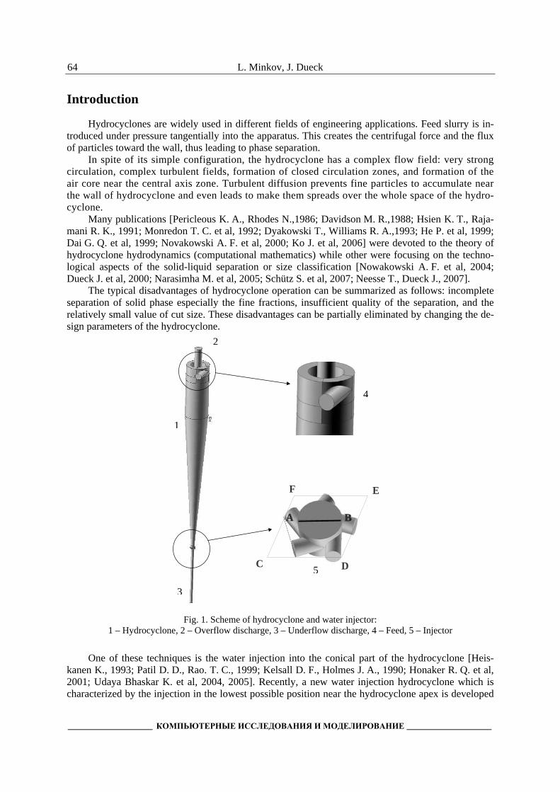
Fig. 1. Scheme of hydrocyclone and water injector: 1 – Hydrocyclone, 2 – Overflow discharge, 3 – Underflow discharge, 4 – Feed, 5 – Injector
One of these techniques is the water injection into the conical part of the hydrocyclone [Heis-kanen K., 1993; Patil D. D., Rao. T. C., 1999; Kelsall D. F., Holmes J. A., 1990; Honaker R. Q. et al, 2001; Udaya Bhaskar K. et al, 2004, 2005]. Recently, a new water injection hydrocyclone which is characterized by the injection in the lowest possible position near the hydrocyclone apex is developed
A B
C D
E F
A B
1
2
5
3
4

CFD-modeling of a flow in a hydrocyclone with an additional water injector
_______________________________________ 2011, Т. 3, № 1, С. 63–76_______________________________________
65
and is schematically shown in Fig.1. A simplified mathematical model of classification in a hydrocyc-lone is presented in [Dueck J. G. et al., 2009]. Further development requires a deep knowledge of hy-drodynamics in the hydrocyclone with the injector.
Water injection is expected to wash out the fine particles from the wall boundary layer to the axis where particles are swept up by upward flow and then discharge through the overflow.
Thus the undesirable removal of small particles through the underflow can be reduced. The effect of the injection depends on many parameters such as: the amount of injected water, the
injection rate, the location of injection and many other parameters which should be optimised. In addition to experimental investigations, the modelling of the injection is of great importance to understand the injection mechanism. Models describing the influence of water injection on the separa-tion efficiency of dispersed material are still lacking in the literature. Such models can be created on the basis of relevant studies of hydrodynamics. It is the aim of this work. Particular attention was fo-cused on the explanation of the effect of the injection on the change of flow field, and hence on the classification mechanisms.
Difficulties in the mathematical formulation of the hydrodynamic problem arise in the formula-tion of boundary conditions for the both outlets and the description of the turbulent flow regime in the apparatus. In particular, the choice of turbulence model is important. In this paper, based on previous experience [Dueck J. et al, 2000], we used a traditional ε−k –RNG model of turbulence, which com-bines the simplicity and sufficient accuracy for further analysis.
Numerical model
The geometry of the hydrocyclone is given in Fig. 2.
dinj hinj
z = 0
hinj dinj
Dc 50 mm
Din 14.5 mm
Do 16 mm
Du 6 mm
L1 130 mm
L2 350 mm
L3 135 mm
l1 + l2 79 mm
l2 37 mm
l 8 mm
dinj 2.5 mm
hinj 20 mm
Fig. 2. Geometry and 3D grid of water injection hydrocyclone
The grid for a discrete description of flow field was realized with the help of a computer soft-ware (Gambit 2.3.16., Fluent Inc. ©) to create the 3D body fitted grid of 170000 cells. Tetrahedron
L. Minkov, J. Dueck
____________________ КОМПЬЮТЕРНЫЕ ИССЛЕДОВАНИЯ И МОДЕЛИРОВАНИЕ ____________________
66
grid was used to fit inlet regions and hexahedron one – to fit other regions, Fig.2. Calculation of hy-drodynamics was done on the base of Fluent 6.3.26 software.
The set of Navier-Stokes equations includes:
• Continuity equation 0=∂∂
i
i
x
u, 3,2,1=i .
• Momentum equation ⎟⎟
⎠
⎞
⎜⎜
⎝
⎛
∂∂
∂∂=
∂∂+
∂∂
j
ieff
jij
ji
x
u
xx
p
x
uuμ , 3,2,1, =ji .
The RNG ε−k model of turbulence [Yakhot V. et al, 1992] is used to calculate effective viscosity
tmoleff μμμ +=
• The turbulence kinetic energy equation ρεμαρ−+
⎟⎟
⎠
⎞
⎜⎜
⎝
⎛
∂∂
∂∂=
∂∂
k
j
effk
ji
i Gx
k
xx
ku.
• The dissipation rate of turbulence kinetic energy equation
( )ρεεεμαρεεεε 21 CGC
kxxx
uk
j
eff
ji
i −+⎟⎟
⎠
⎞
⎜⎜
⎝
⎛
∂∂
∂∂=
∂∂
.
Knowing values of the turbulence kinetic energy and its dissipation rate one can calculate the value of turbulent viscosity as follows:
⎟⎠
⎞⎜⎝
⎛ Ω=ε
αε
ρμ μk
fk
C st ,,2
,
Where:
⎟⎠
⎞⎜⎝
⎛ Ωε
α kf s ,, – the correction function taking into account a swirling flow [FLUENT 6.3 User's Guide.
Fluent Inc. 2006-09-20. – 2006]. 2SG tk μ= ; ijijSSS 2≡ .
Where:
ijS – mean rate-of-strain tensor⎟⎟
⎠
⎞
⎜⎜
⎝
⎛
∂∂+
∂∂
=j
i
i
j
x
u
x
u
2
1
( )3
03
22 1
1
βηηηημ
ε +−
+=C
CC .
Where:
εη k
S≡ .
Model constants:
393.1≈= εαα k ; 15.0=sα ; 012.0=β ;
42.11 =εC ; 0845.0=μC ; 38.40 =η .
Boundary conditions: a) At the inlet of main feed pipe.
Normal component of inlet velocity: 2
4
inlet
inletn D
Qu
π= .

CFD-modeling of a flow in a hydrocyclone with an additional water injector
_______________________________________ 2011, Т. 3, № 1, С. 63–76_______________________________________
67
Tangent component of inlet velocity: 0=τu .
Turbulence kinetic energy: ( )22102
3nuk −= .
Dissipation rate of turbulence kinetic energy: inletD
kC
07.0
2/34/3
με = .
Where:
inletD – diameter of feed pipe,
inletQ – volumetric flow rate at the inlet of main feed pipe. b) At the inlet of injector feed pipe:
Normal component of injection velocity 2
4
inj
injn d
Qu
π= .
Tangent component of inlet velocity 0=τu .
Turbulence kinetic energy ( )22102
3nuk −= .
Dissipation rate of turbulence kinetic energy injd
kC
07.0
2/34/3
με = .
Where:
injd – diameter of injector pipe,
injQ – volumetric flow rate at the inlet of injector pipe.
c) On the injector and hydrocyclone walls: No-slip conditions were chosen 0=iu . d) At the outlets: The ambient pressure was applied in the centre of the upper flow and underflow outlets and the condi-tion of equilibrium of the centrifugal forces with the radial pressure gradient was used in the internal points of the outlets:
r
u
r
p 2τρ
=∂∂
.
The set of equations (1)–(4) was numerically solved using the upwind differential scheme of sec-ond order of accuracy for convective terms and the second order of accuracy for pressure gradients. SIMPLEC was used for the pressure-velocity coupling.
Results and Discussion
The main interest in the calculations consists in obtaining information inaccessible in the experiments. These include primarily the velocity field in the device, which allows the understanding the effects that occur from the additional water injection. These characteristics will be discussed later.
Confidence in the reliability theory can be achieved by matching calculations and measurements, where possible. Therefore, it is important to compare the throughput characteristics at different operation modes. The values of the flows through the discharge nozzles have also a practical significance.
Ratio of flow rates at outlets
The split-parameter (S), which is defined as the ratio of water flows through both output openings of apparatus (overflow and underflow water) is of great importance to the separation process and can
be given as follows: un
ov
Q
QS = .

L. Minkov, J. Dueck
____________________ КОМПЬЮТЕРНЫЕ ИССЛЕДОВАНИЯ И МОДЕЛИРОВАНИЕ ____________________
68
Fig. 3 shows the change of the split parameter related to throughput of the injected water ( injQ ) at
different feed pressure values. From this figure, it can be seen that the estimated numerical values of the split parameter ( )injQS
are agreed qualitatively well with the experimental data. The split parameter ( )injQS decreases gradu-
ally by increasing injQ in a small range. Further increase of injQ leads to gradually increase of the
split-parameter ( )injQS values. So, it can be concluded that the trend of the split-parameter curve as
a dependent on injQ is non monotone.
The results obtained in the calculation of the dependence agrees fairly well with experiments, so there is every reason to trust and further calculations of velocity fields
Fig. 3. Effect of the injection throughput on the split parameter
Stream lines and velocity fields
The flow field of fluid in the conical part of hydrocyclone on the section included the axis of cy-clone and the straight line AB is showed in Fig. 1 above the injector and is depicted in Fig. 4 (y = 0, z = –0.341 m). It should be noted, that using of 5 injectors tubes leads to asymmetrical profiles of ve-locities.
In the calculations, and the subsequent presentation of the results a rectangular coordinate system was used. Coordinate x is measured along the line AB as shown in Fig. 1 and the coordinate z is measured along the axis of the hydrocyclone, beginning with the transition cross section of the cylin-drical part of the hydrocyclone in a conical one, as shown in Fig. 1.
In case of no injection, the increased velocity zone directed to the apex takes place near the ax-ial domain (Fig. 4а). The velocity profile at low values of injection rate (Qinj = 4 lpm) becomes flat (Fig. 4b) whereas at high values of injection rate (Qinj = 9 lpm) the reorganization of flow field takes place near the wall of hydrocyclone, zones of flow inverse directed to the main one are formed (Fig. 4b).

CFD-modeling of a flow in a hydrocyclone with an additional water injector
_______________________________________ 2011, Т. 3, № 1, С. 63–76_______________________________________
69
а)
b)
c) Fig. 4. Flow fields above the injector (z = - 0.341 m).
Qfeed= 63.62 l/min. а) Qinj= 0 l/min; b) Qinj= 4 l/min;, c) Qinj= 9 l/min
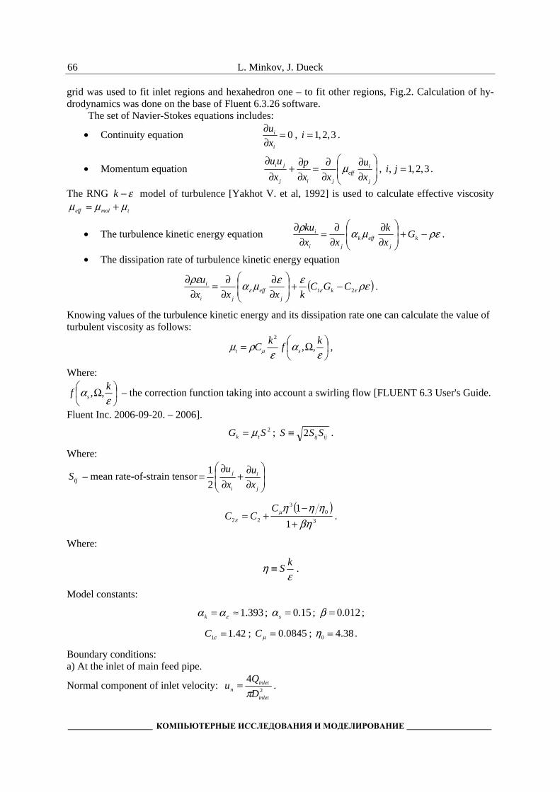
Similar conclusions can be made by analysis of Fig. 5. Fig. 5 shows the swirling trajectories of the injected liquid for nonzero rates: 4 lpm, (Fig. 5 a) and
9 lpm, (Fig. 5 b and Fig. 5 c). At low injection rate (Qinj = 4 lpm) most of the injected water is en-trained by the main flow and leaves the hydrocyclone through the underflow which leads to the in-creasing the water discharge through the underflow.
y
x
–12.69 mm
–94.69 mm
–176.69 mm
–258.69 mm
–340.69 mm
–12.69 mm
–94.69 mm
–176.69 mm
–258.69 mm
–340.69 mm
–12.69 mm
–94.69 mm
–176.69 mm
–258.69 mm
–340.69 mm
6 m/s
x
y
y
x
2 m/s
6 m/s
L. Minkov, J. Dueck
____________________ КОМПЬЮТЕРНЫЕ ИССЛЕДОВАНИЯ И МОДЕЛИРОВАНИЕ ____________________
70
а) b) c)
Fig.5. Trajectories of fluid. Qfeed = 63.62 l/min. а) Qinj = 0 l/min; b) Qinj = 4 l/min; c) Qinj = 9 l/min 1 – Trajectory of fluid particle leaving the hydrocyclone through the upper outlet 2 – Trajectory of fluid particle leaving the hydrocyclone through the down outlet
At high injection rate (Qinj = 9 lpm) in Fig. 5b one can see the trajectories of injected fluid are both upward and downward. This means that the injected liquid can be entrained by two streams and can be re-moved from the apparatus through the both outlets. It is interesting to note that at this injection intensity (Qinj = 9 lpm) among trajectories initially directed upwards, there are those which at a certain height relative to the injector are fully turned and finish at the underflow apex (Fig. 5c, trajectory 2).
Velocity components
The following results were picked up on the section included the axis of apparatus and the straight line AB, showed in Fig. 1. Along this line is the x-coordinate, which intersected with the axis of apparatus (axis of hydrocyclone).
1
2
2 2
2

CFD-modeling of a flow in a hydrocyclone with an additional water injector
_______________________________________ 2011, Т. 3, № 1, С. 63–76_______________________________________
71
Axial velocity
The profiles of the axial velocity are shown in Fig. 6. The axial velocity above the position of the injector is shown in Fig. 6a while the axial velocity under the position of the injector is shown in Fig. 6b.
At low injection rate the power of injected water is small to overcome the resistance of the main flow. Additional resistance created by the injected water results in the stagnation of main flow near the injector. All flux from the injector directs to the underflow that leads to the increase in the axial veloc-ity of flow into the apex.
At injection with flow rate equal to 4 lpm, all the liquid flowing through the inlet, leaves the hy-drocyclone either through the overflow or through the underflow, while the injected liquid flows only through the underflow. When Qinj = 9 lpm, the power of injected jet is enough to overcome the resis-tance of the main flow and the injected liquid flows both through the underflow and through the over-flow while the liquid fed through the inlet flows through the underflow discharge.
At high injection rate the upward swirling flow along the wall of cone part of hydrocyclone is formed upstream. At the zone near the axis the downward swirl rotating co-axial with the outer vortex is developed.
The three minima presented in the velocity distribution in Fig. 6b can be explained by the pres-ence of two whirls present in this part of the apparatus; one is formed on the periphery as a result of the liquid which comes directly from the injector to the apex, the other central whirl formed by a liq-uid which is carried away from the injector upwards which is braked as a result of interaction with the main downwards stream.
Fig. 6. Dependence of axial velocity distribution of a transverse coordi-nates x at various velocities of injected water Qinj. a) Z = −0.341 m (above the injector position); b) Z = −0.350 m (under the injectors position)

L. Minkov, J. Dueck
____________________ КОМПЬЮТЕРНЫЕ ИССЛЕДОВАНИЯ И МОДЕЛИРОВАНИЕ ____________________
72
Tangential velocity
Fig. 7 shows the distribution of the tangential velocity. This velocity component, as a source of centrifugal force, affects critically the classification performance.
In Fig. 7a mild injection leads to a reduction in the tangential velocity on the periphery of liquid (at 4 lpm). Increasing of the injected velocity leads to an increase in the tangential component of flow. Thus the tangential velocity increases in the whole flow (at 9 lpm). Near the axis zone the velocity distribution of rotating flow is similar to the velocity distribution of a solid body (profiles tangential velocities are close to straight lines). Towards the periphery, the velocities profiles change the sign of their second derivative, which showed, as stated previously, the existence of internal injector swirl rotating at a velocity different from the velocity of the external vortex.
Fig. 7b shows the tangential velocity profiles at the position under the injectors at different veloc-ity of injected water. At low injection velocity of 4 lpm, only weak changes are occurred at the profile tangential speed below the injector, while at high injection speed of 9 lpm the velocity of the flow near the wall of apex is increased.
Fig. 7. Profiles of tangential velocity: a) above the injector (Z = −0.341 mm); b) below the injector (Z = −0.350 mm)
Radial velocity
A strong restructuring of the profile of the radial velocity occurs above the injector (Fig. 8a). In case of no injection, the fluid is directed from the axis to the walls (solid curve at Qinj = 0). The
curves are rather symmetrical relatively to the z-axis. The positive values of radial velocity at x > 0 indicate the movement from the axis to the wall, as negative for x < 0. The low injection velocity re-

CFD-modeling of a flow in a hydrocyclone with an additional water injector
_______________________________________ 2011, Т. 3, № 1, С. 63–76_______________________________________
73
duces the radial velocity and changes its direction to the opposite from the periphery to the center (the curve at Qinj = 4 lpm). At high injection rates there is a non monotone and asymmetrical profile of radial velocity (curve at Qinj =4 lpm). Near the axis the flow is directed to the periphery of the axis, while near to the walls the motion may be directed inward (the left part profile) and outside (the right side profile). Under the injector (Fig. 8b) the radial velocity is directed mostly to the wall. The radial velocity is rather weaker in comparison with the case without injection.
Fig. 8. Profiles of radial velocity: a) over the injector (Z = −0.341 m); b) under the injector (Z = −0.350 m); Arrows indicate the direction of the radial velocity at 9.0 lpm
Discussion Injection of water through the hydrocyclone may significantly change the hydrodynamic field in
the apparatus. This change is particularly strong near the injection inlets. The present work examined the impact of tangential injection of water through the injector, located at the bottom of the conical part of the hydrocyclone. The influence of tangential injection is found to be the highest hydrodynamic impact on the separation and the classification processes.
Although the solid phase is not included directly in the description, nevertheless analysis of the hydrodynamic field allows understanding the mechanisms of injection in the apparatus of separation processes.
L. Minkov, J. Dueck
____________________ КОМПЬЮТЕРНЫЕ ИССЛЕДОВАНИЯ И МОДЕЛИРОВАНИЕ ____________________
74
The calculation results showed that the injection influence can occur not only due to the change of radial velocity component, as it was supposed, i.e. carrying out the particles from near the wall zone into the axis region and then to be separated in the overflow outlet. This can be shown apparently from Fig. 8, where the radial velocity changes its sign (radial speed changes its direction) at intervals along radial coordinate from the axis towards the wall.
The other reason which could be more possible to explain the injection effect is by considering the mechanism influencing the particles (if they would be in a flow), that is connected with the change of the axial component as follows:
A powerful stream of liquid arises upward during enough strong injection at the conical wall of the hydrocyclone, should move out the particles upwards specially the fines up to the cylindrical part of the cyclone. Some of these particles which follow the flow lines as it is shown in Fig. 5, will be di-rected to the overflow, another will return downwards again and be compelled to undergo again through the hydrodynamic influence of injector.
Apparently, the probability of such particles to be transported through the underflow discharge is much lower in comparison with similar probability for particles, which do not be influenced by in-jected jets.
This circumstance well proves to be true in experiments [Heiskanen K., 1993; Patil D. D., Rao T. C., 1999; Kelsall D. F., 1990; Honaker R. Q. et al 2001; Udaya Bhaskar K. et al, 2004, 2005], where significant decrease of values of the separation function (analogue of discussed probability of carrying out the particles through the apex) for fine particles was observed.
Concerning the effect of the tangential velocity, the results have showed that the increase of in-jection throughput leads to a growth in the centrifugal force (tangential velocity component). This force affects on the particles and brings them out towards the hydrocyclone wall. It is known that the larger are the particles the higher is the effect. Thus for fine particles the increase in tangential velocity practically will not cause any effect, while the coarse particles should leave more effectively to a wall, and, finally, to apex.
The presented calculations show, that the influence of injection on the flow in the hydrocyclone is af-fected by alteration the velocity field by injected water. At low water injection rate, the injected tangential water slows the mean stream, especially its tangential component (Fig. 7), but at high injection speed, it accelerates the tangential component. The character of the injection influence on the hydrodynamics of the flow determines the injected water ratio between both outlets (overflow and underflow).
Computations show in addition to the experiments a non monotonous change in the ratio of the injected water through the underflow. This explains the change of the influence mechanism of the in-jected water on the main flow.
Conclusions
Application of numerical methods to analyze engineering problems brings tangible benefits where direct measurement is difficult or too expensive. An example of such applications is the problem of flow in a hydrocyclone of a special type, equipped with an injector device allowing substantially affect the performance of separation.
The influence of tangential water injection through an injector, located at the conical part just above the apex, on the mean stream in a hydrocyclone is investigated. The injection of water in a hydrocyclone can markedly change the hydrodynamic fields in the device.
On the basis of the calculations partially supported by measurements, the mechanism of the injec-tion influence on separation characteristics of the hydrocyclone is explained.
The mechanism is based on the generation of the axial streams which have been directed upwards that leads the recirculation of particles in the device and to lowering the value of probability for fine particles to be transported through the underflow discharge.
At low water injected rates, the mean stream is broken, but at high ones it is accelerated. It leads to non monotone dependence of a fraction of the injected water allocated through the underflow aperture.
CFD-modeling of a flow in a hydrocyclone with an additional water injector
_______________________________________ 2011, Т. 3, № 1, С. 63–76_______________________________________
75
References
Dai G. Q., Li J. M., Chen W. M. Numerical prediction of the liquid flow within a hydrocyclone // Chem. Eng. J. – 1999. – 74. – P. 217–223.
Davidson M. R. Simularity solution for flow in hydrocyclones // Chem. Eng. Sci. 1988. 43 (7). P. 1499–1505. Dueck J., Matvienko O. V., Neesse Th. Modeling of Hydrodynamics and Separation in a Hydrocyclone //
Theoretical Foundation of Chemical Engineering. – 2000. – 34, No. 5. – P. 428–438. Dueck J. G., Pikushchak E. V. and Minkov L. L. Modelling of change of the classifiers separation character-
istics by water injection into the apparatus // Thermophysics and Aeromechanics. – 2009. – 16, No. 2. – P. 247–258.
Dyakowski T., Williams R. A. Modelling turbulent flow within a small-diameter hydrocyclone // Chem. Eng. Sci. – 1993. – 48 (6). – P. 1143–1152.
He P., Salcudean M., Gartshore I. S. A numerical simulation of hydrocyclones // Trans. Inst. Chem. Eng. J. Part A. – 1999. – 7. – P. 429–441.
Heiskanen K. Particle Classification. London–Glasgow–New York–Tokyo–Melbourne–Madras: Chapman and Hall, 1993. – 321 p.
Honaker R. Q., Ozsever A. V., Singh N., Parekh B. K. Apex water Injection for improved hydrocyclone classification efficiency // Mineral Engineeering. – 2001. – 14, No. 11. – P. 1445–1457.
Hsien K. T., Rajamani R.K. Mathematical model of the hydrocyclone based of fluid flow // AIChE J. – 1991. – 37 (5). – P. 735–746.
Kelsall D. F., Holmes J. A. Improvement in classification efficiency in hydraulic cyclones by water injec-tion. In. Proc. 5th Mineral processing Congress, Paper 9, Inst. Of Mining and Metallurgy. 1990. – P. 159–170.
Ko J., Zahrai S., Macchion O., Vomhoff H. Numerical modeling of highly swirling flows in a through-flow cylindrical hydrocyclone // AIChE Journal. – 2006. – 52, 10. – P. 3334–3344.
Monredon T. C., Hsien K. T., Rajamani R. K. Fluid flow model of the hydrocyclone: an investigation of device dimensions // International Journal of Mineral Processing. – 1992. – 35. – P. 65–83.
Narasimha M. Sripriya R., Banerjee P. K. CFD modelling of hydrocyclone- prediction of cut size // Inter-national Journal of Mineral Processing. – 2005. – 75. – P. 53–68.
Neesse T. and Dueck J. CFD – basierte Modellierung der Hydrozyklonklassierung // Chemie Ingenieur Technik. – 2007. – 79, 11. – P. 1931–1938.
Neesse T., Dueck J. Dynamic modelling of the hydrocyclone // Minerals Engineering. – 2007. – 20. – P. 380–386.
Novakowski A. F., Kraipech W., Dyakowski T., Williams R. A. The hydrodynamics of a hydrocyclone based on a three-dimensional multi-continuum model // Chem. Eng. J. – 2000. – 80. – P. 275–282.
Nowakowski A. F., Cullivan J. C., Williams R. A., Dyakowski T. Application of CFD to modelling of the flow in hydrocyclones. Is this a realizable option or still a research challenge? // Minerals Engi-neering. – 2004. – 17. Issue 5. – P. 661–669.
Patil D. D., Rao. T. C. Technical Note. Classification evaluation of water injected hydrocyclone // Mineral Engineering. – 1999. – 12, 12. – P. 1527–1532.
Pericleous K. A., Rhodes N. The hydrocyclone classifier – a numerical approach International // Journal of Mineral Processing. – 1986. – 56. – P. 23–43.
Schütz S., Piesche M., Gorbach G., Schiling M., Seyfert C., Kopf P., Deuschle T., Sautter N., Popp E., Warth T. CFD in der mechanischen Trenntechnik // Chemie Ingenieur Technik. – 2007. – 79, 11. –P. 1777–1796.
Udaya Bhaskar K., Govindarajan B., Barnawal J. P., Rao K. K., Gupta B. K., Rao T. C. Classification studies of lead-zinc ore fines using water-injection cyclone // Intern. Journ. Mineral Processing. – 2005. – 77. – P. 80–94.

L. Minkov, J. Dueck
____________________ КОМПЬЮТЕРНЫЕ ИССЛЕДОВАНИЯ И МОДЕЛИРОВАНИЕ ____________________
76
Udaya Bhaskar K., Govindarajan B., Barnawal J. P., Rao K. K., Rao T. C. Modelling studies on a 100 mm water-injection cyclone // Physical Separation in Science and Engineering, September-December. – 2004. – 13. No. 3–4. – P. 89–99.
Yakhot V., Orszag S. A., Thangam S., Gatski T. B., Speziale C. G. Development of turbulence models for shear flows by a double expansion technique // Physics of Fluids A. – 1992. – 4. No. 7. – P. 1510–1520.