cf500/cf500 a
TRANSCRIPT
CF500/CF500-A
2006 By Chunfeng Holding Group Co. Ltd.
First Edition, August 2006
All Rights Reserved Any reproduction or unauthorized use of this manual
without written permission of CFMOTO is extremely prohibited

FOREWORD INDEX This manual contains an introductory description of procedures for inspection , maintenance, overhaul,disassembly & assembly,removal and installation of components and parts, troubleshooting and service data together with illustrations of our All Terrain Vehicle Model CF500 and CF500-A Chapter 1:general service information, tools,vehicle structure and technical data. Chapter3: key points for inspection and adjusting,service guide. Chapter 2 and after Chapter 3:disassembly of parts and components,installation,overhaul and troubleshooting. The manufacturer reserves the right to make improvements or modifications to the products without prior notice. Overhaul and maintenance should be done according to the actual state and condition of the ATV.
Vehicle Service Information 1 Vehicle Body、Muffler 2 Inspection & Adjustment 3 Cooling System 4 Removal and Installation of Engine, Drive Train and Gearshift Unit
5
Front Wheel, Front Brake, Suspension, Steering
6
Rear Wheel, Rear Brake, Suspension 7 Battery, Charging System 8 Ignition System 9 Lighting, Instruments & Switches 10Circuit Diagram、Wiring Diagram 11Troubleshooting 12Engine Engine Overhaul Information 13Checks & Maintenance 14Engine Removal, Inspection and Installation
15
Carburetor 16Cooling and Lubrication System 17Electrical System 18Troubleshooting 19

Conversion Table
Item Example Conversion Pressure 200Kpa (2.00kgf/cm2)
33kpa(250mmHg) 1kgf/cm2=98.0665kpa 1kpa=1000pa 1mmHg=133.322Pa=0.133322Kps
Torque 18N·m(1.8kgf-m) 1kgf· m=9.80665N·m Volume 419ml 1ml=1cm3=1cc
1l=1000cm3 Force 12N (1.2kgf) 1kgf=9.80665N
1. Overhaul Information
Cautions…………………………………… 1-1 Tightening Torque……………….1-10 VIN Number & Engine Number………….…..1-4 Lubricant, Sealing Agent………..1-11 Main Data Table…………………..……… ..1-5 Cable Routing…………………...1-12 Overhaul Data Table………………………..…1-6 Cautions Safety Cautions 1. Hazardous components in exhaust. Do not run the engine in a enclosed or poorly ventilated
place for long time. 2. Do not touch the engine or muffler with bare hands after the engine has just stopped to avoid
scalding. Wear long-sleeve work clothes and gloves for operation.
3. Battery liquid (dilute sulfuric acid) is highly caustic and may cause burns to skin and eyes. Flush with water if splashed to skin and get immediate medical attention. Flush with water if splashed to clothes to avoid burns. Keep battery and liquid away from reach of children
4. Coolant is poisonous. Do not drink or splash to skin, eyes or clothes. Flush with plenty of soap
water if splashed to skin. If splashed into eyes, flush with water and consult the doctor. If drinking the coolant, induce vomit and consult the doctor. Keep coolant away from reach of children.
5. Wear proper work clothes, cap and boots. If necessary, were dust-glass, gloves and mask. 6. Gasoline is highly flammable. No smoking or fire. Also keep against sparks. Vaporized
gasoline is also explosive. Operate in a well-ventilated place. 7. When charged, Battery may generate hydrogen which is explosive. Charge the battery in a
well-ventilated place. 8. Be careful not to get clamped by the turning parts like wheels and clutch. 9. When more than two people are operating, keep reminding each other for safety
purpose. Cautions for Disassembling and Assembling 1. Use genuine CFMOTO parts, lubricants and grease
2. Clean the mud, dust before overhauling
3. Store the disassembled parts separately in order for correct assemble.
4. Replace the disassembled washers, o-rings, piston pin retainer, cotter pin with new ones.
5. Elastic retainers might get distorted after disassembled. Do not use the loosened retainers.
1-1
1. Overhaul Information
6. Clean and blow off the detergent after disassembling the parts. Apply lubricants on the
surface of moving parts. Measure the data during disassembly for correct assembling.
7. If you do not know the length of screws, install the screws one by one and make sure they
are screwed in with same depth.
8. Pre-tighten the bolts, nuts and screws, then tighten according to the specified torque,
from big to small and from inner side to outer side.
9. Check if the disassembled rubber parts are aged and replace if necessary. Keep the
rubber parts away from grease.
10. Apply or inject recommended lubricant to the specified parts.
11. Use special tools wherever necessary.
12. Replace the disassembled ball bearings with new ones.
13. Turn the inner and outer rings of ball bearing to make sure the bearing will turn smoothly.
Replace if the axial or radial play is too big. If the surface is uneven, clean with oil and
replace if the cleaning does not help.
When pressing the bearing into the machine or to the shaft, replace the bearing if it could not
be pressed tight.
14. Install the one-side dust-proof bearing in the right direction. When assembling the open
type or double-side dustproof bearing, install with manufacturer’s mark outward.
15. Keep the bearing block still when blowing dry the bearing after washing clean. Apply
oil or lubricant before assembling.
16. Install the elastic circlip properly. Turn the circlip after assembling to make sure is has been
installed into the slot.
17. After assembling, check if all the tightened parts are properly tightened and can move
smoothly.
18. Brake fluid and coolant may damage coating, plastic and rubber parts. Flush these parts with
water if splashed.
19. Install oil seal with the side of manufacturer’s mark outward.
Do not fold or scratch the oil seal lip. Apply grease to the oil seal lip before
assembling
20. When installing pipes, insert the pipe till the end of joint. Fit the pipe clip, if any, into
the groove. Replace the pipes or hoses that cannot be tightened.
21. Do not mix mud or dust into engine and/or the hydraulic brake system.
1-2

1. Overhaul Information
22. Clean the gaskets and washers of the engine casing before assembling. Remove the
scratches on the joint faces by polishing evenly with an oilstone.
23. Do not twist or bend the cables too much. Distorted or damaged cables may cause poor
operation.
24. When assembling the parts of protection caps, insert the caps to the grooves, if any.
1- 3
1. Overhaul Information
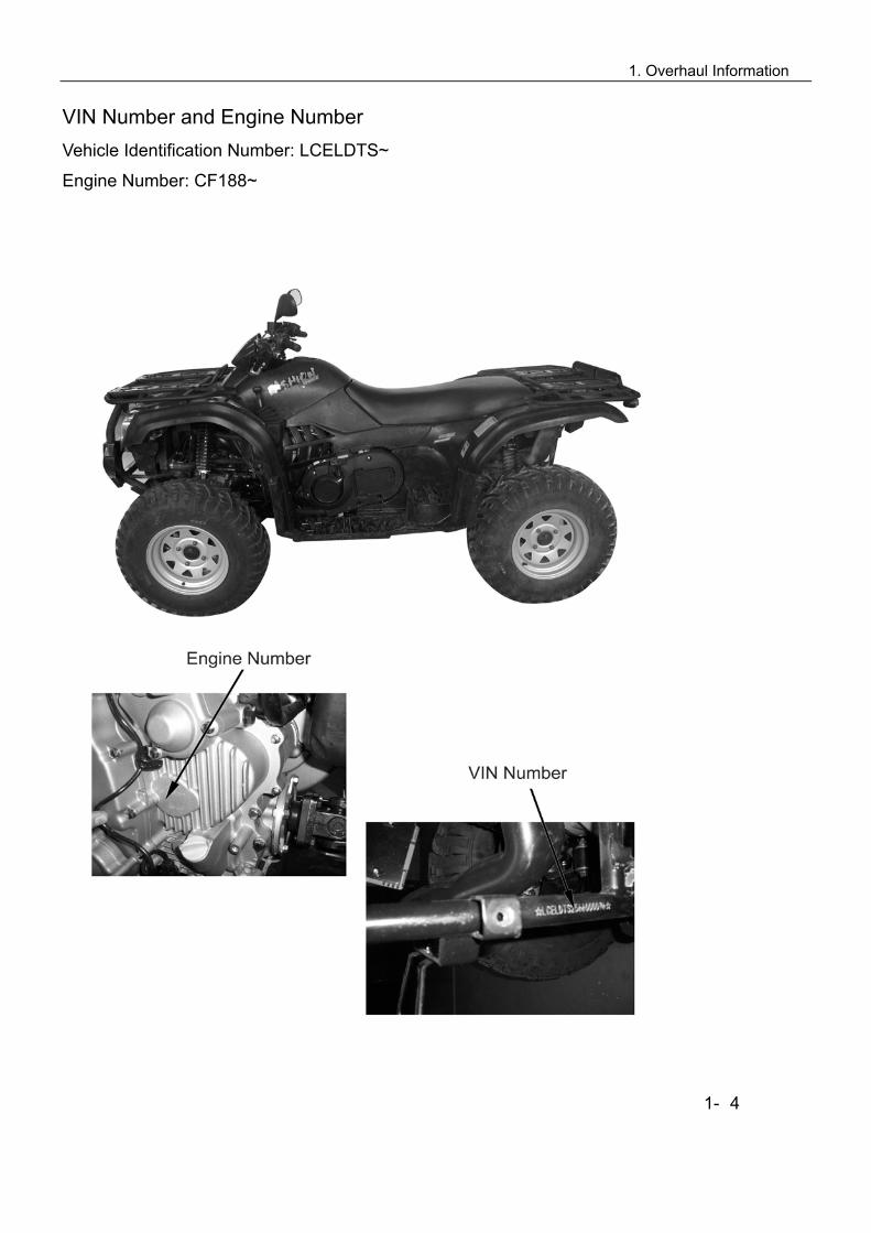
VIN Number and Engine Number Vehicle Identification Number: LCELDTS~
Engine Number: CF188~
1- 4

1. Overhaul Information
Main Data Table Item Parameter
Model CF500/CF500-A Length 2120mm/2320mm Width 1170mm Height 1230mm Wheel base 1290mm/1490mm Engine type CF188 Displacement 493ml Fuel type Unleaded gasoline 90 Octane or
above Dry weight 337Kg/340Kg Number of Passengers 1 for CF500, 2 for CF500-A
(including driver) Max. Load 150kg/225Kg
Front 25x8-12 Tire Rear 25x10-12 Ground Clearance 275mm Min. turning diameter 4.5m/4.8m
Starting Electrical starting/Recoil starting Engine type Single cylinder, 4-stroke,
Liquid-cooled, 4 valves, OHC Combustion chamber type Triangle Valve Driving type SOHC chain driving Bore x stroke 87.5mm X 82.0mm Compression Ratio 10.2:1 Max. power 24Kw/7000 rpm Max. torque 36N.M/5500 rpm Lubrication type Pressure & Splash Oil pump type Rotor Oil filter type Full flow filter screen
Engine
Cooling type Closed coolant circulation
1-5
1. Overhaul Information
1- 6
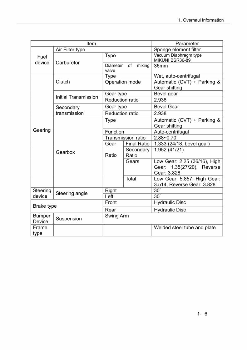
Item Parameter Air Filter type Sponge element filter
Type Vacuum Diaphragm type MIKUNI BSR36-89
Fuel device Carburetor Diameter of mixing
valve 36mm
Type Wet, auto-centrifugal Clutch Operation mode Automatic (CVT) + Parking &
Gear shifting Gear type Bevel gear
Initial Transmission Reduction ratio 2.938 Gear type Bevel Gear Secondary
transmission Reduction ratio 2.938 Type Automatic (CVT) + Parking &
Gear shifting Function Auto-centrifugal Transmission ratio 2.88~0.70
Final Ratio 1.333 (24/18, bevel gear) Secondary Ratio
1.952 (41/21)
Gears Low Gear: 2.25 (36/16), High Gear: 1.35(27/20), Reverse Gear: 3.828
Gearing
Gearbox
Gear Ratio
Total Low Gear: 5.857, High Gear: 3.514, Reverse Gear: 3.828
Right 30 Steering device Steering angle Left 30
Front Hydraulic Disc Brake type
Rear Hydraulic Disc Bumper Device Suspension Swing Arm
Frame type
Welded steel tube and plate

1. Overhaul Information
Overhaul Datasheet
Lubricating device Item Standard Service
limit Volume when replacing 1900ml — Engine Oil
Capacity
Full capacity 12200 ml —
Recommended Oil (see original)
Specially for 4-stroke motorcycle
SAE-10W-40、20W-50 Substitutes must be used in the following range. API type: SE or SF grade SAE type: Choose from the left chart according to the environmental temperature
Gap between inner and outer rotors
0.07~0.15mm 0.20mm
Gap between outer rotor and body
0.07~0.17mm 0.25mm Oil pump Rotor
End face gap 0.05~0.10mm 0.12mm Fuel Device
Item Standard Fuel Tank Capacity Full capacity 19.0l
Type MIKUNI BSR36-89 Main jet N102221-130# Idle jet N224103-22.5#
Carburetor
Idle speed 1300±100r/min Cooling Device
Item Standard
Full Capacity 1140ml Reservoir tank capacity 340ml
Coolant capacity Standard density 30% Opening pressure of radiator cap 108kpa(1.1kgf/cm2)
Temperature / valve open 72±2C Temperature/valve full open 88 C
Thermostat
Overall lift 3.5-4.5mm 1-7

1. Overhaul Information
Front Wheel Item Standard Service Limit
Vertical 1.0mm 2.0mm Play of wheel rim Horizontal 1.0mm 2.0mm Groove -- 3.0mm
Front Wheel Tire Pressure 35kpa(0.35kgf/cm3) --
Rear Wheel Item Standard Service Limit
Vertical 1.0mm 2.0mm Play of wheel rim Horizontal 1.0mm 2.0mm Groove -- 3.0mm
Rear wheel Tire Pressure 35kpa(0.35kgf/cm3) --
Brake System
Item Standard Service Limit Brake lever play 0mm -- Front brake Brake disc thickness 3.5mm 4mm Brake lever play 5-10mm -- Brake Pedal Play 0mm Rear brake
Brake disc thickness 7.5mm 6.5mm
Battery、Charging System Item Standard
Model Permanent magnet AC type Output 3- phase AC AC magneto Motor
Charging coil Resistance (20) 0.2-0.3Ω Rectifier
Three-phase annular rectification, Silicon controlled
parallel-connected regulated voltage Capacity 12V18Ah Fully charged 12.8V Terminal
point voltage
Insufficient charge <11.8V
Standard 0.9A/5~10H
Battery
Charging current/time Quick 4A/1H
Ignition system
Item Standard Ignition CDI ignition
Type DPR7EA-9(NGK) Optional DR8EA, D7RTC Spark Plug
Spark plug gap 0.8-0.9mm Ignition timing Max. advanced angle 32°CA
Ignition coil Above 200V Peak voltage Pulse generator 150V
1-8
1. Overhaul Information
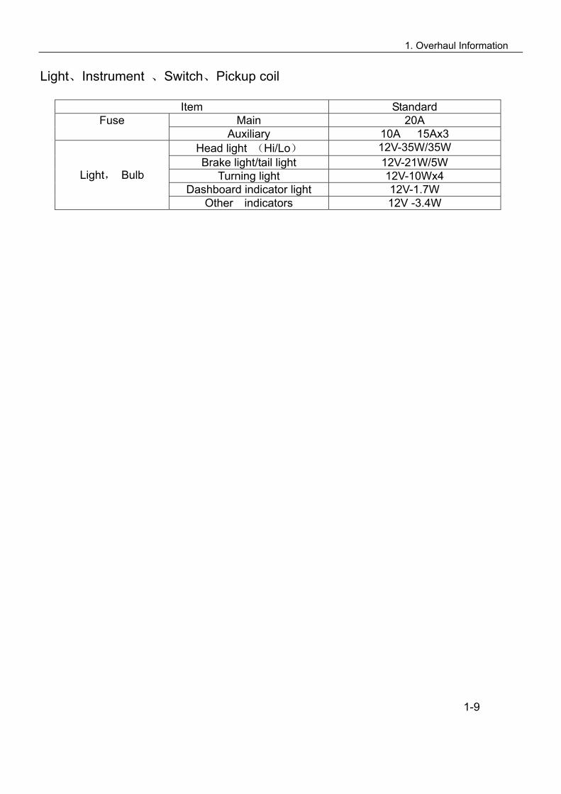
Light、Instrument 、Switch、Pickup coil
Item Standard Main 20A Fuse
Auxiliary 10A 15Ax3 Head light (Hi/Lo) 12V-35W/35W Brake light/tail light 12V-21W/5W
Turning light 12V-10Wx4 Dashboard indicator light 12V-1.7W
Light, Bulb
Other indicators 12V -3.4W
1-9

1. Overhaul Information
Tightening torque Item Torque N·m(kgf·m) Item Torque N·m(kgf·m)
5mm Bolt, nut 5(0.5) 5mm Screw 4(0.4)
6mm Bolt, nut 10(1.0) 6mm Screw 9(0.9) 8mm Bolt, nut 22(2.2) 6mmSH Bolt with flange, 10(1.0)
10mm Bolt, nut 34(3.5) 6mm Bolt with flange, nut 12(1.2) 12mm Bolt, nut 54(5.5) 8mm Bolt with flange, nut 26(2.7)
10mm Bolt with flange, nut 39(4.0) For others not listed in the chart, refer to the standard tightening torque. Notes: 1.Apply some engine oil on the part of screw thread and contact surface.
Item Thread Dia.
(mm)
Quantity Torque
N·m(kgf·m)
Front Upper Bolt, Engine M8x60 1 35~45
Rear Upper Bolt, Engine M10x1.25x110 1 40~50
Front Upper Bolt, Engine Bracket M8x14 1 35~45
Rear Upper Bolt, Engine Bracket M8x14 1 35~45
Lower Mounting Bold, Engine M12x1.25x140 2 50~60
Bolt, Swing Arm M10x1.25x70 16 40~50
Bolt, Rear Absorber M10x1.25x50 4 40~50
Bolt, Front Absorber M10x1.25x50 4 40~50
Bolt, Rear Wheel Support M10x1.25x100 4 40~50
Mounting Nut, Rim 901-07.00.02 M20 16 50~60
Nut, Rim Shaft 901-07.00.03 M10 4 110~130
Mounting Screw, Rear Brake Pump M6x25 2 18~22
Bolt, Rear Brake Caliper M10x1.25x20 2 40~50
Bolt, Front Brake Disc 901-08.00.03 M8 8 25~30
Bolt, Front Brake Caliper M8x14 4 35~45
Bolt, Handlebar M8x55 4 20~30
Nut, Tie-rod M10x1.25 4 40~50
Locknut, Steering Stem M14x1.5 1 100~120
Rear Mounting Bolt, Muffler M8x30 1 30~50
Bolt, Exhaust Pipe M8x14 1 30~35
Mounting Bolt, Muffler M8x40 1 30~35
Mounting Bolt, Rear Axle M10x1.25x110 2 40~50
Mounting Bolt, Front Axle M10x1.25x90 1 40~50
Mounting Bolt, Front Axle M10x1.25x25 2 40~50
Bolt, Front Axle Support M8x14 2 35~45
Bolt, Rear Transmission Shaft Rear End 901-30.00.01 6 40~50
Bolt, Rear Transmission Shaft Front End 901-29.00.01 4 35~45
Bolt, Front Transmission Shaft 901-29.00.01 8 35~45
Thermoswitch CF250T-420500 1 28~30
Bolt 1, Front Rack M8x14 2 35~45
Bolt 2, Front Rack M6x12 2 25~30
Bolt, Rear Rack M8x14 4 35x45
1- 10

1. Overhaul Information
Lubricant, Sealing Agent Application Areas Cautions Lubricants & Grease
Oil Seal Lip, Steering Stem
Pivot, Rear Brake Pedal
Joints, Throttle Cable
Throttle Lever
Multi-purpose Lubricating
Grease
Dust-proof Seal Lip, Front
Shock absorber
#5 Absorber Oil
Inner surface, Handlebar Engine Oil
1-11

1. Overhaul Information
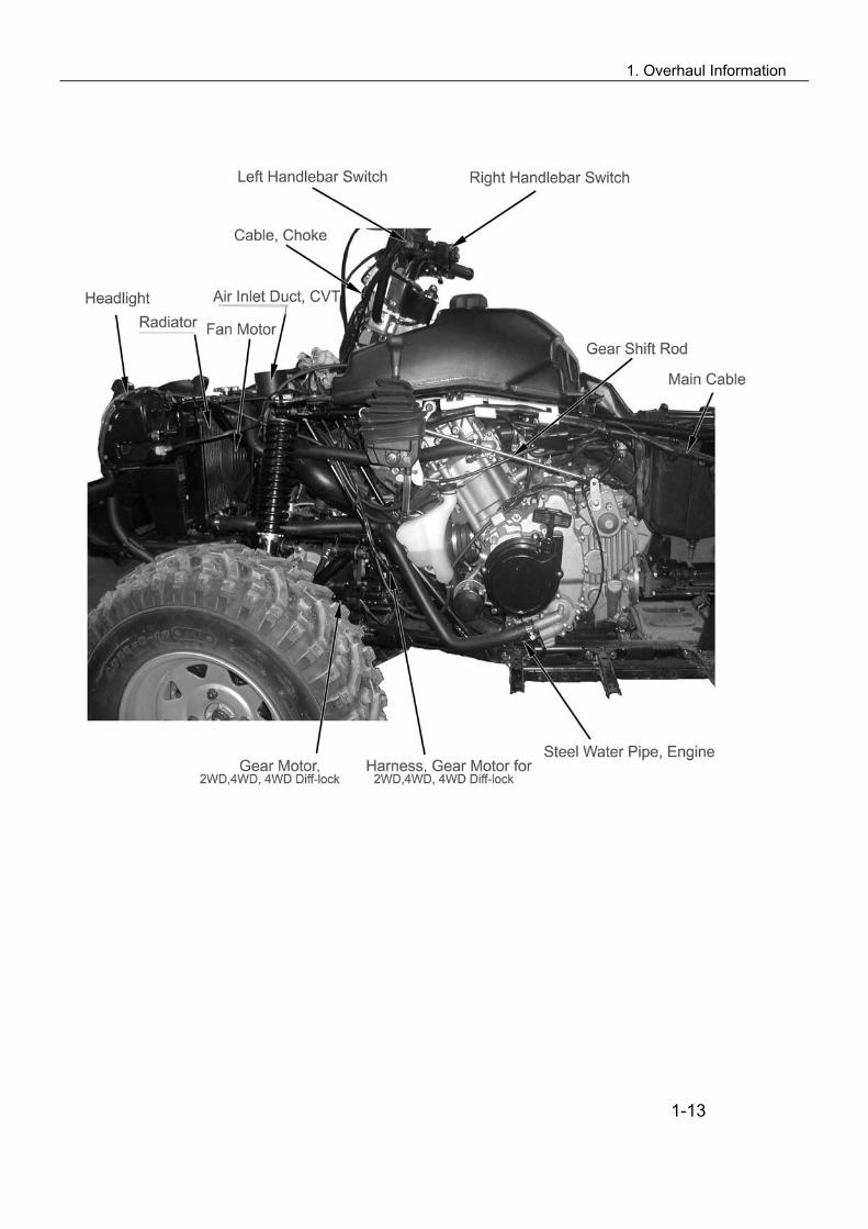
Cable Routing
1. Connector, Fan Motor 2. Connector, CDI 1. Ignition Coil 2. Water Temperature Sensor 3. CDI 4. Wire Clip 3. Cable, Parking 4. Breather Hose, Reservoir Tank 5. Connector, Starting Switch 5. Vacuum Tube 6. Wire Clip 6. Connector, Dashboard 7. Connector for Magneto, Gear Sensor and Pickup Coil 7. Connector, Handlebar Switch (L&H) 8. Fuel Pipe, Carburetor 8. Connector, Ignition Switch 9. Wire, Starting Motor 9. Wire Clip 10. Steel Wire Clip 1-12
1. Overhaul Information
1-13

1. Overhaul Information
1-14

1. Overhaul Information
1-15

2. Vehicle Body, Muffler
Overhaul Info…………………… ….………….2-1 Troubleshooting……….….……….……………..2-1 Front Rack, Bolt Cap………………………….…2-2 Seat, Seat Support & Rear Rack……………….2-3 Front & Rear Rack Panels, Front Top Cover….2-4 Rear Top Cover……………………..…………....2-5 Left Side Panel…………………………………...2-6 Right Side Panel……………………………….…2-7 Fuel Tank Top Cover, Front Fender…………....2-8 Footrest Board (LH, RH)………………………...2-9
Rear Fender, Engine Skid Plate (Front, Center, Rear), Double Seat, Protection Plate……………………………..2-10 Front Inner Fender (RH,LH), Front Protector (RH, LH)…2-12 Rear Protector (RH,LH), Bumper, Bumper Protector……2-13 Bumper Cap…………………………………..……………..2-14 Front Vent Grille, Fuel Tank…………………….………….2-15 Bottom Plate, Fuel Tank…………………………………….2-16 Muffler……………………………………….………………..2-17 Description of Visible Parts………….…………………..…2-18
Overhaul Information Operation Cautions Warning Gasoline is highly flammable, therefore smoke and fire are strictly forbidden in the work place. Special attention should also be paid to sparks. Gasoline may also be explosive when it is vaporized, so operation should be done in a well-ventilated place. Remove and Install muffler after it is fully cold.
This chapter is on the disassembly and installation of rack, visible parts, exhaust pipe, muffler and fuel
tank. Hoses, cables and wiring should be routed properly. Replace the gasket with a new one after muffler is removed. After muffler is installed, check if there is any exhaust leakage.
Tightening torque Muffler Rear Fixing Bolt: 35-45N.m Muffler Exhaust Pipe Bolt: 35-45N.m Muffler Body Fixing Bolt: 35-45N.m
Troubleshooting Loud exhaust noise
Broken muffler Exhaust leakage
Insufficient power
Distorted muffler Exhaust leakage Muffler clogged
2-1
2. Vehicle Body, Muffler
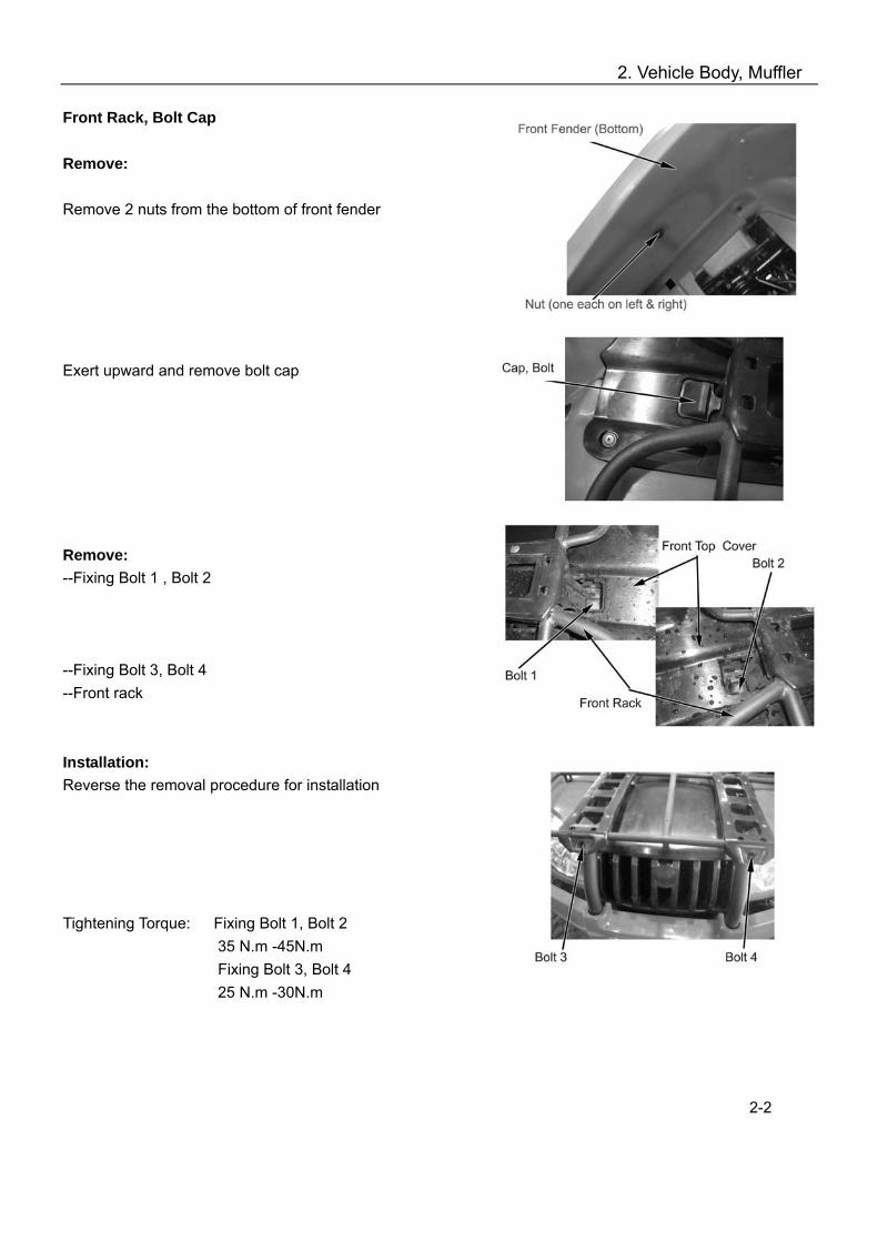
Front Rack, Bolt Cap Remove: Remove 2 nuts from the bottom of front fender Exert upward and remove bolt cap Remove: --Fixing Bolt 1 , Bolt 2 --Fixing Bolt 3, Bolt 4 --Front rack Installation: Reverse the removal procedure for installation Tightening Torque: Fixing Bolt 1, Bolt 2 35 N.m -45N.m Fixing Bolt 3, Bolt 4
25 N.m -30N.m
2-2
2. Vehicle Body, Muffler
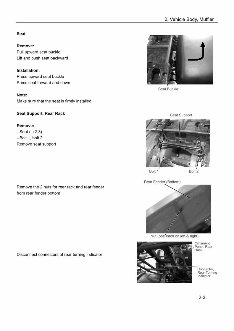
Seat Remove: Pull upward seat buckle Lift and push seat backward Installation: Press upward seat buckle Press seat forward and down Note: Make sure that the seat is firmly installed. Seat Support, Rear Rack Remove: --Seat (→2-3) --Bolt 1, bolt 2 Remove seat support Remove the 2 nuts for rear rack and rear fender from rear fender bottom Disconnect connectors of rear turning indicator
2-3

2. Vehicle Body, Muffler
Remove Bolt 1, Bolt 2 Remove rear rack Installation Reverse the removal procedure for installation
Tightening Torque: Fixing Bolt, Rear Rack 35 N.m -45N.m Ornament Panel, Front Rack Remove: Remove four tapping screw from front rack Installation: Reverse the removal procedure for installation. Ornament Panel, Rear Rack Repeat above procedure for removal and installation of ornament panel, rear rack. Front Top Cover Remove: Remove front rack (→2-2) Push upward plastic screw from front fender bottom with a flat screwdriver; Remove plastic screw and plastic screw seat Separate clasps of top cover from fuel tank and front fender as illustrated on the right; Push forward and remove front top cover.
2-4

2. Vehicle Body, Muffler
Installation: Reverse the removal procedure of installation. Rear Top Cover Remove: --Rear rack (→2-3) Separate clasps of rear top cover from rear fender Remove rear top cover Installation: Reverse the removal procedure and direction for installation.
2-5
2. Vehicle Body, Muffler
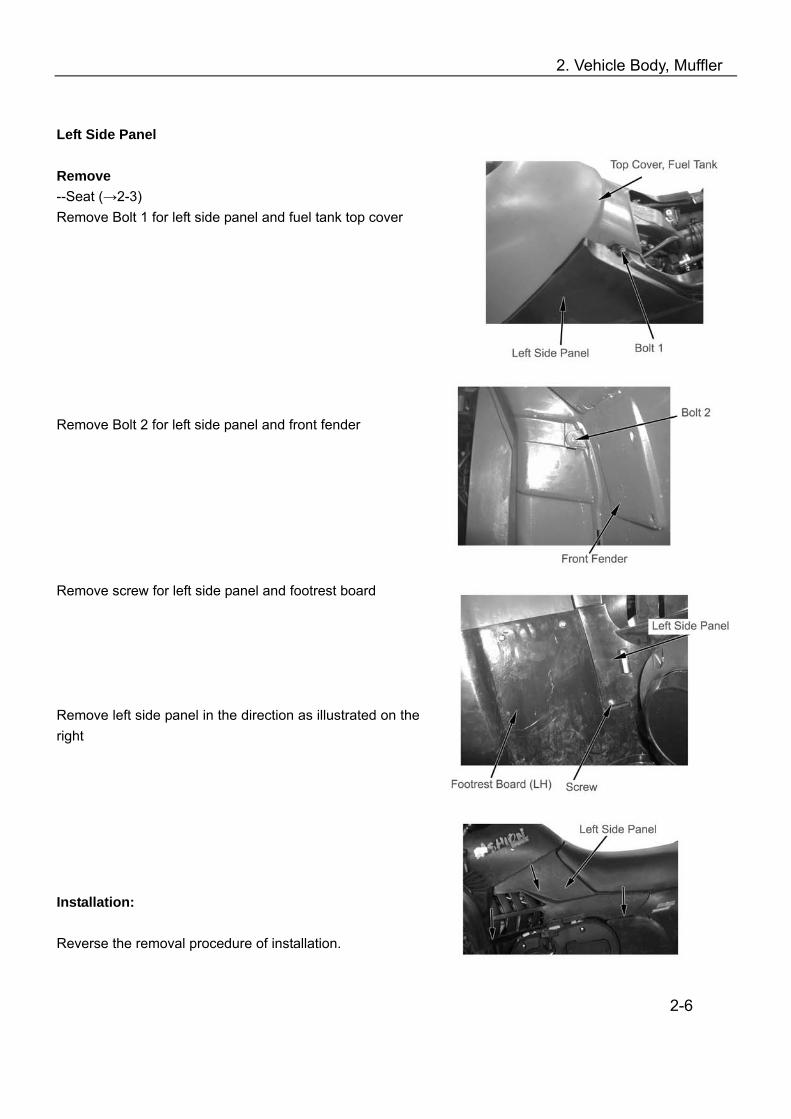
Left Side Panel Remove --Seat (→2-3) Remove Bolt 1 for left side panel and fuel tank top cover Remove Bolt 2 for left side panel and front fender
Remove screw for left side panel and footrest board Remove left side panel in the direction as illustrated on the right Installation: Reverse the removal procedure of installation.
2-6
2. Vehicle Body, Muffler
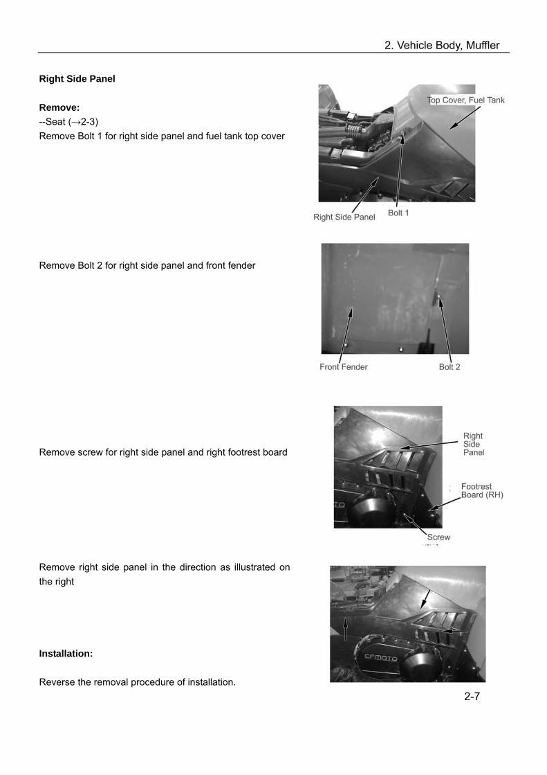
Right Side Panel Remove: --Seat (→2-3) Remove Bolt 1 for right side panel and fuel tank top cover
Remove Bolt 2 for right side panel and front fender Remove screw for right side panel and right footrest board Remove right side panel in the direction as illustrated on the right Installation: Reverse the removal procedure of installation.
2-7

2. Vehicle Body, Muffler
Top Cover, Fuel Tank Remove: --Seat (→2-3) --Front rack (→2-2) --Front top cover (→2-4) --Left side panel (→2-6) --Right side panel (→2-7) --Bolt 1, Bolt 2 --Bolt 3, Bolt 4 --Top cover, fuel tank Installation: Reverse the removal procedure of installation. Front Fender Remove: --Front rack (→2-2) --Front top cover (→2-4) --Left side panel (→2-6) --Right side panel (→2-7) --Top cover, fuel tank (→2-8) Disconnect wiring connectors from front fender; Remove electrical components from front fender; Remove 3 bolts from frame Remove 6 screws and nuts from left and right footrest board Remove front fender
2-8
2. Vehicle Body, Muffler
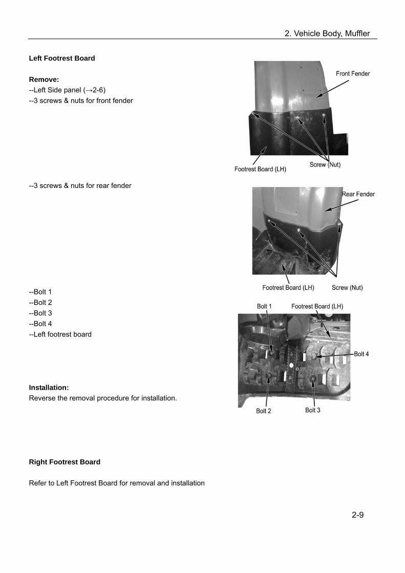
Left Footrest Board Remove: --Left Side panel (→2-6) --3 screws & nuts for front fender
--3 screws & nuts for rear fender --Bolt 1 --Bolt 2 --Bolt 3 --Bolt 4 --Left footrest board Installation: Reverse the removal procedure for installation. Right Footrest Board Refer to Left Footrest Board for removal and installation
2-9

2. Vehicle Body, Muffler
Rear Fender Remove: --Seat (→2-3) --Rear rack(→2-3) --Rear top cover (→2-5) --Left & right side panel (→2-6) (→2-7) --Battery fixing plate, battery cover (→8-4) Remove battery Remove electrical components from rear fender (Chapter 8) Disconnect wiring connectors from rear fender (Chapter 8) Lift upward and remove rear fender Engine Skid Plate(Front), Engine Skid Plate (Center), Double Seat Protection Plate, & Engine Skid Plate ( Rear)
(1) Bolt 1
(2) Bolt 2
(3) Engine Skid Plate( Front)
(4) Bolt 3
(5) Bolt 4
(6) Engine Skid Plate (Center)
(7) Bolt 5
(8) Bolt 6
(9) Bolt 7
(10) Bolt8
(11) Double Seat Protection Plate
(12) Engine Skid Plate (Rear)
(13, 14) Bolt 9
(15) Bolt 10
2-10

2. Vehicle Body, Muffler
Disassembly Note: Side skid plate (front), side skid plate (center), side skid plate (rear) and double seat protection plate are located at the bottom of vehicle. The maintenance person should have to work under the vehicle bottom when disassembling the above parts. For safety purpose, make sure that the vehicle should be firmly parked. Engine Skid Plate (Front) Remove: --Bolt 1 --Bolt 2 --Bolt 3 --Bolt 4 --Engine skid plate (Front) Installation: Reverse the removal procedure for installation. Engine Skid Plate (Center) Remove: --Bolt 5 --Bolt 6 Engine skid plate (center) Installation: Reverse the removal procedure of installation. Double Seat Protection Plate Remove: --Bolt 7 --Bolt 8 --Double seat protection plate Note: This part is not available for single seat vehicle. Installation: Reverse the removal procedure of installation. Engine Skid Plate (Rear) Remove: --Bolt 9 --Bolt 10 Engine skid plate (rear) Installation: Reverse the removal procedure for installation.
2-11

2. Vehicle Body, Muffler
Front Right Inner Fender Remove: --Bolt 1 --Bolt 2 --Front right inner fender Installation: Reverse the removal procedure for installation. Note: The clasp of front right inner fender should hook water pipe when it is assembled. Front Left Inner Fender Remove: --Bolt 1 --Bolt 2 --Front left inner fender Installation: Reverse the removal procedure for installation. Front Left Protector Remove: Bolt 1 Pull backward and remove front left protector Installation: Reverse the removal procedure for installation. Front Right Protector Repeat the above procedure of removal and installation for front right protector.
2-12
2. Vehicle Body, Muffler
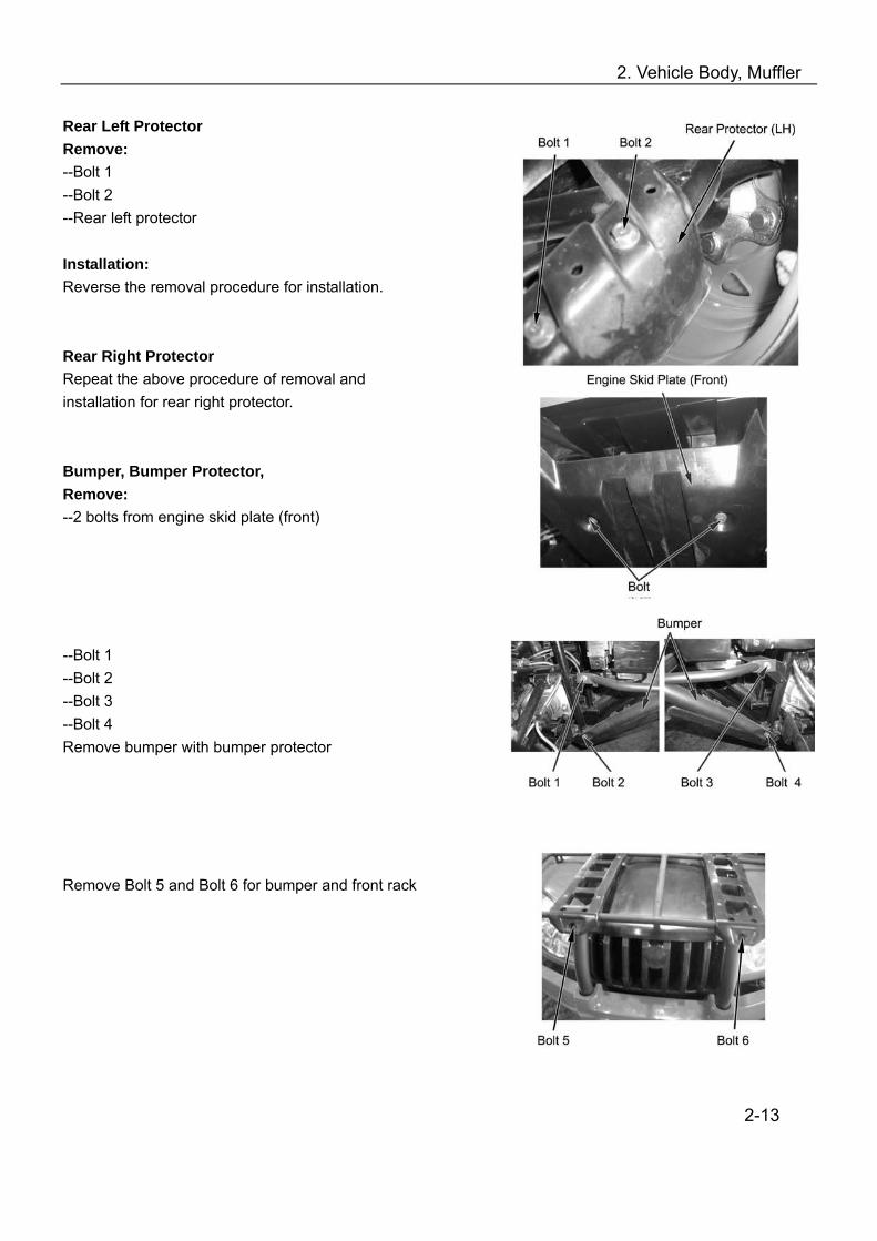
Rear Left Protector Remove: --Bolt 1 --Bolt 2 --Rear left protector Installation: Reverse the removal procedure for installation. Rear Right Protector Repeat the above procedure of removal and installation for rear right protector. Bumper, Bumper Protector, Remove: --2 bolts from engine skid plate (front) --Bolt 1 --Bolt 2 --Bolt 3 --Bolt 4 Remove bumper with bumper protector Remove Bolt 5 and Bolt 6 for bumper and front rack
2-13
2. Vehicle Body, Muffler
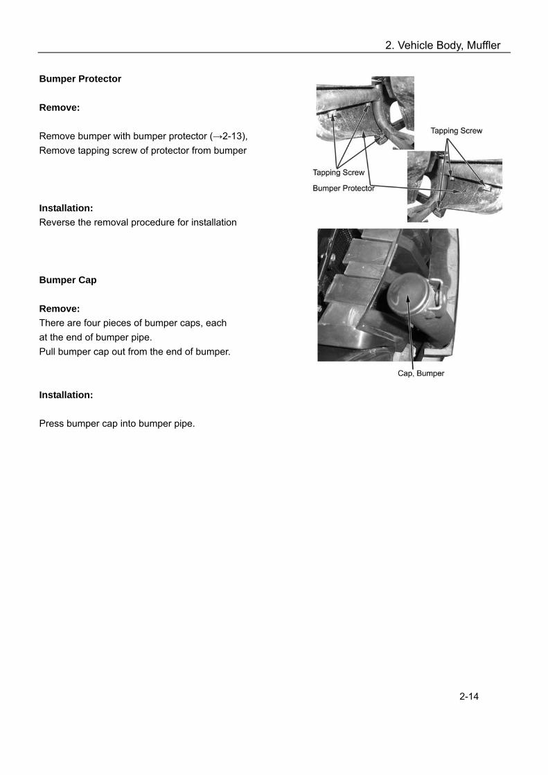
Bumper Protector Remove: Remove bumper with bumper protector (→2-13), Remove tapping screw of protector from bumper Installation: Reverse the removal procedure for installation Bumper Cap Remove: There are four pieces of bumper caps, each at the end of bumper pipe. Pull bumper cap out from the end of bumper. Installation: Press bumper cap into bumper pipe.
2-14
2. Vehicle Body, Muffler
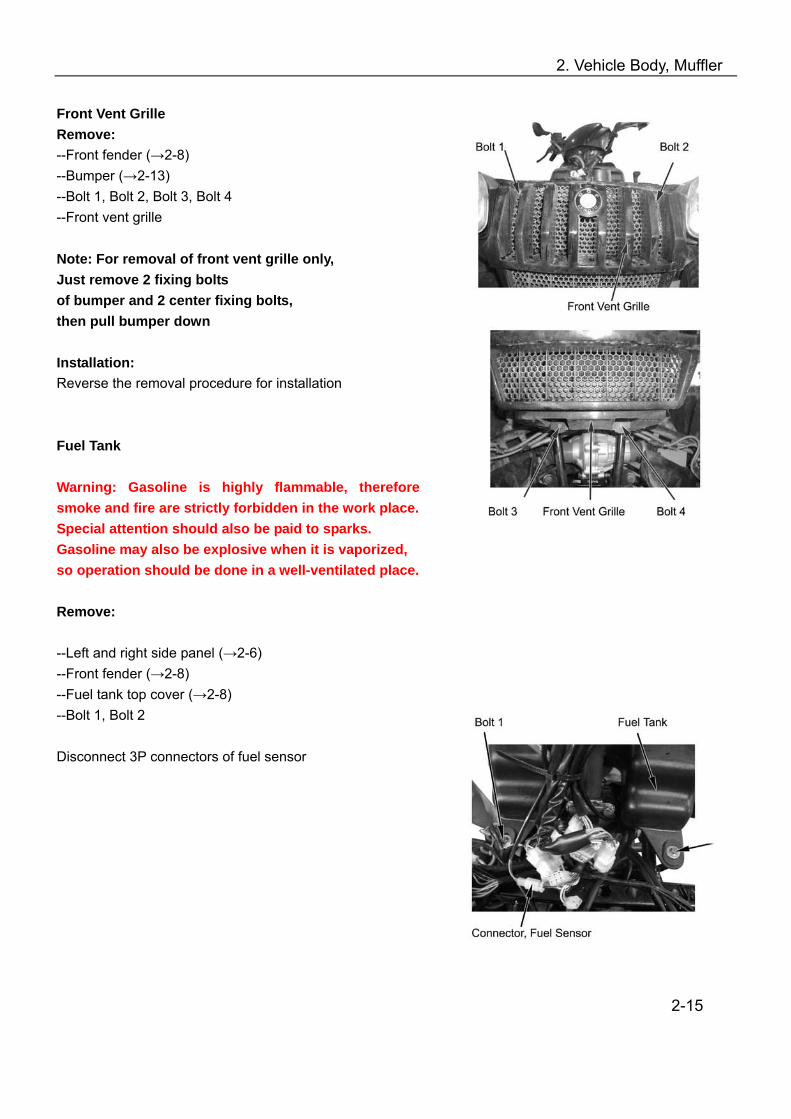
Front Vent Grille Remove: --Front fender (→2-8) --Bumper (→2-13) --Bolt 1, Bolt 2, Bolt 3, Bolt 4 --Front vent grille Note: For removal of front vent grille only, Just remove 2 fixing bolts of bumper and 2 center fixing bolts, then pull bumper down Installation: Reverse the removal procedure for installation Fuel Tank Warning: Gasoline is highly flammable, therefore smoke and fire are strictly forbidden in the work place. Special attention should also be paid to sparks. Gasoline may also be explosive when it is vaporized, so operation should be done in a well-ventilated place. Remove: --Left and right side panel (→2-6) --Front fender (→2-8) --Fuel tank top cover (→2-8) --Bolt 1, Bolt 2 Disconnect 3P connectors of fuel sensor
2-15
2. Vehicle Body, Muffler
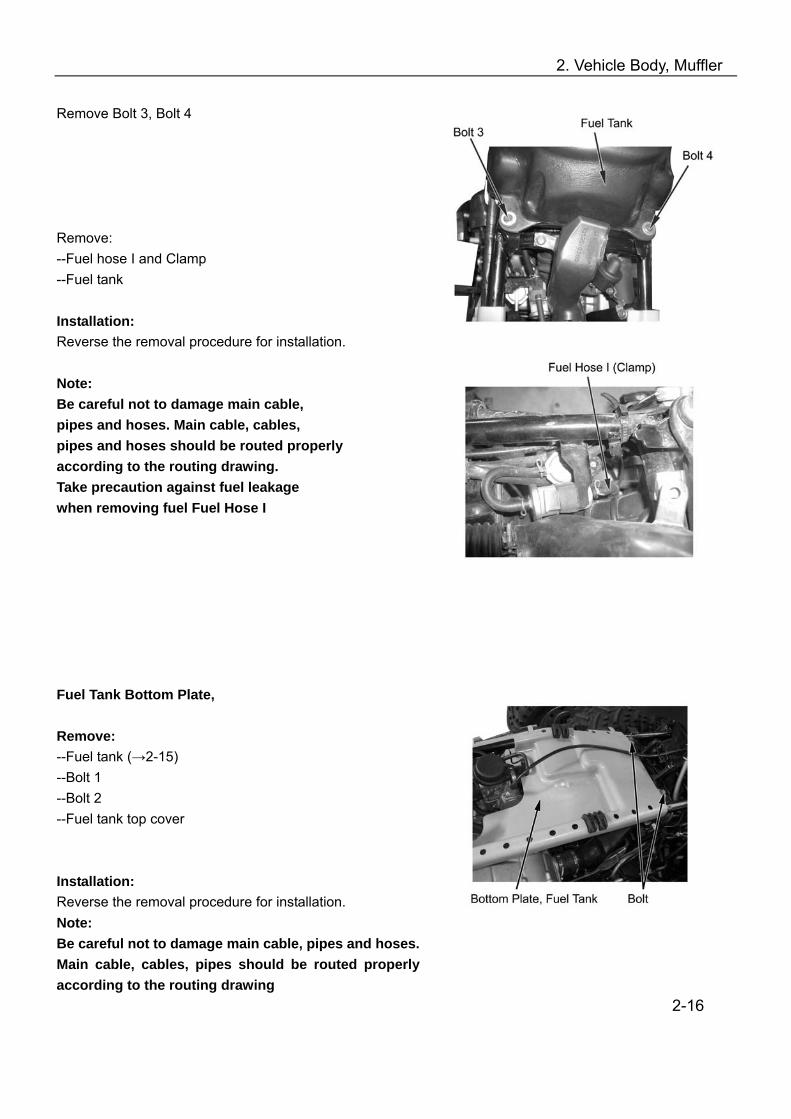
Remove Bolt 3, Bolt 4 Remove: --Fuel hose I and Clamp --Fuel tank Installation: Reverse the removal procedure for installation. Note: Be careful not to damage main cable, pipes and hoses. Main cable, cables, pipes and hoses should be routed properly according to the routing drawing. Take precaution against fuel leakage when removing fuel Fuel Hose I Fuel Tank Bottom Plate, Remove: --Fuel tank (→2-15) --Bolt 1 --Bolt 2 --Fuel tank top cover Installation: Reverse the removal procedure for installation. Note: Be careful not to damage main cable, pipes and hoses. Main cable, cables, pipes should be routed properly according to the routing drawing
2-16
2. Vehicle Body, Muffler
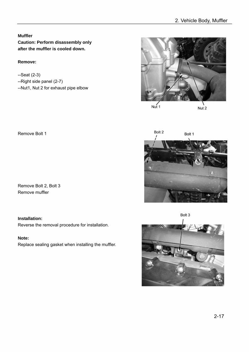
Muffler Caution: Perform disassembly only after the muffler is cooled down. Remove: --Seat (2-3) --Right side panel (2-7) --Nut1, Nut 2 for exhaust pipe elbow Remove Bolt 1 Remove Bolt 2, Bolt 3 Remove muffler Installation: Reverse the removal procedure for installation. Note: Replace sealing gasket when installing the muffler.
2-17
2. Vehicle Body, Muffler
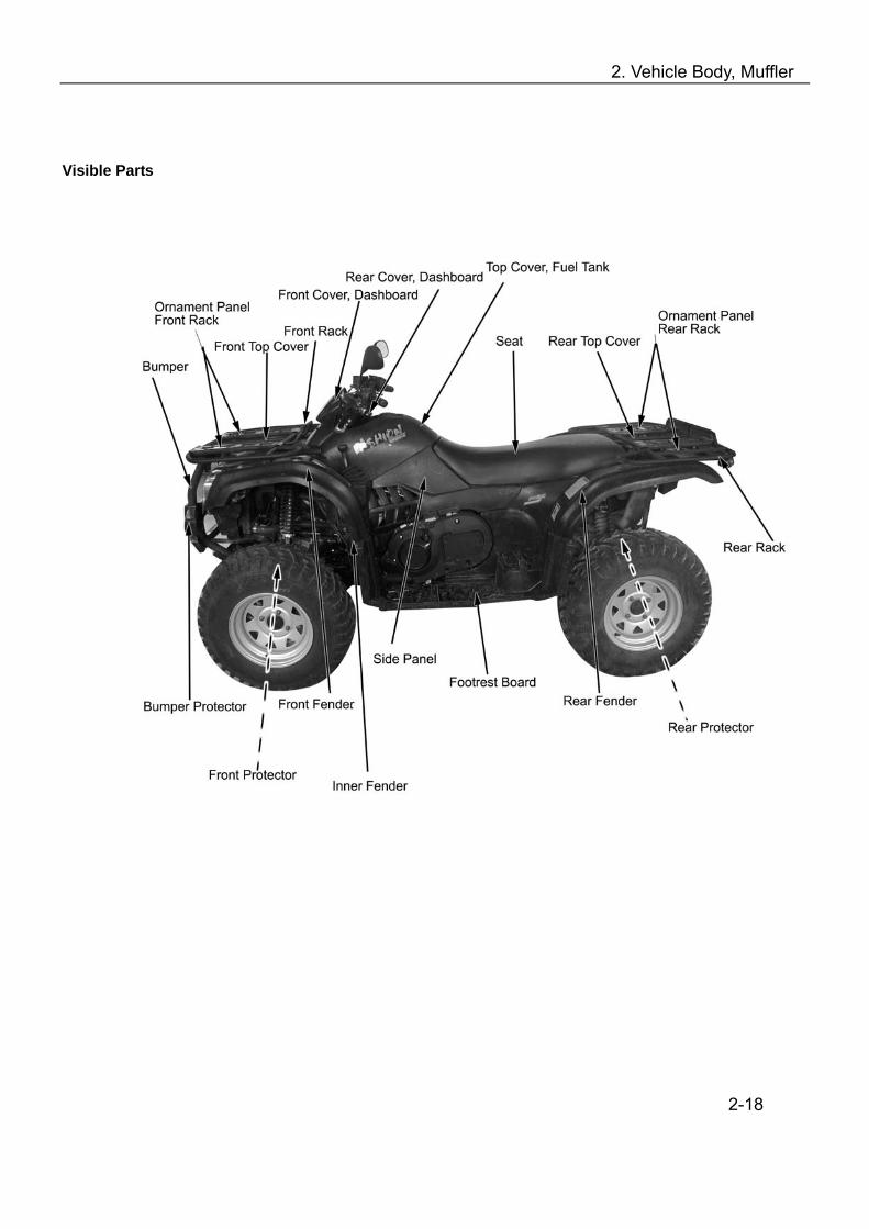
Visible Parts
2-18
3. Checks & Adjustment
Overhaul Info……………………………..3-1 Inspection & Maintenance………………3-2 Steering Stem, Brake System…………..3-5 Wheels…………………………………….3-7
Suspension System…………………..3-9 Gear Shifting, Fuel Device…………...3-10 Cooling System..………………………3-12 Lighting System...……………………...3-14
Overhaul info Operation Cautions Note
DO NOT keep the engine running for long time in a poorly ventilated or enclosed place because of the harmful components like CO, etc, in the exhaust gas.
The muffler and engine are still very hot when the engine is just stopped. Careless contact may cause serious burn. Be sure to wear fatigue dress with long sleeves and gloves if the work has to be done after the engine is just stopped.
Gasoline is highly flammable, smoking is strictly forbidden in the work place. Keep alert on the electrical sparks. Besides, vaporized gasoline is highly explosive, so work should be done in a well-ventilated place.
Be careful that your hands or clothes not get nipped by the turning or movable parts of the driving system.
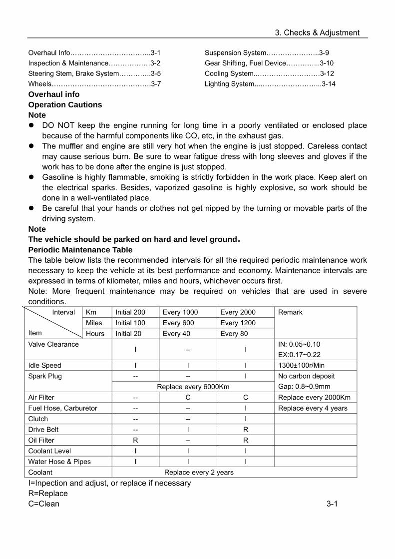
Note The vehicle should be parked on hard and level ground。 Periodic Maintenance Table The table below lists the recommended intervals for all the required periodic maintenance work necessary to keep the vehicle at its best performance and economy. Maintenance intervals are expressed in terms of kilometer, miles and hours, whichever occurs first. Note: More frequent maintenance may be required on vehicles that are used in severe conditions.
Km Initial 200 Every 1000 Every 2000 Miles Initial 100 Every 600 Every 1200
Interval
Item Hours Initial 20 Every 40 Every 80
Remark
Valve Clearance I -- I
IN: 0.05~0.10 EX:0.17~0.22
Idle Speed I I I 1300±100r/Min -- -- I Spark Plug
Replace every 6000Km No carbon deposit Gap: 0.8~0.9mm
Air Filter -- C C Replace every 2000Km Fuel Hose, Carburetor -- -- I Replace every 4 years Clutch -- -- I Drive Belt -- I R Oil Filter R -- R Coolant Level I I I Water Hose & Pipes I I I Coolant Replace every 2 years I=Inpection and adjust, or replace if necessary R=Replace C=Clean 3-1

3. Checks & Adjustment
Inspection & Maintenance : Interval Item Intervals
Part Item Daily 1/2 Year A n n u a l
Standard
Handlebar Operation agility
Damage Installation condition of
steering system
Steering System Steering system
Sway of ball stud
Free play Front: lever end 0mm
Rear : lever end 0mm Brake lever Brake
Efficiency
Connecting rod, oil pipe & Hose
Looseness, Slack and damage
Front and rear brake fluid
level
Brake fluid should be above LOWER limit
Brake System
Hydraulic brake and brake disc Brake disc
damage and wear
Replace when the thickness of front brake disc is less than 2.5mm, rear brake less than 6.5mm.
Tire pressure
Front tire: 35kPa (0.350kgf/ 2) Rear tire: 35kPa (0.35kgf/ 2)
Chap and damage
Groove depth and abnormal wear
No wear indication on the surface of tire (the remained depth of groove should not be less than 1.6mm)
Loosened wheel nut and axle
Sway of front wheel bearing
Driving
System Wheel
Sway of rear wheel bearing
3-2
3. Checks & Adjustment
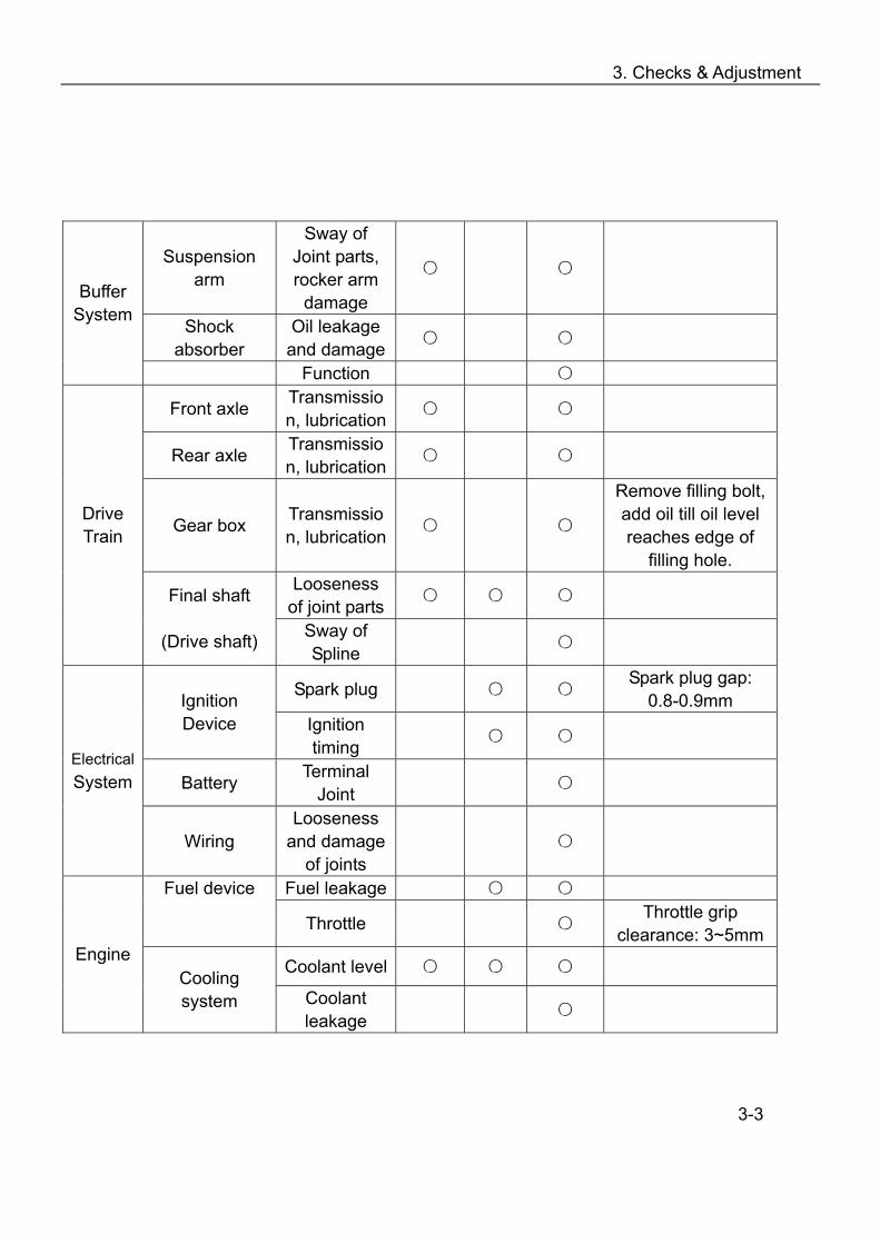
Suspension arm
Sway of Joint parts, rocker arm
damage
Shock absorber
Oil leakage and damage
Buffer System
Function
Front axle Transmission, lubrication
Rear axle Transmission, lubrication
Gear box Transmission, lubrication
Remove filling bolt, add oil till oil level reaches edge of
filling hole. Looseness
of joint parts
Drive Train
Final shaft
(Drive shaft) Sway of Spline
Spark plug Spark plug gap: 0.8-0.9mm Ignition
Device Ignition timing
Battery Terminal Joint
Electrical System
Wiring Looseness
and damage of joints
Fuel leakage Fuel device Throttle Throttle grip
clearance: 3~5mm
Coolant level Engine
Cooling system Coolant
leakage
3-3
3. Checks & Adjustment
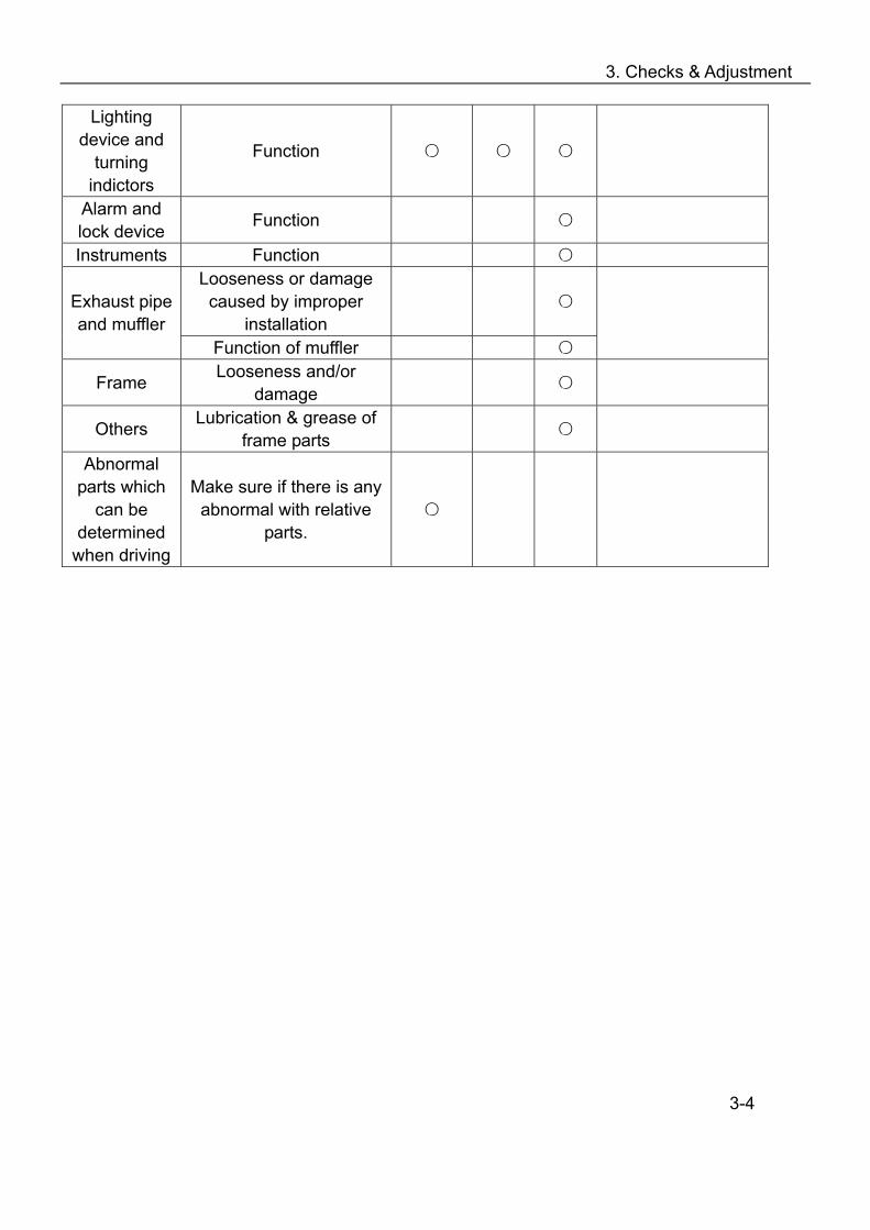
Lighting device and
turning indictors
Function
Alarm and lock device Function
Instruments Function Looseness or damage caused by improper
installation
Exhaust pipe
and muffler Function of muffler
Frame Looseness and/or damage
Others Lubrication & grease of frame parts
Abnormal parts which
can be determined
when driving
Make sure if there is any abnormal with relative
parts.
3-4
3. Checks & Adjustment
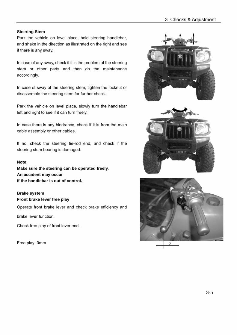
Steering Stem Park the vehicle on level place, hold steering handlebar, and shake in the direction as illustrated on the right and see if there is any sway. In case of any sway, check if it is the problem of the steering stem or other parts and then do the maintenance accordingly. In case of sway of the steering stem, tighten the locknut or disassemble the steering stem for further check. Park the vehicle on level place, slowly turn the handlebar left and right to see if it can turn freely. In case there is any hindrance, check if it is from the main cable assembly or other cables. If no, check the steering tie-rod end, and check if the steering stem bearing is damaged. Note: Make sure the steering can be operated freely. An accident may occur if the handlebar is out of control. Brake system Front brake lever free play
Operate front brake lever and check brake efficiency and
brake lever function.
Check free play of front lever end.
Free play: 0mm
3-5

3. Checks & Adjustment
Master Cylinder <Fluid level> Check the brake fluid level When the brake fluid level is near to the lower limit line, check master cylinder, brake hoses and joints for leakage. Remove the two mounting screws on fluid reservoir cap. Remove the cap, add DOT3 or DOT4 brake liquid till the upper limit line. ·Do not mix with dust or water when adding brake fluid. ·Use only the recommended of brake fluid
to avoid chemical reaction. ·Brake fluid may cause damages to the surface of the
plastic and rubber parts. Keep the fluid away from these parts.
·Slightly turn the handlebar left and right till the master cylinder is in horizontal, then remove the fluid reservoir cap.
Brake Disc, Brake Pad < Wear of brake pad> Check the brake pad wears from the mark as indicated. Replace the brake pad if the wear has reached position of wear limit trough. Note The brake pad must be replaced with a whole set. Checking and replacing the brake disc Front brake disc thickness: ≤2.5 mm →Replace Rear brake disc: ≤6.5 mm →Replace Min. limited thickness of the front brake disc: 2.5mm Min. limited thickness of the rear brake disc: 6.5mm Change the Brake Fluid < Changing Brake Fluid>
Change the brake fluid once every year.
3-6

3. Checks & Adjustment
Wheels Lift front wheel on level place, and make sure there is no loading on the wheels. Shake the front wheel left and right to check whether the joint of front wheel is tightened and check whether it sways. Not tighten enough: →Tighten it Sway: →Replace the rocker arm Front Toe-in size Park the vehicle on level place, measure the front toe-in Toe-in: B-A=0-10mm Toe-in out of the range: → Adjust the locknut of tie-rod Note: After the toe-in has been adjusted, slowly run the vehicle to check whether the direction of vehicle can be controlled by handlebar.
3-7

3. Checks & Adjustment
Tire Pressure
Check the pressure of the tires with a pressure gauge.
Note
Check the tire pressure after tires are cooled.
Driving under improper tire pressure will reduce the comfort
of operation and riding, and may cause deflected wear of the
tires.
Specified pressure /tire
Front wheel Rear wheel
Press
ure
35kPa(.035k
gf/cm2)
35kPa(0.50k
gf/cm2)
Tire
Size
25×8-12 25×10-12
Tire Tread
Check the tire tread. Tread Height: < 3mm→Replace with new tires Note: When the tread height is less than 3mm, the tire should be replaced immediately.
3-8
3. Checks & Adjustment
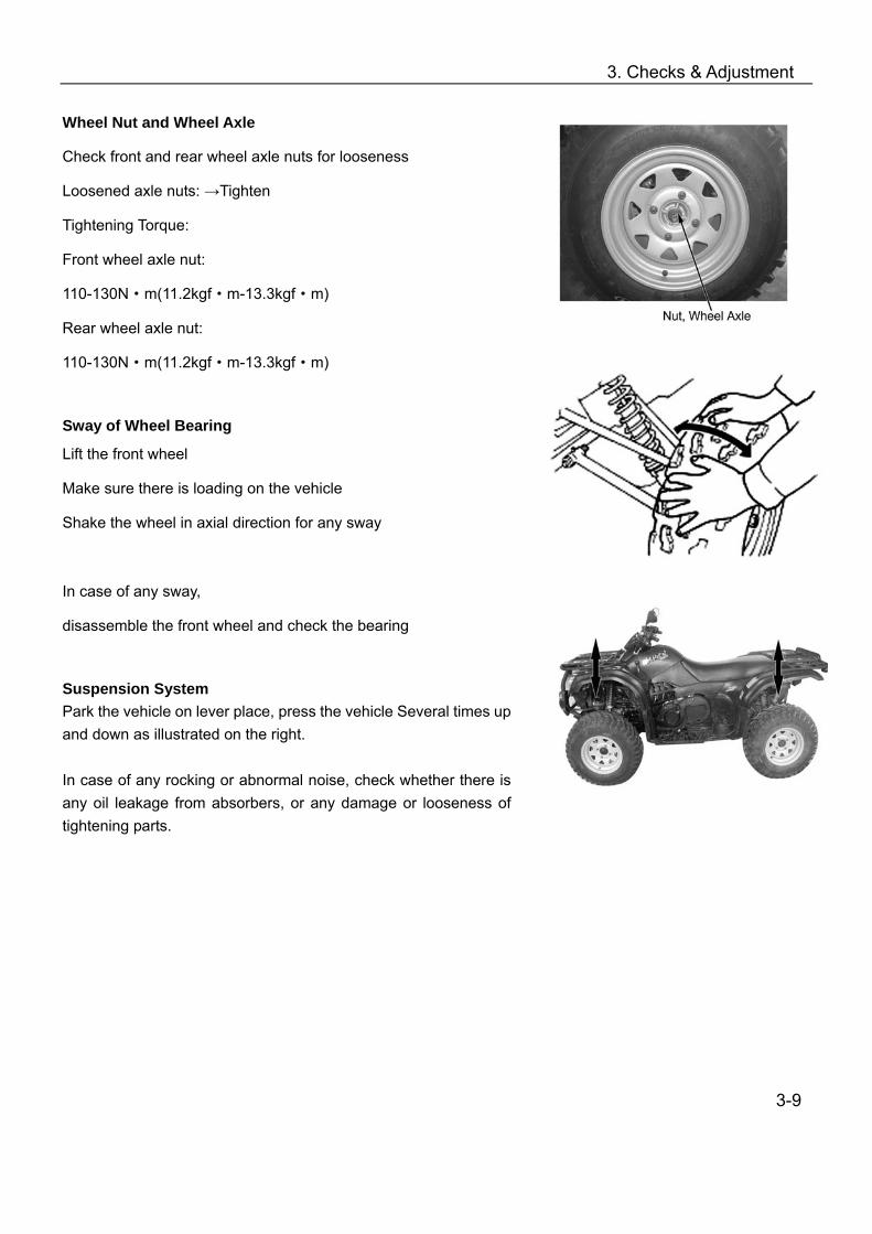
Wheel Nut and Wheel Axle
Check front and rear wheel axle nuts for looseness
Loosened axle nuts: →Tighten
Tightening Torque:
Front wheel axle nut:
110-130N·m(11.2kgf·m-13.3kgf·m)
Rear wheel axle nut:
110-130N·m(11.2kgf·m-13.3kgf·m)
Sway of Wheel Bearing
Lift the front wheel
Make sure there is loading on the vehicle
Shake the wheel in axial direction for any sway
In case of any sway,
disassemble the front wheel and check the bearing
Suspension System Park the vehicle on lever place, press the vehicle Several times up and down as illustrated on the right. In case of any rocking or abnormal noise, check whether there is any oil leakage from absorbers, or any damage or looseness of tightening parts.
3-9
3. Checks & Adjustment
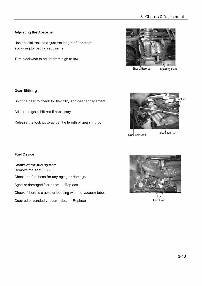
Adjusting the Absorber Use special tools to adjust the length of absorber according to loading requirement Turn clockwise to adjust from high to low Gear Shifting Shift the gear to check for flexibility and gear engagement Adjust the gearshift rod if necessary Release the locknut to adjust the length of gearshift rod Fuel Device Status of the fuel system Remove the seat (→2-3)
Check the fuel hose for any aging or damage.
Aged or damaged fuel hose: → Replace
Check if there is cracks or bending with the vacuum tube.
Cracked or bended vacuum tube: → Replace
3-10

3. Checks & Adjustment
Checking the Throttle Lever
Check the free play of throttle lever
Free play: 3-5mm Out of range: →Adjust
Loosen locknut of throttle cable turn the regulator and adjust free play of throttle lever
After adjusting, tighten locknuts and install throttle cable sleeve
Replace with a new throttle cable if the specified free play could not be acquired by adjusting the regulator or if there is still stickiness with the throttle.
Adjusting the Speed Limiter
The speed limiter is to limit the opening of throttle
Check the maximum length of limiter screw thread
Maximum screw thread: a=12mm
Adjust with a cross driver.
Note:
For beginners, the speed limit should be fully tightened.
Drivers with certain skills may adjust the throttle with speed limiter
Maximum length of screw thread is 12mm.
It is recommended to adjust the thread length to 3-5mm.
3-11

3. Checks & Adjustment
Cooling System Note
Check coolant level from reservoir tank. Do not check from radiator. If the radiator cap is opened while the engine is hot (over 100), the pressure of the cooling system will drop down and the coolant will get boiled rapidly. DO NOT open the radiator cap until the coolant temperature drops down.
Coolant is poisonous, DO NOT drink or splash it to skin, eyes, and clothes.
—In case the coolant gets to the skin and clothes, wash with soap immediately.
—In case the coolant gets into eyes, rinse with plenty of water and go to consult the doctor
—In case of swallowing the coolant, induce vomit and consult the doctor.
Keep the coolant in a safe place and away from reach of children.
Coolant level
Coolant might reduce due to natural evaporation. Check the coolant level regularly.
Note Coolant can prevent rust and resist freeze. Ordinary water
may cause engine rust or cracks in winter due to freezing. Park the vehicle on level ground for checking of the coolant.
Inclined vehicle body will cause incorrect judging of the coolant level.
Check the coolant after the engine is warmed up.
Start and warm up engine.
Stop the engine.
Remove left side panel (→2-6)
Check if the coolant level is between the upper and lower
limit.
3-12

3. Checks & Adjustment
When the coolant level is below the LOWER limit, remove reservoir tank cap and add coolant till upper limit. (Add coolant or diluted original liquid). Recommended coolant: CFMOTO coolant Standard density: 50% ( Freezing temperature of coolant varies according to the different mixture ratio. Adjust the mixture ratio according to the lowest temperature in the place where the vehicle is used.) If the coolant reduces very fast, check if there is any leakage. The cooling system may be mixed with air when there is no coolant in the reservoir tank and the air should be discharged before adding coolant. Coolant Leakage Check radiator hose, water pump, water pipes and joints for leakage. In case of any leakage, disassemble and do further check. (Refer to Chapter 4) Check the radiator hose for aging, damages or cracks. The rubber hose will naturally get aged after a period of service time. The aged hose may get cracked when the cooling system is heated. Nip the hose with fingers and check if there are any tiny cracks.
In case of any abnormal, replace with a new hose. Check the clamps of the coolant pipes and hose. Tighten properly in case of any looseness. Check radiator fins for mud and dust clog or damage. Correct the bent fins; clean the mud with water and compressed air. When the damaged area of the radiator fin is over 20%, replace with a new radiator.
3-13

3. Checks & Adjustment
Check Water Temperature Gauge When engine is not working, the water temperature should be in the “0” position. Start the engine to check if the indicator works. If the indicator is not working, do the maintenance in time. Lighting System Adjusting headlight light beam Turn the headlight beam adjusting screw with a cross screwdriver and adjust the high/low beam to meet the requirement.
3-14
4. Cooling System
Overhauling Info………………………………. 4-1 Trouble Shooting……………………………… 4-2 Check and Maintenance………………………4-3 Reservoir Tank……………………. …………..4-5
Adding Coolant…………………………………..4-7 Cooling System Chart…………………………..4-10
Overhaul Information Note If the radiator cap is opened when the coolant temperature is above 100, the pressure of coolant
will drop and get boiled rapidly. The steam jet may cause danger and injury. Cover the cap with a piece of rag after the coolant temperature goes down and open the cap slowly.
Inspection of coolant should be done after the coolant is fully cooled. Coolant is toxic. Do not drink or splash it to skin, eyes or cloth. —If coolant splashes in your eyes, thoroughly wash your eyes with water and consult a doctor. —If coolant splashes on your clothes, quickly wash it away with water and then with soap and water. —If coolant is swallowed, induce vomit immediately and see a physician. —Store the coolant properly and keep it away from reach of children. Check radiator fins for mud block and/or damage. Correct the bent fins. Clean off the mud with water
and compressed air. Replace with a new one if the damaged fin area reached 20%. The overhauling of the water pump can be done without removing the engine. Add coolant through reservoir tank. Do not open the radiator cap except when disassembling the cooling
system for adding or drainage of coolant. Do not stain the plastic parts with coolant. In case of any coolant stains, flush with water immediately. After disassembly of the cooling system, check the joints for leakage with a radiator cap tester (available in
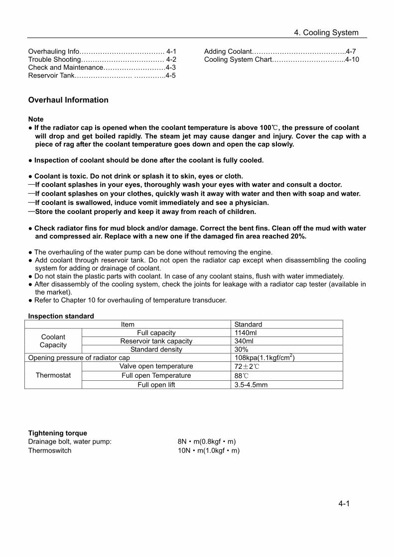
the market). Refer to Chapter 10 for overhauling of temperature transducer. Inspection standard
Item Standard Full capacity 1140ml
Reservoir tank capacity 340ml Coolant Capacity Standard density 30%
Opening pressure of radiator cap 108kpa(1.1kgf/cm2) Valve open temperature 72±2 Full open Temperature 88 Thermostat
Full open lift 3.5-4.5mm Tightening torque Drainage bolt, water pump: 8N·m(0.8kgf·m) Thermoswitch 10N·m(1.0kgf·m)
4-1
4. Cooling System
Trouble Shooting Sharp rise of water temperature
Faulty radiator cap Air in cooling system Faulty water pump Faulty thermostat (thermostat is not open) Clogged radiator pipe or cooling pipes Damage or clogged radiator fin Coolant is not enough Faulty or malfunction of fan motor
No rise or slow rise of water temperature.
Faulty thermostat (thermostat is not closed) Faulty circuit of water temperature display
Coolant leakage
Faulty water seal O-rings are aged, damaged or improperly sealed. Washers are aged, damaged or improperly sealed. Improper installation of pipes or hoses Pipes and/or hoses are aged, damaged or improperly sealed
4-2
4. Cooling System
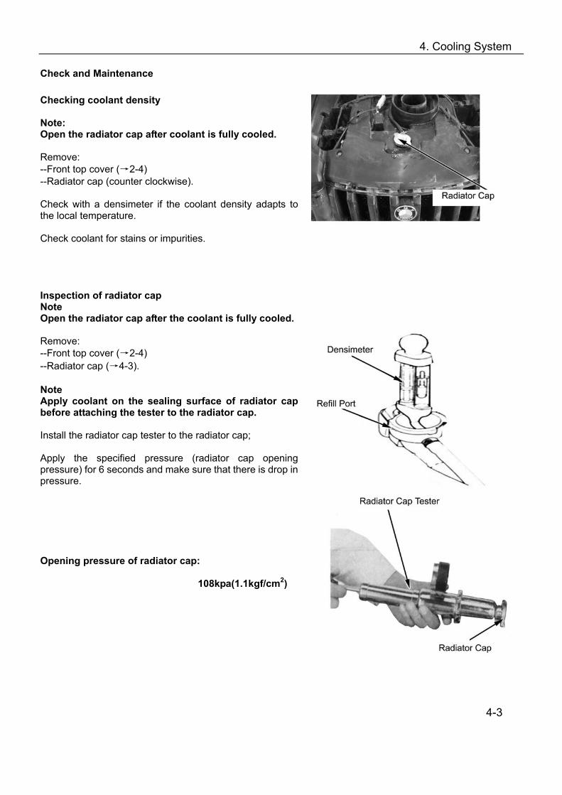
Check and Maintenance Checking coolant density Note: Open the radiator cap after coolant is fully cooled. Remove: --Front top cover (→2-4) --Radiator cap (counter clockwise). Check with a densimeter if the coolant density adapts to the local temperature. Check coolant for stains or impurities. Inspection of radiator cap Note Open the radiator cap after the coolant is fully cooled. Remove: --Front top cover (→2-4) --Radiator cap (→4-3). Note Apply coolant on the sealing surface of radiator cap before attaching the tester to the radiator cap. Install the radiator cap tester to the radiator cap; Apply the specified pressure (radiator cap opening pressure) for 6 seconds and make sure that there is drop in pressure. Opening pressure of radiator cap:
108kpa(1.1kgf/cm2)
4-3
4. Cooling System
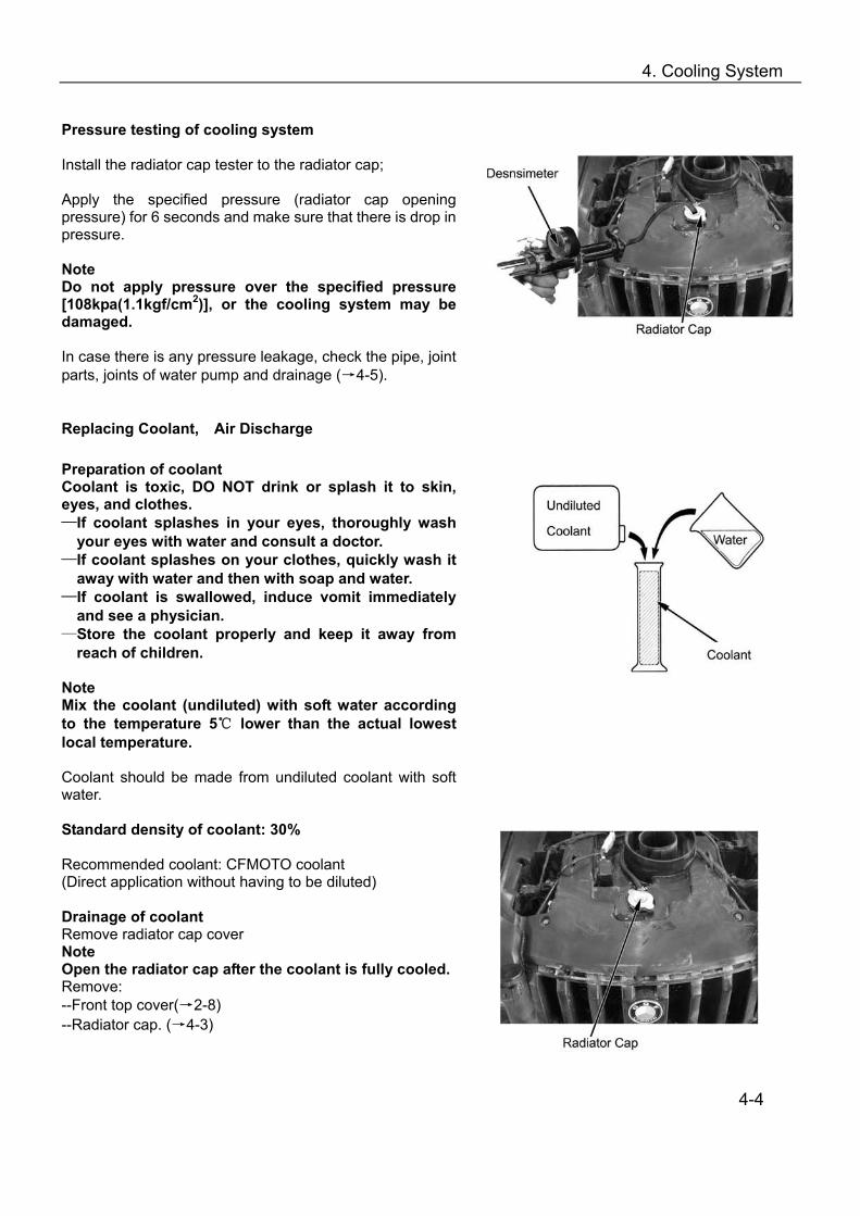
Pressure testing of cooling system Install the radiator cap tester to the radiator cap; Apply the specified pressure (radiator cap opening pressure) for 6 seconds and make sure that there is drop in pressure. Note Do not apply pressure over the specified pressure [108kpa(1.1kgf/cm2)], or the cooling system may be damaged. In case there is any pressure leakage, check the pipe, joint parts, joints of water pump and drainage (→4-5). Replacing Coolant, Air Discharge Preparation of coolant Coolant is toxic, DO NOT drink or splash it to skin, eyes, and clothes. —If coolant splashes in your eyes, thoroughly wash
your eyes with water and consult a doctor. —If coolant splashes on your clothes, quickly wash it
away with water and then with soap and water. —If coolant is swallowed, induce vomit immediately
and see a physician. —Store the coolant properly and keep it away from
reach of children. Note Mix the coolant (undiluted) with soft water according to the temperature 5 lower than the actual lowest local temperature. Coolant should be made from undiluted coolant with soft water. Standard density of coolant: 30% Recommended coolant: CFMOTO coolant (Direct application without having to be diluted) Drainage of coolant Remove radiator cap cover Note Open the radiator cap after the coolant is fully cooled. Remove: --Front top cover(→2-8) --Radiator cap. (→4-3)
4-4
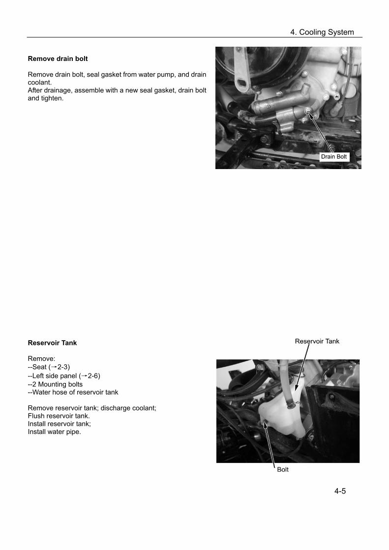
4. Cooling System
Remove drain bolt Remove drain bolt, seal gasket from water pump, and drain coolant. After drainage, assemble with a new seal gasket, drain bolt and tighten. Reservoir Tank Remove: --Seat (→2-3) --Left side panel (→2-6) --2 Mounting bolts --Water hose of reservoir tank Remove reservoir tank; discharge coolant; Flush reservoir tank. reservoir tank Install reservoir tank; bolt Install water pipe.
4-5

4. Cooling System
Adding Coolant Add coolant through filling port. filling port Start the engine and discharge air from cooling system. Check from filling port that air is fully discharged from cooling system and install the radiator cap. Remove reservoir tank cap and add coolant till the upper limit. Note: UPPER LIMIT Check coolant level when the vehicle is on an even ground. LOWER LIMIT Air Discharge Discharge the air from cooling system according to the following steps: 1. Remove drain bolt (→4-5), discharge air and install it. 2. Start the engine and run it several minutes at idle
speed; 3. Quickly increase throttle 3~4 times to discharge air
from cooling system; 4. Add coolant till filling port; 5. Repeat step 2 & 3 till no more coolant can be refilled; 6. Check coolant level in reservoir tank and refill till upper
limit. 7. Install reservoir tank cap.
4-6
4. Cooling System
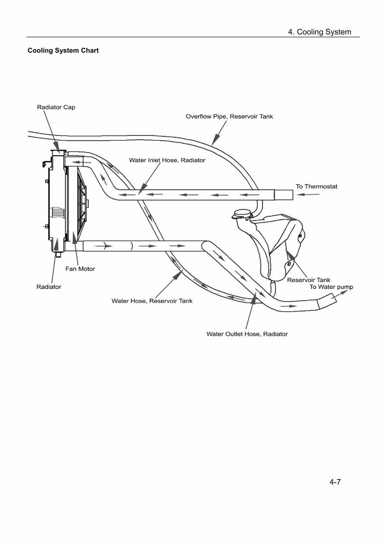
Cooling System Chart
4-7

5. Removal and Installation of Engine, Drive Train and Gearshift Unit
Overhaul Info…..……………………………..5-1 Engine Removal and Installation…………...5-2
Removal and Installation of Front and Rear Axle……………………………………………….5-5 Removal and Installation of Gearshift Unit……5-7
Overhaul info Operation cautions Securely support the ATV with bracket when removing or installing engine.
Take care not to damage frame, engine body, bolts and cables.
Wrap the frame to avoid any possible damage when removing or installing the engine.
Following operation doesn’t require removal of engine from the vehicle:
—Oil pump
—Carburetor, air filter
—Cylinder head cover, cylinder head, cylinder body, camshaft
—CVT system, CVT cover
—Gearbox
—Right side cover, AC magneto, water pump
—Piston, piston ring, piston pin
Following operation require removal of engine from vehicle:
—Crankshaft
Tightening torque:
Engine front upper mounting bolt: 35N~45N·m
Engine front rear mounting bolt: 40~50N·m
Bolt, engine front rear mounting bracket 35~45N·m
Bolt, engine front upper mounting bracket 35~45N·m
5-1
5. Removal and Installation of Engine, Drive Train and Gearshift Unit
Engine Removal
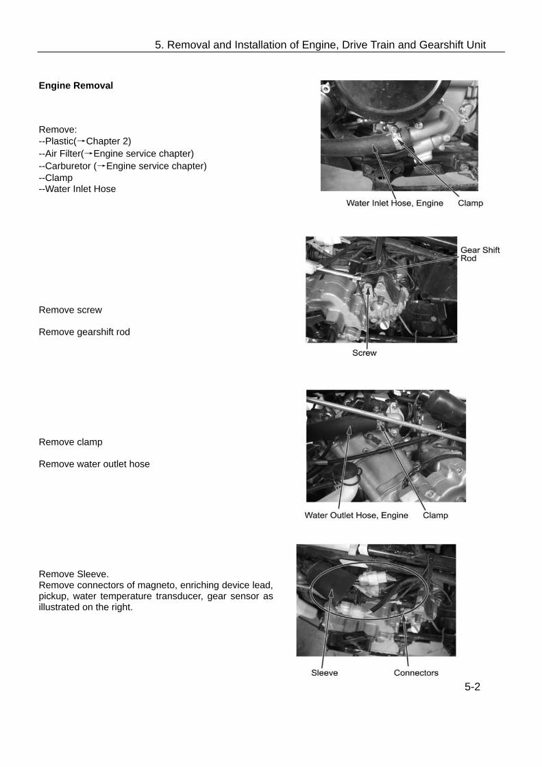
Remove: --Plastic(→Chapter 2) --Air Filter(→Engine service chapter) --Carburetor (→Engine service chapter) --Clamp --Water Inlet Hose Remove screw Remove gearshift rod Remove clamp Remove water outlet hose Remove Sleeve. Remove connectors of magneto, enriching device lead, pickup, water temperature transducer, gear sensor as illustrated on the right.
5-2
5. Removal and Installation of Engine, Drive Train and Gearshift Unit
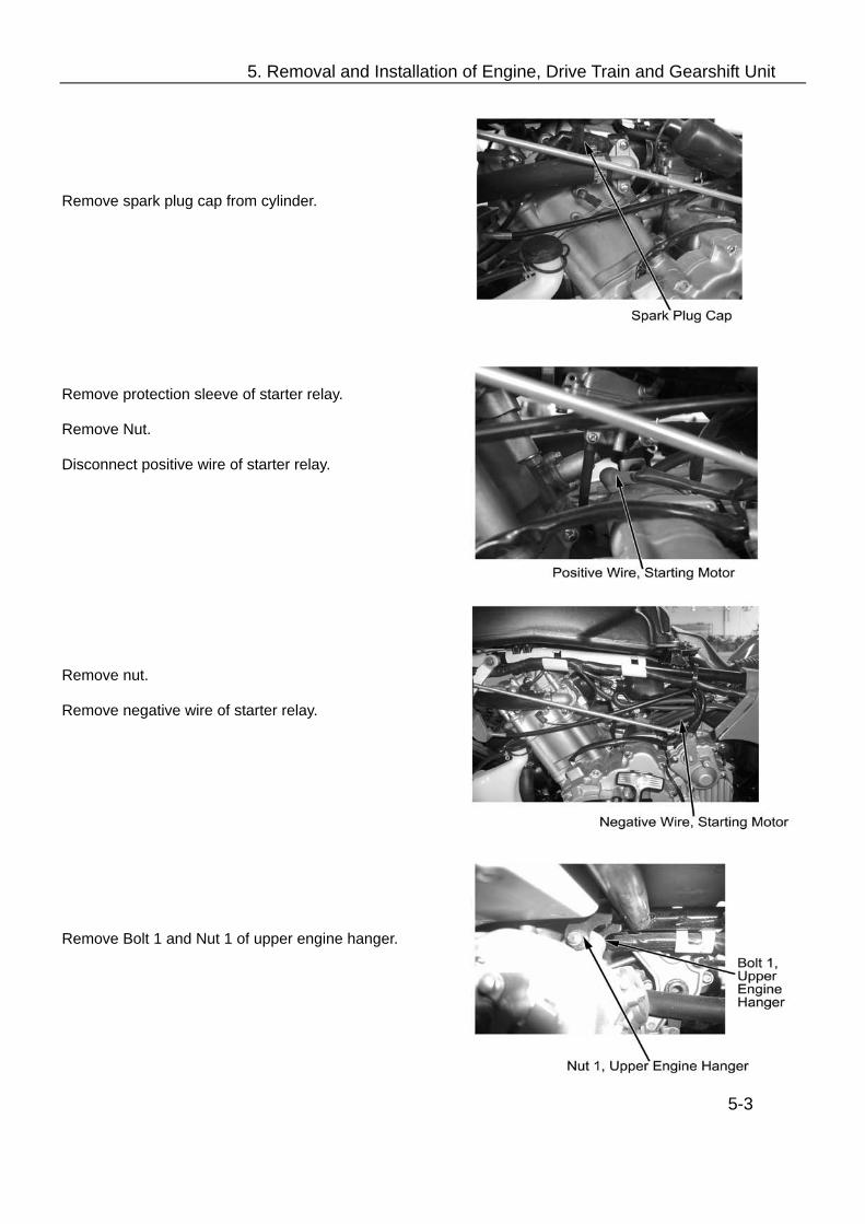
Remove spark plug cap from cylinder.
Remove protection sleeve of starter relay. Remove Nut. Disconnect positive wire of starter relay.
Remove nut. Remove negative wire of starter relay.
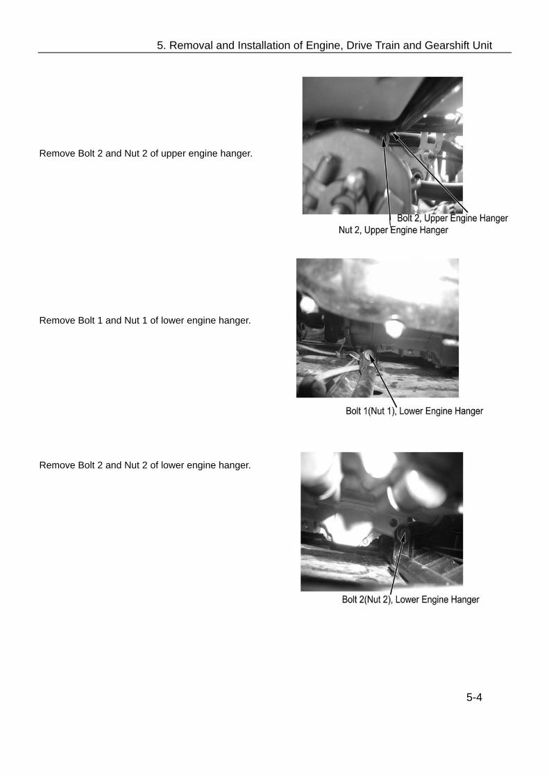
Remove Bolt 1 and Nut 1 of upper engine hanger.
5-3
5. Removal and Installation of Engine, Drive Train and Gearshift Unit
Remove Bolt 2 and Nut 2 of upper engine hanger. Remove Bolt 1 and Nut 1 of lower engine hanger. Remove Bolt 2 and Nut 2 of lower engine hanger.
5-4

5. Removal and Installation of Engine, Drive Train and Gearshift Unit
Engine Installation Put engine onto the frame,install the two lower mounting bolts and nuts. Then install the upper and lower engine hangers.
Tightening torque: Engine upper hanger bolt:35~45N.m Engine lower hanger bolt:50~60N.m
Install: --Water outlet and inlet hoses to engine with proper clamps. --Positive and negative starting wires to engine. --Connect all the connectors. --Spark plug cap. --Gearshift rod to engine. --Air filter, carburetor and removed parts. Removal and Installation of Front and Rear Axle Support the vehicle with jack, make sure the vehicle will not fall. Remove: --Plastic parts for frame(→Chapter 2) --Front and rear wheels and arms(→Chapter 6) --Air filter(→engine service chapter) --Carburetor(→engine service chapter) --Engine --Rear brake caliper(→7-4)
1. Nut 2. Bolt 1 3. Bolt 2 4. Front Axle 5. Bolt 3 6. Front Drive Shaft 7. Clamp 8. Breather Hose, Front Axle 9. Bolt 4 10. Rear Axle 11. Breather Hose, Rear Axle 12. Rear Brake Disk 13. Bolt 5 14. Rear Drive Shaft 5-5

5. Removal and Installation of Engine, Drive Train and Gearshift Unit
Remove nut and bolt of front axle from frame.
Remove nut and bolt of rear axle from frame.
5-6

5. Removal and Installation of Engine, Drive Train and Gearshift Unit
Remove the 18 bolts for drive shafts and front and rear axles. (Refer to P. 5-5, Bolt 3 of Part No.5) Remove: --Front and rear axles, drive shafts, rear brake disc
Installation: Reverse the removal procedure for installation. Tightening torque: Bolt, front axle:40-50N.m Bolt, rear axle:40-50N.m Bolt, front and rear drive shafts:40-50N.m Gearshift Unit Remove: --Left and right side panel(→2-6) --Fuel tank top cover (→2-8) --Front fender(→2-8) --Bolt 1 --Gearshift rod Remove the 2 bolts Remove gearshift unit Installation: Reverse the removal procedure for installation. Make sure that gearshift is flexible. In case of any inflexibility, adjust the gearshift rod to ensure the gear engagement.
5-7

6. Front Wheel, Front Brake, Suspension, Steering
Overhaul Info………………………..…………6-1 Troubleshooting ………………………………6-2 Front Wheel ………………………….………. 6-3
Front Brake…………………….…………..6-4 Suspension…………………………………6-7 Steering ………………………….…………6-12
Overhaul Information Operating cautions Notes Securely support the vehicle when overhauling the front wheel and suspension system. Refer to chapter 10 for overhaul and inspection of lighting, instruments and switches. Do not overexert on the wheel. Avoid any damage to the wheel. When removing tire, use the special tire lever and rim protector. Maintenance Standard
Item Standard Service Limit
Longitudinal 0.8mm 2.0mm Rim Vibration Lateral 0.8mm 2.0mm
Remained groove -- 3.0mm
Tire Tire Pressure 35kpa(0.35kgf/cm2) --
Front brake Free play (brake lever) 0mm -- Tightening torque Nut, Tie-rod 40-50N.m Lock nut, steering stem 110-120N.m Nut, front wheel axle 110N.m Fixing bolt/nut, absorber 40-50N.m Nut, front rim 50-60N.m Nut, front wheel axle 110-130N.m
6-1

6. Front Wheel, Front Brake, Suspension, Steering
Special tools Rod, bearing remover Head 10mm, bearing remover Handle A , Driving Tool Sleeve, Driving Tool 28x30 Guide tool 10mm Locknut spanner Bearing remover set Rotor puller Remover shaft Remover hammer Assembling tool shaft Troubleshooting Heavy Steering
Upper thread is over tightened Steering bearing is damaged or worn Inner & outer bearing races are damaged, worn
or stepped Steering stem is distorted Tire pressure is too low Low tire pressure Worn tire
Shaking Handlebar Steering bearing is damaged, or not well
tightened Right and left shock absorbers are not matched Deflected tires Deformed frame Worn tires Shaking of wheel bearing
Vibration of Front Wheel Wheel rim distorted Faulty wheel bearing Faulty tire
Wheel Cannot Turn Freely Steering bearing is damaged or worn. Front wheel axle is bended Brake drag
Front Suspension Is Too Soft
Weakened front shock absorbers Tire pressure is too low
Front Suspension Is Too Hard
Front shock absorber is bended Tire pressure is too high
Noise With Front Absorbers
Faulty front shock absorbers Loosened tightening parts of front shock
absorbers Poor Brake Efficiency
Faulty brake adjustment Stained brake disc Worn brake shoes
Improper tightening of wheel axle Improper balance of wheels
6-2

6. Front Wheel, Front Brake, Suspension, Steering
Front wheel Removal Securely support the front wheels Remove: -- Wheel cap. --4 bolt from wheel hub --Front wheel. Inspection Rim Damage, warpage or serious scrapes:→ Replace Replace with a new one, if any. Slowly turn the wheel, measure the rim vibration with a dial gauge. Service limit: Axial: 2.0mm Radial: 2.0mm Assembling: Press rim into wheel. Install rim on the wheel hub. Tightening Torque: Bolt, Wheel hub: 50-60 N.m Front Wheel Hub
Disassembly Remove: --Front wheel(→6-3) --Front brake caliper(→6-4) --Rim axle nut --Brake disc and wheel hub --4 bolts of front brake disc --Wheel hub Installation Reverse the removal procedure for installation Torque, Rim axle nut: 110-130N.m
6-3
6. Front Wheel, Front Brake, Suspension, Steering
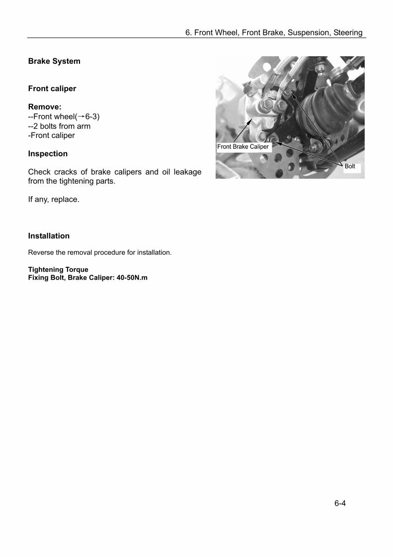
Brake System Front caliper Remove: --Front wheel(→6-3) --2 bolts from arm -Front caliper Inspection Check cracks of brake calipers and oil leakage from the tightening parts. If any, replace. Installation Reverse the removal procedure for installation. Tightening Torque Fixing Bolt, Brake Caliper: 40-50N.m
6-4
6. Front Wheel, Front Brake, Suspension, Steering
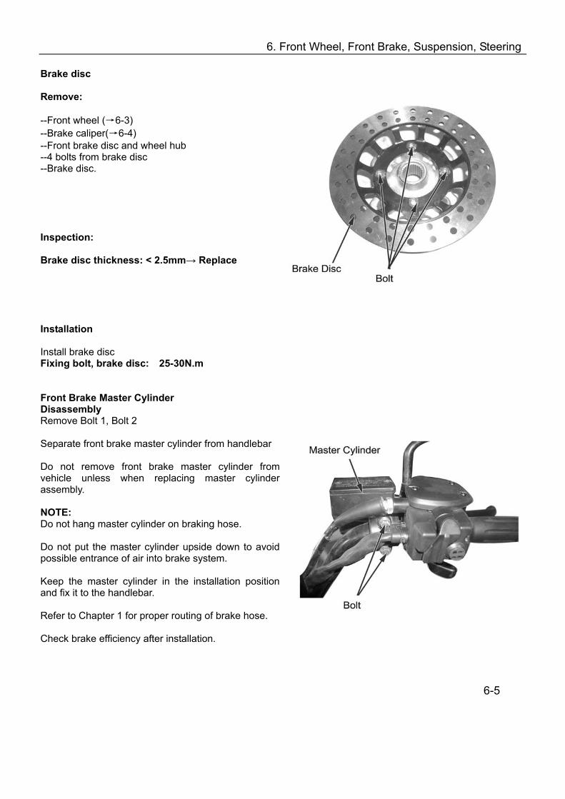
Brake disc Remove: --Front wheel (→6-3) --Brake caliper(→6-4) --Front brake disc and wheel hub --4 bolts from brake disc --Brake disc. Inspection: Brake disc thickness: < 2.5mm→ Replace
Installation Install brake disc Fixing bolt, brake disc: 25-30N.m Front Brake Master Cylinder Disassembly Remove Bolt 1, Bolt 2 Separate front brake master cylinder from handlebar Do not remove front brake master cylinder from vehicle unless when replacing master cylinder assembly. NOTE: Do not hang master cylinder on braking hose. Do not put the master cylinder upside down to avoid possible entrance of air into brake system. Keep the master cylinder in the installation position and fix it to the handlebar. Refer to Chapter 1 for proper routing of brake hose. Check brake efficiency after installation.
6-5
6. Front Wheel, Front Brake, Suspension, Steering
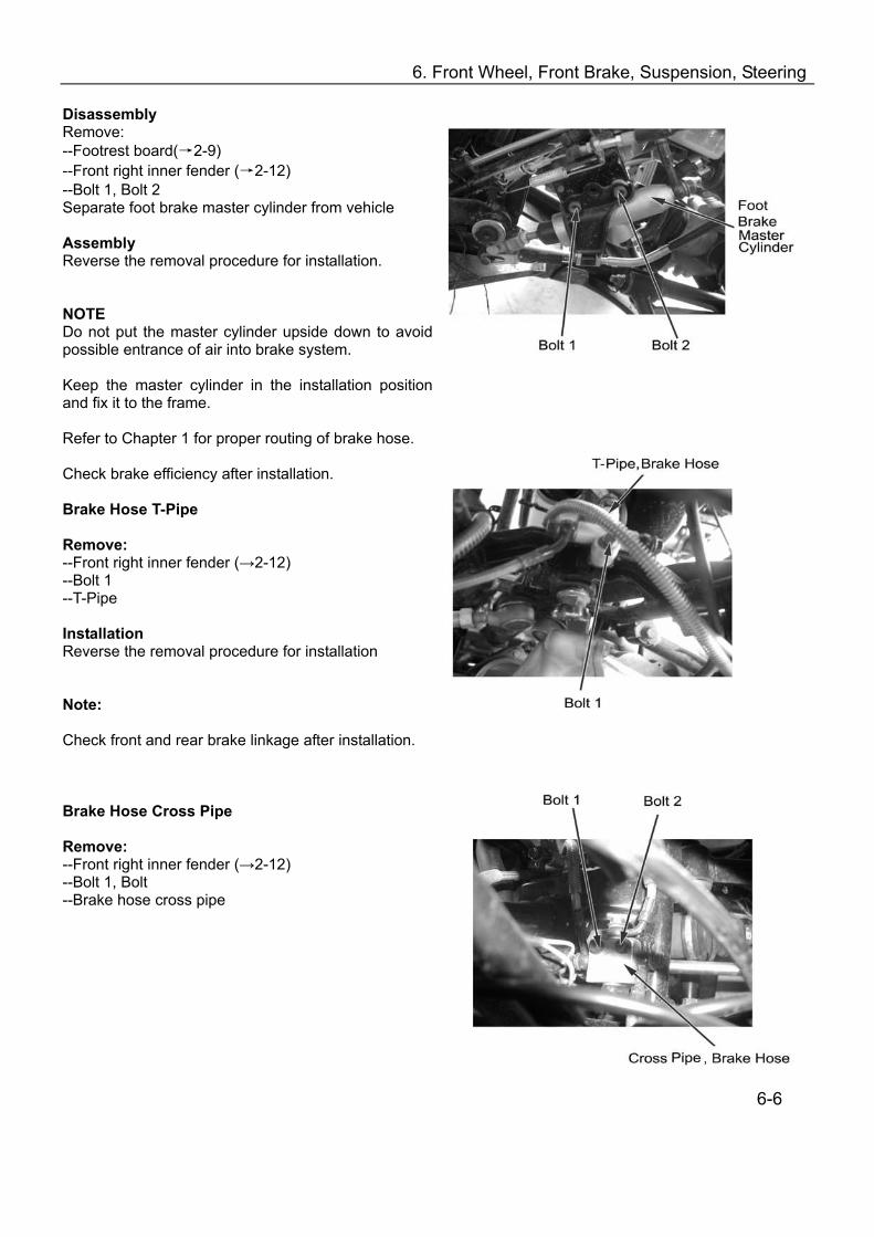
Disassembly Remove: --Footrest board(→2-9) --Front right inner fender (→2-12) --Bolt 1, Bolt 2 Separate foot brake master cylinder from vehicle Assembly Reverse the removal procedure for installation. NOTE Do not put the master cylinder upside down to avoid possible entrance of air into brake system. Keep the master cylinder in the installation position and fix it to the frame. Refer to Chapter 1 for proper routing of brake hose. Check brake efficiency after installation. Brake Hose T-Pipe Remove: --Front right inner fender (→2-12) --Bolt 1 --T-Pipe Installation Reverse the removal procedure for installation Note: Check front and rear brake linkage after installation. Brake Hose Cross Pipe Remove: --Front right inner fender (→2-12) --Bolt 1, Bolt --Brake hose cross pipe
6-6
6. Front Wheel, Front Brake, Suspension, Steering
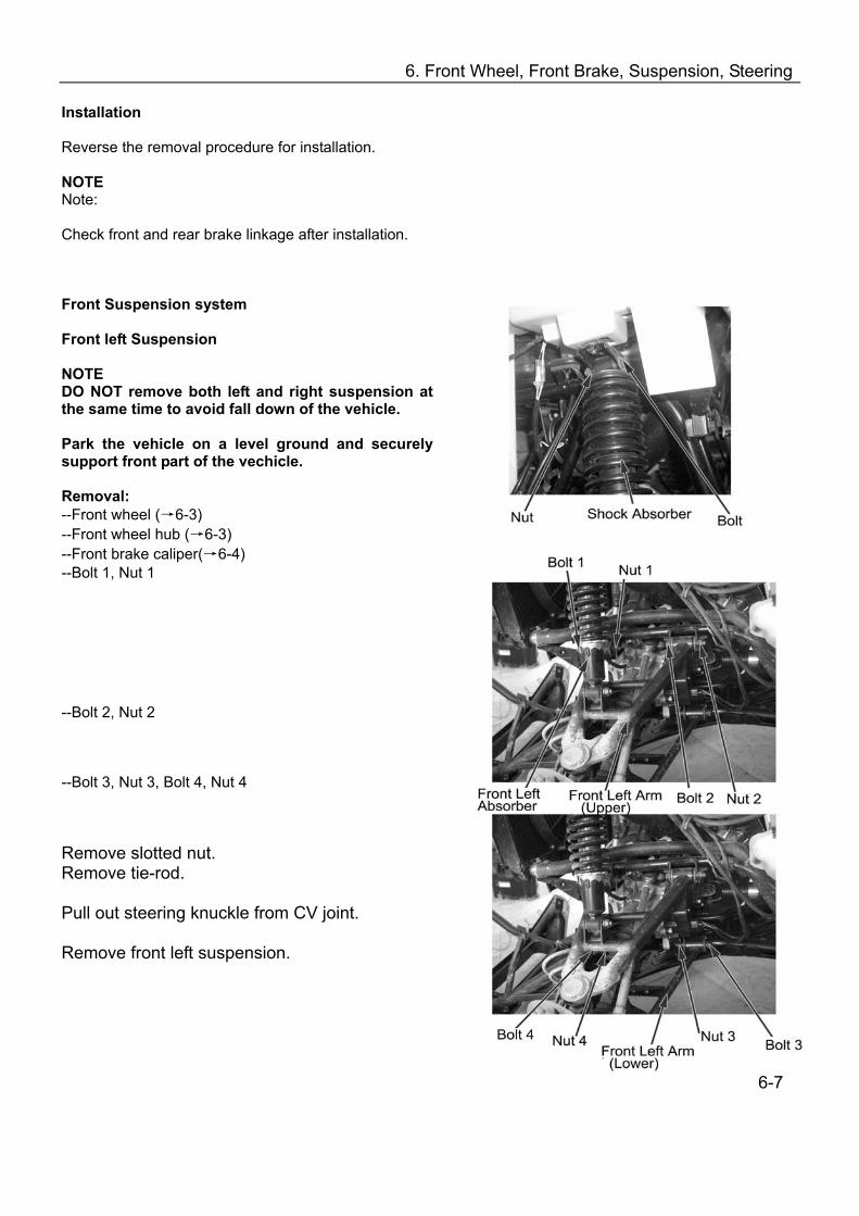
Installation Reverse the removal procedure for installation. NOTE Note: Check front and rear brake linkage after installation. Front Suspension system Front left Suspension NOTE DO NOT remove both left and right suspension at the same time to avoid fall down of the vehicle. Park the vehicle on a level ground and securely support front part of the vechicle. Removal: --Front wheel (→6-3) --Front wheel hub (→6-3) --Front brake caliper(→6-4) --Bolt 1, Nut 1 --Bolt 2, Nut 2 --Bolt 3, Nut 3, Bolt 4, Nut 4 Remove slotted nut. Remove tie-rod. Pull out steering knuckle from CV joint. Remove front left suspension.
6-7
6. Front Wheel, Front Brake, Suspension, Steering
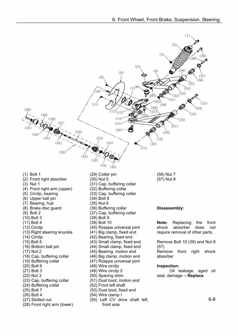
(1) Bolt 1 (2) Front right absorber (3) Nut 1 (4) Front right arm (upper) (5) Circlip, bearing (6) Upper ball pin (7) Bearing, hub (8) Brake disc guard (9) Bolt 2 (10) Bolt 3 (11) Bolt 4 (12) Circlip (13) Right steering knuckle (14) Circlip (15) Bolt 5 (16) Bottom ball pin (17) Nut 2 (18) Cap, buffering collar (19) Buffering collar (20) Bolt 6 (21) Bolt 3 (22) Nut 3 (23) Cap, buffering collar (24) Buffering collar (25) Bolt 7 (26) Bolt 4 (27) Slotted nut (28) Front right arm (lower)
(29) Cotter pin (30) Nut 5 (31) Cap, buffering collar (32) Buffering collar (33) Cap, buffering collar (34) Bolt 8 (35) Nut 6 (36) Buffering collar (37) Cap, buffering collar (38) Bolt 9 (39) Bolt 10 (40) Rzeppa universal joint (41) Big clamp, fixed end (42) Bearing, fixed end (43) Small clamp, fixed end (44) Small clamp, fixed end (45) Bearing, motion end (46) Big clamp, motion end (47) Rzeppa universal joint (48) Wire circlip (49) Wire circlip 2 (50) Spacing shim (51) Dust boot, motion end (52) Front left shaft (53) Dust boot, fixed end (54) Wire clamp I (55) Left CV drive shaft left,
front axle
(56) Nut 7 (57) Nut 8 Disassembly: Note: Replacing the front shock absorber does not require removal of other parts. Remove Bolt 10 (39) and Nut 8 (57) Remove front right shock absorber Inspection:
Oil leakage, aged oil seal, damage→ Replace 6-8

6. Front Wheel, Front Brake, Suspension, Steering
Installation: Reverse the removal procedure for installation. Refer to Front Right Shock Absorber for disassembly, installation and inspection of Front Left Absorber. Suspension Arms Note: This vehicle has 8 suspension arms. The removal, disassembly, inspection and installation of the 8 arms are the same. This service manual will only introduce the removal, disassembly, inspection and installation of Front Left Upper Arm, Front Left Lower Arm. Refer to Front Left Upper Arm, Front Left Lower Arm for removal, disassembly, inspection and installation of other suspension arms. Front Right Arm Disassembly Remove: --Front right absorber (→6-8) --Bolt 9 (38) and Nut 7 (56); --Bolt 8 (34) and Nut 5 (30) --Bolt 7 (25) and Nut 3 (22) --Bolt 6 (21) and Nut 2 (17) Remove wheel, brake caliper and wheel hub before removing absorber; Remove tie-rod before removing bolts; Pull out steering knuckle from CV drive shaft before removing front right arm.
Inspection Ball Pin Check if Upper Ball Pin (6) for Front Right Upper Arm (4) and Lower Ball Pin for Front Right Lower Arm (28) can turn freely in all directions. Check clearance of upper and lower ball pins. Clearance out of range, no free turning: → Replace Ball pin Right Steering Knuckle Inspection: Damaged steering knuckle: → Replace Check wheel hub bearing for free turning and clearance. Bearing cannot turn freely or clearance out of range: → Replace 6-9

6. Front Wheel, Front Brake, Suspension, Steering
(1) Bolt 1 (2) Front right absorber (3) Nut 1 (4) Front right arm (upper) (5) Circlip, bearing (6) Upper ball pin (7) Bearing, hub (8) Brake disc guard (9) Bolt 2 (10) Bolt 3 (11) Bolt 4 (12) Circlip (13) Right Steering Knuckle (14) Circlip (15) Bolt 5 (16) Bottom ball pin (17) Nut 2 (18) Cap, buffering collar (19) Buffering collar (20) Bolt 6 (21) Bolt 3 (22) Nut 3
(23) Cap, buffering collar (24) Buffering collar (25) Bolt 7 (26) Bolt 4 (27) Slotted nut (28) Front right arm (lower) (29) Cotter pin (30) Nut 5 (31) Cap, buffering collar (32) Buffering collar (33) Cap, buffering collar (34) Bolt 8 (35) Nut 6 (36) Buffering collar (37) Cap, buffering collar (38) Bolt 9 (39) Bolt 10 (40) Rzeppa universal joint (41) Big clamp, fixed end (42) Bearing, fixed end (43) Small clamp, fixed end (44) Small clamp, fixed end
(45) Bearing, motion end (46) Big clamp, motion end (47) Rzeppa universal joint (48) Wire circlip (49) Wire circlip 2 (50) Spacing shim (51) Dust boot, motion end (52) Front left shaft (53) Dust boot, fixed end (54) Wire clamp I (55) Left CV drive shaft left, front
axle (56) Nut 7 6-10
6. Front Wheel, Front Brake, Suspension, Steering
Constant Velocity Drive Shafts NOTE: The disassembly, inspection and installation of left and right constant velocity drive shafts of
front rear axles are the same. The following will give instruction only on the disassembly, inspection, installation of Left
Constant Velocity Drive Shaft of front axle. Refer to Left Constant Velocity Drive Shaft for disassembly, inspection, installation of other
drive shafts. (55)Left Constant Velocity Drive Shaft, Front Axle Disassembly NOTE: Maintenance of Left Constant Velocity Drive Shaft of front axle only does not require removal of
front suspension. Remove: --Front wheel(→6-3) --Front left brake caliper(→6-4) --Front left wheel hub (→6-3) Check dust boot. Damaged dust boot: → Replace Shake constant velocity drive shaft, check the agility of rzeppa universal joint, free turning of bearing, and any gap between rzeppa constant velocity joint and spline. Stagnated turning, noise, gap with spline: →Replace Warning: An accident may occur if the rzeppa constant velocity joint cannot run freely because of the loss of control of wheel steering. Installation Press ball pin into arm with special tool. Reverse the removal procedure for installation. Note: There should be no rocking or sway with the installed left and right arms. Tightening Torque: 40~50 N•m
6-11
6. Front Wheel, Front Brake, Suspension, Steering
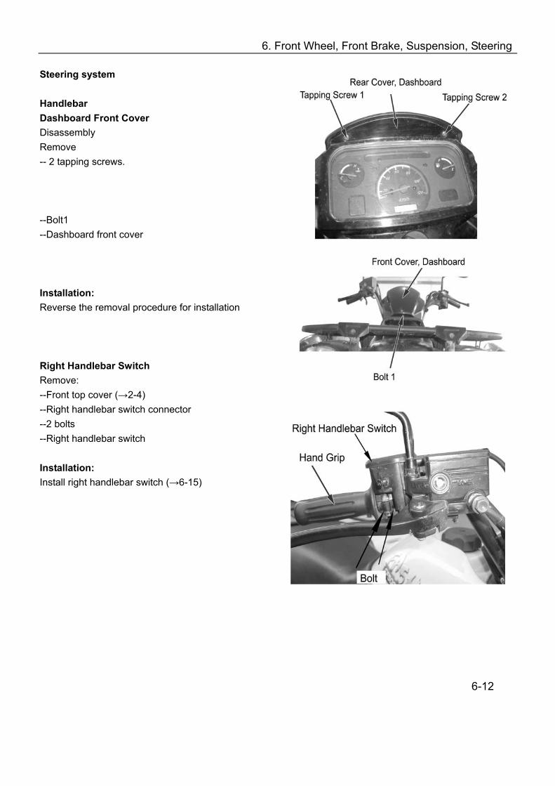
Steering system Handlebar Dashboard Front Cover Disassembly Remove -- 2 tapping screws. --Bolt1 --Dashboard front cover Installation: Reverse the removal procedure for installation Right Handlebar Switch Remove: --Front top cover (→2-4) --Right handlebar switch connector --2 bolts --Right handlebar switch Installation: Install right handlebar switch (→6-15)
6-12
6. Front Wheel, Front Brake, Suspension, Steering
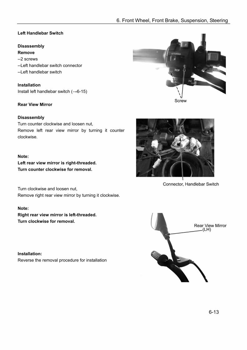
Left Handlebar Switch Disassembly Remove --2 screws --Left handlebar switch connector --Left handlebar switch Installation Install left handlebar switch (→6-15) Rear View Mirror Disassembly Turn counter clockwise and loosen nut, Remove left rear view mirror by turning it counter clockwise.
Note: Left rear view mirror is right-threaded. Turn counter clockwise for removal. Turn clockwise and loosen nut, Remove right rear view mirror by turning it clockwise. Note: Right rear view mirror is left-threaded. Turn clockwise for removal. Installation: Reverse the removal procedure for installation
6-13

6. Front Wheel, Front Brake, Suspension, Steering
Handlebar, Dashboard Rear Cover Disassembly Remove: --Dashboard front cover (→6-12) --Left & right handlebar switch (→6-12)
Separate left & right master cylinders from handlebar Remove: --Screw1, Screw2 --Dashboard rear cover --4 fixing bolts --Handlebar
Installation Reverse the removal procedure for installation Tightening Torque: 20-30N.m (2.0-3.0kgf.m)
Note Main cable, throttle cable, brake hose, cable wiring should be routed properly
Installation of Throttle Cable Remove: --3 screws --Right handlebar top cover Install: --Throttle cable --Right handlebar switch top cover
6-14
6. Front Wheel, Front Brake, Suspension, Steering
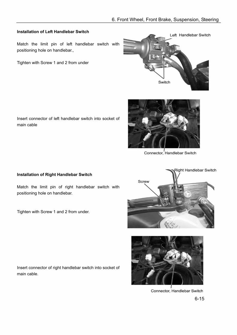
Installation of Left Handlebar Switch Match the limit pin of left handlebar switch with positioning hole on handlebar., Tighten with Screw 1 and 2 from under Insert connector of left handlebar switch into socket of main cable Installation of Right Handlebar Switch Match the limit pin of right handlebar switch with positioning hole on handlebar. Tighten with Screw 1 and 2 from under. Insert connector of right handlebar switch into socket of main cable.
6-15
6. Front Wheel, Front Brake, Suspension, Steering
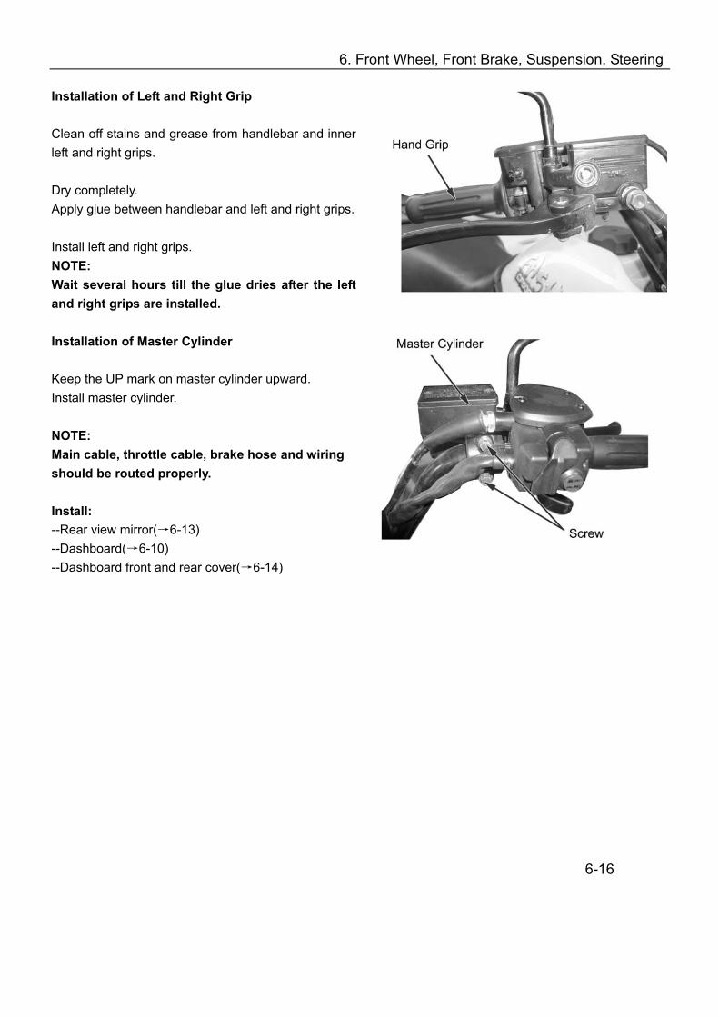
Installation of Left and Right Grip Clean off stains and grease from handlebar and inner left and right grips. Dry completely. Apply glue between handlebar and left and right grips. Install left and right grips. NOTE: Wait several hours till the glue dries after the left and right grips are installed. Installation of Master Cylinder Keep the UP mark on master cylinder upward. Install master cylinder. NOTE: Main cable, throttle cable, brake hose and wiring should be routed properly. Install: --Rear view mirror(→6-13) --Dashboard(→6-10) --Dashboard front and rear cover(→6-14)
6-16
6. Front Wheel, Front Brake, Suspension, Steering
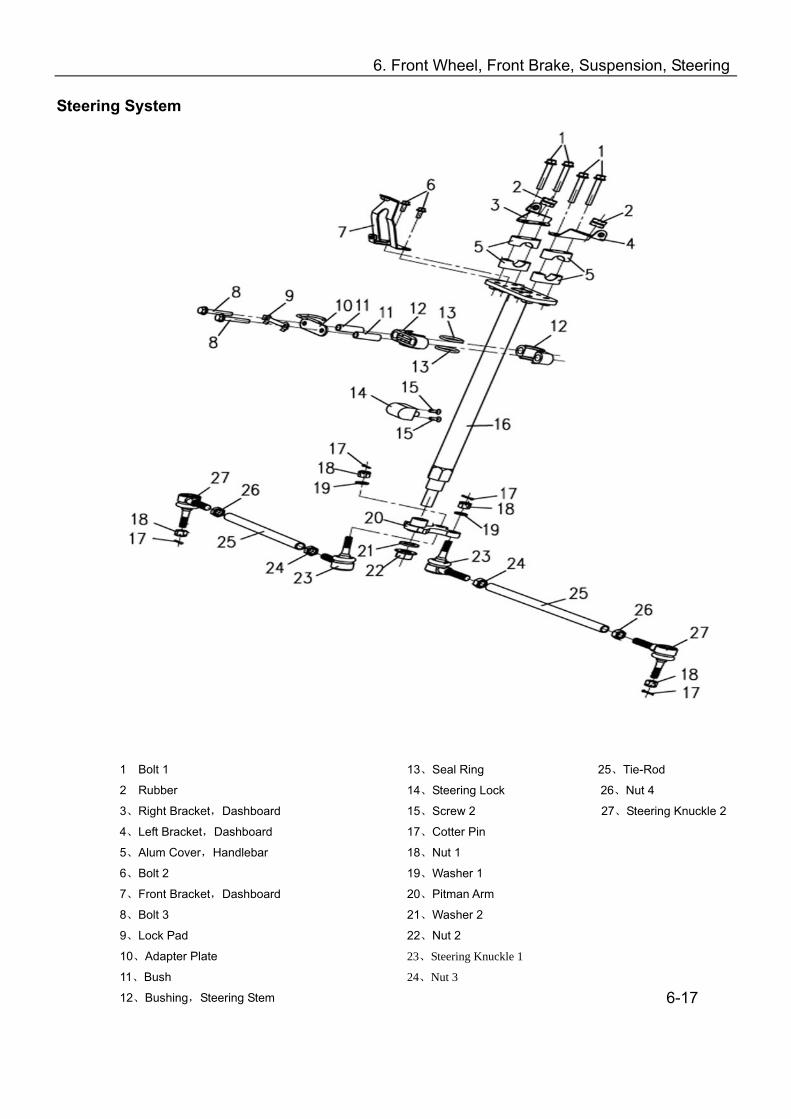
Steering System
1 Bolt 1
2 Rubber
3、Right Bracket,Dashboard
4、Left Bracket,Dashboard
5、Alum Cover,Handlebar
6、Bolt 2
7、Front Bracket,Dashboard
8、Bolt 3
9、Lock Pad
10、Adapter Plate
11、Bush
12、Bushing,Steering Stem
13、Seal Ring 25、Tie-Rod
14、Steering Lock 26、Nut 4
15、Screw 2 27、Steering Knuckle 2
17、Cotter Pin
18、Nut 1
19、Washer 1
20、Pitman Arm
21、Washer 2
22、Nut 2
23、Steering Knuckle 1
24、Nut 3
6-17

6. Front Wheel, Front Brake, Suspension, Steering
Steering Stem Remove: --Dashboard front cover(→6-12) --Front wheel (→6-2) Disconnect handlebar switch connector Hammer the lock pad flat with a flat screwdriver and hammer Remove: -- Bolt 1 and Bolt 2 --Steering stem bushing, adapter plate --Cotter pin --Tie-rod nut and washer Press down steering tie-rod and separate from steering stem Remove fixing bolt of steering stem
Lift steering stem with handlebar from vehicle. Installation: Reverse the removal procedure for installation NOTE: Check steering after installation (3-3) Main cables and wires shall be routed properly (chapter 1)
6-18

6. Front Wheel, Front Brake, Suspension, Steering
Steering Bearing, Oil Seal Remove: --Front wheel (→6-2) --Steering stem (→6-18) Remove front left & right arms(upper & lower)( →6-9) Remove steering bearing and oil seal from frame with special tool Special tools: Bearing removal tool set Rotor puller Removal tool shaft Removal tool hammer Installation Reverse the removal procedure for installation. Special tools: Tool A, Bearing Race Tool shaft Note: Use special tools for installation of bearing. Reverse the removal procedure for installation of the steering system. NOTE: Check steering after installation.
6-19
7. Rear Wheel, Rear Brake, Suspension
Overhaul Info………………………………….. 7-1 Troubleshooting………………………………..7-2 Rear Wheel……………………………………..7-3
Rear Fork………. …………………7-4 Rear Shock Absorber…..…...….. 7-5
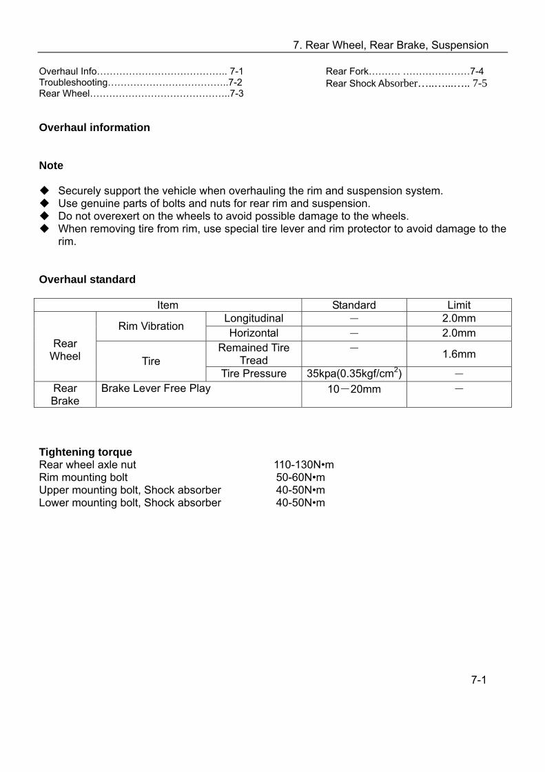
Overhaul information Note
Securely support the vehicle when overhauling the rim and suspension system. Use genuine parts of bolts and nuts for rear rim and suspension. Do not overexert on the wheels to avoid possible damage to the wheels. When removing tire from rim, use special tire lever and rim protector to avoid damage to the
rim. Overhaul standard
Item Standard Limit
Longitudinal - 2.0mm Rim Vibration Horizontal - 2.0mm
Remained Tire Tread
- 1.6mm
Rear Wheel Tire
Tire Pressure 35kpa(0.35kgf/cm2) - Rear Brake
Brake Lever Free Play 10-20mm -
Tightening torque Rear wheel axle nut 110-130N•m Rim mounting bolt 50-60N•m Upper mounting bolt, Shock absorber 40-50N•m Lower mounting bolt, Shock absorber 40-50N•m
7-1
7. Rear Wheel, Rear Brake, Suspension
Troubleshooting Rear Wheel Wobbles
Rim warpage Faulty tire. Tire pressure too low Improper wheel balance Improper tightening of wheel axle nut Loosened wheel nut
Rear Shock Absorber Is Too Soft
Weak spring. Oil leakage from rear shock absorber
Rear Shock Absorber Is Too Hard.
Bent rear shock absorber Tire pressure is too high
Poor Brake Efficiency
Improper brake adjustment Stained brake pad or brake disk Worn or damaged brake pad
7-2
7. Rear Wheel, Rear Brake, Suspension
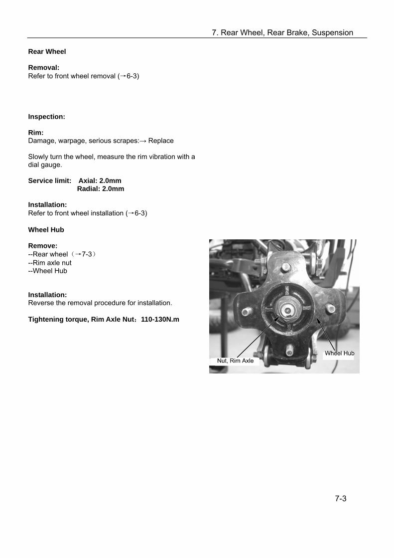
Rear Wheel Removal: Refer to front wheel removal (→6-3) Inspection: Rim: Damage, warpage, serious scrapes:→ Replace Slowly turn the wheel, measure the rim vibration with a dial gauge. Service limit: Axial: 2.0mm Radial: 2.0mm Installation: Refer to front wheel installation (→6-3) Wheel Hub Remove: --Rear wheel(→7-3) --Rim axle nut --Wheel Hub Installation: Reverse the removal procedure for installation. Tightening torque, Rim Axle Nut:110-130N.m
7-3

7. Rear Wheel, Rear Brake, Suspension
Rear Brake Rear Brake Caliper Remove: --Rear left wheel(→7-3) --2 bolts from arm --Brake caliper Inspection: Brake Caliper: Cracks, Oil leakage: →Replace Installation Reverse the removal procedure for installation. Note: Refer to Chapter 1 for brake hose routing. Rear Brake Disc Remove: --Rear left wheel(→7-3) --Rear drive shaft --Rear brake caliper (→7-4) --6 shear bolts --Parking brake(→7-4) --Rear brake disc(→6-3) Inspection Brake Disc: Thickness< 6.5mm: → Replace Installation Reverse the steps of removal for installation. Note: Refer to Chapter 1 for brake hose routing. Parking Brake Remove: --Rear left wheel(→7-3) --Rear drive shaft --Rear brake caliper (→7-4) --6 shear bolts --Parking brake
7-4

7. Rear Wheel, Rear Brake, Suspension
Rear Suspension System Rear Right Suspension NOTE DO NOT remove both left and right suspension at the same time to avoid fall down of the vehicle.
(1) Left Ball Pin (2) Nut 1 (3) Stabilizer Bar (4) Rubber Support, Right Rear Arm (5) Bracket (6) Bolt 1 (7) Bolt 2 (8) Bracket (9) Rubber Support (10) Bolt 3
(11) Bolt 4 (12) Nut 2 (13) Bolt5 (14) Right Ball Pin (15) Nut 3 (16) Bolt 6 (17) Rear Right Upper Arm (18) Rear Right Lower Arm (19) Bolt 7 (20) Bolt 8
(21) Nut 4 (22) Bolt 9 (23) Nut 5 (24) Nut 6 (25)Bolt10 (26) Rear Right Absorber (27) Nut 7 (28) Nut 8
Disassembly Stabilizer Bar Remove: Bolt 1(6), Bolt 2 (7), Bolt 3 (10), Bolt 4 (11), Bracket (8)and(5), Rubber Support (4) and (9), Nut 2 (2), Nut 10 (12), Left Ball Pin (1), Right Ball Pin (14) Remove: Stabilizer Bar (3) Installation: Reverse the removal procedure for installation 7-5
7. Rear Wheel, Rear Brake, Suspension
Right Rear Absorber Removal Note: Securely support the vehicle when removing rear left and right absorbers. Suspend wheels from ground. Maintenance of rear absorbers only does not require removal of rear suspension. Remove the following parts for rear right shock absorber (25) Bolt 10 (27) Nut 7 (19) Bolt 7 (28) Nut 8 Remove rear right shock absorber Installation: Reverse the removal procedure for installation. Rear Right Arm Refer to Front Left Upper Arm in Chapter 13 for the removal, inspection and installation of Rear Right Arm Rear Left Suspension Refer to Rear Right Suspension for the removal, inspection and installation of Rear Left Suspension.
7-6
8. Battery, Charging System
Charging System Layout……………….……. 8-1 Overhaul Info……………………………………8-2 Troubleshooting ……………………..…………8-3 Battery……………………………………………8-4
Inspection of Charging System… ……. 8-5 Rectifier/Regulator……………………….. 8-6 Inspection of AC Magneto………………. 8-8
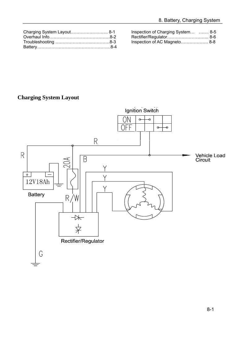
Charging System Layout
8-1
8. Battery, Charging System
Overhaul information Note
Usually no hydrogen will be generated during charging except when overcharged. Keep away from fires when charging.
Electrolyte is highly corrosive, splash to clothes, skin or eyes will cause burn or loss of sight. Wash with plenty of water if splashed. In case of splash into eyes, wash with plenty of water and consult the doctor. The electrolyte on the clothes may contact the skin as well, it will cause damage to the clothes if stained for a long time. Change a clothes and wash away the electrolyte.
Note
Spark arc may be generated when removing or joining the electrical parts with switch on and will damage the electrical parts such as rectifier. Operation should be done with ignition switch OFF.
Remove battery from vehicle for charging and do not open the electrolyte cover. Note Replace if the battery service life expired.
Keep the ignition switch OFF when removing electrical parts. Disconnect the negative connection of battery if it is stored on the vehicle Fast charging is not recommended as it may reduce the battery life. If battery is repeatedly charged and discharged fully (fully-charged and fully-discharged), it
may cause damage to the battery or shorten the service life or lower the capacity of battery. In addition, the capacity of battery will also lower in 2~3 years even under normal use. So the battery should also be replaced.
If the open voltage is less than 12.4V, charge the battery normally to raise the open voltage up to 12.4V.
Refer to troubleshooting table (→8-3) for inspection of charging system Refer to Engine Maintenance for removal and installation of AC magneto Inspection of battery should be done following the owner’s manual of battery tester.
8-2

8. Battery, Charging System
Overhaul standard Item Standard
Model Permanent magnet alternator
Output 3-phase AC AC magneto
Resistance of charging coil (20) 0.2-0.3Ω
Rectifier Type 3-phase loop rectification,
controllable parallel connection, regulated
voltage Capacity 12V10Ah
Current Leakage Less than1mA Fully-charged 12.8V Voltage between
terminals Insufficient charge Less than 11.8V Standard 0.9A/5~10hours
Battery Charging current/time
Fast charge 4A/60minutes Troubleshooting Battery overflow Incorrect Faulty Battery
Correct
Incorrect
Correct
Correct Incorrect →
Incorrect •Faulty rectifier •Short circuit with
• AC magneto has short main cable or open circuit. •Faulty ignition switch
Correct
Correct Charging system is correct.
Incorrect
Incorrect l •Main cable has short/open circuit. •Faulty contact of connectors
Correct
8-3
Check battery with recommended test meter: YUASA ‘ BM310 or equivalent
Measure the current leakage of battery. (→8-5) Current: below 1mA
Inspect the charging coil of AC magneto. Resistance: 0.2-0.3Ω
Inspect monomer voltage of battery and record it. (→8-4) Start engine, turn on headlight with high beam. Inspect battery’s voltage between terminals at the engine speed of 5000rpm. (→8-5) Standard: monomer voltage<charge voltage<15V
Inspect rectifier system (→8-6)
Disconnect rectifier, and measure current leakage again. Current: less than 1mA
8. Battery, Charging System
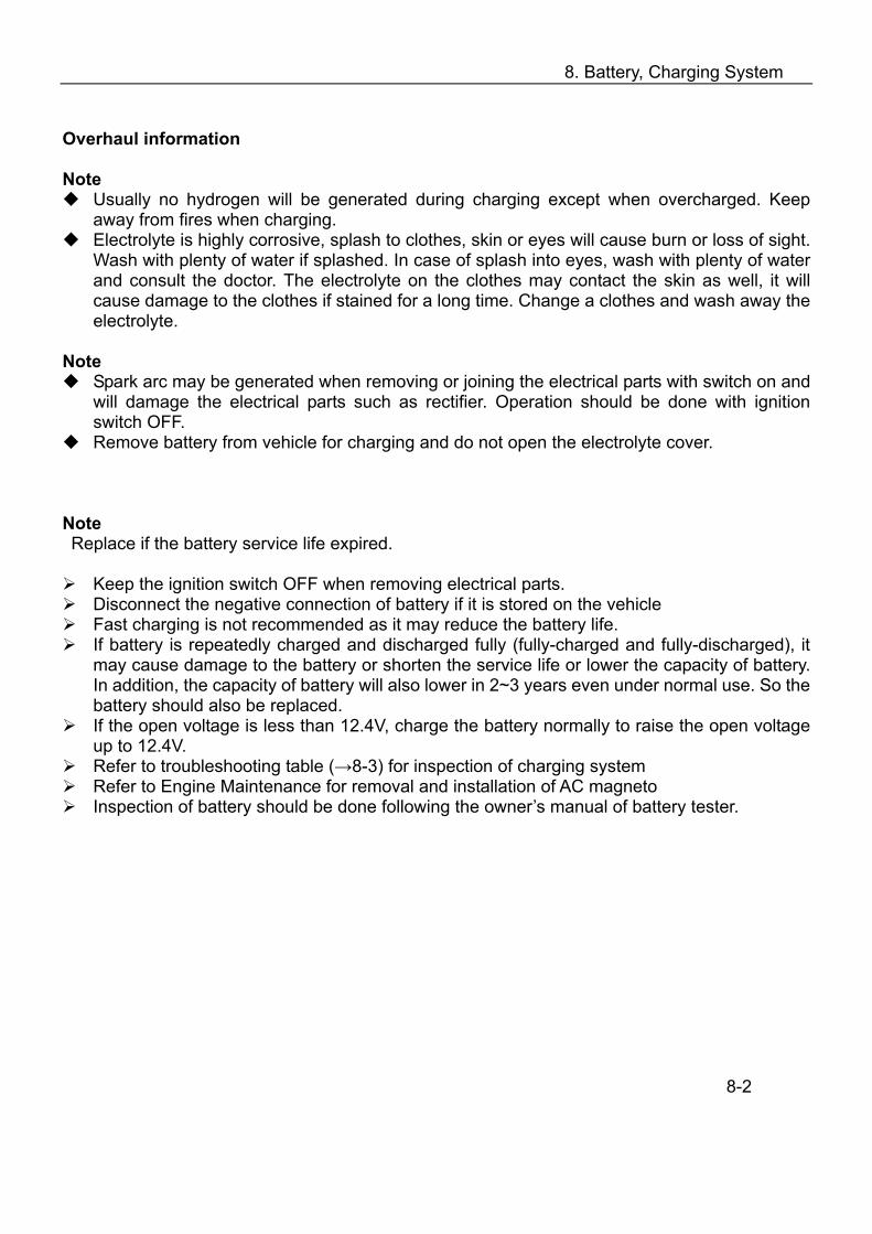
Battery Note: Keep the ignition switch at OFF before operation. Remove: --Seat (→2-3) --Bolt1&Bolt2 --Battery fixing plate --Battery cover Loosen negative pole screw and disconnect negative lead. Remove positive pole cap and screw. Disconnect positive lead.
Installation: Reverse the removal procedure for installation. Note:
Apply clean lubricant grease to the pole after installation.
Install cap firmly on the positive pole after installation.
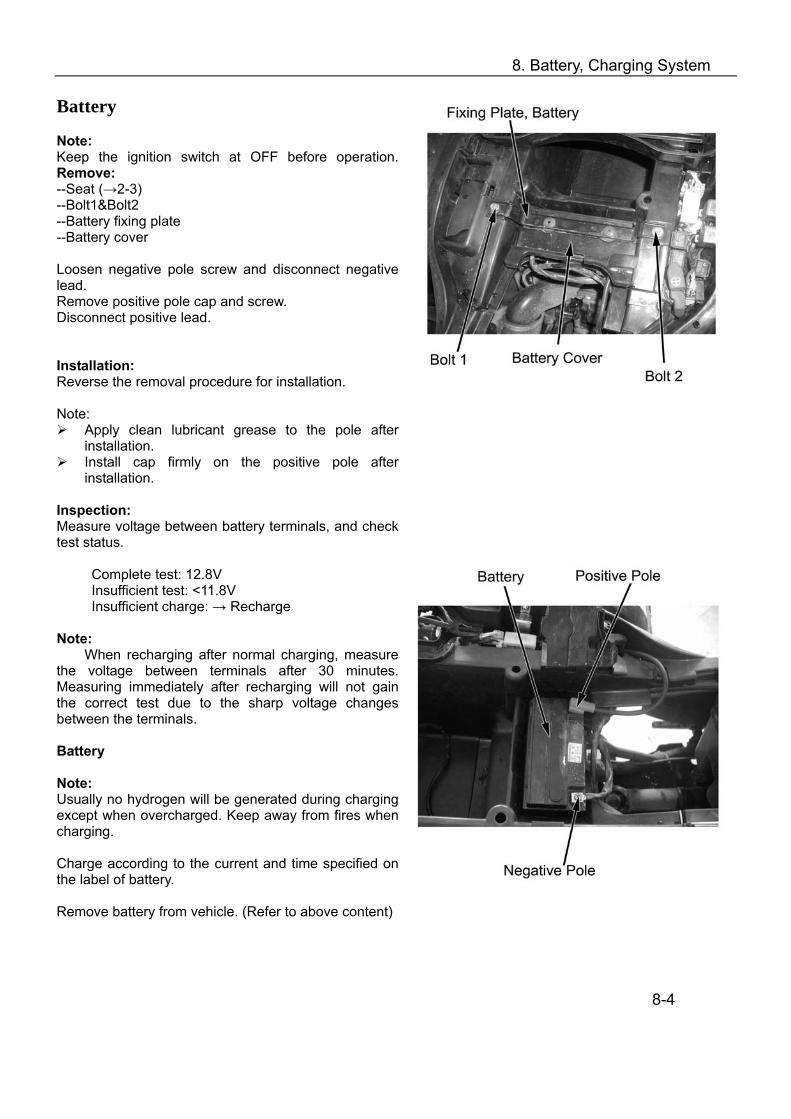
Inspection: Measure voltage between battery terminals, and check test status.
Complete test: 12.8V Insufficient test: <11.8V Insufficient charge: → Recharge
Note:
When recharging after normal charging, measure the voltage between terminals after 30 minutes. Measuring immediately after recharging will not gain the correct test due to the sharp voltage changes between the terminals.
Battery Note: Usually no hydrogen will be generated during charging except when overcharged. Keep away from fires when charging. Charge according to the current and time specified on the label of battery. Remove battery from vehicle. (Refer to above content)
8-4
8. Battery, Charging System
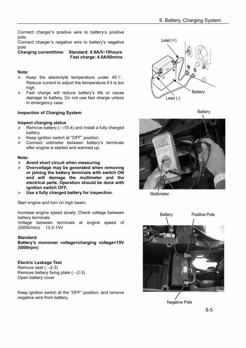
Connect charger’s positive wire to battery’s positive pole. Connect charger’s negative wire to battery’s negative pole. Charging current/time: Standard: 0.9A/5~10hours
Fast charge: 4.0A/60mins
Note:
Keep the electrolyte temperature under 45 . Reduce current to adjust the temperature if it is too high.
Fast charge will reduce battery’s life or cause damage to battery. Do not use fast charge unless in emergency case.
Inspection of Charging System Inspect charging status
Remove battery (→15-4) and install a fully charged battery.
Keep ignition switch at “OFF” position. Connect voltmeter between battery’s terminals
after engine is started and warmed up. Note:
Avoid short circuit when measuring Overvoltage may be generated when removing
or joining the battery terminals with switch ON and will damage the multimeter and the electrical parts. Operation should be done with ignition switch OFF.
Use a fully charged battery for inspection. Start engine and turn on high beam. Increase engine speed slowly. Check voltage between battery terminals. Voltage between terminals at engine speed of (5000r/min): 13.5-15V Standard: Battery’s monomer voltage<charging voltage<15V (5000rpm) Electric Leakage Test Remove seat (→2-3) Remove battery fixing plate (→2-3) Open battery cover Keep ignition switch at the “OFF” position, and remove negative wire from battery.
8-5
8. Battery, Charging System
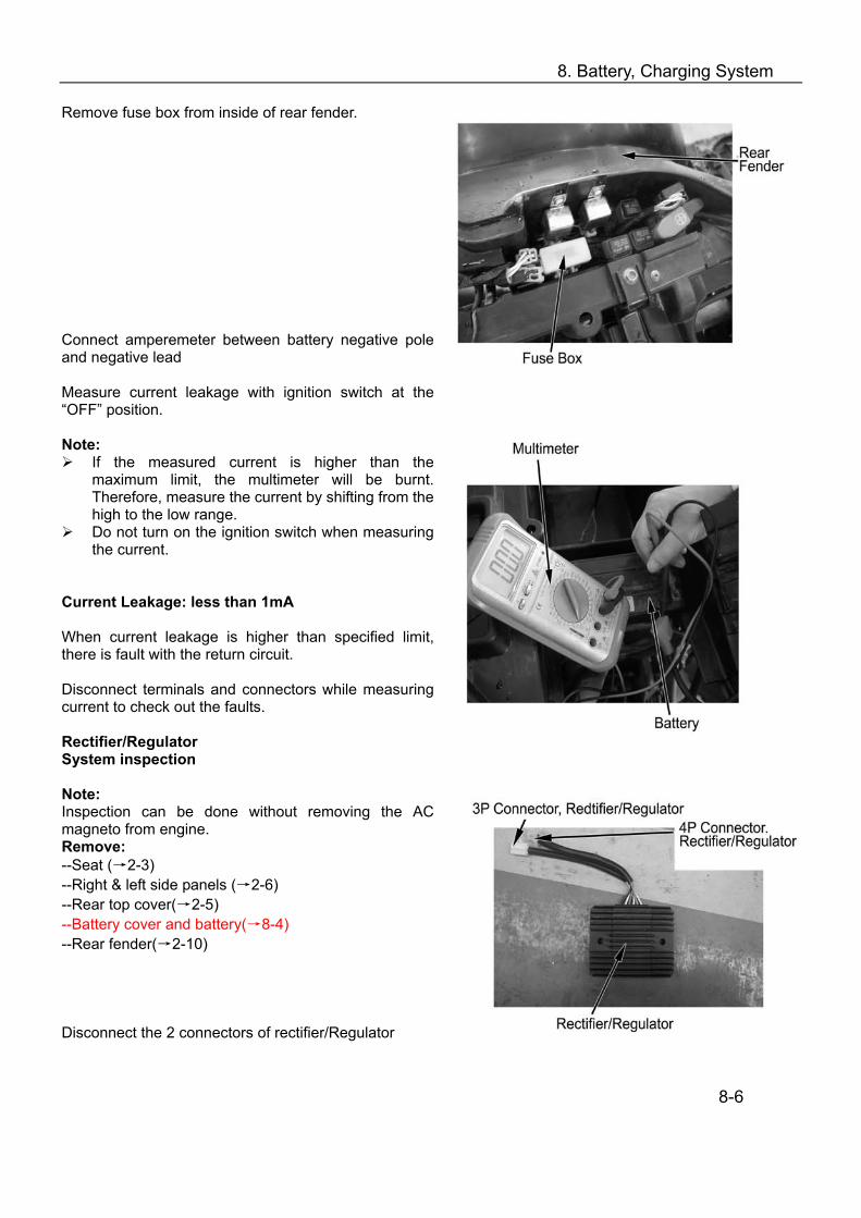
Remove fuse box from inside of rear fender. Connect amperemeter between battery negative pole and negative lead Measure current leakage with ignition switch at the “OFF” position. Note:
If the measured current is higher than the maximum limit, the multimeter will be burnt. Therefore, measure the current by shifting from the high to the low range.
Do not turn on the ignition switch when measuring the current.
Current Leakage: less than 1mA When current leakage is higher than specified limit, there is fault with the return circuit. Disconnect terminals and connectors while measuring current to check out the faults. Rectifier/Regulator System inspection Note: Inspection can be done without removing the AC magneto from engine. Remove: --Seat (→2-3) --Right & left side panels (→2-6) --Rear top cover(→2-5) --Battery cover and battery(→8-4) --Rear fender(→2-10) Disconnect the 2 connectors of rectifier/Regulator
8-6
8. Battery, Charging System
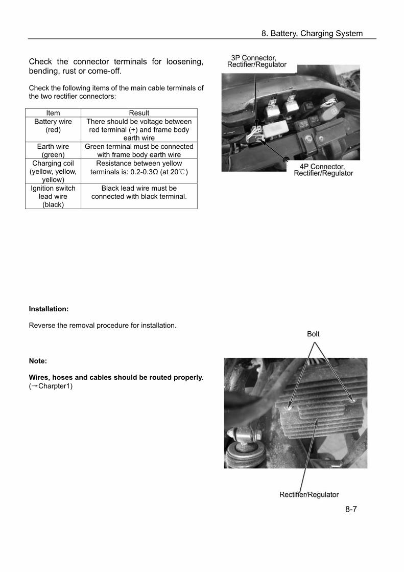
Check the connector terminals for loosening, bending, rust or come-off. Check the following items of the main cable terminals of the two rectifier connectors:
Item Result Battery wire
(red) There should be voltage between red terminal (+) and frame body
earth wire Earth wire
(green) Green terminal must be connected
with frame body earth wire Charging coil
(yellow, yellow, yellow)
Resistance between yellow terminals is: 0.2-0.3Ω (at 20)
Ignition switch lead wire (black)
Black lead wire must be connected with black terminal.
Installation: Reverse the removal procedure for installation. Note: Wires, hoses and cables should be routed properly. (→Charpter1)
8-7
8. Battery, Charging System
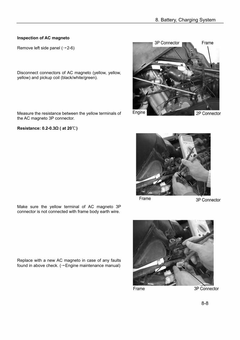
Inspection of AC magneto Remove left side panel (→2-6) Disconnect connectors of AC magneto (yellow, yellow, yellow) and pickup coil (black/white/green). Measure the resistance between the yellow terminals of the AC magneto 3P connector. Resistance: 0.2-0.3Ω ( at 20) Make sure the yellow terminal of AC magneto 3P connector is not connected with frame body earth wire.
Replace with a new AC magneto in case of any faults found in above check. (→Engine maintenance manual)
8-8
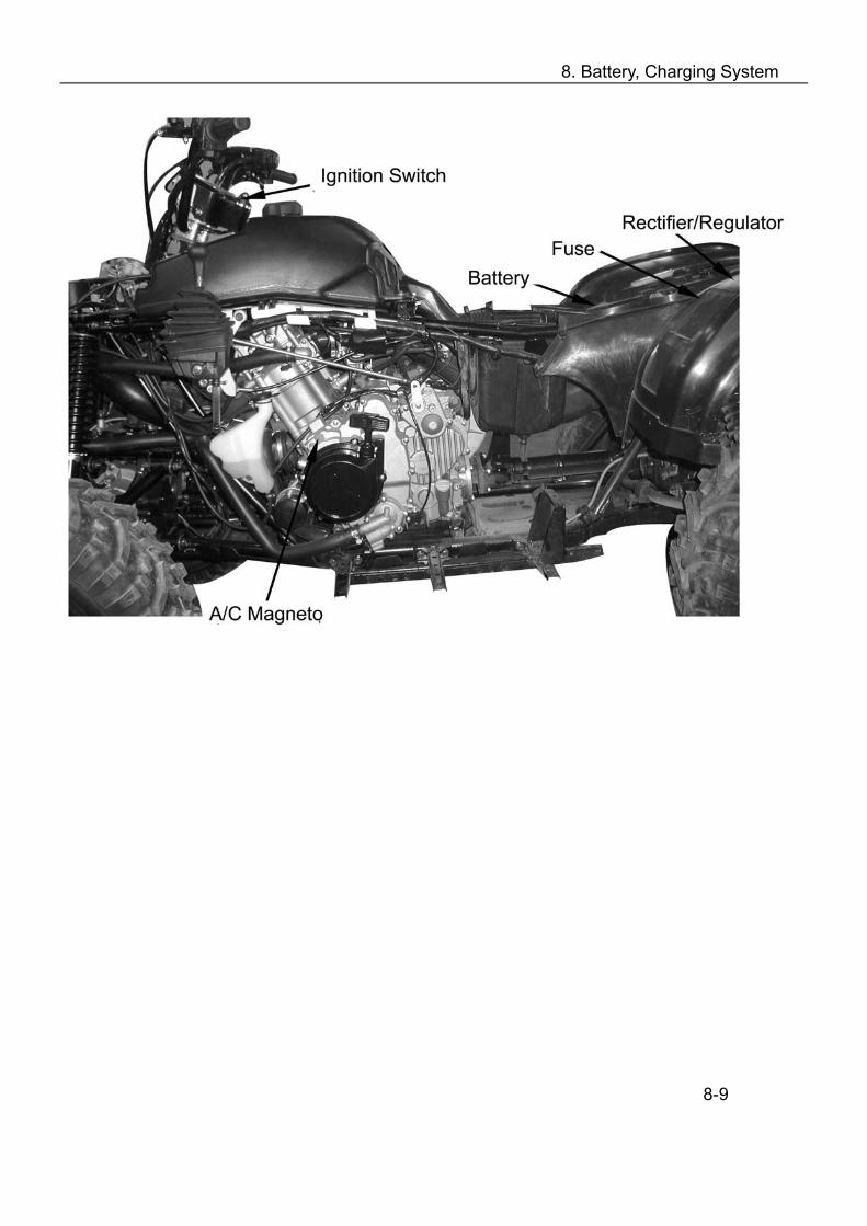
8. Battery, Charging System
8-9

9. Ignition System
Overhaul Info……………………………………..9-1 Troubleshooting……………………….…………9-3 Inspection of Ignition System…………………...9-4
Pickup Coil ………………..………… .…... 9-6 Ignition Coil ……………………... ……….. 9-6 Ignition System Diagram ………………….9-7
Overhaul information Note:
Exhaust gas contains toxicant, DO NOT keep the engine run for a long time in a closed or poorly ventilated place.
Inspect ignition system in the order of the content in troubleshooting table Refer to (9-7) for ignition system diagram Ignition advancer is integrated in the CDI, so the ignition system will automatically adjust
ignition time. Be careful with CDI overhaul. Dropping or strong impact may cause damage to CDI. In
addition, overvoltage may be generated on CDI and cause damage to return circuit when removing or joining the connectors and terminals with switch ON .Always shut the ignition switch when overhauling.
Most of the failures of ignition system are caused by faulty contacts between connectors and terminals. Check all the connections for any faults before overhauling.
Select spark plug of proper heat value. Improper spark plug may cause malfunction or damage of engine.
Refer to Chapter 10 for inspection of switches 9-1

9. Ignition System
Overhaul standard
Item Standard
Ignition CDI, battery DC digital ignition Standard DPR7EA-9(NGK) Optional DR8EA, D7RTC
Spark Plug
Spark plug gap 0.8-0.9mm Ignition timing Maximum advance
angle 34° CA
Ignition coil >200V Peak voltage Impulse generator 4V
Special tool Peak voltage oscillograph 07HGJ-0020100 (Use together with digital muitimeter available in the market with input resistance over 10MΩ/DCV)
9-2
9. Ignition System
Troubleshooting
Engine cannot be started. Check fuel and air channels for any faults; If the fuel and air channels are normal, check the
ignition system. Inspect ignition system for the following items:
1. Spark inspection: Check in the following steps:
Remove spark plug Remove spark plug cap
Set high tension flexible cable end to earth Check spark arc
It is normal if spark arc is more than 8mm,while it is weak if it is less than 5 mm. If the spark is normal, check the spark plug. A faulty spark plug may be caused by the following reasons:
(1) Spark plug is too wet and drowned. This is because the gas mixture is too thick. Cut the fuel and start the engine several times..
(2) Carbon deposit on spark plug---Mixture too thick or oil combustion in the combustion chamber. Clean and burnish the spark plug.
(3) Cracks with spark plug insulator. (4) Spark plug electrodes have short circuit or it is obstructed between negative pole and
thread or positive pole and input end. 2. Faulty spark includes: no spark and weak spark.
Inspect the following aspects if there is no spark. (1). Inspect ignition coil with multimeter or measurement in the following steps:
1) Measure primary bobbin resistance, usually it is about 1Ω. 2) Measure secondary bobbin resistance, usually it is about 4.2K. 3) Measure damp resistance, usually it is about 5K.
(2). Check CDI if it is out of service. (3). Check ignition circuit. Usually the voltage between black wire and earth wire (green) should be 12V. If there is no voltage, check from the battery positive terminal to the end of black wire. (4). Check the cable: check if there are any faults from the input of trigger signal (output of magneto pickup) to output (CDI terminal) and ignition output wire (black/yellow). (5). Check stop switch. When switch is at the ignition position, black/white wire should be cut
with green wire. In case of weak spark, check the following: (1). Check CDI . (2). Check ignition coil and secondary coil whether there is short circuit, or fault with the damp
resistance.
9-3 I
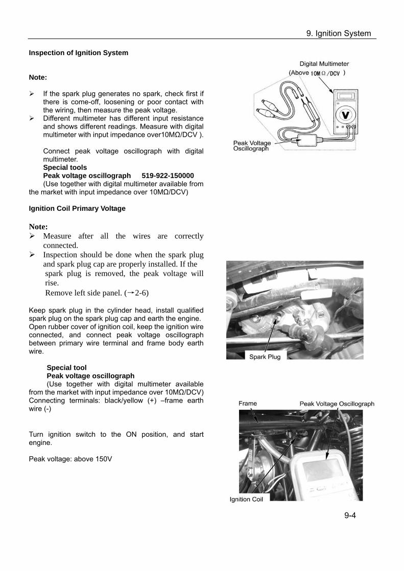
9. Ignition System
Inspection of Ignition System
Note:
If the spark plug generates no spark, check first if
there is come-off, loosening or poor contact with the wiring, then measure the peak voltage.
Different multimeter has different input resistance and shows different readings. Measure with digital multimeter with input impedance over10MΩ/DCV ).
Connect peak voltage oscillograph with digital multimeter. Special tools Peak voltage oscillograph 519-922-150000 (Use together with digital multimeter available from
the market with input impedance over 10MΩ/DCV) Ignition Coil Primary Voltage Note:
Measure after all the wires are correctly connected.
Inspection should be done when the spark plug and spark plug cap are properly installed. If the spark plug is removed, the peak voltage will rise. Remove left side panel. (→2-6)
Keep spark plug in the cylinder head, install qualified spark plug on the spark plug cap and earth the engine. Open rubber cover of ignition coil, keep the ignition wire connected, and connect peak voltage oscillograph between primary wire terminal and frame body earth wire.
Special tool Peak voltage oscillograph (Use together with digital multimeter available
from the market with input impedance over 10MΩ/DCV) Connecting terminals: black/yellow (+) –frame earth wire (-)
Turn ignition switch to the ON position, and start engine. Peak voltage: above 150V
9-4

9. Ignition System
Pickup Coil Note:
Measure after all the wires are correctly connected. Inspect with compression pressure in the cylinder,
spark plug and spark plug cap are properly installed. If the spark plug is removed and then do the measurement, the peak voltage will rise.
Remove left side panel (→2-3) Disconnect CDI unit connector. Connect peak voltage oscillograph terminal with the following terminal of main cable. Special tools Peak voltage oscillograph 07HGJ-0020100 (Use together with digital multimeter available from the market with input impedance over 10MΩ/DCV) Connecting terminal: blue/yellow (+) –green (-) Turn ignition switch to the ON position, and start engine.
Peak voltage: over 0.8V Note: When measuring the voltage, do not touch the terminal with finger to avoid electric shock. If peak voltage obtained from CDI unit connector is improper, measure again the peak voltage on the AC magneto 2P connector.
9-5
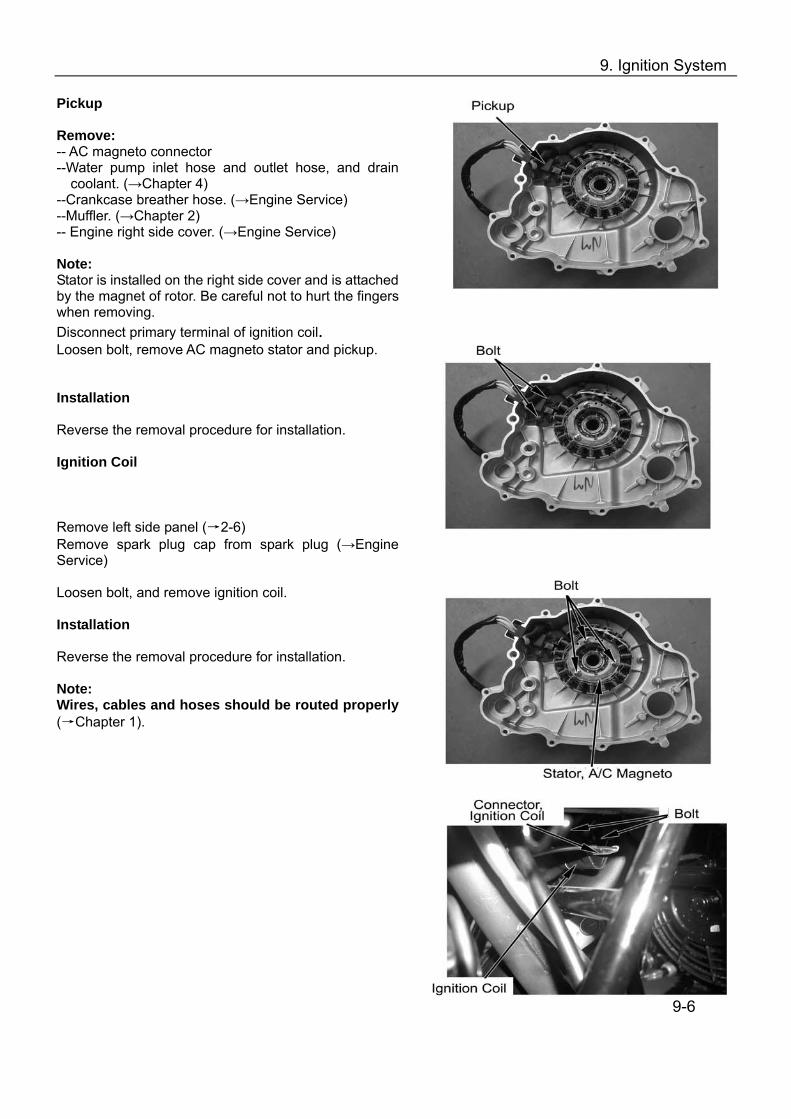
9. Ignition System
Pickup Remove: -- AC magneto connector --Water pump inlet hose and outlet hose, and drain
coolant. (→Chapter 4) --Crankcase breather hose. (→Engine Service) --Muffler. (→Chapter 2) -- Engine right side cover. (→Engine Service) Note: Stator is installed on the right side cover and is attached by the magnet of rotor. Be careful not to hurt the fingers when removing. Disconnect primary terminal of ignition coil. Loosen bolt, remove AC magneto stator and pickup. Installation Reverse the removal procedure for installation. Ignition Coil Remove left side panel (→2-6) Remove spark plug cap from spark plug (→Engine Service) Loosen bolt, and remove ignition coil. Installation Reverse the removal procedure for installation. Note: Wires, cables and hoses should be routed properly (→Chapter 1).
9-6
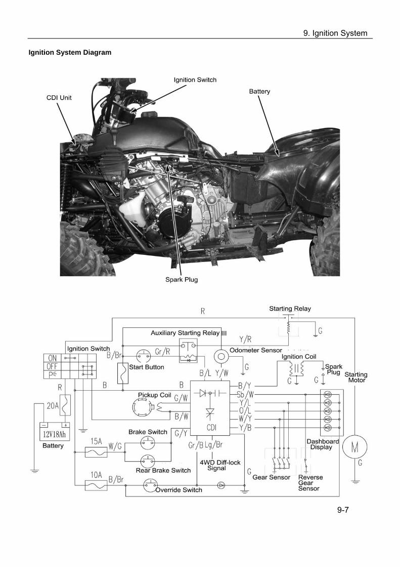
9. Ignition System
Ignition System Diagram
9-7

10. Lighting, Instruments, Switches
Overhaul Info……………….…………..10-1 Troubleshooting ………………….…….10-2 Replacing bulbs.. ………………………10-3 Head Light ……….………….………….10-5
Dashboard ……………………...…….10-9 Fuel Sensor ……………………..……10-10 WaterTemperature Transducer.. …...10-12
Ignition Switch………….…….…………10-6 Handlebar Switch ………………………10-7 Brake Light Switch……………………...10-8 Horn………………………………………10-8 Overhaul Information Warning
Headlight bulb will be very hot when it is turned on. Do not touch it after it is just turned off. Operation should be done when the bulb is cooled down.
Inspection of water temperature alarm may use fire source and liquid of high temperature. Do not put flammable matters nearby and take care not to get burnt.
The temperature of headlight is quite high when turned on. Replacing with bare hand or stained glove will cause oil stains on the glass face which may form hot spot and cause deformation of glass face and damage to bulb.
Pay attention to the following when replacing the bulb. ---Do not replace the bulb when it is turned on. Keep ignition switch in the OFF position, and
replace after the bulb is cooled down. ---Replace the bulb with hands in clean gloves to avoid oil stains on the glass surface. ---Clean the glass with a clean rag dipped in alcohol or isoamyl acetate in case of any oil
stains on the glass surface. If the Inspection has to be done with battery, check if the battery is normal. Inspection of switch continuity can be done without removing the switches from the vehicle. After the inspecting and overhauling of each part, cables and wires should be routed properly
(→chapter 1) Refer to Chapter 2 for removal and installation of taillight and rear turning lights
Overhaul Standard
Item Standard Main 20A Fuse Sub-fuse 10A 15A×3
Headlight (Hi/Lo) 12V-35/35W Brake light / Tail light 12V-21/5W
Turning light 12V-10W×4 Dashboard indicator 12V-1.7W
Light, bulb
Indicators 12V-3.4W
10-1

10. Lighting, Instruments, Switches
Troubleshooting Head Light Cannot Turn On
Broken fuse Open circuit with main cable Burnt Bulb Faulty Switch
10-2
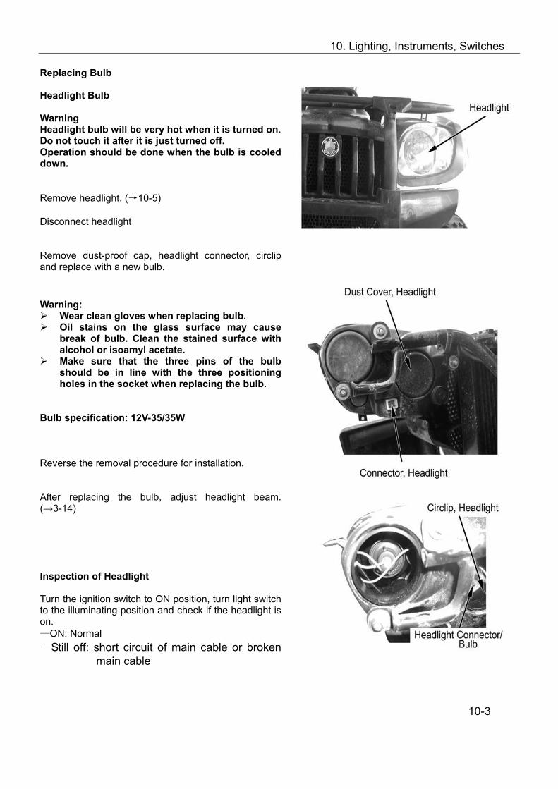
10. Lighting, Instruments, Switches
Replacing Bulb Headlight Bulb Warning Headlight bulb will be very hot when it is turned on. Do not touch it after it is just turned off. Operation should be done when the bulb is cooled down. Remove headlight. (→10-5) Disconnect headlight Remove dust-proof cap, headlight connector, circlip and replace with a new bulb. Warning:
Wear clean gloves when replacing bulb. Oil stains on the glass surface may cause
break of bulb. Clean the stained surface with alcohol or isoamyl acetate.
Make sure that the three pins of the bulb should be in line with the three positioning holes in the socket when replacing the bulb.
Bulb specification: 12V-35/35W Reverse the removal procedure for installation. After replacing the bulb, adjust headlight beam. (→3-14) Inspection of Headlight Turn the ignition switch to ON position, turn light switch to the illuminating position and check if the headlight is on. —ON: Normal —Still off: short circuit of main cable or broken
main cable
10-3
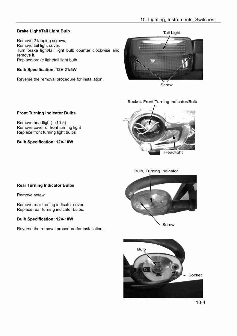
10. Lighting, Instruments, Switches
Brake Light/Tail Light Bulb Remove 2 tapping screws, Remove tail light cover. Turn brake light/tail light bulb counter clockwise and remove it. Replace brake light/tail light bulb Bulb Specification: 12V-21/5W Reverse the removal procedure for installation. Front Turning Indicator Bulbs Remove headlight(→10-5) Remove cover of front turning light Replace front turning light bulbs Bulb Specification: 12V-10W Rear Turning Indicator Bulbs Remove screw Remove rear turning indicator cover. Replace rear turning indicator bulbs. Bulb Specification: 12V-10W Reverse the removal procedure for installation.
10-4

10. Lighting, Instruments, Switches
Dashboard Lighter Bulb Remove dashboard (→10-9) Remove bulb socket and replace with a new bulb. Bulb specification: 12V-1.7W Note: Main cable and wires should be routed properly (→chapter 1) Reverse the removal procedure for installation. Dashboard Indicator Bulb Remove dashboard (→10-9) Remove dashboard indicator socket. Remove indicating light bulb and replace with new one. Bulb specification: 12V-3.4W Reverse the removal procedure for installation. Headlight Remove: --Front fender(→2-8) --3 fixing bolts of headlight cover. --Headlight cover --Fixing bolt of headlight, headlight connector --Headlight.
10-5
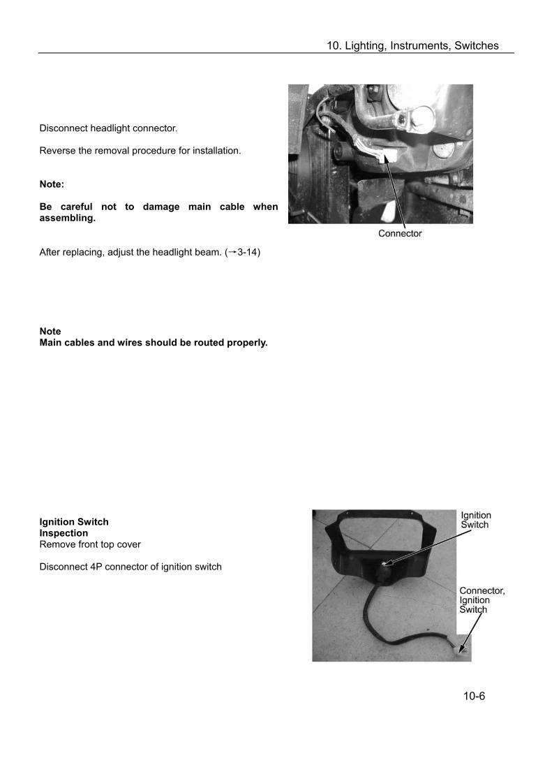
10. Lighting, Instruments, Switches
Disconnect headlight connector. Reverse the removal procedure for installation. Note: Be careful not to damage main cable when assembling. After replacing, adjust the headlight beam. (→3-14) Note Main cables and wires should be routed properly. Ignition Switch Inspection Remove front top cover
Disconnect 4P connector of ignition switch
10-6
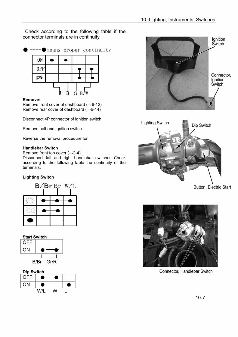
10. Lighting, Instruments, Switches
Check according to the following table if the connector terminals are in continuity. ----means proper continuity
Remove: Remove front cover of dashboard (→6-12) Remove rear cover of dashboard (→6-14) Disconnect 4P connector of ignition switch
Remove bolt and ignition switch
Reverse the removal procedure for Handlebar Switch Remove front top cover (→2-4) Disconnect left and right handlebar switches Check according to the following table the continuity of the terminals. Lighting Switch
Start Switch OFF ON B/Br Gr/R Dip Switch OFF ON W/L W L
10-7
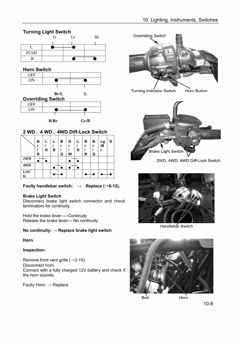
10. Lighting, Instruments, Switches
Turning Light Switch O Gr Sb
L PUSH
R Horn Switch
OFF ON
Br/L L Overriding Switch
OFF ON
B/Br Gr/B 2 WD、4 WD、4WD Diff-Lock Switch
Br /R
L /G
L /B
Br /G
Gr /W
L /G
Br /R
Br /G
Lg/Br
G
2WD
4WD
LOCK
Faulty handlebar switch: → Replace (→6-12). Brake Light Switch Disconnect brake light switch connector and check terminators for continuity. Hold the brake lever-----Continuity Release the brake lever--- No continuity No continuity: → Replace brake light switch Horn Inspection: Remove front vent grille (→2-15) Disconnect horn. Connect with a fully charged 12V battery and check if the horn sounds. Faulty Horn: → Replace
10-8
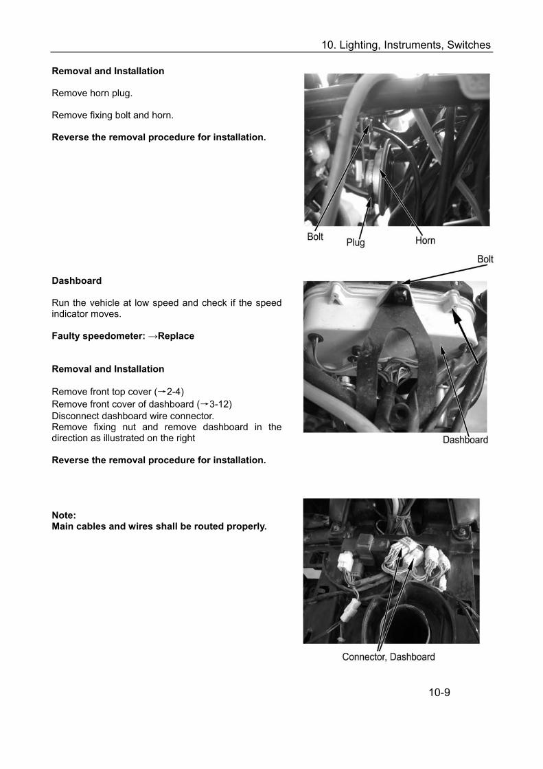
10. Lighting, Instruments, Switches
Removal and Installation Remove horn plug. Remove fixing bolt and horn. Reverse the removal procedure for installation.
Dashboard
Run the vehicle at low speed and check if the speed indicator moves. Faulty speedometer: →Replace Removal and Installation Remove front top cover (→2-4) Remove front cover of dashboard (→3-12) Disconnect dashboard wire connector. Remove fixing nut and remove dashboard in the direction as illustrated on the right Reverse the removal procedure for installation. Note: Main cables and wires shall be routed properly.
10-9
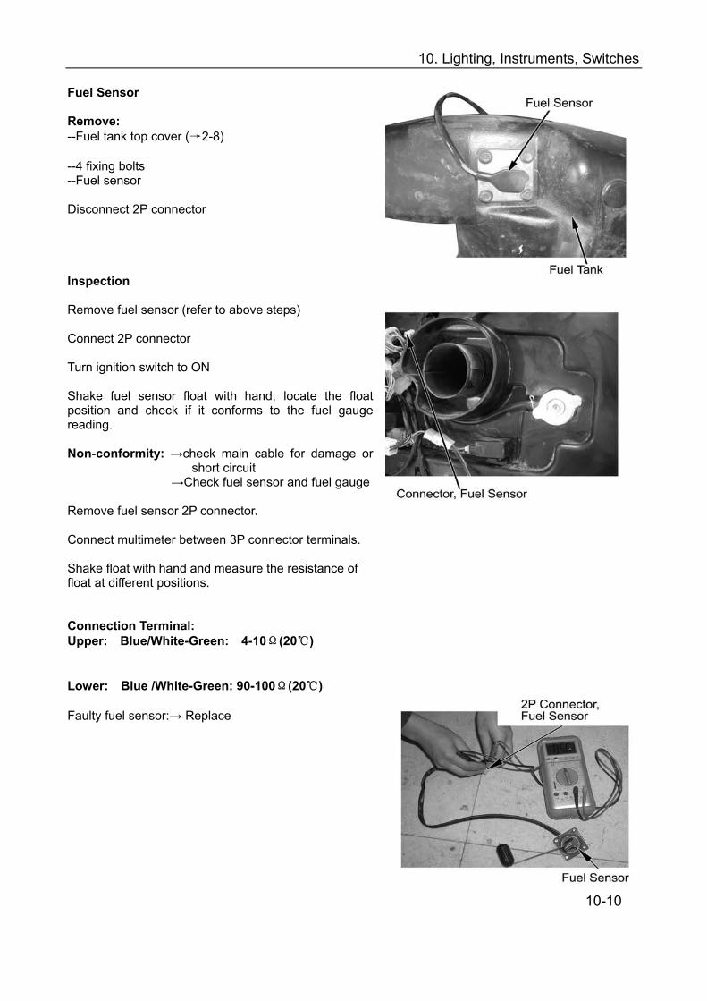
10. Lighting, Instruments, Switches
Fuel Sensor Remove: --Fuel tank top cover (→2-8) --4 fixing bolts --Fuel sensor Disconnect 2P connector Inspection Remove fuel sensor (refer to above steps) Connect 2P connector
Turn ignition switch to ON Shake fuel sensor float with hand, locate the float position and check if it conforms to the fuel gauge reading. Non-conformity: →check main cable for damage or
short circuit →Check fuel sensor and fuel gauge
Remove fuel sensor 2P connector. Connect multimeter between 3P connector terminals. Shake float with hand and measure the resistance of float at different positions. Connection Terminal: Upper: Blue/White-Green: 4-10Ω(20)
Lower: Blue /White-Green: 90-100Ω(20)
Faulty fuel sensor:→ Replace
10-10

10. Lighting, Instruments, Switches
Installation Put fuel sensor into installation hole of fuel tank. Fuel sensor should be fitted properly. No fuel leakage is allowed. Connect 2P connector Inspection of Fuel Gauge Switch on power supply and check if fuel level gauge functions normally. If fuel gauge works normally, Reverse the removal procedure for installation of plastic
parts and seat.
10-11
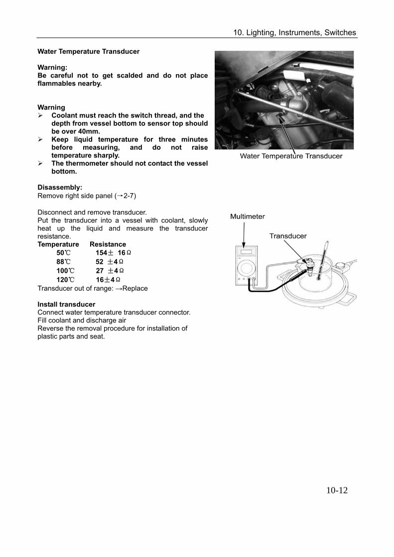
10. Lighting, Instruments, Switches
Water Temperature Transducer Warning: Be careful not to get scalded and do not place flammables nearby.
Warning
Coolant must reach the switch thread, and the depth from vessel bottom to sensor top should be over 40mm.
Keep liquid temperature for three minutes before measuring, and do not raise temperature sharply.
The thermometer should not contact the vessel bottom.
Disassembly: Remove right side panel (→2-7) Disconnect and remove transducer. Put the transducer into a vessel with coolant, slowly heat up the liquid and measure the transducer resistance. Temperature Resistance
50 154± 16Ω 88 52 ±4Ω 100 27 ±4Ω 120 16±4Ω
Transducer out of range: →Replace Install transducer Connect water temperature transducer connector. Fill coolant and discharge air Reverse the removal procedure for installation of plastic parts and seat.
10-12

11. Circuit Diagram, Wiring Diagram
Please reference to PDF document :
LINK: CF500 & CF500A_Circuit Diagram, Wiring Diagram.PDF
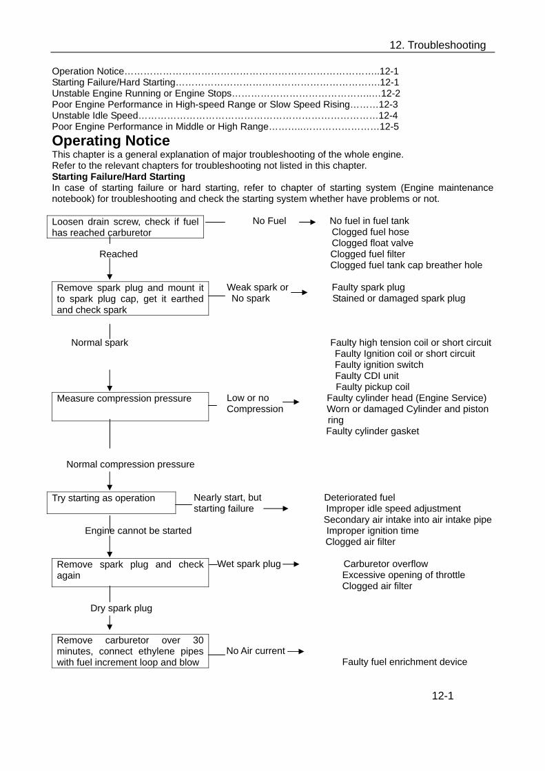
12. Troubleshooting
Operation Notice……………………………………………………………………..12-1 Starting Failure/Hard Starting……………………………………………………….12-1 Unstable Engine Running or Engine Stops……………………………………..…12-2 Poor Engine Performance in High-speed Range or Slow Speed Rising………12-3 Unstable Idle Speed…………………………………………………………………12-4 Poor Engine Performance in Middle or High Range………..……………………12-5 Operating Notice This chapter is a general explanation of major troubleshooting of the whole engine. Refer to the relevant chapters for troubleshooting not listed in this chapter. Starting Failure/Hard Starting In case of starting failure or hard starting, refer to chapter of starting system (Engine maintenance notebook) for troubleshooting and check the starting system whether have problems or not.
No Fuel No fuel in fuel tank Clogged fuel hose Clogged float valve
Reached Clogged fuel filter Clogged fuel tank cap breather hole
Weak spark or Faulty spark plug No spark Stained or damaged spark plug
Normal spark Faulty high tension coil or short circuit
Faulty Ignition coil or short circuit Faulty ignition switch
Faulty CDI unit Faulty pickup coil
Low or no Faulty cylinder head (Engine Service) Compression Worn or damaged Cylinder and piston ring
Faulty cylinder gasket
Normal compression pressure
Nearly start, but Deteriorated fuel starting failure Improper idle speed adjustment
Secondary air intake into air intake pipe Engine cannot be started Improper ignition time Clogged air filter
Wet spark plug Carburetor overflow Excessive opening of throttle Clogged air filter
Dry spark plug
No Air current
Faulty fuel enrichment device
12-1
Loosen drain screw, check if fuel has reached carburetor
Remove spark plug and mount it to spark plug cap, get it earthed and check spark
Measure compression pressure
Try starting as operation
Remove spark plug and check again
Remove carburetor over 30 minutes, connect ethylene pipes with fuel increment loop and blow

12. Troubleshooting
Unstable Engine Running or Engine Stops
No petrol in fuel tank No fuel Clogged fuel hose Clogged float valve
With Fuel Clogged fuel filter Clogged fuel tank cap breather hole
Stained, damaged and color changed
Stained or damaged spark plug Improper spark plug heat value
Normal Spark Plug
Weak spark or Faulty spark plug or stained spark plug No spark Faulty Ignition coil Faulty high tension coil or short circuit
Faulty ignition switch Normal Spark Faulty pickup coil
Faulty CDI unit
Low or no Worn Cylinder and piston ring compression Faulty cylinder gasket pressure
Normal compression pressure
Incorrect Faulty pickup coil Faulty CDI unit
Correct
Improper adjustment Refer to Engine Service
Correct adjustment
Air intake Faulty tightening of carburetor joint
No secondary air
No continuity Broken cable of fuel enrichment device Faulty fuel enrichment device
Normal Continuity 12-2
Loosen drain screw, and check the if fuel has reached carburetor
Remove spark plug and check it
Remove spark plug and mount it to spark plug cap, get it earthed and check spark
Measure compression pressure with pressure meter
Check ignition timing
Check caburetor mixture screw
Check if there is secondary air into carburetor joint
Remove fuel enrichment device wire lead and check continuity

12. Troubleshooting
With Air current Faulty fuel enrichment device No air current
Clogged carburetor
Poor Engine Performance in Hi-speed Range or Slow Speed Rising
No rise of Clogged air filter Engine speed Clogged fuel hose and filter
Clogged fuel tank cap breather hole Clogged muffler
Engine speed rises
Incorrect Faulty pickup coil
Faulty CDI unit
Correct
Low or no Worn Cylinder and piston ring Compression Pressure Faulty cylinder gasket
Normal compression pressure
Clogged Clogged carburetor
Not clogged
Stained damage and color changed
Spark plug stained and damaged Improper spark plug heat value
Normal Spark Plug
Overheated Faulty mixture gas Faulty fuel Carbon deposit in combustion Chamber
Too much advanced ignition timing Overheated
Cylinder knock Carbon deposit in combustion chamber
No cylinder knock Clutch slip 12-3
Connect fuel enrichment device wire lead with battery for 5 Minutes. Connect ethylene pipe with fuel increment loop and blow.
Run vehicle at high engine speed (on an flat asphalt road)
Check ignition timing
Measure compression pressure with pressure meter
Check carburetor
Check spark plug
Check the engine for overheating
Accelerate or continuous high-speed operation
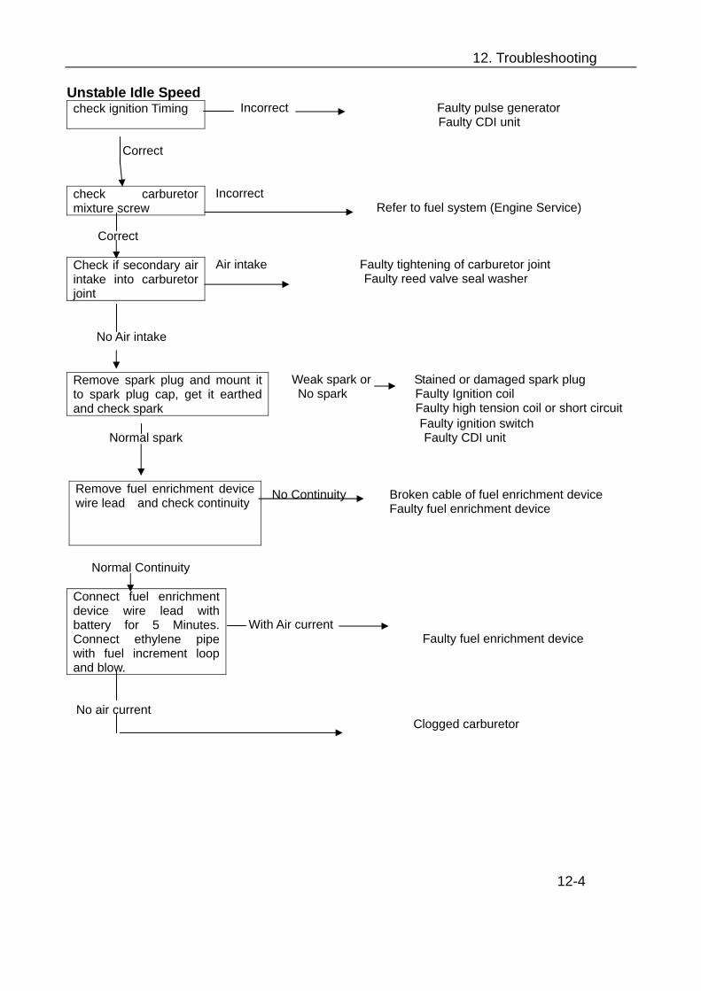
12. Troubleshooting
Unstable Idle Speed Incorrect Faulty pulse generator Faulty CDI unit
Correct
Incorrect Refer to fuel system (Engine Service)
Correct
Air intake Faulty tightening of carburetor joint
Faulty reed valve seal washer
No Air intake
Weak spark or Stained or damaged spark plug No spark Faulty Ignition coil Faulty high tension coil or short circuit
Faulty ignition switch Normal spark Faulty CDI unit
No Continuity Broken cable of fuel enrichment device Faulty fuel enrichment device
Normal Continuity
With Air current
Faulty fuel enrichment device
No air current
Clogged carburetor
12-4
check ignition Timing
check carburetor mixture screw
Check if secondary air intake into carburetor joint
Remove spark plug and mount it to spark plug cap, get it earthed and check spark
Remove fuel enrichment device wire lead and check continuity
Connect fuel enrichment device wire lead with battery for 5 Minutes. Connect ethylene pipe with fuel increment loop and blow.
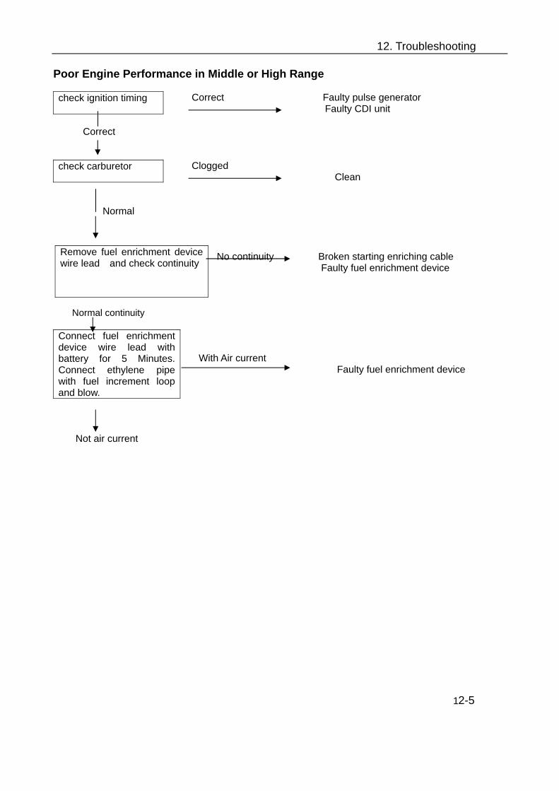
12. Troubleshooting
Poor Engine Performance in Middle or High Range
Correct Faulty pulse generator Faulty CDI unit
Correct
Clogged Clean
Normal
No continuity Broken starting enriching cable
Faulty fuel enrichment device
Normal continuity
With Air current Faulty fuel enrichment device
Not air current
12-5
check ignition timing
check carburetor
Remove fuel enrichment device wire lead and check continuity
Connect fuel enrichment device wire lead with battery for 5 Minutes. Connect ethylene pipe with fuel increment loop and blow.

13.Engine Overhaul Information
Conversion Table Item Conversion Press 1kgf/cm2 =98.0665KPa 1KPa=1000Pa
1mmHg=133.322Pa=0.133322KPa Torque 1kgf.m=9.08665N.m Volume 1ml=1cm3=1cc
1l=1000 cm3 Force 1kgf=9.80665N Warning/Caution/Note Please read this manual and follow is instructions carefully. To emphasize special information, the symbol and the words WARNING,CAUTION and NOTE have special meanings. Pay attention to the messages highlighted by these signal words. Warning: Indicates a potential hazard that could result in injury or death. Caution: indicates a potential hazard that could be result in vehicle damage. Note: provides key information to make procedures easier or instruction clearer. Please note, however, that the warnings and cautions contained in this manual can’t possibly cover all the potential dangerous information to the servicing, or lack of the vehicle. Except WARNINGS and CAUTIONS stated in this manual, mechanic should have a basic understanding of the mechanical ideas and the procedure of machine repair. If mechanic can’t master all the troubleshooting operation, please consult with qualified mechanic for advice.

13.Engine Overhaul Information
General Precautions ………………………………..…………………………..10-2
Fuel, Oil and Coolant……………………………………………………………10-3
Brake-in …………………………………………………………………………..10-3
Engine Exterior and Engine No…………………………………………………10-4
Engine Specification………………………………………………..……………10-5
Overhaul Data…………………………………………………………………….10-6
Tightening Torque Table…………………………………………………………..10-10
Tools………………………………………………………………………………..10-12
Materials for Operation and Fixing ……………….……………………….…….10-14 . . 13-1
13.Engine Overhaul Information
GENERAL PRECAUTIONS
When two or more persons work together, keep reminding each other for safety purpose. When start the engine indoors, make sure that the exhaust gas is forced outdoors. If use hazardous or flammable material, please strictly operate according to manufacturer’s operation
manual. Operate in a well- ventilated place. Never use gasoline as a cleaning solvent. Do not touch the engine oil, radiator or muffler with bare hands to avoid scalding before it is cooled. Check all the lines, and fittings related to the system for leakages, after repairing fuel, cooling, lubricating
or exhaust system . Do not dispose used oil, coolant or defective parts optionally for environmental purpose.
CAUTION:
Use genuine CFMOTO parts or their equivalent. Place and store the disassembled parts separately in order for correct assemble. Use special tools according to service manual. Make sure that all parts used in reassembly are clean, lubricated them when specified. Use the special lubricants, sealants and greases. Pre-tighten the bolts, nuts and screws, then tighten according to the specified torque, from big to small and
from inner side to outer side. Fix torque screw with torque wrench, clean grease or oil from the screw thread before fixing. Check the parts after disassembling, clean the parts before measuring. Check parts for tightness and proper operation, after assembling. Replace the disassembled washers, o-rings, seals, locknuts, lockwashers, cotter pins, circlips with new
ones. 13-2
Warning ! Proper service and repair procedures are important for the safety of operator and the safety and reliability of the vehicle.

13.Engine Overhaul Information
FUEL, OIL, COOLANT Fuel Use unleaded gasoline with octane number over 90.
OIL Use a premium quality 4-stroke motor oil to ensure longer service life of your vehicle. Use only oils that meet API service classifications SF or SG and that have a viscosity rating of SAE10W/40. If oil with a rating of SAE 10W/40 is not available, select an alternative according to the chart. ENGINE COOLANT Since antifreeze also has corrosion and rust-inhibiting properties, always use coolant containing antifreeze, even if the atmospheric temperature does not go below the freezing point. It is suggested that the freezing point of antifreeze should be 5 lower than the lowest ambient temperature where the vehicle is used. Recommended Coolant: -35 antifreeze, corrosion-resistant, high boiling point coolant Warning! Coolant is poisonous. Never drink it. Store it properly. Caution: DO NOT mix coolant with that of other engines. BREAK-IN PROCEDURES During manufacturing only the best possible material are used and all machined parts are finished to a very high standard. It is still necessary to allow the moving parts to “BREAK-IN” before subjecting the engine to maximum stresses. The future performance and reliability of the engine depends on the care and restraint exercised during its early life. Refer to the following break-in engine speed recommendations. For better performance and durability, a new engine requires a run-in time of 20 hours as under: 0~10 Hours: Avoid continuous operation above half throttle. Allow a cooling off period of five to ten minutes after every hour of operation. Vary the speed of vehicle from time to time. Do not operate it at one set throttle position. 10~20 Hours Avoid prolonged operation above 3/4 throttles. Rev the vehicle freely but do not use full throttle at any time. Note: Keep the daily maintenance during the run-in time and eliminate the troubles, if any. After 20h run-in time, do the maintenance according to the owner’s manual for normal operation of the ATV.
13-3
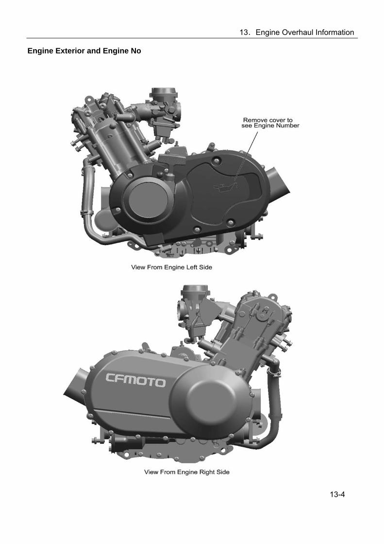
13.Engine Overhaul Information
Engine Exterior and Engine No
13-4

13.Engine Overhaul Information
Engine Specification REF.NO
ITEM Type/SPECIFICATION
1 Type Single Cylinder, 4-Storke, Liquid-cooled, 4 Valve, SOHC
2 Bore and stroke 87.5mm×82.0mm 3 Displacement 493ml 4 Compression ratio 10.2: 1
5 Lowest continuous idle speed with load 1300r/min±100r/min
6 Starting type Electrical starting/ Recoil Starting
Ignition / Ignition Timing
CDI Magneto ignition/BTDC10°1500r/min
Spark Plug/ Spark Plug Gap
DPR7EA-9 (NGK)/0.8mm-0.9mm 7 Electrical System
Magneto Permanent Magnet AC Type
Combustion Chamber Triangle Combustion Chamber
Carburetion Type/Model Vacuum Diaphragm Type/MIKUNI BSR36-89
Air Filter Sponge Element Filter 8
Combustion System
Gasoline RQ-90
9 Valve System Valve Type SOHC/Chain Drive
Lubrication Type Pressure & Splash Oil Pump Rotor Type Filter Type Full Flow Filter Screen 10 Lubrication
System Oil Type SAE10W-40/SF
Cooling Type Closed Coolant Circulation 11 Cooling
System Coolant Type —35 Rust-resistant antifreeze
Clutch type Wet, Auto-centrifugal Operation Mode Automatic(CVT)+Parking and Gear Shifting
Gears 2 Forward Gears + 1 Reverse Gear Shift Type/Sequence Hand Operation/L-H-N-R-P
(CVT) Gear Ratio 2.88-0.70 Final Ratio 1.333(24/18, bevel gear)
Secondary Ratio
1.952(41/21)
Gears Low Gear:2.25(36/16) High Gear :1.35(27/20) Reverse Gear:1.471(25/17)
12 Drive System
Transfer Gear Ratio
Total Low Gear:5.857, High Gear:3.514,Reverse Gear:3.82813 Overall Dimension 610×568×519mm 14 Net Weight 70kg 15 Output type Front and rear shaft output 16 Rotational Direction of Engine Output Clockwise (from behind engine at forward gear)
13-5

13.Engine Overhaul Information
Overhaul Data
Item Standard Service Limit Remark IN 30.6 Valve Head Diameter EX 27.0
-----------
IN 0.05-0.10 Valve Clearance
EX 0.010-0.037 ------------
IN 0.010-0.037 Clearance Between Valve Guide and Valve Stem EX 0.030-0.057
------------
Inner Diameter of Valve Guide
IN & EX 5.000-5.012 -------------
IN 4.975-4.990 ------------- Outer Diameter of Valve Stem
EX 4.955-4.970 ------------- Valve Stem Play IN & EX ------------- 0.05 Length of Valve Stem End IN & EX 2.9-3.1 2.3 Valve Head Thickness IN & EX ------------- 0.5 Play of Valve Head Seal IN & EX ------------ 0.03 Width of Valve Seat Seal IN & EX 0.9-1.1 ------------- Valve Spring Free Length IN & EX 40 38.8
Valve Spring Tension IN & EX 182-210N,(when compressed to 31.5mm)
--------------
IN 33.430-33.490 33.130 Cam Height
EX 33.500-33.560 33.200 Φ22 0.032-0.066 0.150 Clearance Between
Camshaft Outer Diameter & Hole
Φ17.5 0.028-0.059 0.150
Φ22 21.959-21.980 --------------- Camshaft Outer Diameter
Φ17.5 17.466-17.484 --------------- Φ22 22.012-22.025 ---------------- Inner Diameter of Camshaft
Hole Φ17.5 17.512-17.525 ---------------- Camshaft Play 0.10 Inner Diameter of Rocker Arm IN & EX 12.000-12.018 ---------------- Outer Diameter of Rocker Arm
IN & EX 11.973-11.984 ----------------
Cylinder Head Distortion 0.03 0.05 Cylinder Head Cover Distortion
0.03 0.05
13-6

13.Engine Overhaul Information
Cylinder + Piston + Piston Ring + Connecting Rod Item Standard Service Limit Remark
Cylinder Pressure 1000KPa ------------ Cylinder-Piston Clearance 0.030-0.051 0.15 Piston Skirt Diameter 87.460-87.480
(10mm form skirt end) 87.380
Inner Diameter of Cylinder 87.500-87.522 ------------ Cylinder Joint Face Distortion 0.015 0.05
Top Ring
R About 11.7 8.9
Piston Ring Free Gap 2ND Ring
R About 12 9.5
Top Ring 0.15-0.30 0.60 Piston Ring Gap In Bore 2ND Ring 0.15-0.30 0.60 Top Ring 0.04-0.08 0.180 Piston Ring Groove
Clearance 2ND Ring 0.03-0.07 0.150 Top Ring 0.97-0.99 -------------
Piston Ring Thickness 2ND Ring 1.17-1.19 ------------- Top Ring 1.03-1.05 ------------- 2ND Ring 1.22-1.24 ------------- Piston Ring Groove Width Oil Ring 2.51-2.53
Inner Diameter of Piston Pin Hole
23.002-23.008 23.030
Outer Diameter of Piston Pin 22.995-23.000 22.980 Inner Diameter of Connecting Rod Small End
23.006-23.014 23.040
Clearance of Connecting Rod Big End
0.10-0.55 1.0
Thickness of Connecting Rod Big End
24.95-25.00
Crankshaft Play 0.03 0.08 Lubrication
Item Standard Service Limit Remark Clearance between Inner and Outer Rotors
0.03mm-0.10mm 0.15mm
Clearance between Outer Rotor and Oil Pump Body
0.03mm-0.10mm 0.12mm
Oil Pressure 130Kpa-170Kpa ( 3000r/min) --------- Oil Type SAE10W-40, API SF or SG ---------
When changing 1900ml ---------- When Replacing Filter
2000ml ---------- Oil Capacity
Engine Repair 2200ml --------- 13-7
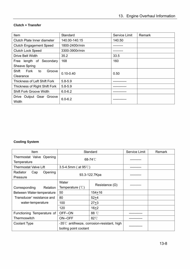
13.Engine Overhaul Information
Clutch + Transfer Item Standard Service Limit Remark Clutch Plate Inner diameter 140.00-140.15 140.50 Clutch Engagement Speed 1800-2400r/min --------- Clutch Lock Speed 3300-3900r/min --------- Drive Belt Width 35.2 33.5 Free length of Secondary Sheave Spring
168 160
Shift Fork to Groove Clearance
0.10-0.40 0.50
Thickness of Left Shift Fork 5.8-5.9 ------------ Thickness of Right Shift Fork 5.8-5.9 ------------ Shift Fork Groove Width 6.0-6.2 ------------ Drive Output Gear Groove Width
6.0-6.2 ------------
Cooling System
Item Standard Service Limit Remark Thermostat Valve Opening Temperature
68-74 ----------
Thermostat Valve Lift 3.5-4.5mm ( at 95) ---------- Radiator Cap Opening Pressure
93.3-122.7Kpa ----------
Water Temperature ()
Resistance (Ω) ----------
50 154+16 80 52+4 100 27+3
Corresponding Relation Between Water-temperature Transducer’ resistance and
water-temperature 120 16+2 OFF--ON 88 ------------ Functioning Temperature of
Thermoswitch ON--OFF 82 ------------ Coolant Type -35 antifreeze, corrosion-resistant, high
boiling point coolant ------------
13-8
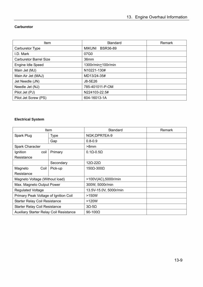
13.Engine Overhaul Information
Carburetor
Item Standard Remark Carburetor Type MIKUNI BSR36-89 I.D. Mark 07G0 Carburetor Barrel Size 36mm Engine Idle Speed 1300r/min+100r/min Main Jet (MJ) N10221-130# Main Air Jet (MAJ) MD13/24-35# Jet Needle (JN) J8-5E26 Needle Jet (NJ) 785-401011-P-OM Pilot Jet (PJ) N224103-22.5# Pilot Jet Screw (PS) 604-16013-1A Electrical System
Item Standard Remark Type NGK;DPR7EA-9 Spark Plug Gap 0.8-0.9
Spark Character >8mm Ignition coil Resistance
Primary 0.1Ω-0.5Ω
Secondary 12Ω-22Ω Magneto Coil Resistance
Pick-up 150Ω-300Ω
Magneto Voltage (Without load) >100V(AC),5000r/min Max. Magneto Output Power 300W, 5000r/min Regulated Voltage 13.5V-15.0V, 5000r/min Primary Peak Voltage of Ignition Coil >150W Starter Relay Coil Resistance >120W Starter Relay Coil Resistance 3Ω-5Ω Auxiliary Starter Relay Coil Resistance 90-100Ω
13-9
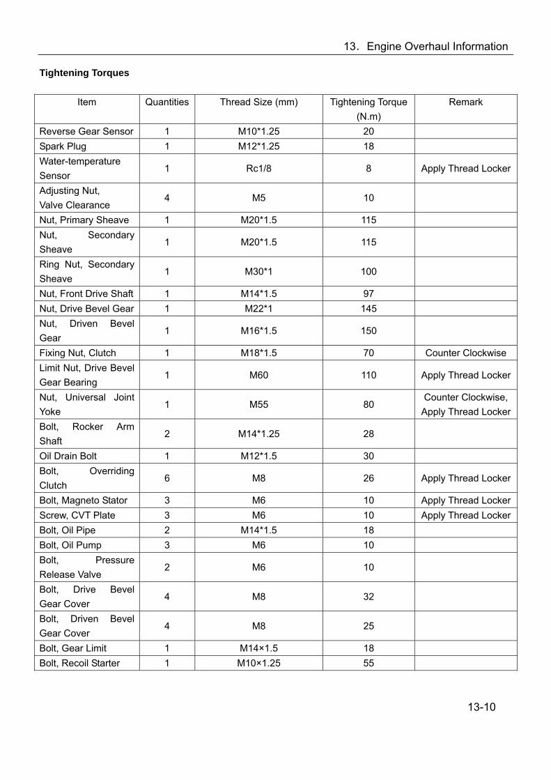
13.Engine Overhaul Information
Tightening Torques
Item Quantities Thread Size (mm) Tightening Torque (N.m)
Remark
Reverse Gear Sensor 1 M10*1.25 20 Spark Plug 1 M12*1.25 18 Water-temperature Sensor
1 Rc1/8 8 Apply Thread Locker
Adjusting Nut, Valve Clearance
4 M5 10
Nut, Primary Sheave 1 M20*1.5 115 Nut, Secondary Sheave
1 M20*1.5 115
Ring Nut, Secondary Sheave
1 M30*1 100
Nut, Front Drive Shaft 1 M14*1.5 97 Nut, Drive Bevel Gear 1 M22*1 145 Nut, Driven Bevel Gear
1 M16*1.5 150
Fixing Nut, Clutch 1 M18*1.5 70 Counter Clockwise Limit Nut, Drive Bevel Gear Bearing
1 M60 110 Apply Thread Locker
Nut, Universal Joint Yoke
1 M55 80 Counter Clockwise,
Apply Thread LockerBolt, Rocker Arm Shaft
2 M14*1.25 28
Oil Drain Bolt 1 M12*1.5 30 Bolt, Overriding Clutch
6 M8 26 Apply Thread Locker
Bolt, Magneto Stator 3 M6 10 Apply Thread LockerScrew, CVT Plate 3 M6 10 Apply Thread LockerBolt, Oil Pipe 2 M14*1.5 18 Bolt, Oil Pump 3 M6 10 Bolt, Pressure Release Valve
2 M6 10
Bolt, Drive Bevel Gear Cover
4 M8 32
Bolt, Driven Bevel Gear Cover
4 M8 25
Bolt, Gear Limit 1 M14×1.5 18 Bolt, Recoil Starter 1 M10×1.25 55
13-10
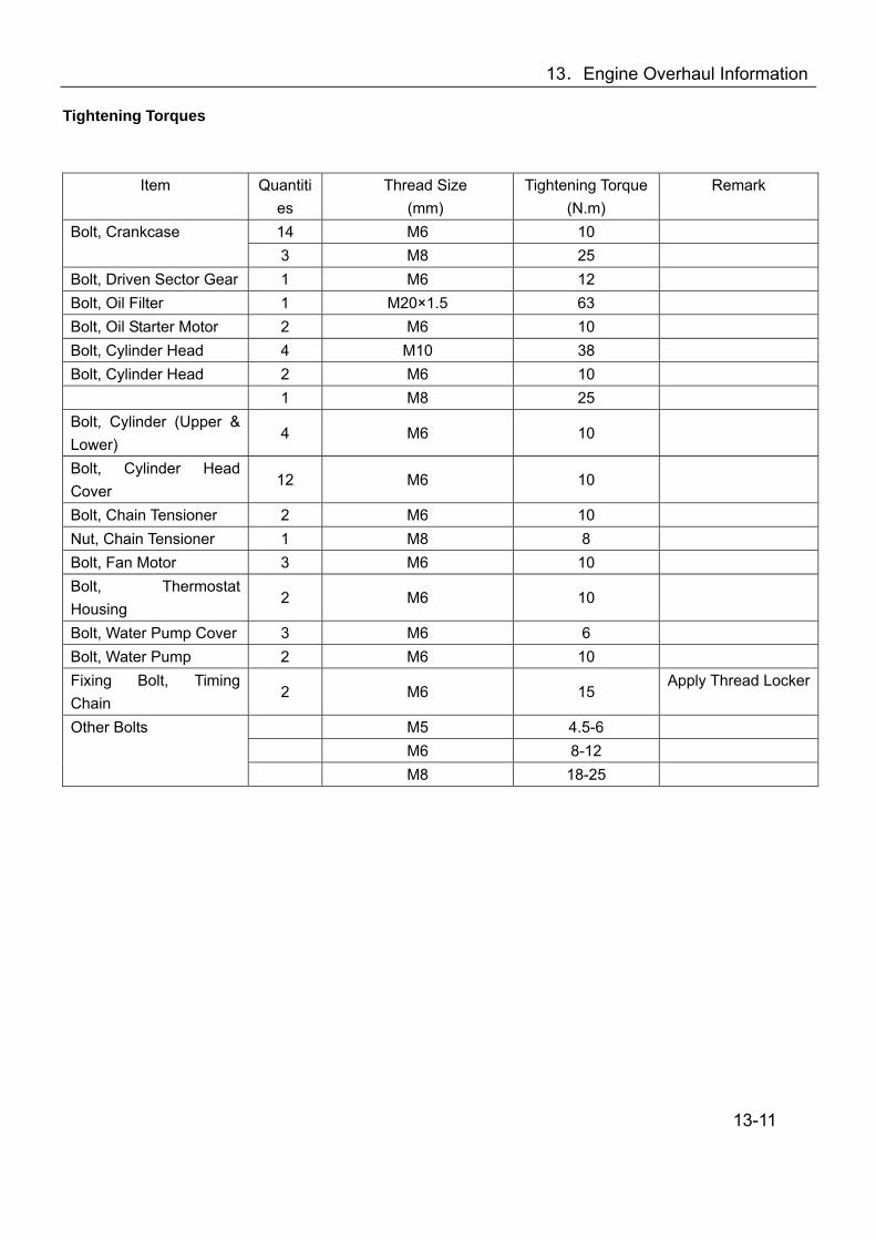
13.Engine Overhaul Information
Tightening Torques
Item Quantities
Thread Size (mm)
Tightening Torque (N.m)
Remark
14 M6 10 Bolt, Crankcase 3 M8 25
Bolt, Driven Sector Gear 1 M6 12 Bolt, Oil Filter 1 M20×1.5 63 Bolt, Oil Starter Motor 2 M6 10 Bolt, Cylinder Head 4 M10 38 Bolt, Cylinder Head 2 M6 10 1 M8 25 Bolt, Cylinder (Upper & Lower)
4 M6 10
Bolt, Cylinder Head Cover
12 M6 10
Bolt, Chain Tensioner 2 M6 10 Nut, Chain Tensioner 1 M8 8 Bolt, Fan Motor 3 M6 10 Bolt, Thermostat Housing
2 M6 10
Bolt, Water Pump Cover 3 M6 6 Bolt, Water Pump 2 M6 10 Fixing Bolt, Timing Chain
2 M6 15 Apply Thread Locker
M5 4.5-6 M6 8-12
Other Bolts
M8 18-25 13-11

13.Engine Overhaul Information
Maintenance Tools Measurement Tools No. Description Specification Purpose 1 Vernier Caliper 0-150mm For measuring the length and thickness 2 Micrometer 0-25mm For measuring outer diameters of rocker arm, valve stem
and camshaft 3 Micrometer 25-50mm For measuring the max. lift of camshaft 4 Micrometer 75-100mm For measuring piston skirt 5 Cylinder Gauge For measuring cylinder bore diameter 6 Small Bore Gauge 10-34mm Fore measuring inner gauge of rocker arm, piston pin bore,
connecting rod small end bore 7 Dial Indicator 1/100 For measuring the play 8 Straightedge Gauge Plane measuring 9 Feeler Gauge Plane and valve clearance measuring 10 Fuel Level Gauge For measuring the carburetor fuel level 11 Thickness Gauge For measuring the clearance 12 Spring Balance For measuring the spring tension 13 Tachometer For measuring engine speed 14 Oil Pressure Gauge For measuring oil pressure 15 Compression Gauge &
Adapter For measuring cylinder compression
16 Radiator Cap Tester For measuring radiator cap opening pressure 17 Ohmmeter For measuring resistance and voltage 18 Ammeter For measuring current/switches 19 Thermometer For measuring liquid temperature 20 Timing Light For checking the ignition timing 21 Torque Wrench For measuring the tightening torque General-purpose and Auxiliary Tools 22 Alcohol Burner Heating up 23 Magnetic Stand For micrometer 24 Slab Auxiliary tool for measuring 25 V-block For measuring the play 26 Tweezer For installation of valve cotter 27 Circlip Pliers For removal and installation of circlips 28 Long Nose Pliers For removal and installation of retainers 29 Impact Driver For removal of cross-headed bolts 30 (-) Driver 31 (+) Driver 13-12

13.Engine Overhaul Information
Special Tools No. Description Specifications Purpose 1 Spark Plug Wrench Removal and installation of spark plug 2 Clutch Holder For removing/installing clutch carrier nuts 3 Oil Filter Wrench Removal and installation of oil filter cartridge 4 Piston Pin Puller For removal of piston pin 5 Flywheel Puller For removal of magneto rotor 6 Crankcase Separating Tool For separation of left and right crankcase 7 Crankshaft Remover For removal of crankshaft from left crankcase 8 Crankshaft Installation Set For installing crankshaft to left crankshaft 9 Valve Spring Compressor For removal and installation of valve spring 10 Valve Seat Cutter For valve-seating 11 Ring Nut Wrench Removal/installation of CVT secondary sheave 12 Sheave Holder Removal/installation of CVT secondary sheave 13 Sheave Spring Compressor Removal/installation of CVT secondary sheave 14 Couple Gear/Middle Shaft
Tool
Removal/installation of the coupling gear nut
15 Bearing Driver Set For installation of bearing and oil seal 16 Bearing Removing Tool Set For removal of bearing 17 Oil Seal Removing Tool For removal of oil seal 18 Universal Joint Holder For removal/installation of the universal joint yoke nut
13-13

13.Engine Overhaul Information
Materials for Operation and Fixing Materials for engine operation engine oil, grease and coolant. Fixing materials include sealant, thread locker, etc.
13-14
Description Type Application Area Remark
Lubricating Oil/Engine Oil
SAE10W-30 or SAE10W-40 or SAE20W-50 API service classifications SF or SG
Cylinder bore Crankcase Refer to Engine Lubrication System (→14-14)
capacity 1900ml (for changing oil) 2000ml (for replacing filet) 2200ml (for engine repairing)
Molybdenum lubrication oil
piston pin、valve stem、valve oil seal、camshaft
Lubricating Grease #3 MoS2 Lithium Base Grease
Oil seal lip, O-ring and sealing faces of other rubber seal materials, bearings with seals, CVT bearing and collar
Coolant -35 antifreeze, corrosion-resistant, high boiling point coolant
Cooling system、Water-seal Capacity according to radiator and water hose system
Joint Face Sealant Joint face of crankcase, crankcase and cylinder, cylinder head and cover
Thread Locker Thread Parts See 10-10, 10-11
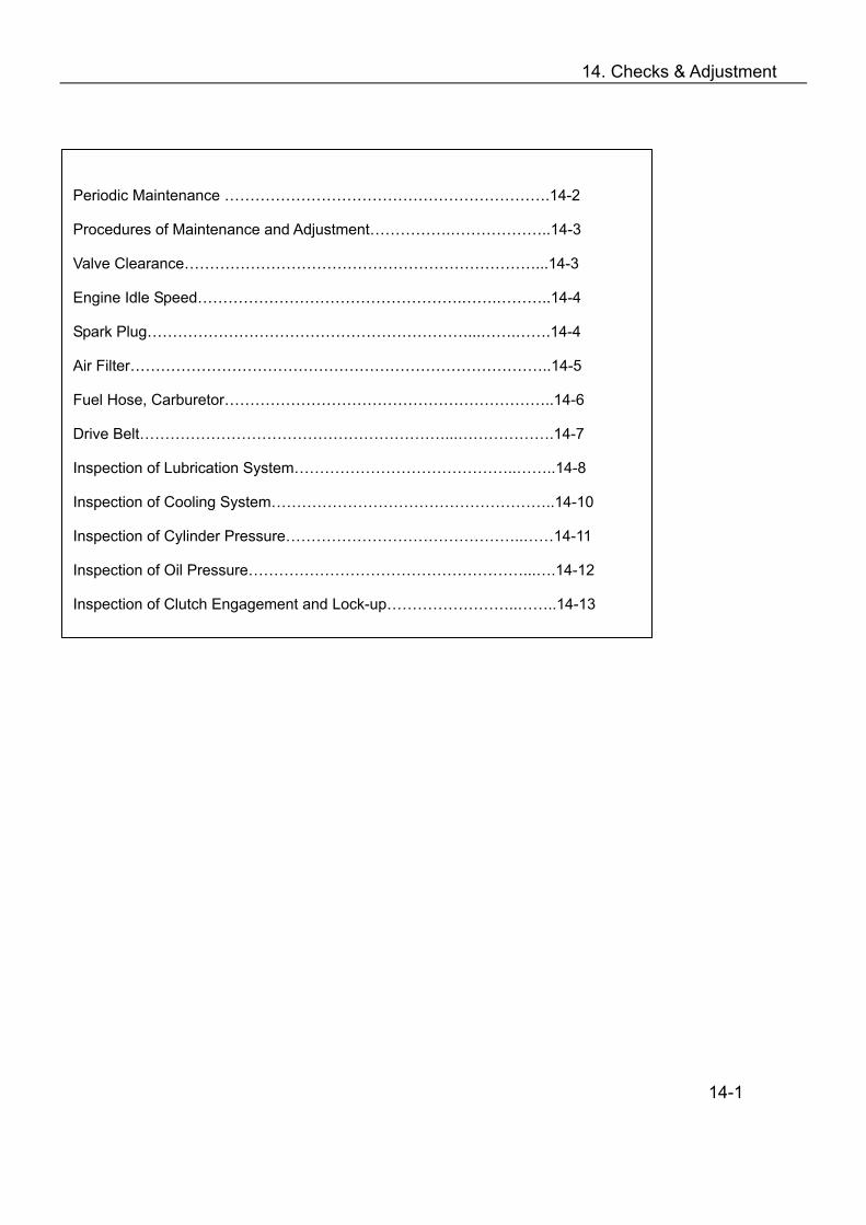
14. Checks & Adjustment
14-1
Periodic Maintenance ……………………………………………………….14-2
Procedures of Maintenance and Adjustment…………….………………..14-3
Valve Clearance……………………………………………………………...14-3
Engine Idle Speed…………………………………………….…….………..14-4
Spark Plug………………………………………………………...…….…….14-4
Air Filter………………………………………………………………………..14-5
Fuel Hose, Carburetor………………………………………………………..14-6
Drive Belt……………………………………………………...……………….14-7
Inspection of Lubrication System……………………………………..……..14-8
Inspection of Cooling System………………………………………………..14-10
Inspection of Cylinder Pressure………………………………………..……14-11
Inspection of Oil Pressure………………………………………………...….14-12
Inspection of Clutch Engagement and Lock-up……………………..……..14-13

14. Checks & Adjustment
Periodic Maintenance Table
The table below lists the recommended intervals for all the required periodic maintenance work necessary to
keep the vehicle at its best performance and economy. Maintenance intervals are expressed in terms of
kilometer, miles and hours, whichever occurs first.
Note: More frequent maintenance may be required on vehicles that are used in severe conditions.
Km Initial 200 Every 1000 Every 2000 Miles Initial 100 Every 600 Every 1200
Interval
Item Hours Initial 20 Every 40 Every 80
Remark
Valve Clearance I -- I
IN: 0.05~0.10 EX:0.17~0.22
Idle Speed I I I 1300±100r/Min -- -- I Spark Plug
Replace every 6000Km No carbon deposit Gap: 0.8~0.9mm
Air Filter -- C C Replace every 2000Km Fuel Hose, Carburetor -- -- I Replace every 4 years Clutch -- -- I Drive Belt -- I R Engine Oil R -- R Oil Filter R -- R Coolant Level I I I Water Hose & Pipes I I I Coolant Replace every 2 years I=Inpection and adjust, or replace if necessary R=Replace C=Clean
14-2
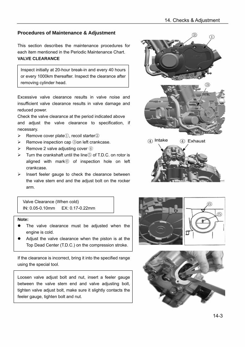
14. Checks & Adjustment
Procedures of Maintenance & Adjustment This section describes the maintenance procedures for each item mentioned in the Periodic Maintenance Chart. VALVE CLEARANCE Excessive valve clearance results in valve noise and insufficient valve clearance results in valve damage and reduced power. Check the valve clearance at the period indicated above and adjust the valve clearance to specification, if necessary.
Remove cover plate , recoil starter① ② Remove inspection cap ③on left crankcase. Remove 2 valve adjusting cover ④ Turn the crankshaft until the line⑤ of T.D.C. on rotor is
aligned with mark⑥ of inspection hole on left crankcase.
Insert feeler gauge to check the clearance between the valve stem end and the adjust bolt on the rocker arm.
Note: The valve clearance must be adjusted when the
engine is cold. Adjust the valve clearance when the piston is at the
Top Dead Center (T.D.C.) on the compression stroke. If the clearance is incorrect, bring it into the specified range using the special tool. Loosen valve adjust bolt and nut, insert a feeler gauge between the valve stem end and valve adjusting bolt, tighten valve adjust bolt, make sure it slightly contacts the feeler gauge, tighten bolt and nut.
14-3
Inspect initially at 20-hour break-in and every 40 hours or every 1000km thereafter. Inspect the clearance after removing cylinder head.
Valve Clearance (When cold) IN: 0.05-0.10mm EX: 0.17-0.22mm

14. Checks & Adjustment
Take out the feeler gauge, measure the clearance. If the clearance is incorrect, repeat the above steps until the proper clearance is obtained. Locknut: 10 N.m Install: 2 valve adjusting cover; Inspection cap; Recoil starter; Cover plate; Apply a small quantity of THREAD LOCKER to recoil starter fixing bolts. Tools: Valve adjuster Feeler gauge Material: Thread Locker ENGINE IDLE SPEED Start the engine and warm it up for several minutes, measure engine speed with a tachometer. Set the engine idle speed between 1200~1400 r/min by turning the throttle stop screw of carburetor. Engine idle speed: 1300r/min±100r/min Note: Make this adjustment when the engine is hot Tool: Tachometer SPARK PLUG Inspect initially at 20 hours run-in and every 80 hours or 2000km thereafter. Replace every 6000km. Remove the spark plug with a special tool Specification: DER7EA-9(NGK) If the electrode is extremely worn or burnt, or spark plug has a broken insulator, damaged thread, etc, replace the spark plug with a new one.
14-4
Caution: Securely tighten the locknut after completing adjustment
Inspect initially at 20 hours run-in and every 40 hours or 1000km thereafter.

14. Checks & Adjustment
In case of carbon deposit, clean with a proper tool. SPARK PLUG GAP Measure the spark plug gap with a feeler gauge. Out of specification: → Adjust Spark plug gap: 0.8-0.9mm Installation: Tightening Torque: 18 N.m Tool: Spark Plug Wrench, Feeler Gauge Air Filter If the air cleaner is clogged with dust, intake resistance will be increased, with a resultant decrease in power output and an increase in fuel consumption. Check and clean the air filter as following: Remove fixing clamp① and top cover② Note: Be careful not to drop the o-ring into the air filter box that is attached to the air filter top cover. Loosen screw③, remove filter element④, separate support⑤, filter element⑥ and filter element seat⑦.
Fill a wash pan of a proper size with a non-flammable cleaning solvent A. Immerse the filter element in cleaning solvent and wash it.
Press the filter element between the palms of both hands to remove the excess solvent. Do not twist or wring the element or it will tear.
Immerse the element in engine oil B, and then squeeze out the excess oil leaving the element slightly wet.
14-5
Caution: Check the thread size and reach when replacing the spark plug. If the reach is too short, carbon will be deposited on the screw portion of the spark plug hole and engine damage may result.
Caution: To avoid damaging the cylinder head threads; first, tighten the spark plug with fingers, and then tighten it to the specified torque using the spark plug wrench.
Inspect every 40 hours or 1000 km, clean it ifnecessary.
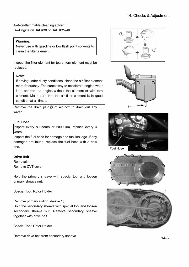
14. Checks & Adjustment
A--Non-flammable cleaning solvent B—Engine oil SAE#30 or SAE10W/40.
Inspect the filter element for tears. torn element must be replaced. Remove the drain plug⑧ of air box to drain out any water. Fuel Hose Inspect every 80 hours or 2000 km, replace every 4 years. Inspect the fuel hose for damage and fuel leakage. If any damages are found, replace the fuel hose with a new one. Drive Belt Removal: Remove CVT cover Hold the primary sheave with special tool and loosen primary sheave nut. Special Tool: Rotor Holder Remove primary sliding sheave 1; Hold the secondary sheave with special tool and loosen secondary sheave nut. Remove secondary sheave together with drive belt. Special Tool: Rotor Holder Remove drive belt from secondary sheave
14-6
Warning: Never use with gasoline or low flash point solvents to clean the filter element
Note: If driving under dusty conditions, clean the air filter element more frequently. The surest way to accelerate engine wear is to operate the engine without the element or with torn element. Make sure that the air filter element is in good condition at all times.

14. Checks & Adjustment
Inspection: Inspect drive belt for wear and damage. If any cracks or damages are found, replace drive belt with a new one. Inspect drive belt for width, if width is out of service limit, replace drive belt with a new one. Service Limit: 33.5mm Tool: Vernier Caliper Installation Reverse the removal procedure for installation. Pay attention to the following: Insert drive belt, as low as possible, between secondary sliding sheave and primary fixed sheave. Hold secondary sheave with a special tool and tighten the nut to the specified torque. Nut, Secondary Sheave: 115 N.m Install primary sheave and nut. Hold the primary sheave with a special tool and tighten the nut to the specified torque. Nut, Primary Sheave:115N.m Turn primary sheave, until the drive belt is properly seated and both the primary and secondary sheaves rotate together smoothly and without slipping. Caution:
Fit the drive belt with the arrow on the drive belt points toward normal turning direction.
The drive belt contact surface of the driven face should be thoroughly cleaned.
Install CVT cover
14-7

14. Checks & Adjustment
Inspection of Lubrication System Check Engine Oil Level
Keep the engine in a plan position. Remove the fixture A, fixture B, then remove the left
side cover 1. Remove oil dip rod 2 Clean oil dip rod, insert oil dip rod but do not tighten
it. Take out oil dip rod and check if oil is between upper
and lower limit. If the engine oil is insufficient, fill more oil until the
sufficient oil is obtained. Engine Oil: SAE10W/40 classification SF or SG Replacing Engine Oil
Remove left side cover 1, oil dip rod 2, drain bolt 3 and washer 4.
Drain out the engine oil while the engine is still warm.
Clean oil dip rod, drain bolt and washer with solvent. Install washer and drain bolt.
Drain Bolt: 30 N.m
Fill engine oil. ( about 1900ml)
14-8
Replace engine oil and oil filter initially at 20 hours or 200km and every 80 hours or 2000km thereafter.
Note: Keep the engine in a plan position Do not tighten oil dip rod when measuring oil
level

14. Checks & Adjustment
Install oil dip rod, start the engine and allow it to run for several minutes at idling speed.
Turn off the engine and wait for about 3 minutes, and then check the oil level on the dipstick.
Replacing Oil Filter
Remove relative parts ( see Replacing Engine Oil) Remove oil filter① with the special tool Install washer and drain bolt Install new oil filter with the special tool Fill engine oil (about 2000ml) and check (see
Replacing Engine Oil) Tool: Oil Filter Wrench Inspection of External Oil Pipe Check external oil pipe for leakage or damage. Leakage or Damage: → Replace
14-9
Caution: The engine oil should be changed when the engine is warm. If the oil filter should be replaced, replace engine oil at the same time.
Engine Oil Capacity When replacing oil: 1.9L When replacing oil filer: 2.0 L Engine overhaul:2.2 L

14. Checks & Adjustment
Inspection of Cooling System Check radiator, reservoir tank and water hoses. Leakage or Damage: → Replace Check coolant level by observing the upper and the lower limit on the reservoir tank. If the level is below lower limit, fill coolant until the level reaches the upper limit. Replacing Coolant
Remove radiator cap and re① servoir tank cap .② Place a pan below water pump, and drain coolant by
removing drain plug and water hose .③ ④ Drain coolant from reservoir tank.
Clean radiator with fresh water, if necessary. Connect water hose and tighten drain ④ bolt ③
securely. Fill the specified coolant into the radiator. Loosen bleed bolt on water pump, when coolant ⑤
flow from bleed bolt, tighten the bolt. Install radiator cap ①securely after filling coolant.
Start the engine and keep it running for several minutes. After warm up and cooling down the engine, open radiator cap and check coolant. Fill the specified coolant until the level is between the upper and lower lines on the reservoir tank.
Caution: Repeat the above procedures several times and make sure the radiator is filled with coolant and air is discharged.
14-10
Check initially at 40 hours or 1000km, replace coolant every 2 years.
Warning ! Do not open radiator cap when engine is hot,
you may be injured by escaping hot liquid or vapor.
Engine coolant is harmful. If coolant splashes in your eyes or clothes, thoroughly wash it away with water and consult a doctor. If coolant is swallowed, induce vomiting and get immediate medical attention.
Keep coolant away from reach of children
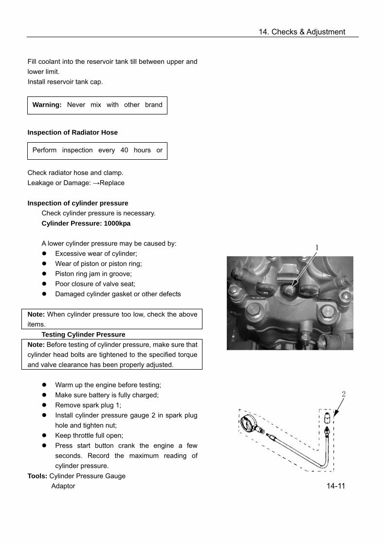
14. Checks & Adjustment
Fill coolant into the reservoir tank till between upper and lower limit. Install reservoir tank cap.
Inspection of Radiator Hose Check radiator hose and clamp. Leakage or Damage: →Replace Inspection of cylinder pressure
Check cylinder pressure is necessary. Cylinder Pressure: 1000kpa A lower cylinder pressure may be caused by:
Excessive wear of cylinder; Wear of piston or piston ring; Piston ring jam in groove; Poor closure of valve seat; Damaged cylinder gasket or other defects
Note: When cylinder pressure too low, check the above items.
Testing Cylinder Pressure Note: Before testing of cylinder pressure, make sure that cylinder head bolts are tightened to the specified torque and valve clearance has been properly adjusted.
Warm up the engine before testing; Make sure battery is fully charged; Remove spark plug 1; Install cylinder pressure gauge 2 in spark plug
hole and tighten nut; Keep throttle full open; Press start button crank the engine a few
seconds. Record the maximum reading of cylinder pressure.
Tools: Cylinder Pressure Gauge Adaptor
14-11
Warning: Never mix with other brand
Perform inspection every 40 hours or

14. Checks & Adjustment
Inspection of Oil Pressure Oil Pressure: 130~170kpa at 3000r/min Lower or higher oil pressure may be caused by:
Oil pressure Ⅰ is too low Clogged oil filter; Leakage from oil passage; Damaged O-ring; Oil pump failure; Combination of above items;
Oil pressure Ⅱ is too high Oil viscosity is too high; Clogged oil passage; Combination of above items;
Testing Oil Pressure Remove bolt①; Connect tachometer with ignition coil② Install oil pressure gauge and joint seat to main oil ③
gallery. Warm up engine as per following:
Summer: 10 minutes at 2000r/min Winter: 20 minutes at 2000r/min After warming up, increase engine speed to 3000r/min, and record readings of oil pressure gauge.
After testing, apply thread locker to the thread in the hole of main oil channel. Install bolt and tighten to the specified torque.
Tighten torque:23N.m Tools:Oil pressure gauge
Tachometer
14-12

14. Checks & Adjustment
Inspection of Clutch Engagement and Lock-up CF188 engine is equipped with a centrifugal type automatic clutch. Before checking the initial engagement and clutch lock-up two inspection checks must be performed to thoroughly check the operation of the drive train. I Initial Engagement Inspection
Connect tachometer to ignition coil Start engine Shift gear lever to “High” position Slowly increase throttle and note down the engine
speed (r/min) when the vehicle starts to move forward.
Engagement speed:1800r/min~2400r/min If the engagement speed is out of the above range, check the following:
Clutch shoes Clutch shoe wheel Primary and secondary sheave
Refer to Chapter 12 for inspection of clutch II Clutch Lock-up Inspection
Connect the tachometer to ignition coil; Start the engine; Shift gear lever to “High” position; Apply front and rear brakes as firmly as possible; Fully open the throttle for a brief period and note the
maximum engine speed obtained during the test cycle.
Lock-up Speed: 3300r/min~3900r/min Warning: Do not apply full power for more than 5 seconds or damage to clutch or engine may occur. If the lock-up speed is out of the above range, check the following:
Clutch shoes Clutch wheel Primary and secondary sheave
Refer to Chapter 12 for inspection of clutch Tool: Tachometer
14-13

15. Engine Removal, Inspection & Installation Δ Engine Removal/Installation Orders and the Relative Page Numbers Item Description Disassembly Inspection /
Maintenance Assembly Remarks
Water Hose/Pipe 15-2 15-11 15-69 Left Side Cover 15-2 — 15-69
Engine Periphery
Recoil Starter 15-2 15-49 15-68 Spark Plug 15-2 15-4 15-68 Cylinder Head Cover 15-3 15-14 15-66 Tensioner 15-3 15-24 15-67 Camshaft 15-3 15-21 15-65 Cylinder Head/Tensioner Plate 15-4 15-15/15-23 15-64 Cylinder/Timing Chain Guide 15-4 15-24/15-23 15-64
Engine Front Side
Piston 15-5 15-25 15-62 Starting Motor 15-5 15-3 15-62 Oil Filter 15-6 15-9 15-62 Sector Gear 15-6 — 15-62 Water Pump 15-7 15-7 15-61 Sheave Drum 15-7 15-48 15-60 Left Crankcase Cover/ Magneto Stator 15-7 15-48 15-60 Magneto Rotor 15-7 15-47 15-60 Starting Driven Gear 15-8 15-47 15-59 Starting Dual Gear/Idle Gear 15-8 15-48 15-59
Engine Left Side
Oil Pump Sprocket and Chain 15-8 — 15-59 CVT Cover 15-9 15-51 15-58 Drive Belt 15-9 15-36 15-57 Primary Sheave/Secondary Sheave 15-9 15-30 15-57 CVT Housing/Clutch Outer Face 15-10 15-51 15-57 Clutch 15-10 15-28 15-56
Engine Right Side
Timing Chain 15-10 15-23 15-56 Gear Position Bolt 15-11 — 15-56 Right Crankcase 15-11 15-52 15-56 Front Output Shaft Components 15-11 15-43 15-55 Driven Bevel Gear Components 15-11 15-43 15-55 Shift Cam 15-12 15-40 15-55 Guide Bar, Fork 15-12 15-39 15-55 Drive Bevel Gear Components 15-12 15-42 15-55 Main Transmission Shaft 15-12 15-38 15-54 Transmission Counter Shaft 15-12 15-38 15-54 Balancer Shaft 15-12 15-46 15-54 Crankshaft 15-13 15-27 15-54 Oil Pump, Pressure-limiting Valve 15-13 15-41 15-53
Engine Center
Left Crankcase 15-52 Notes: Arrowhead direction is for engine removal orders. Reverse the direction for assembly and installation
15-1
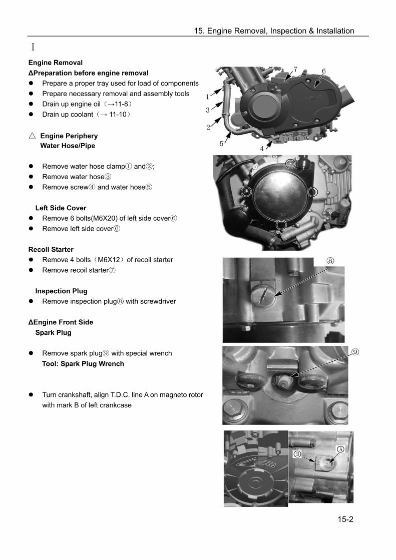
15. Engine Removal, Inspection & Installation
Ⅰ
Engine Removal ΔPreparation before engine removal
Prepare a proper tray used for load of components Prepare necessary removal and assembly tools Drain up engine oil(→11-8) Drain up coolant(→ 11-10)
Engine Periphery
Water Hose/Pipe
Remove water hose clamp and① ②; Remove water hose③ Remove screw④ and water hose⑤
Left Side Cover
Remove 6 bolts(M6X20) of left side cover⑥ Remove left side cover⑥
Recoil Starter
Remove 4 bolts(M6X12)of recoil starter Remove recoil starter⑦
Inspection Plug Remove inspection plug with screwdriver⑧
ΔEngine Front Side Spark Plug
Remove spark plug with special wrench⑨ Tool: Spark Plug Wrench
Turn crankshaft, align T.D.C. line A on magneto rotor with mark B of left crankcase
15-2
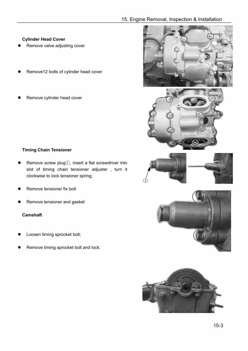
15. Engine Removal, Inspection & Installation Cylinder Head Cover Remove valve adjusting cover
Remove12 bolts of cylinder head cover
Remove cylinder head cover
Timing Chain Tensioner
Remove screw plug , insert ① a flat screwdriver into slot of timing chain tensioner adjuster , turn it clockwise to lock tensioner spring;
Remove tensioner fix bolt
Remove tensioner and gasket
Camshaft Loosen timing sprocket bolt;
Remove timing sprocket bolt and lock;
15-3
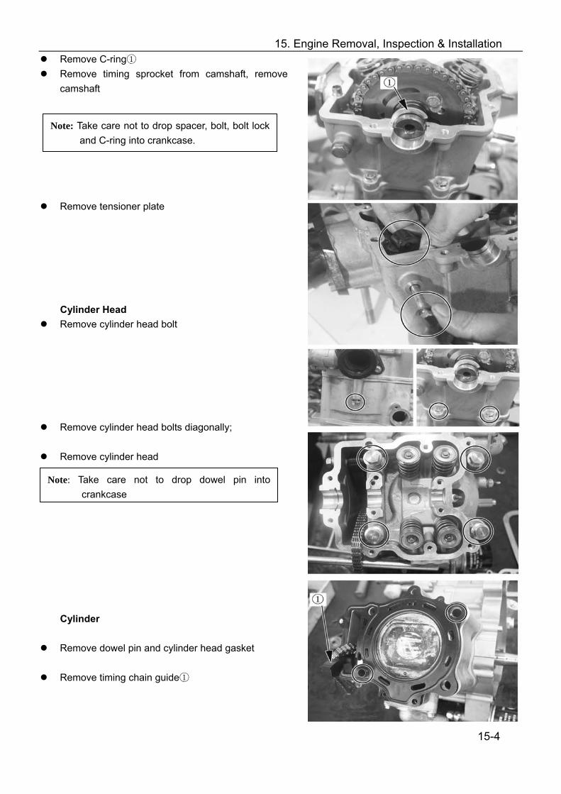
15. Engine Removal, Inspection & Installation Remove C-ring① Remove timing sprocket from camshaft, remove
camshaft
Remove tensioner plate
Cylinder Head Remove cylinder head bolt
Remove cylinder head bolts diagonally;
Remove cylinder head
Cylinder
Remove dowel pin and cylinder head gasket
Remove timing chain guide①
15-4
Note: Take care not to drop spacer, bolt, bolt lock and C-ring into crankcase.
Note: Take care not to drop dowel pin into crankcase
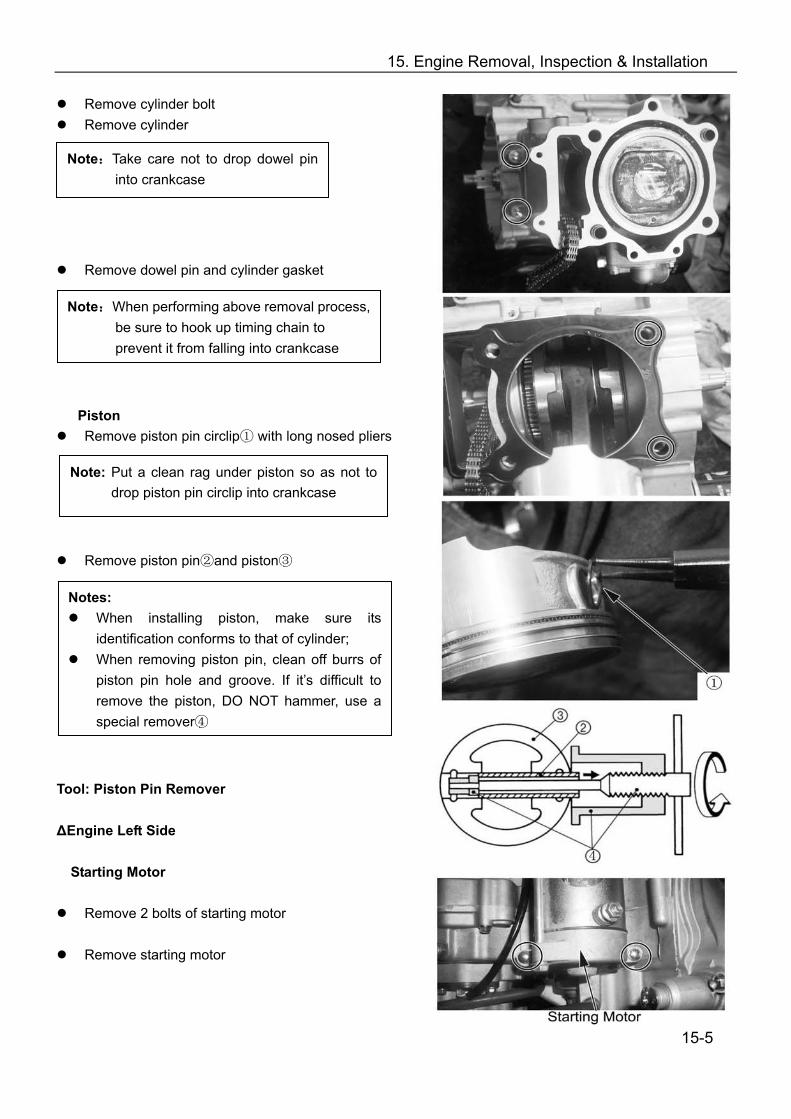
15. Engine Removal, Inspection & Installation
Remove cylinder bolt Remove cylinder
Remove dowel pin and cylinder gasket Piston
Remove piston pin circlip with ① long nosed pliers
Remove piston pin and ② piston③ Tool: Piston Pin Remover ΔEngine Left Side
Starting Motor
Remove 2 bolts of starting motor
Remove starting motor
15-5
Note:Take care not to drop dowel pin into crankcase
Note:When performing above removal process, be sure to hook up timing chain to prevent it from falling into crankcase
Note: Put a clean rag under piston so as not to drop piston pin circlip into crankcase
Notes: When installing piston, make sure its
identification conforms to that of cylinder; When removing piston pin, clean off burrs of
piston pin hole and groove. If it’s difficult to remove the piston, DO NOT hammer, use a special remover④

15. Engine Removal, Inspection & Installation Oil Filter Remove oil filter with special tools
Tool: Oil filter Remover
Sector Gear Remove bolt 1 of gearshift rocker arm Remove gasket 2 and gearshift rocker arm 3
Remove bolt of sector gear housing cover Remove wire clip and sector gear housing cover
Remove dowel pin and gasket Remove drive sector gear 4 Remove bolt 5 of driven sector gear
Remove washer 6 and driven sector 7
15-6
15. Engine Removal, Inspection & Installation Water Pump Screw out bolt of water pump Remove water pump
Sheave Drum Remove the sheave drum by using a suitable bar; Remove washer and sheave drum
Left Crankcase Cover Remove bolts; Remove left crankcase cover Remove dowel pin and gasket
Magneto Rotor Install attachment 1 to crankshaft end
Install special tool to rotor thread; Remove rotor and woodruff key
Tool: Rotor Remover
15-7
15. Engine Removal, Inspection & Installation Starting Motor Gear
Remove driven gear 1 and needle bearing
Remove spacer 2
·Remove dual gear and shaft 3 ·Remove idle gear and shaft 4
Oil Pump Sprocket and Chain
Remove drive sprocket nut 5 Remove C-ring 6 Remove oil pump drive and driven sprockets and
chain
15-8

15. Engine Removal, Inspection & Installation Δ Engine Right Side CVT Cover
Remove bolt of CVT cover Remove CVT cover Remove gasket and dowel pin
CVT(Continuously Variable Transmission)
Remove primary sheave nut with special tool Remove primary sliding sheave
Remove secondary sheave nut with special tools Remove secondary sheave Remove drive belt
Tool: Sheave Holder
Remove primary fixed sheave ①
Remove bolt for air guide plate.
Remove air guide plate
15-9

15. Engine Removal, Inspection & Installation CVT Case
Remove bolt 1 of CVT case Remove nut 2 of CVT case
Remove outer clutch face and CVT case
Remove dowel pin, front and rear gasket Clutch
Remove one-way clutch
Remove clutch shoe fixing nut with special tool
Remove clutch shoe. Note: The clutch shoe nut has left-hand threads. Timing Chain
Remove timing chain
15-10
15. Engine Removal, Inspection & Installation
Engine Center Gear position bolt
Remove gear position bolt 1 Remove spring and steel ball
Right Crankcase Remove left crankcase bolts Remove right crankcase bolts Separate right crankcase with special tool
Caution
The Crankcase separator plate should be parallel with the end face of crankcase
Crankshaft should remain in the left crankcase half.
Tool: Crankcase separator Driven Bevel Gear, Front Output Shaft
Remove bevel gear cover bolt Remove driven bevel gear ③ Remove front output shaft nut ④
15-11
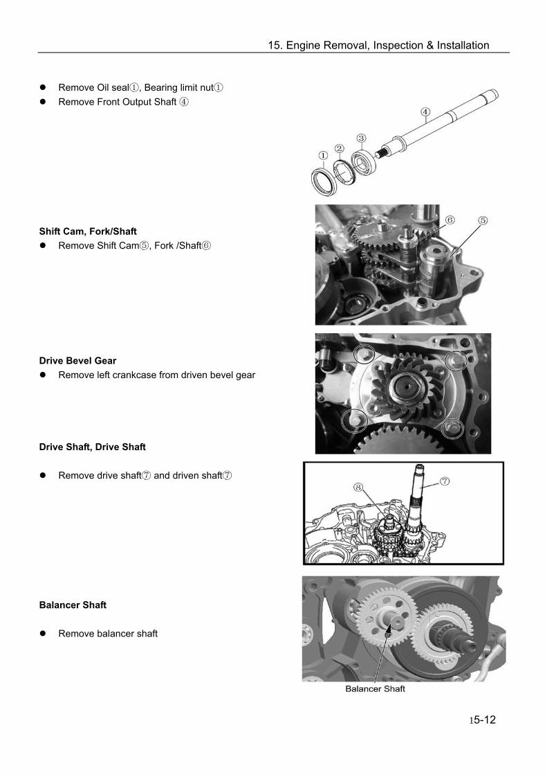
15. Engine Removal, Inspection & Installation
Remove Oil seal①, Bearing limit nut① Remove Front Output Shaft ④
Shift Cam, Fork/Shaft
Remove Shift Cam⑤, Fork /Shaft⑥ Drive Bevel Gear
Remove left crankcase from driven bevel gear Drive Shaft, Drive Shaft
Remove drive shaft⑦ and driven shaft⑦ Balancer Shaft
Remove balancer shaft
15-12
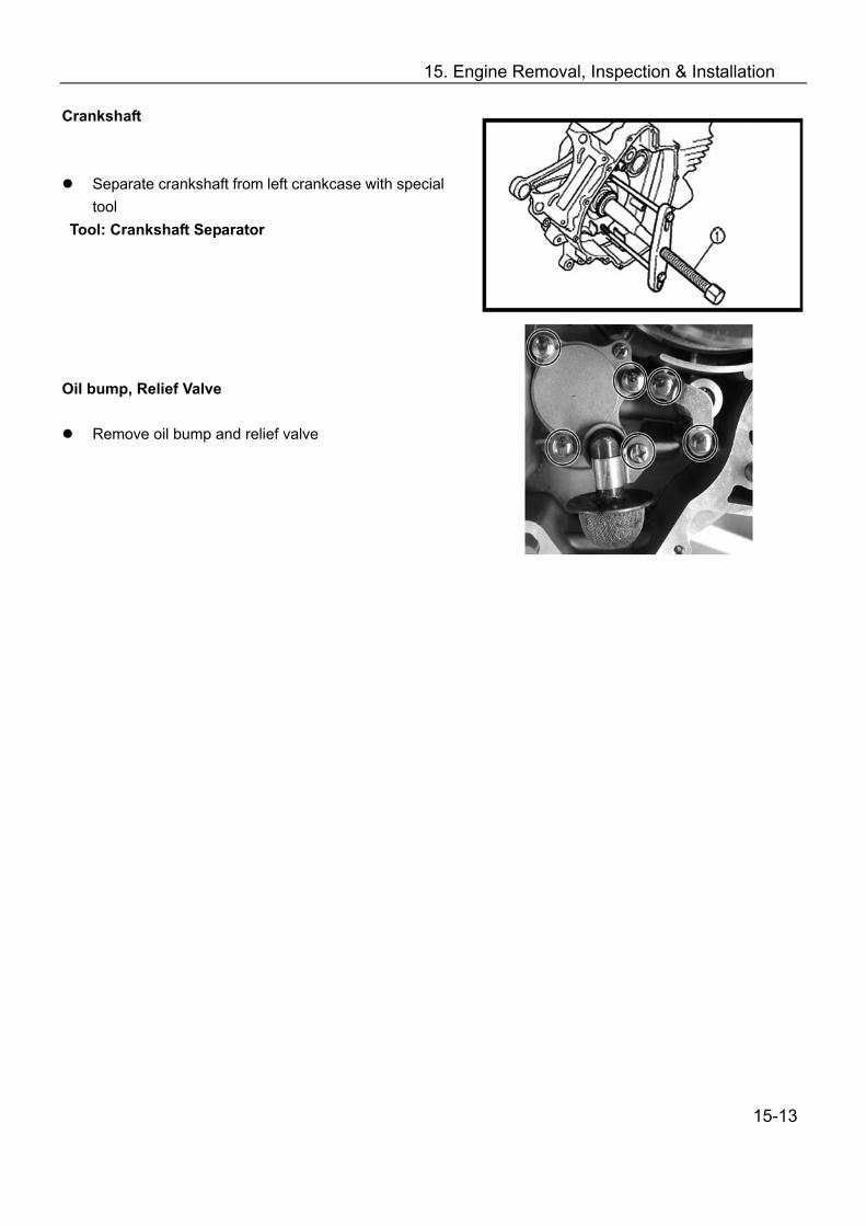
15. Engine Removal, Inspection & Installation
Crankshaft
Separate crankshaft from left crankcase with special tool
Tool: Crankshaft Separator Oil bump, Relief Valve
Remove oil bump and relief valve
15-13
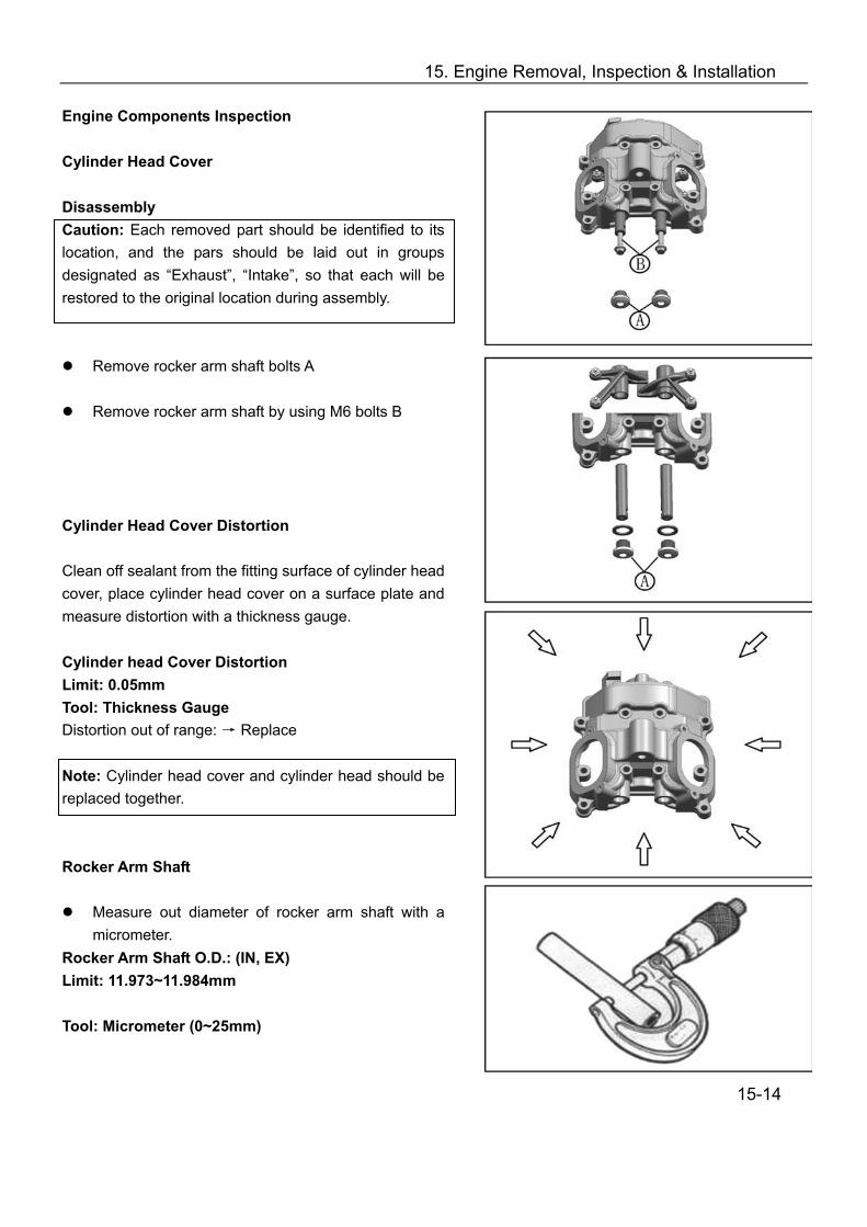
15. Engine Removal, Inspection & Installation
Engine Components Inspection Cylinder Head Cover Disassembly Caution: Each removed part should be identified to its location, and the pars should be laid out in groups designated as “Exhaust”, “Intake”, so that each will be restored to the original location during assembly.
Remove rocker arm shaft bolts A
Remove rocker arm shaft by using M6 bolts B Cylinder Head Cover Distortion Clean off sealant from the fitting surface of cylinder head cover, place cylinder head cover on a surface plate and measure distortion with a thickness gauge. Cylinder head Cover Distortion Limit: 0.05mm Tool: Thickness Gauge Distortion out of range: → Replace Note: Cylinder head cover and cylinder head should be replaced together. Rocker Arm Shaft
Measure out diameter of rocker arm shaft with a micrometer.
Rocker Arm Shaft O.D.: (IN, EX) Limit: 11.973~11.984mm Tool: Micrometer (0~25mm)
15-14

15. Engine Removal, Inspection & Installation
Rocker Arm
When checking the rocker arm, check the inner diameter of the valve rocker arm and wear of the camshaft contact surface.
Rocker Arm I.D. : .000~12.018mm
Tool: Dial Calipers
Assembly
Note: Intake rocker arm shaft A has oil holes.
Apply engine oil to rocker arms and shafts; Install rocker arms and tighten rocker arm shaft to
the specified torque: Rocker Arm Shaft Bolt: 28N.m Cylinder Had Disassembly
Remove intake pipe
Remove water temperature sensor ①and thermostat cover ②
15-15
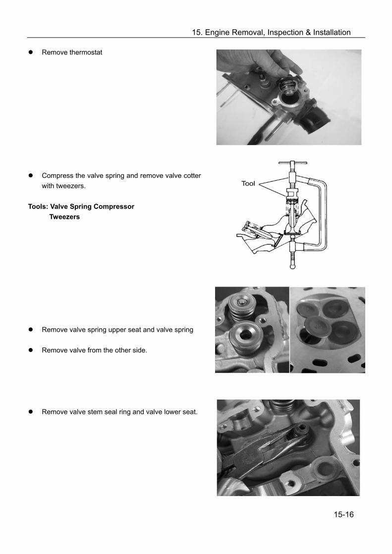
15. Engine Removal, Inspection & Installation
Remove thermostat
Compress the valve spring and remove valve cotter with tweezers.
Tools: Valve Spring Compressor
Tweezers
Remove valve spring upper seat and valve spring
Remove valve from the other side.
Remove valve stem seal ring and valve lower seat.
15-16
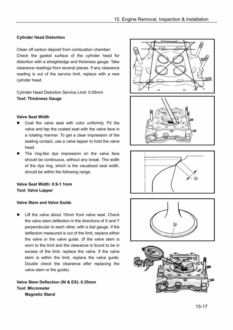
15. Engine Removal, Inspection & Installation
Cylinder Head Distortion Clean off carbon deposit from combustion chamber; Check the gasket surface of the cylinder head for distortion with a straightedge and thickness gauge. Take clearance readings from several places. If any clearance reading is out of the service limit, replace with a new cylinder head. Cylinder Head Distortion Service Limit: 0.05mm Tool: Thickness Gauge Valve Seat Width
Coat the valve seat with color uniformly. Fit the valve and tap the coated seat with the valve face in a rotating manner. To get a clear impression of the seating contact, use a valve lapper to hold the valve head.
The ring-like dye impression on the valve face should be continuous, without any break. The width of the dye ring, which is the visualized seat width, should be within the following range:
Valve Seat Width: 0.9-1.1mm Tool: Valve Lapper Valve Stem and Valve Guide
Lift the valve about 10mm from valve seat. Check the valve stem deflection in the directions of X and Y perpendicular to each other, with a dial gauge. If the deflection measured is out of the limit, replace either the valve or the valve guide. (If the valve stem is worn to the limit and the clearance is found to be in excess of the limit, replace the valve. If the valve stem is within the limit, replace the valve guide. Double check the clearance after replacing the valve stem or the guide).
Valve Stem Deflection (IN & EX): 0.35mm Tool: Micrometer Magnetic Stand 15-17
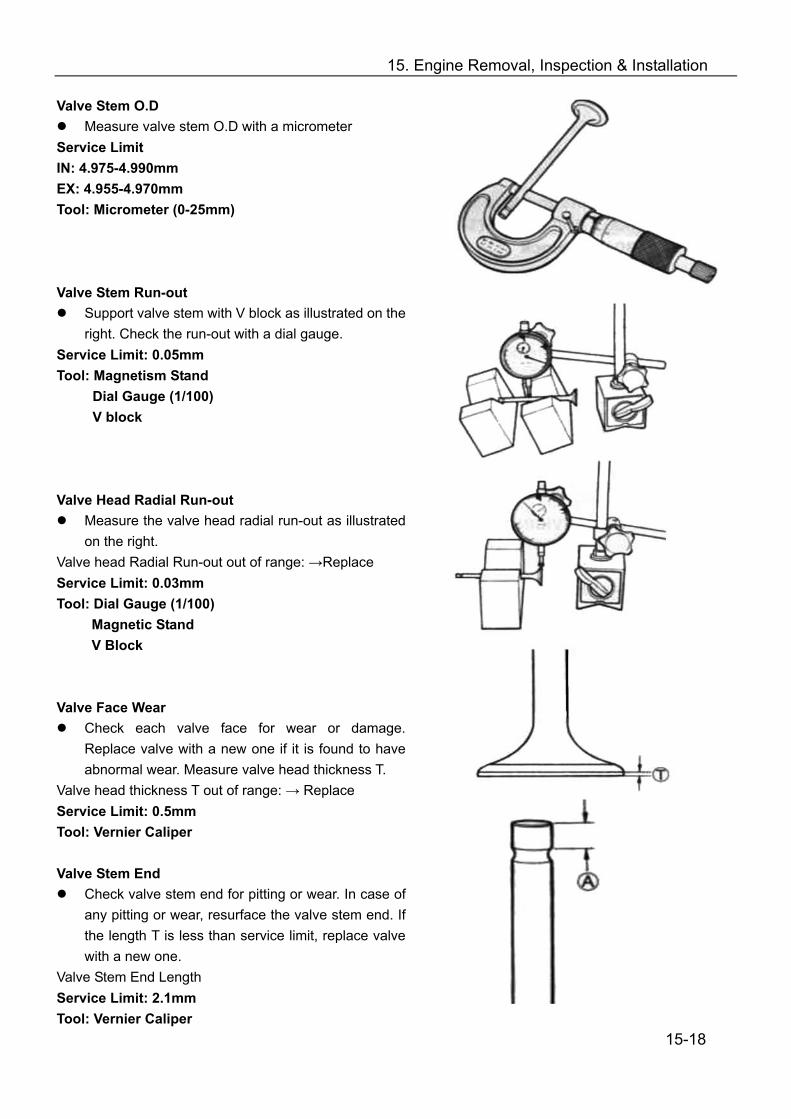
15. Engine Removal, Inspection & Installation
Valve Stem O.D Measure valve stem O.D with a micrometer
Service Limit IN: 4.975-4.990mm EX: 4.955-4.970mm Tool: Micrometer (0-25mm) Valve Stem Run-out
Support valve stem with V block as illustrated on the right. Check the run-out with a dial gauge.
Service Limit: 0.05mm Tool: Magnetism Stand
Dial Gauge (1/100) V block
Valve Head Radial Run-out
Measure the valve head radial run-out as illustrated on the right.
Valve head Radial Run-out out of range: →Replace Service Limit: 0.03mm Tool: Dial Gauge (1/100)
Magnetic Stand V Block
Valve Face Wear
Check each valve face for wear or damage. Replace valve with a new one if it is found to have abnormal wear. Measure valve head thickness T.
Valve head thickness T out of range: → Replace Service Limit: 0.5mm Tool: Vernier Caliper Valve Stem End
Check valve stem end for pitting or wear. In case of any pitting or wear, resurface the valve stem end. If the length T is less than service limit, replace valve with a new one.
Valve Stem End Length Service Limit: 2.1mm Tool: Vernier Caliper
15-18
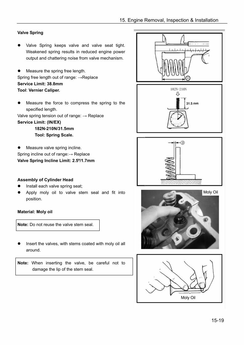
15. Engine Removal, Inspection & Installation
Valve Spring
Valve Spring keeps valve and valve seat tight. Weakened spring results in reduced engine power output and chattering noise from valve mechanism.
Measure the spring free length.
Spring free length out of range: →Replace Service Limit: 38.8mm Tool: Vernier Caliper.
Measure the force to compress the spring to the specified length.
Valve spring tension out of range: → Replace Service Limit: (IN/EX) 182N-210N/31.5mm Tool: Spring Scale.
Measure valve spring incline. Spring incline out of range:→ Replace Valve Spring Incline Limit: 2.5º/1.7mm Assembly of Cylinder Head
Install each valve spring seat; Apply moly oil to valve stem seal and fit into
position. Material: Moly oil Note: Do not reuse the valve stem seal.
Insert the valves, with stems coated with moly oil all around.
Note: When inserting the valve, be careful not to
damage the lip of the stem seal.
15-19
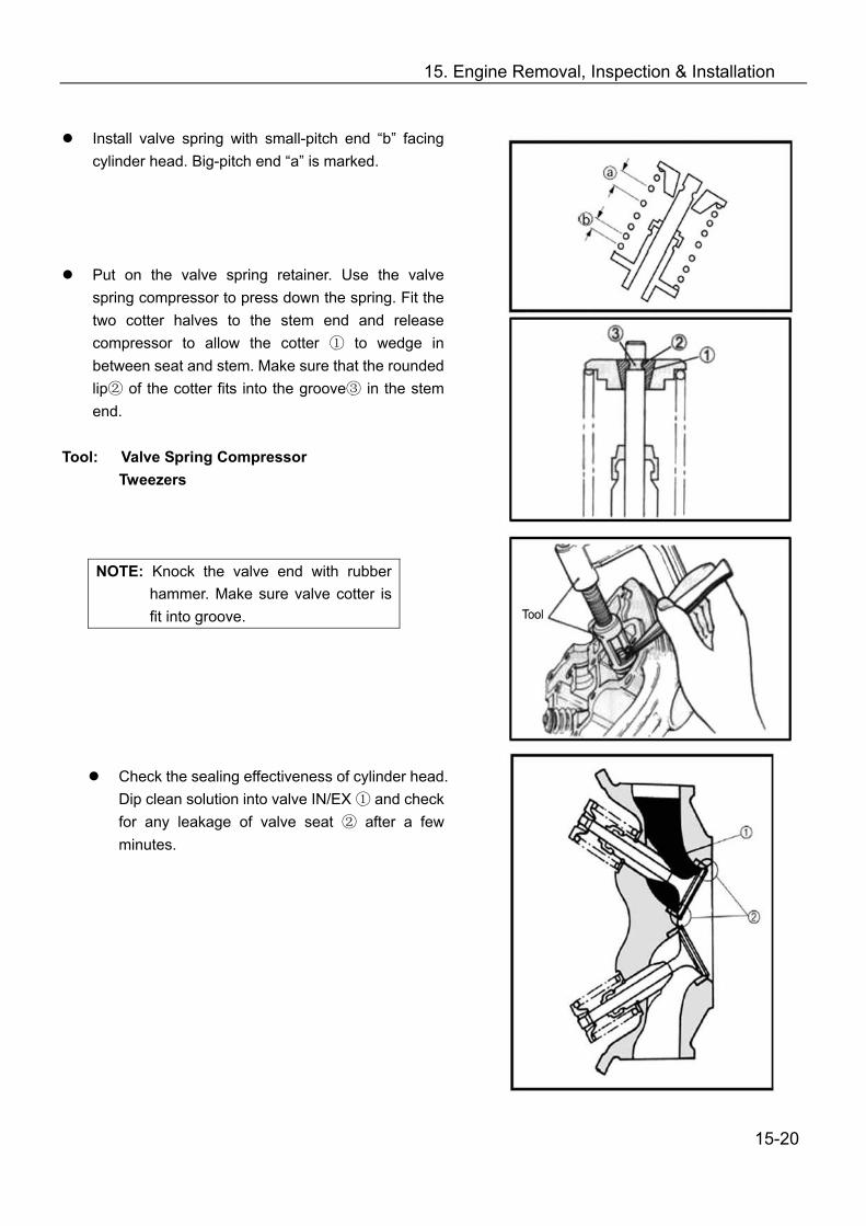
15. Engine Removal, Inspection & Installation
Install valve spring with small-pitch end “b” facing
cylinder head. Big-pitch end “a” is marked.
Put on the valve spring retainer. Use the valve spring compressor to press down the spring. Fit the two cotter halves to the stem end and release compressor to allow the cotter ① to wedge in between seat and stem. Make sure that the rounded lip② of the cotter fits into the groove③ in the stem end.
Tool: Valve Spring Compressor
Tweezers NOTE: Knock the valve end with rubber
hammer. Make sure valve cotter is fit into groove.
Check the sealing effectiveness of cylinder head. Dip clean solution into valve IN/EX ① and check for any leakage of valve seat ② after a few minutes.
15-20
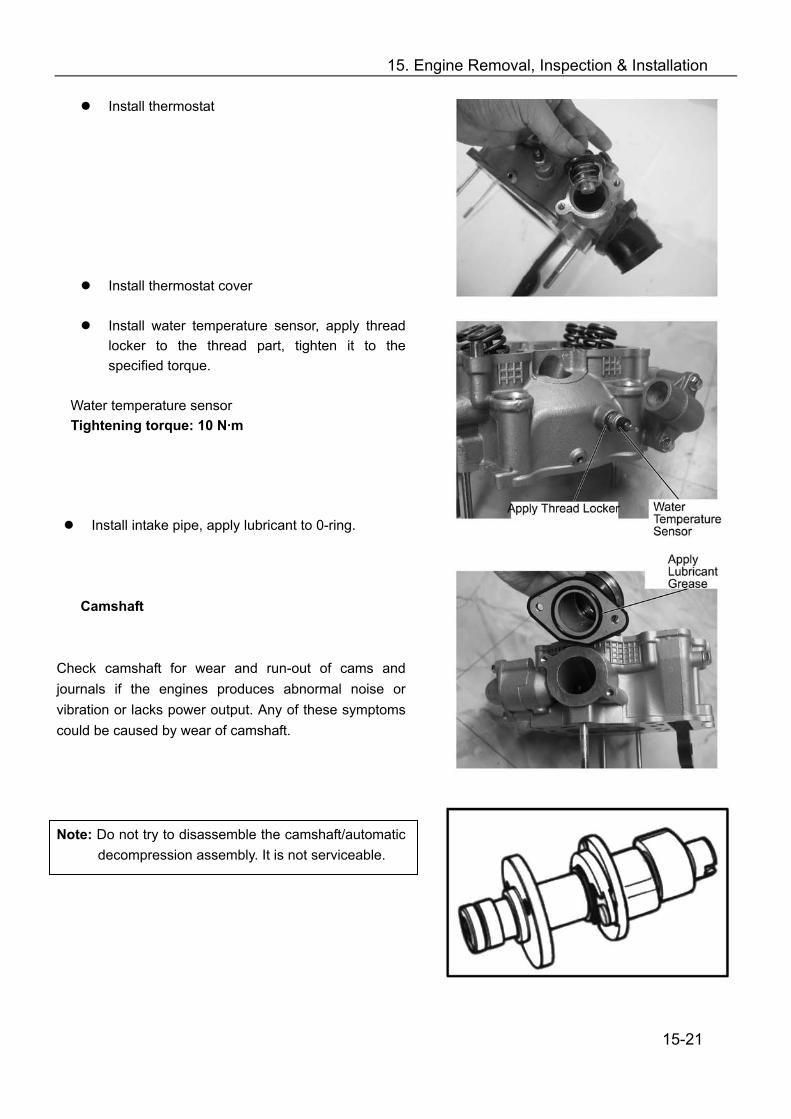
15. Engine Removal, Inspection & Installation
Install thermostat
Install thermostat cover
Install water temperature sensor, apply thread locker to the thread part, tighten it to the specified torque.
Water temperature sensor Tightening torque: 10 N·m Install intake pipe, apply lubricant to 0-ring.
Camshaft
Check camshaft for wear and run-out of cams and journals if the engines produces abnormal noise or vibration or lacks power output. Any of these symptoms could be caused by wear of camshaft. Note: Do not try to disassemble the camshaft/automatic
decompression assembly. It is not serviceable.
15-21

15. Engine Removal, Inspection & Installation
Automatic Decompression Move the automatic decompression weight with
hand and check if it is operating smoothly. If it is not working smoothly, replace with a new camshaft/automatic decompression assembly.
Cam Wear
Worn cams can often cause mistimed valve operation resulting in reduced power output. The limit of cam wear is specified for both IN and EX cams in terms of cam height “a”. Measure with a micrometer the cam height. Cam height out of range: →Replace Cam height service limit: IN: 33.130mm EX: 33.200mm
Tool: micrometer (25-50mm) Camshaft Journal Wear
Check whether each journal is worn to the limit by measuring camshaft journal oil clearance with the camshaft installed.
Camshaft journal oil clearance Service limit: 0.15mm
Check according to the following steps: Clean off materials from cylinder head and cover; Install camshaft with plastic gauge; Install cylinder head cover and tighten bolts evenly
and diagonally to the specified torque: Tightening torque: 10 N·m
Remove cylinder head cover, read the width of the compressed plastic gauge with envelop scale. The reading should be taken from the widest part.
Tool: Plastid Gauge Note: Do not turn the camshaft with plastic gauge in
place. If the camshaft journal oil clearance exceeds the limit, measure the outer diameter of camshaft; Replace either cylinder head set or the camshaft if the
clearance is not correct. 15-22
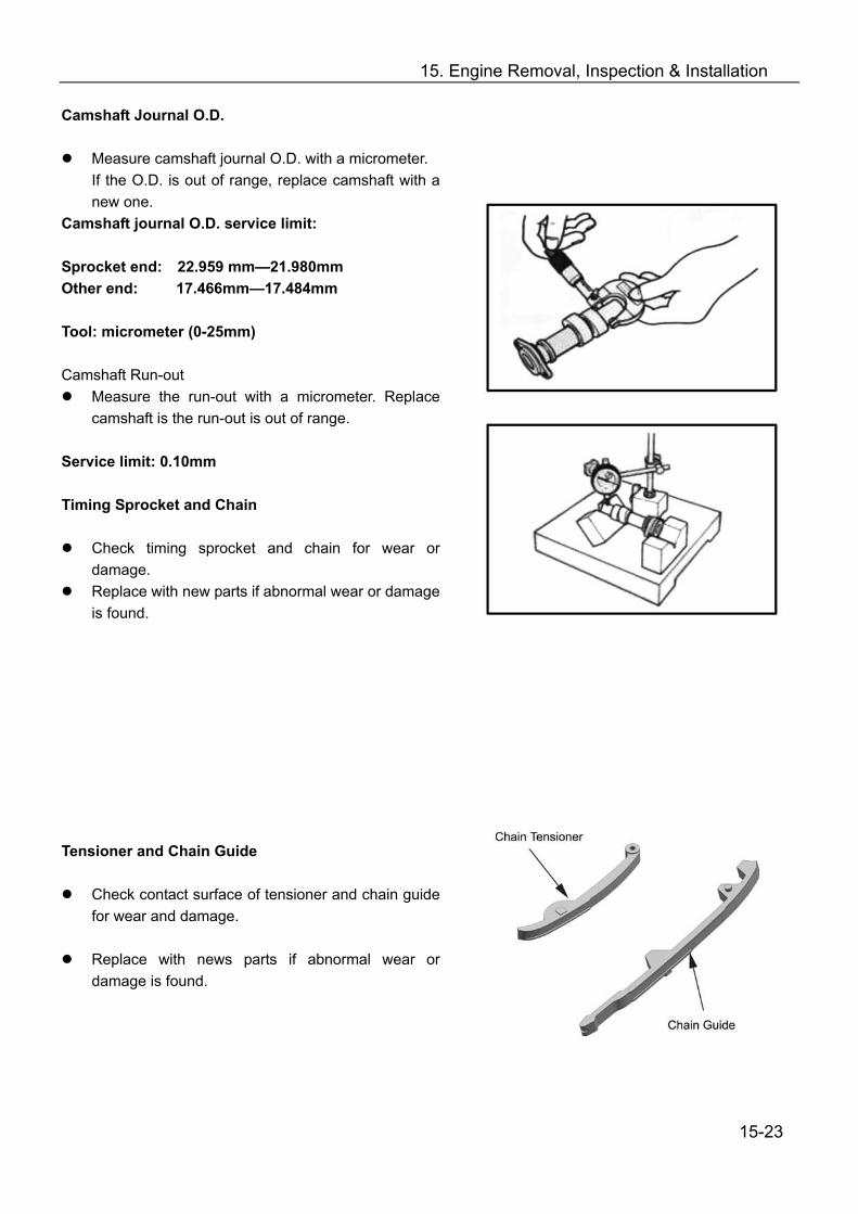
15. Engine Removal, Inspection & Installation
Camshaft Journal O.D.
Measure camshaft journal O.D. with a micrometer. If the O.D. is out of range, replace camshaft with a new one.
Camshaft journal O.D. service limit: Sprocket end: 22.959 mm—21.980mm Other end: 17.466mm—17.484mm
Tool: micrometer (0-25mm)
Camshaft Run-out
Measure the run-out with a micrometer. Replace camshaft is the run-out is out of range.
Service limit: 0.10mm Timing Sprocket and Chain
Check timing sprocket and chain for wear or damage.
Replace with new parts if abnormal wear or damage is found.
Tensioner and Chain Guide
Check contact surface of tensioner and chain guide for wear and damage.
Replace with news parts if abnormal wear or
damage is found.
15-23
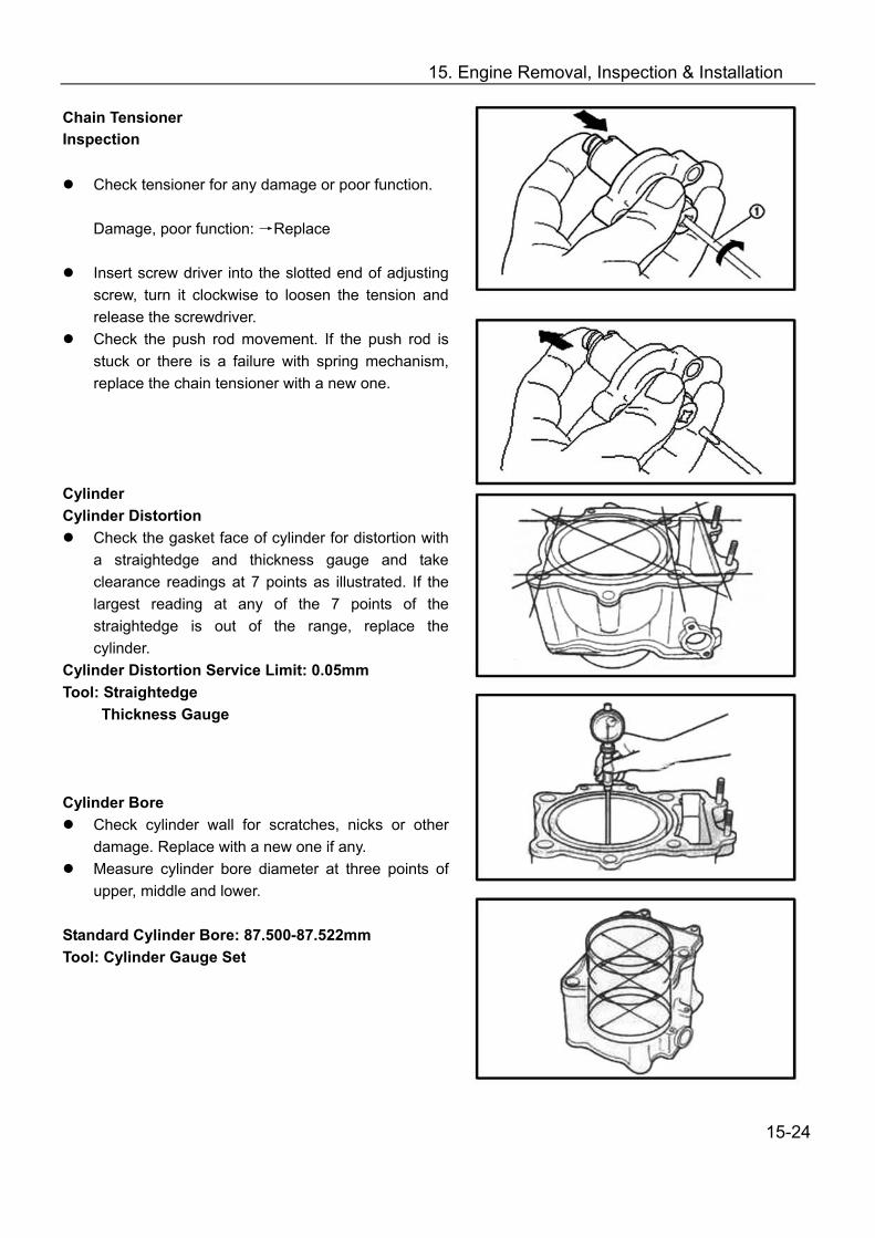
15. Engine Removal, Inspection & Installation
Chain Tensioner Inspection
Check tensioner for any damage or poor function.
Damage, poor function: →Replace
Insert screw driver into the slotted end of adjusting screw, turn it clockwise to loosen the tension and release the screwdriver.
Check the push rod movement. If the push rod is stuck or there is a failure with spring mechanism, replace the chain tensioner with a new one.
Cylinder Cylinder Distortion
Check the gasket face of cylinder for distortion with a straightedge and thickness gauge and take clearance readings at 7 points as illustrated. If the largest reading at any of the 7 points of the straightedge is out of the range, replace the cylinder.
Cylinder Distortion Service Limit: 0.05mm Tool: Straightedge Thickness Gauge Cylinder Bore
Check cylinder wall for scratches, nicks or other damage. Replace with a new one if any.
Measure cylinder bore diameter at three points of upper, middle and lower.
Standard Cylinder Bore: 87.500-87.522mm Tool: Cylinder Gauge Set
15-24
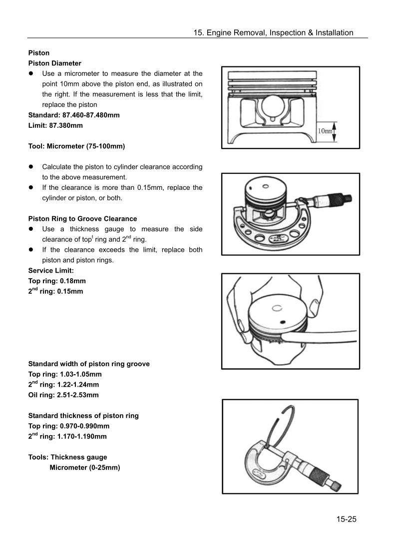
15. Engine Removal, Inspection & Installation
Piston Piston Diameter
Use a micrometer to measure the diameter at the point 10mm above the piston end, as illustrated on the right. If the measurement is less that the limit, replace the piston
Standard: 87.460-87.480mm Limit: 87.380mm Tool: Micrometer (75-100mm)
Calculate the piston to cylinder clearance according to the above measurement.
If the clearance is more than 0.15mm, replace the cylinder or piston, or both.
Piston Ring to Groove Clearance
Use a thickness gauge to measure the side clearance of topt ring and 2nd ring.
If the clearance exceeds the limit, replace both piston and piston rings.
Service Limit: Top ring: 0.18mm 2nd ring: 0.15mm Standard width of piston ring groove Top ring: 1.03-1.05mm 2nd ring: 1.22-1.24mm Oil ring: 2.51-2.53mm Standard thickness of piston ring Top ring: 0.970-0.990mm 2nd ring: 1.170-1.190mm Tools: Thickness gauge
Micrometer (0-25mm)
15-25
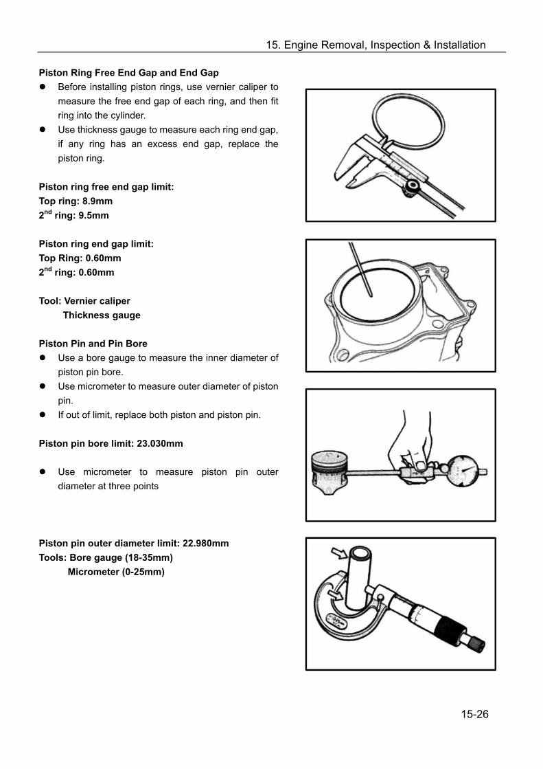
15. Engine Removal, Inspection & Installation
Piston Ring Free End Gap and End Gap Before installing piston rings, use vernier caliper to
measure the free end gap of each ring, and then fit ring into the cylinder.
Use thickness gauge to measure each ring end gap, if any ring has an excess end gap, replace the piston ring.
Piston ring free end gap limit: Top ring: 8.9mm 2nd ring: 9.5mm Piston ring end gap limit: Top Ring: 0.60mm 2nd ring: 0.60mm Tool: Vernier caliper
Thickness gauge Piston Pin and Pin Bore
Use a bore gauge to measure the inner diameter of piston pin bore.
Use micrometer to measure outer diameter of piston pin.
If out of limit, replace both piston and piston pin. Piston pin bore limit: 23.030mm
Use micrometer to measure piston pin outer diameter at three points
Piston pin outer diameter limit: 22.980mm Tools: Bore gauge (18-35mm)
Micrometer (0-25mm)
15-26
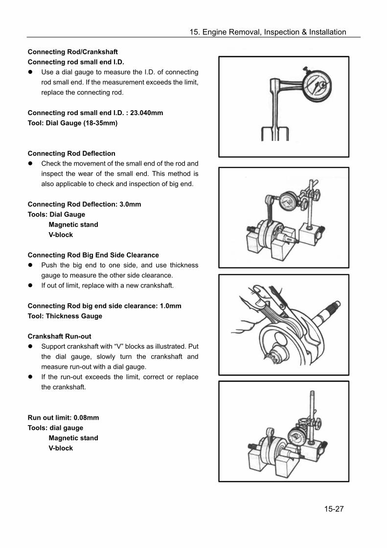
15. Engine Removal, Inspection & Installation
Connecting Rod/Crankshaft Connecting rod small end I.D.
Use a dial gauge to measure the I.D. of connecting rod small end. If the measurement exceeds the limit, replace the connecting rod.
Connecting rod small end I.D. : 23.040mm Tool: Dial Gauge (18-35mm) Connecting Rod Deflection
Check the movement of the small end of the rod and inspect the wear of the small end. This method is also applicable to check and inspection of big end.
Connecting Rod Deflection: 3.0mm Tools: Dial Gauge
Magnetic stand V-block
Connecting Rod Big End Side Clearance
Push the big end to one side, and use thickness gauge to measure the other side clearance.
If out of limit, replace with a new crankshaft. Connecting Rod big end side clearance: 1.0mm Tool: Thickness Gauge Crankshaft Run-out
Support crankshaft with “V” blocks as illustrated. Put the dial gauge, slowly turn the crankshaft and measure run-out with a dial gauge.
If the run-out exceeds the limit, correct or replace the crankshaft.
Run out limit: 0.08mm Tools: dial gauge
Magnetic stand V-block
15-27

15. Engine Removal, Inspection & Installation
Clutch Clutch Shoes
Check clutch for chipping, scrape, uneven wear or heat discoloration. At the same time check depth of the grooves of clutch shoes. If any of the clutch shoes has no groove, replace the clutch.
Note: clutch should be replaced as a set.
Clutch Wheel Check the inner clutch wheel ① for scratches, scuffs or blue discoloration or uneven wear. If any damage is found, replace the clutch wheel with a new one.
Check oil seal lip for wear or damage. Wear or Damage: →Replace
Use special tool to remove oil seal Tool: Oil seal remover
Use special tool to assemble oil seal Tool: Oil seal installer set
Check the turning of bearing. Abnormal damage: →Replace Assembly
Apply lubricant grease to oil seal when assembling.
15-28

15. Engine Removal, Inspection & Installation
Primary and Secondary Sheave
15-29

15. Engine Removal, Inspection & Installation
Primary Sliding Sheave Disassembly
Remove spacer Remove Cam ①and Roller②
Roller
Check each roller and sliding face for wear and damage.
Wear and damage: →Replace Note: rollers should be replaced as a set.
Oil Seal Check oil seal lip for wear and damage.
Wear and damage: →Replace
Remove the oil seal
15-30

15. Engine Removal, Inspection & Installation
Primary Sliding Sheave and Fixed Sheave Check the drive face for any abnormal conditions
such as damage or stepped wearing. Damage or wearing: → Replace
Install oil seal with special tool. Tool: Bearing install set Tool Tool Assembly Reverse the removal procedure of primary sliding and fixed sheave for installation. Pay attention to the following:
Apply grease to inner bore and oil seal lip. Note: Wipe off any excessive grease thoroughly. Take care not to attach any lubricant grease
to contact surface of drive belt.
Material: Lubricant grease
Position 8 rollers ①on the primary sliding sheave
Install 4 dampers ② to cam ③ Install cam to primary sliding sheave.
Notes: When inserting the spacer, press down the cam so that the rollers will not come out of position.
15-31
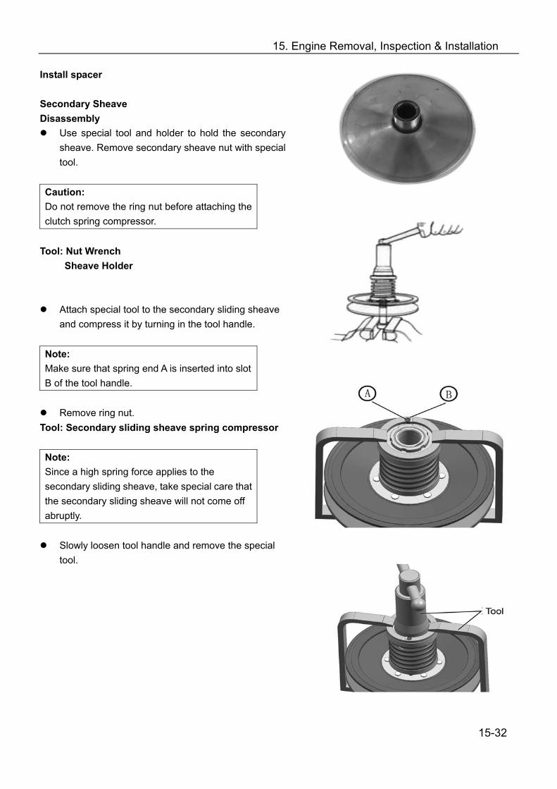
15. Engine Removal, Inspection & Installation
Install spacer Secondary Sheave Disassembly
Use special tool and holder to hold the secondary sheave. Remove secondary sheave nut with special tool.
Caution: Do not remove the ring nut before attaching the clutch spring compressor.
Tool: Nut Wrench Sheave Holder
Attach special tool to the secondary sliding sheave and compress it by turning in the tool handle.
Note: Make sure that spring end A is inserted into slot B of the tool handle.
Remove ring nut.
Tool: Secondary sliding sheave spring compressor Note: Since a high spring force applies to the secondary sliding sheave, take special care that the secondary sliding sheave will not come off abruptly.
Slowly loosen tool handle and remove the special
tool. tool
15-32

15. Engine Removal, Inspection & Installation
Remove spring ① Remove spring seat .②
Remove guide pin and spacer.
Remove secondary sliding sheave ③ O-ring and Oil Seal Check the O-ring and oil seal for wear and damage. O-ring oil seal Wear and Damage: → Replace
Remove Oil Seal
15-33
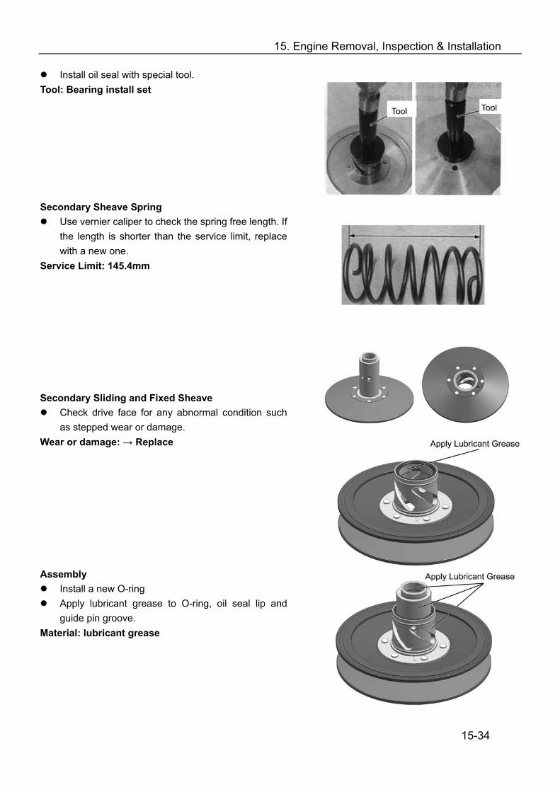
15. Engine Removal, Inspection & Installation
Install oil seal with special tool. Tool: Bearing install set tool tool Secondary Sheave Spring
Use vernier caliper to check the spring free length. If the length is shorter than the service limit, replace with a new one.
Service Limit: 145.4mm lubricant grease Secondary Sliding and Fixed Sheave
Check drive face for any abnormal condition such as stepped wear or damage.
Wear or damage: → Replace Lubricant grease Assembly
Install a new O-ring Apply lubricant grease to O-ring, oil seal lip and
guide pin groove. Material: lubricant grease
15-34
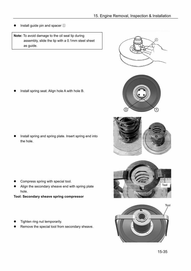
15. Engine Removal, Inspection & Installation
Install guide pin and spacer ① Note: To avoid damage to the oil seal lip during
assembly, slide the lip with a 0.1mm steel sheet as guide.
Install spring seat. Align hole A with hole B.
Install spring and spring plate. Insert spring end into the hole.
Compress spring with special tool. Align the secondary sheave end with spring plate
hole. Tool: Secondary sheave spring compressor tool
Tighten ring nut temporarily. tool Remove the special tool from secondary sheave.
15-35
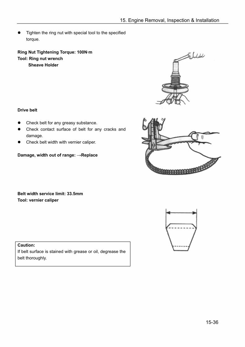
15. Engine Removal, Inspection & Installation
Tighten the ring nut with special tool to the specified torque.
Ring Nut Tightening Torque: 100N·m Tool: Ring nut wrench
Sheave Holder Drive belt
Check belt for any greasy substance. Check contact surface of belt for any cracks and
damage. Check belt width with vernier caliper.
Damage, width out of range: →Replace Belt width service limit: 33.5mm Tool: vernier caliper Caution: If belt surface is stained with grease or oil, degrease the belt thoroughly.
15-36
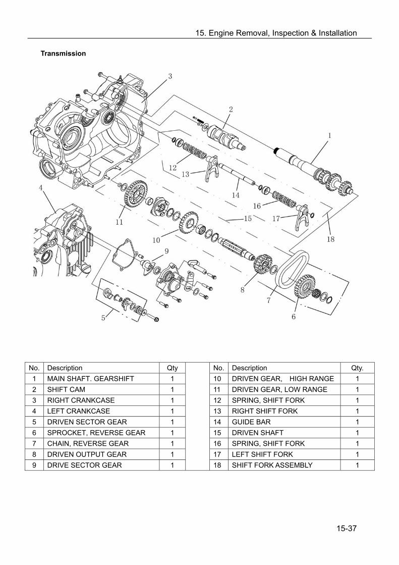
15. Engine Removal, Inspection & Installation
Transmission
No. Description Qty No. Description Qty. 1 MAIN SHAFT. GEARSHIFT 1 10 DRIVEN GEAR, HIGH RANGE 1 2 SHIFT CAM 1 11 DRIVEN GEAR, LOW RANGE 1 3 RIGHT CRANKCASE 1 12 SPRING, SHIFT FORK 1 4 LEFT CRANKCASE 1 13 RIGHT SHIFT FORK 1 5 DRIVEN SECTOR GEAR 1 14 GUIDE BAR 1 6 SPROCKET, REVERSE GEAR 1 15 DRIVEN SHAFT 1 7 CHAIN, REVERSE GEAR 1 16 SPRING, SHIFT FORK 1 8 DRIVEN OUTPUT GEAR 1 17 LEFT SHIFT FORK 1 9 DRIVE SECTOR GEAR 1
18 SHIFT FORK ASSEMBLY 1 15-37

15. Engine Removal, Inspection & Installation
Inspection Check main shaft gear and sprocket surface for any
damage or over wear. Damage or over wear: → Replace
Check reverse gear chain for any damage or over wear.
Damage or over wear: → Replace
Disassemble driven shaft as illustrated.
Check each gear surface for any damage or over wear.
Check bearing and collar for any wear or damage.. Damage or over wear: → Replace
15-38
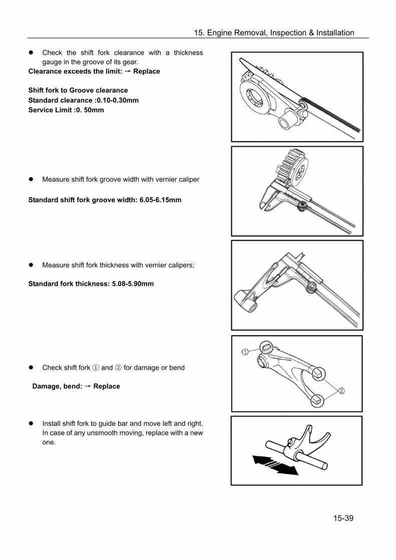
15. Engine Removal, Inspection & Installation
Check the shift fork clearance with a thickness gauge in the groove of its gear.
Clearance exceeds the limit: → Replace
Shift fork to Groove clearance Standard clearance :0.10-0.30mm Service Limit :0. 50mm
Measure shift fork groove width with vernier caliper Standard shift fork groove width: 6.05-6.15mm
Measure shift fork thickness with vernier calipers; Standard fork thickness: 5.08-5.90mm
Check shift fork and for damage ① ② or bend Damage, bend: → Replace
Install shift fork to guide bar and move left and right. In case of any unsmooth moving, replace with a new one.
15-39

15. Engine Removal, Inspection & Installation
Put the guide bar on a flat plate and roll it. In case of any bend, replace with a new one.
NOTE:DON NOT attempt to correct a bent guide bar.
Check shift fork spring for breakage, damage Broken or damaged: → Replace
Check shift cam groove for scratches, damage. Scratch or damage: → Replace
Assembly Reverse the removal procedure for assembly. Pay attention to the following:
Use new retainers. Pay attention to the direction of the retainers. Fit to the side where the thrust is as illustrated.
Coat the gears and shafts with engine oil before
assembly. Note:
Do not reuse the retainers Do not expand of the gap end of new retainers too
wide when assembling. Make sure that all the retainers are properly fitted.
15-40
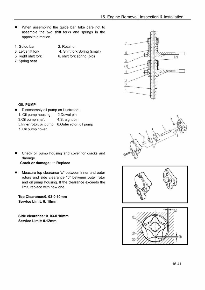
15. Engine Removal, Inspection & Installation
When assembling the guide bar, take care not to assemble the two shift forks and springs in the opposite direction.
1. Guide bar 2. Retainer 3. Left shift fork 4. Shift fork Spring (small) 5. Right shift fork 6. shift fork spring (big) 7. Spring seat
OIL PUMP Disassembly oil pump as illustrated: 1. Oil pump housing 2.Dowel pin 3.Oil pump shaft 4.Straight pin 5.Inner rotor, oil pump 6.Outer rotor, oil pump 7. Oil pump cover
Check oil pump housing and cover for cracks and damage.
Crack or damage: → Replace
Measure top clearance “a” between inner and outer rotors and side clearance “b” between outer rotor and oil pump housing. If the clearance exceeds the limit, replace with new one.
Top Clearance:0. 03-0.10mm Service Limit: 0. 15mm Side clearance: 0. 03-0.10mm Service Limit: 0.12mm
15-41
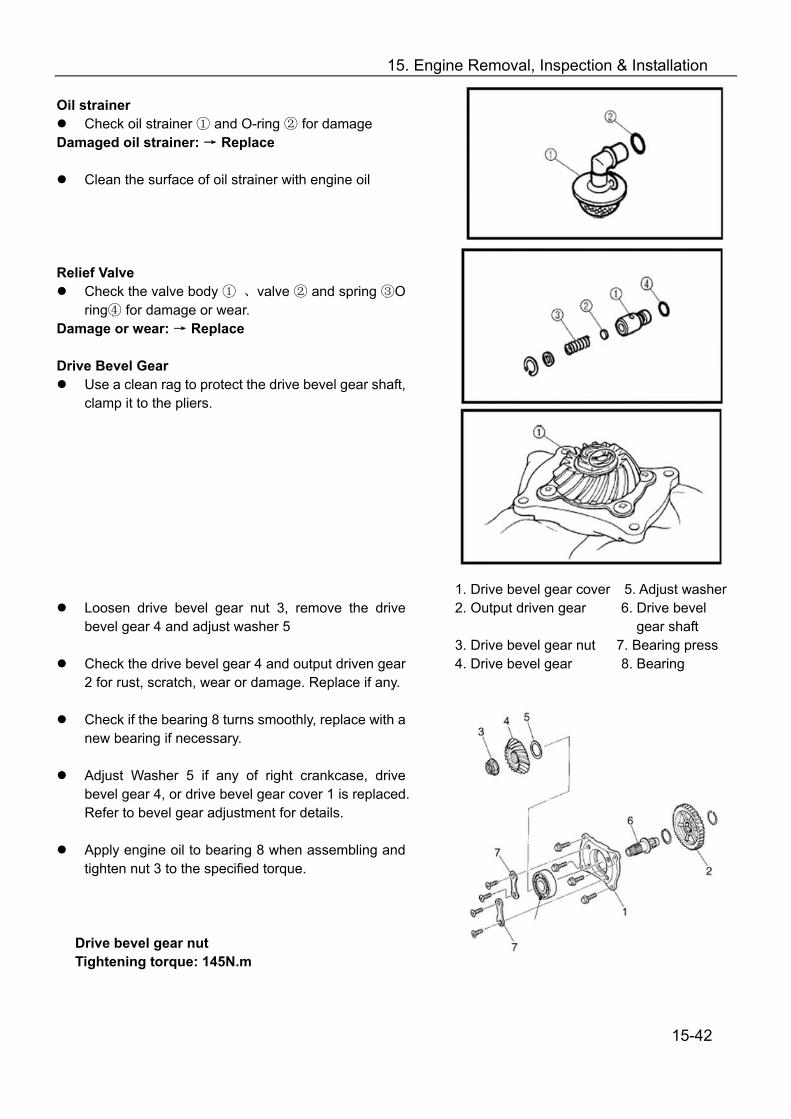
15. Engine Removal, Inspection & Installation
Oil strainer Check oil strainer and ① O-ring for damage②
Damaged oil strainer: → Replace
Clean the surface of oil strainer with engine oil
Relief Valve Check the valve body ① 、valve and spring O ② ③
ring for damage or wear④ . Damage or wear: → Replace
Drive Bevel Gear
Use a clean rag to protect the drive bevel gear shaft, clamp it to the pliers.
Loosen drive bevel gear nut 3, remove the drive bevel gear 4 and adjust washer 5
Check the drive bevel gear 4 and output driven gear
2 for rust, scratch, wear or damage. Replace if any.
Check if the bearing 8 turns smoothly, replace with a new bearing if necessary.
Adjust Washer 5 if any of right crankcase, drive
bevel gear 4, or drive bevel gear cover 1 is replaced. Refer to bevel gear adjustment for details.
Apply engine oil to bearing 8 when assembling and
tighten nut 3 to the specified torque.
Drive bevel gear nut Tightening torque: 145N.m
1. Drive bevel gear cover 5. Adjust washer 2. Output driven gear 6. Drive bevel
gear shaft 3. Drive bevel gear nut 7. Bearing press 4. Drive bevel gear 8. Bearing 15-42
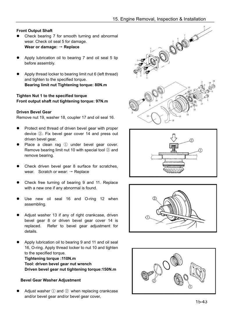
15. Engine Removal, Inspection & Installation
Front Output Shaft Check bearing 7 for smooth turning and abnormal
wear. Check oil seal 5 for damage. Wear or damage: → Replace
Apply lubrication oil to bearing 7 and oil seal 5 lip
before assembly.
Apply thread locker to bearing limit nut 6 (left thread) and tighten to the specified torque. Bearing limit nut Tightening torque: 80N.m
Tighten Nut 1 to the specified torque Front output shaft nut tightening torque: 97N.m
Driven Bevel Gear Remove nut 19, washer 18, coupler 17 and oil seal 16.
Protect end thread of driven bevel gear with proper device ②. Fix bevel gear cover 14 and press out driven bevel gear.
Place a clean rag ① under bevel gear cover. Remove bearing limit nut 10 with special tool ② and remove bearing.
Check driven bevel gear 8 surface for scratches,
wear. Scratch or wear: → Replace
Check free turning of bearing 9 and 11. Replace with a new one if any abnormal is found.
Use new oil seal 16 and O-ring 12 when
assembling.
Adjust washer 13 if any of right crankcase, driven bevel gear 8 or driven bevel gear cover 14 is replaced. Refer to bevel gear adjustment for details.
Apply lubrication oil to bearing 9 and 11 and oil seal
16, O-ring. Apply thread locker to nut 10 and tighten to the specified torque. Tightening torque :110N.m Tool: driven bevel gear nut wrench Driven bevel gear nut tightening torque:150N.m
Bevel Gear Washer Adjustment
Adjust washer ① and ② when replacing crankcase
and/or bevel gear and/or bevel gear cover,
15-43
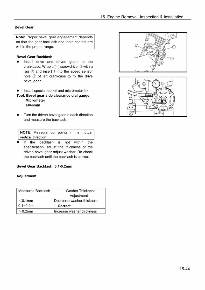
15. Engine Removal, Inspection & Installation
Bevel Gear Note: Proper bevel gear engagement depends on that the gear backlash and tooth contact are within the proper range.
Bevel Gear Backlash
Install drive and driven gears to the crankcase. Wrap a (--) screwdriver ③with a rag ② and insert it into the speed sensor hole ① of left crankcase to fix the drive bevel gear.
Install special tool ③ and micrometer ④.
Tool: Bevel gear side clearance dial gauge Micrometer a=46mm
Turn the driven bevel gear in each direction and measure the backlash.
If the backlash is not within the specification, adjust the thickness of the driven bevel gear adjust washer. Re-check the backlash until the backlash is correct.
Bevel Gear Backlash: 0.1-0.2mm Adjustment
NOTE: Measure four points in the mutual vertical direction
Measured Backlash Washer Thickness Adjustment
<0.1mm Decrease washer thickness 0.1~0.2m Correct >0.2mm Increase washer thickness
15-44

15. Engine Removal, Inspection & Installation
Tooth Contact After adjusting the backlash, check the tooth contact
according to the following procedures:
Remove drive and driven bevel gear shafts from crankcase;
Clean and degrease every tooh of drive and driven bevel gear;
Coat the driven bevel gear with machinist’s layout
dye or paste;
Install drive and driven bevel gear;
Rotate the driven bevel gear several turns in both directions;
Remove drive and driven bevel gear shafts and check the coated teeth of the drive bevel gear;
Refer to the illustration on the right for tooth contact
pattern ①, ② and ③ ① Incorrect (contact at tooth top) ② Correct ③ Incorrect (contact at tooth bottom)
If tooth contact is correct (Contact ②), continue the next procedure.
If tooth contact is not correct (② and ③), adjust the thickness of the washer of drive bevel gear. Repeat above steps to check tooth contact until it is correct.
Adjustment Tooth Contact Washer Adjustment Contact at tooth top ① Increase Thickness Contact at tooth bottom ③
Decrease Thickness
Note:
After adjusting the tooth contact, the backlash must be checked again;
If the backlash is adjusted but tooth contact is still out of specification, replace the drive and driven bevel gears;
Both tooth contact and backlash should be within the required specification.
15-45

15. Engine Removal, Inspection & Installation
Balancer Shaft Remove the parts as illustrated on the right. Check
each part for abnormal wear or damage. Wear or damage: → Replace
① Balancer shaft gear ② Woodruff key ③ Balancer shaft ④ Balancer shaft sprocket ⑤ Washer ⑥ Bolt Magneto Rotor
Remove starter clutch nut;
15-46

15. Engine Removal, Inspection & Installation
Check starter clutch roller and holder for abnormal wear or damage. Wear or damage: → Replace
Install the starter clutch in the correct direction. Note: When install the starter clutch to the magneto rotor, make sure side “A” is in the right direction.
Face arrow mark “B” to the engine side; Apply engine oil to starter clutch.
Apply thread locker to bolt and tighten to the
specified torque: Tightening torque of starter clutch bolt: 26N.m Material: Thread Locker
Install the starter driven gear
Make that the starter driven gear turns in the opposite direction of the arrow mark “B”. The gear cannot turn in the direction of the arrow.
Check starter driven gear bearing. In case of anything unusual, replace the bearing.
Remove starter driven gear bearing with special tool
Install starter driven gear bearing with special tool. Tool: Bearing Installer/Remover
15-47

15. Engine Removal, Inspection & Installation
Electric Starter Gear Check the gear surface for scrap or damage.
Scrape or Damage: → Replace LEFT CRANKCASE COVER
Check magneto stator coil 2, pickup coil 3 for damage,
burn or short circuit, if any , replace with new one;
Check bearing 4 for smooth turning. If it is stuck, replace with a new one;
Check oil seal 5 for damage. Replace it if it’s
damaged;
Apply thread locker to the bolt when assembling. Tightening torque for magneto coil bolt: 10N.m
Apply lubrication oil to bearing 4 and lubricant
grease to lip of oil seal 5 when assembling. Recoil Starter Disassembly 1— Recoil starter 2— Bolt 3— Washer 4— Starter pully Inspection Check sheave drum for burrs, cracks or rust. In case of any abnormal, replace.
15-48

15. Engine Removal, Inspection & Installation
Recoil Starter If the recoil starter works normally, it’s not necessary to disassemble it.
DISASSEMBLY
Remove nut 10, Remove the parts from the starter housing.
WARNING ! The coil spring may quickly unwind and cause injury when the sheave drum is opened. Wear proper hand and eye protection beforehand.
Inspection Check all the parts for damage. Damage: →Replace
15-49

15. Engine Removal, Inspection & Installation
Assembly Reverse the removal procedure for installation and
pay attention to the following:
Install sheave drum①, rope②, coil spring③, damper④
Wind the rope clockwise around the sheave drum three times and hook the rope at “a” of sheave drum.
WARNING !: The coil spring may quickly unwind and cause injury when the sheave drum is opened. Wear proper hand and eye protection beforehand.
Install coil spring ①and sheave drum ② Apply lubricant grease to spring Hook coil spring end ③ to the starter housing, wind
the coil spring clockwise. Hook the other end ⑤of coil spring to hook part ④
of sheave drum.
Install spring clamp①, friction plate ② and bolt.
Turn sheave drum three times for pretension of coil spring.
Install handle① and handle cap②
Tie a knot④ on handle and release knot ③
Lead the rope through the hole of the starter housing and tie a knot ③so that the rope would not be drawn back.
15-50

15. Engine Removal, Inspection & Installation
CVT Cover Remove screw 5, oil seal limitator 4. Remove oil
seal 3 with special tool;
Check bearing 2 for free turning. In case of any abnormal, remove with special tool and replace with a new bearing;
Apply lubrication oil to outer ring of bearing and
install bearing with special tool. Check bearing for smooth turning.
Apply grease to bearing inner side;
Apply grease to oil seal lip and install oil seal with
special tool. Note: Use a new oil seal.
Install oil seal limitator and tighten screw after applying thread locker.
Tool: Bearing Remover Oil Seal Remover Bearing Installer CVT Case
Check bearing 5 for smooth turning. In case of any abnormal, remove screw 3 and bearing retainer 4 and replace with a new bearing.
Check oil seal 7. In case of any damage, replace it;
Apply grease to oil seal lip and install with special
tool.
Apply lubrication oil to bearing 5 and install with special tool; Check bearing for smooth turning. The seal side of bearing 5 should face bearing retainer 4.
Install bearing retainer 4 and screw 3.
Install oil seal 1 into clutch housing 2 with special
tool. Tool: Oil Seal Installer
Bearing Installer
15-51

15. Engine Removal, Inspection & Installation
Crankcase 1. Right Crankcase 2. Bearing 3. Oil Seal 4. Bearing 5. Bearing 6. Bearing 7. Oil Seal 8. Washer, Reverse Gear Sensor 9. Reverse Gear Sensor
10. O-ring 11. Gear Sensor 12. Left Crankcase 13. Screw 14. Oil Pipe 15. Link Bolt 16. Washer 17. Bearing 18. Bearing
19. Bearing 20. Bearing 21. Bearing 22. Oil Dip Rod 23. O-ring 24. Speed sensor 25. Bolt 26. Washer 27. Oil Drainage Bolt
Clean and grease the bearings, turn the inner race of bearing and check the play, noise and smooth turning. In case of any abnormal, remove bearing with special tool and replace;
Check all the oil seals for over wear or damage. In case of any over wear or damage, remove with special tool and replace with a new oil seal;
Remove gear sensor 11 and check for continuity with reverse gear sensor 9 with a multimeter.
Remove link bolt and oil pipe 14 and check oil pipe for crack or clog. Replace with a new one if any;
Remove oil drainage bolt 27 and clean it. Note: Check bearing for smooth turning after installation.
15-52
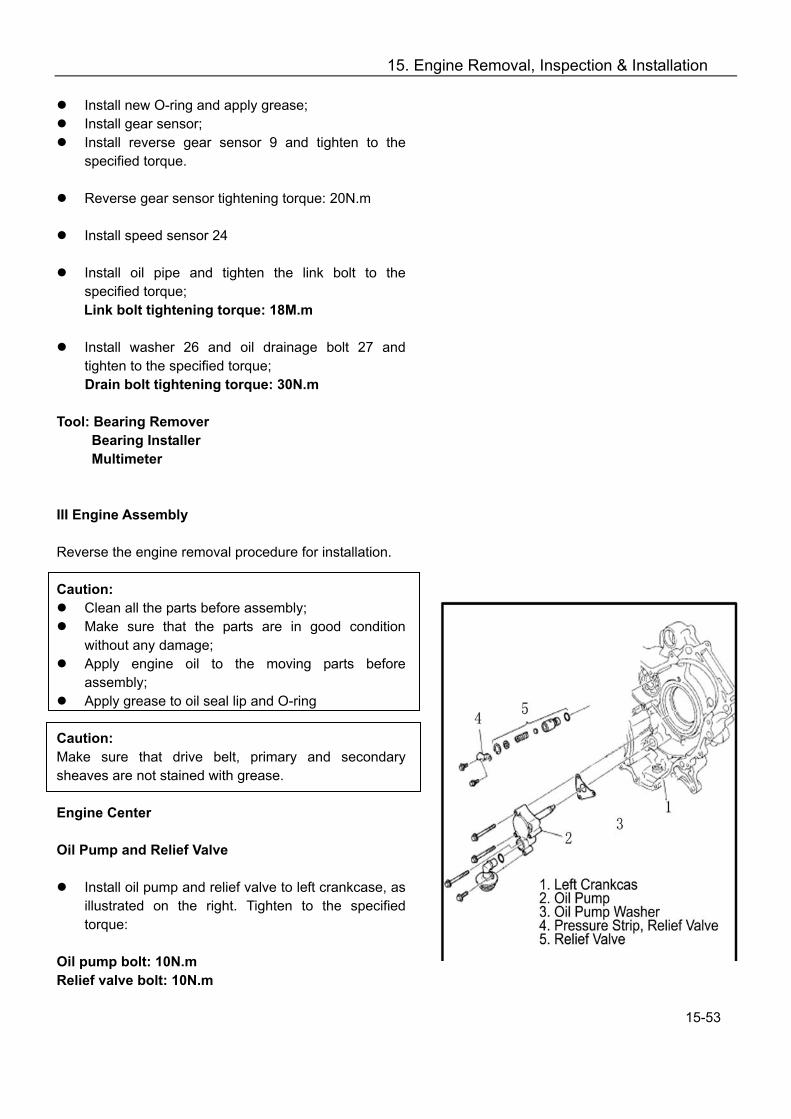
15. Engine Removal, Inspection & Installation
Install new O-ring and apply grease; Install gear sensor; Install reverse gear sensor 9 and tighten to the
specified torque.
Reverse gear sensor tightening torque: 20N.m
Install speed sensor 24
Install oil pipe and tighten the link bolt to the specified torque; Link bolt tightening torque: 18M.m
Install washer 26 and oil drainage bolt 27 and
tighten to the specified torque; Drain bolt tightening torque: 30N.m
Tool: Bearing Remover
Bearing Installer Multimeter
III Engine Assembly Reverse the engine removal procedure for installation. Caution:
Clean all the parts before assembly; Make sure that the parts are in good condition
without any damage; Apply engine oil to the moving parts before
assembly; Apply grease to oil seal lip and O-ring
Caution: Make sure that drive belt, primary and secondary sheaves are not stained with grease. Engine Center Oil Pump and Relief Valve
Install oil pump and relief valve to left crankcase, as illustrated on the right. Tighten to the specified torque:
Oil pump bolt: 10N.m Relief valve bolt: 10N.m
15-53
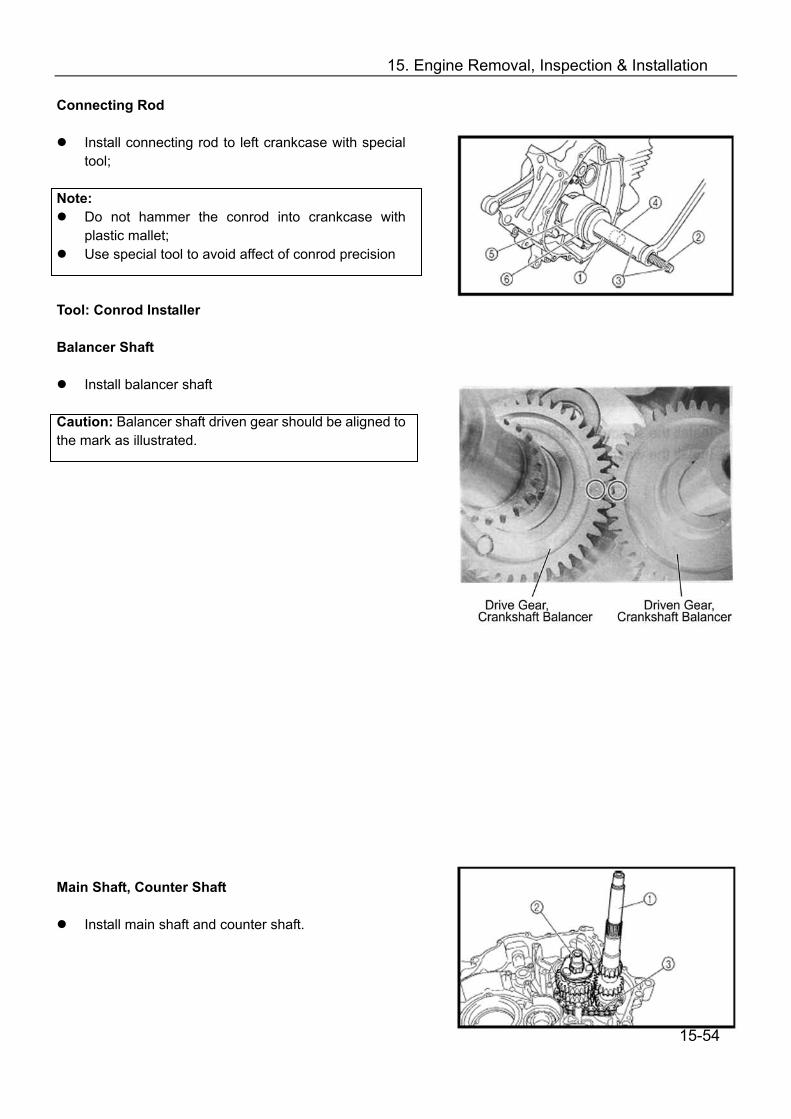
15. Engine Removal, Inspection & Installation
Connecting Rod
Install connecting rod to left crankcase with special tool;
Note:
Do not hammer the conrod into crankcase with plastic mallet;
Use special tool to avoid affect of conrod precision Tool: Conrod Installer Balancer Shaft
Install balancer shaft Caution: Balancer shaft driven gear should be aligned to the mark as illustrated. Main Shaft, Counter Shaft
Install main shaft and counter shaft.
15-54

15. Engine Removal, Inspection & Installation
Shift Cam, Shift For
Install shift can① and shift fork②
Check each part for smooth turning
Install low range driven gear to counter shaft③
Spray adequate engine oil to each part. Drive Bevel Gear
Install drive bevel gear and tighten to the specified torque.
Drive bevel gear tightening torque: 32N. m
Right Crankcase Driven Bevel Gear
Install driven bevel gear and tighten to the specified torque.
Driven bevel gear tightening torque: 25N. m
Check bevel gear backlash (Refer to 12-44)
Front Output Shaft
Install front output shaft to right crankcase
15-55

15. Engine Removal, Inspection & Installation
Apply sealant ①to the mating face of right crankcase.
Note: Apply sealant evenly in an uninterrupted thin line.
Install 2 dowel pins②
Assemble crankcase and tap slightly with a rubber hammer so that the crankcase is properly fitted.
Install bolt and tighten to the specified torque.
Crankcase bolt tightening torque: M6: 10N.m M8: 25N.M Note: Crankcase bolts should be tightened diagonally in several steps.
Place the steel ball and install gear positioning bolt and tighten the bolt to the specified torque.
Gear positioning bolt tightening torque: 18M.m
Engine Right Timing Chain
Put on timing chain 2 Clutch
Install clutch 1 and nut 2. Tighten the nut to the specified torque (left thread).
Clutch nut tightening torque: 70N.m
15-56
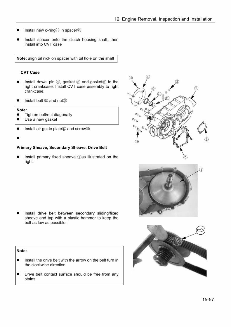
12. Engine Removal, Inspection and Installation
Install new o-ring in spacer⑥ ⑧
Install spacer onto the clutch housing shaft, then install into CVT case
Note: align oil nick on spacer with oil hole on the shaft
CVT Case
Install dowel pin ,④ gasket and gasket ② ⑤ to the right crankcase. Install CVT case assembly to right crankcase.
Install bolt and nut⑿ ③
Note:
Tighten bolt/nut diagonally Use a new gasket
Install air guide plate and scre⑩ w⑾
Primary Sheave, Secondary Sheave, Drive Belt
Install primary fixed sheave ①as illustrated on the right;
Install drive belt between secondary sliding/fixed sheave and tap with a plastic hammer to keep the belt as low as possible.
Note:
Install the drive belt with the arrow on the belt turn in the clockwise direction
Drive belt contact surface should be free from any
stains.
15-57

12. Engine Removal, Inspection and Installation
Install secondary sheave;
Install primary sliding sheave
Tighten primary sheave nut with special tool to the specified torque;
Primary sheave nut tightening torque: 115 N·m Tool: Rotor Holder Tighten secondary sheave nut with special tool to
the specified torque;
Secondary sheave tightening torque: 115 N·m Tool: Rotor Holder
Note: Turn the primary fixed sheave until the belt is seated in and both primary and secondary sheaves move together smoothly without slip. CVT Case Cover
Install the new gasket and dowel pins.
15-58
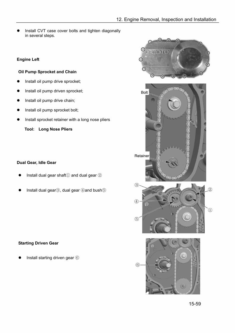
12. Engine Removal, Inspection and Installation
Install CVT case cover bolts and tighten diagonally in several steps.
Engine Left
Oil Pump Sprocket and Chain Install oil pump drive sprocket;
Install oil pump driven sprocket;
Install oil pump drive chain;
Install oil pump sprocket bolt;
Install sprocket retainer with a long nose pliers
Tool: Long Nose Pliers
Dual Gear, Idle Gear
Install dual gear shaft and ① dual gear ②
Install dual gear③, dual gear ④and bush⑤ Starting Driven Gear
Install starting driven gear ⑥
15-59

12. Engine Removal, Inspection and Installation
Install starting driven gear; Magneto Rotor
Install woodruff key into crankshaft groove;
Install magneto rotor 1; Note: Degrease the tapered part of rotor and crankshaft. Use nonflammable solvent to clean off the oily or greasy matter and fully dry the surfaces.
Left Crankcase Cover
Install dowel pin2 and gasket 3
Note: Use a new gasket
Apply Lubricant grease to oil sea lip;
Install left crankcase cover;
Install bolts; Recoil Starter
Install recoil starter 1
Install O-ring 2 Note: Use a new O-ring and apply lubricant grease to the O-ring
Install washer 3 and bolt 4, tighten to the specified torque:
Recoil starter bolt tightening torque: 55N.m
15-60
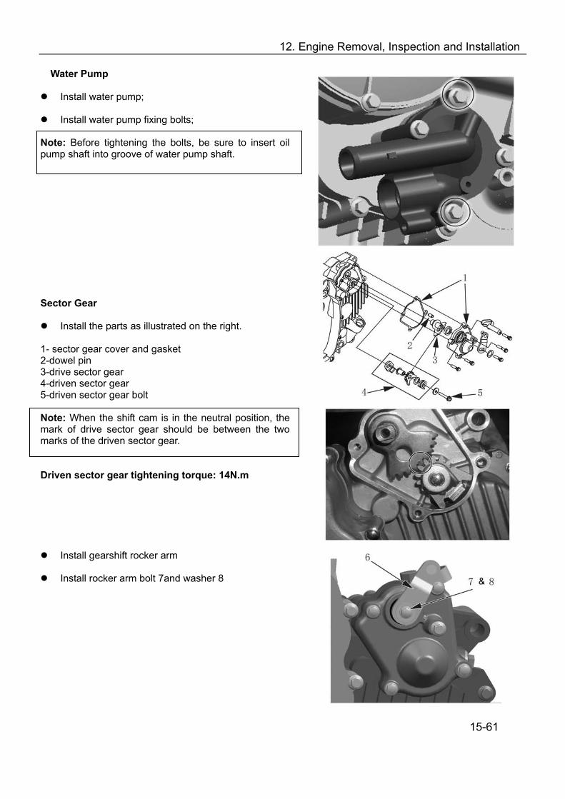
12. Engine Removal, Inspection and Installation
Water Pump
Install water pump;
Install water pump fixing bolts; Note: Before tightening the bolts, be sure to insert oil pump shaft into groove of water pump shaft.
Sector Gear
Install the parts as illustrated on the right. 1- sector gear cover and gasket 2-dowel pin 3-drive sector gear 4-driven sector gear 5-driven sector gear bolt Note: When the shift cam is in the neutral position, the mark of drive sector gear should be between the two marks of the driven sector gear.
Driven sector gear tightening torque: 14N.m
Install gearshift rocker arm
Install rocker arm bolt 7and washer 8
15-61
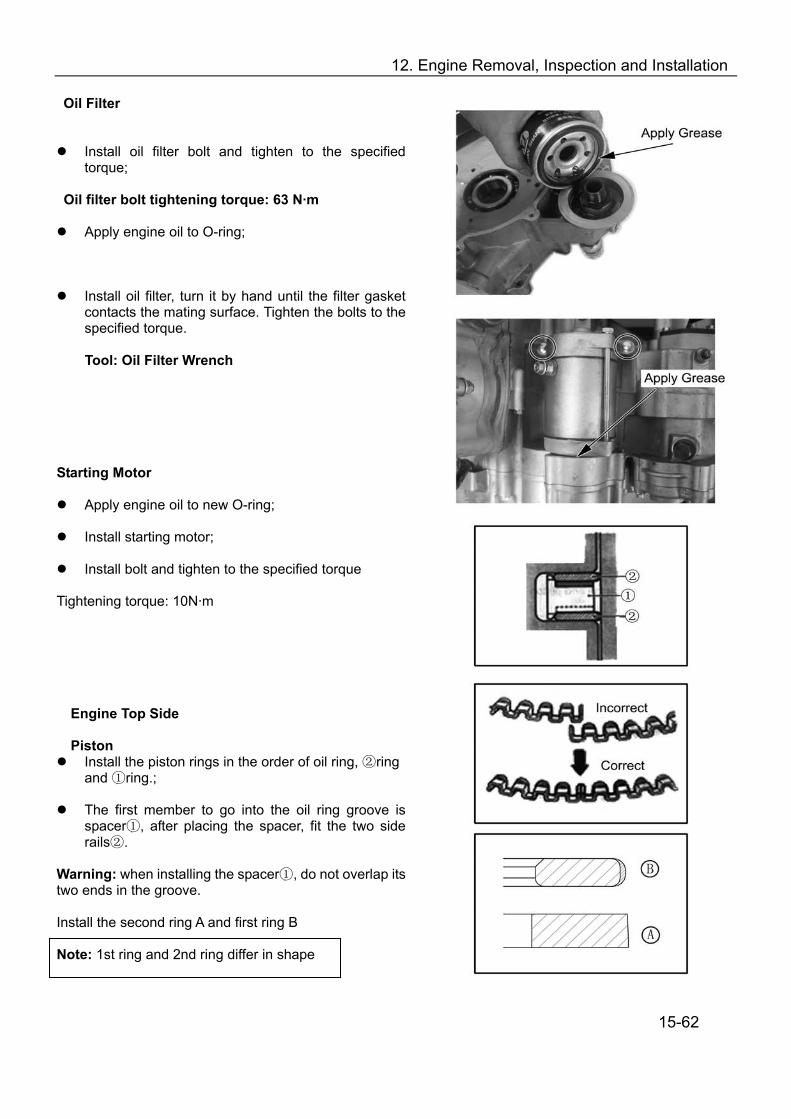
12. Engine Removal, Inspection and Installation
Oil Filter
Install oil filter bolt and tighten to the specified torque;
Oil filter bolt tightening torque: 63 N·m
Apply engine oil to O-ring;
Install oil filter, turn it by hand until the filter gasket contacts the mating surface. Tighten the bolts to the specified torque.
Tool: Oil Filter Wrench
Starting Motor
Apply engine oil to new O-ring;
Install starting motor;
Install bolt and tighten to the specified torque Tightening torque: 10N·m
Engine Top Side
Piston Install the piston rings in the order of oil ring, ring ②
and ring.;①
The first member to go into the oil ring groove is spacer , after placing the spacer, fit the two side ①rails . ②
Warning: when installing the spacer ,① do not overlap its two ends in the groove. Install the second ring A and first ring B Note: 1st ring and 2nd ring differ in shape
15-62
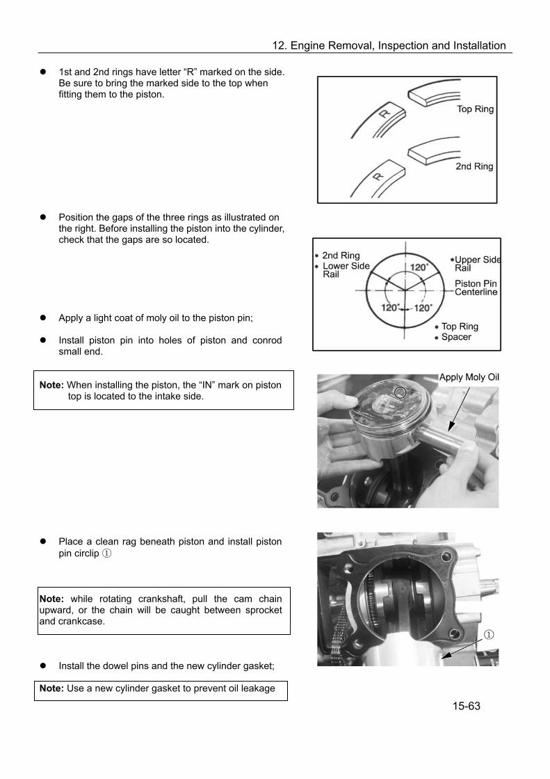
12. Engine Removal, Inspection and Installation
1st and 2nd rings have letter “R” marked on the side. Be sure to bring the marked side to the top when fitting them to the piston.
Position the gaps of the three rings as illustrated on the right. Before installing the piston into the cylinder, check that the gaps are so located.
Apply a light coat of moly oil to the piston pin;
Install piston pin into holes of piston and conrod small end.
Note: When installing the piston, the “IN” mark on piston
top is located to the intake side.
Place a clean rag beneath piston and install piston pin circlip ①
Note: while rotating crankshaft, pull the cam chain upward, or the chain will be caught between sprocket and crankcase.
Install the dowel pins and the new cylinder gasket; Note: Use a new cylinder gasket to prevent oil leakage
15-63

12. Engine Removal, Inspection and Installation
Cylinder
Apply engine oil to piston skirt and cylinder wall;
Hold each piston ring with proper position, insert piston into the cylinder;
Tighten the cylinder base bolts temporarily;
Note: When installing the cylinder and cylinder head, pull the cam chain upward, or the chain will be caught between sprocket and crankcase.
Install chain guide ;①
Fit the dowel pin and new cylinder cover gasket; Note: Use a new cylinder cover gasket to prevent oil leakage
Cylinder Head
Install the cylinder cover, tighten the cylinder head bolts diagonally to the specified torque.
Cylinder head bolt tightening torque: Initial: 25 N·m
Final: 38 N·m
Tighten the cylinder head nuts to the specified torque;
Cylinder head nuts tightening torque:
M6: 10 N·m M8: Initial 10 N·m
Final 25 N·m
Tighten the cylinder top nuts and cylinder base to the specified torque;
Tightening torque: 10 N·m
15-64
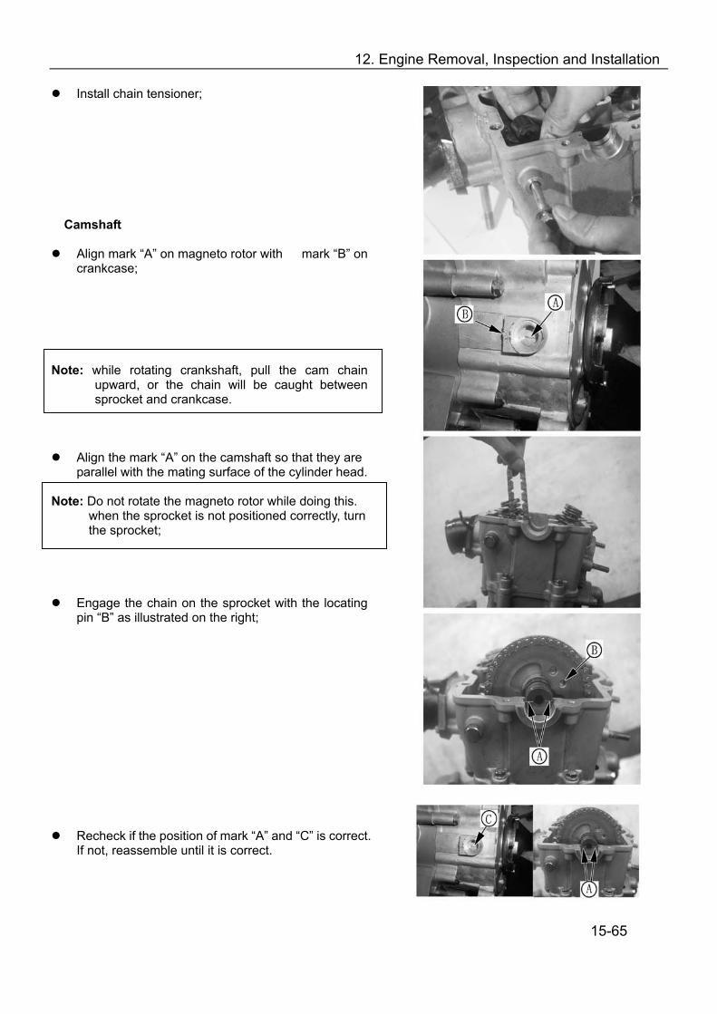
12. Engine Removal, Inspection and Installation
Install chain tensioner;
Camshaft
Align mark “A” on magneto rotor with mark “B” on crankcase;
Note: while rotating crankshaft, pull the cam chain
upward, or the chain will be caught between sprocket and crankcase.
Align the mark “A” on the camshaft so that they are parallel with the mating surface of the cylinder head.
Note: Do not rotate the magneto rotor while doing this.
when the sprocket is not positioned correctly, turn the sprocket;
Engage the chain on the sprocket with the locating pin “B” as illustrated on the right;
Recheck if the position of mark “A” and “C” is correct. If not, reassemble until it is correct.
15-65

12. Engine Removal, Inspection and Installation
Install crankshaft C-ring ①
Install lock washer so that it covers the locating pin;
Apply thread locker to the bolts before installing, and tighten them to the specified torque;
Sprocket bolt tightening torque: 15 N·m
Bend up the lock washer to lock the bolts.
Cylinder Head Cover
Clean the mating surface of cylinder head and cylinder head cover;
Install dowel pin to the cylinder head
Apply sealant to the mating surface of the cylinder
head cover;
Install cylinder head cover bolts, tighten diagonally to the specified torque.
Cylinder head cover bolt tightening torque: 10 N·m
Note: When tightening the cylinder head cover bolts, the piston must be at top dead center on the
compression stroke.
15-66
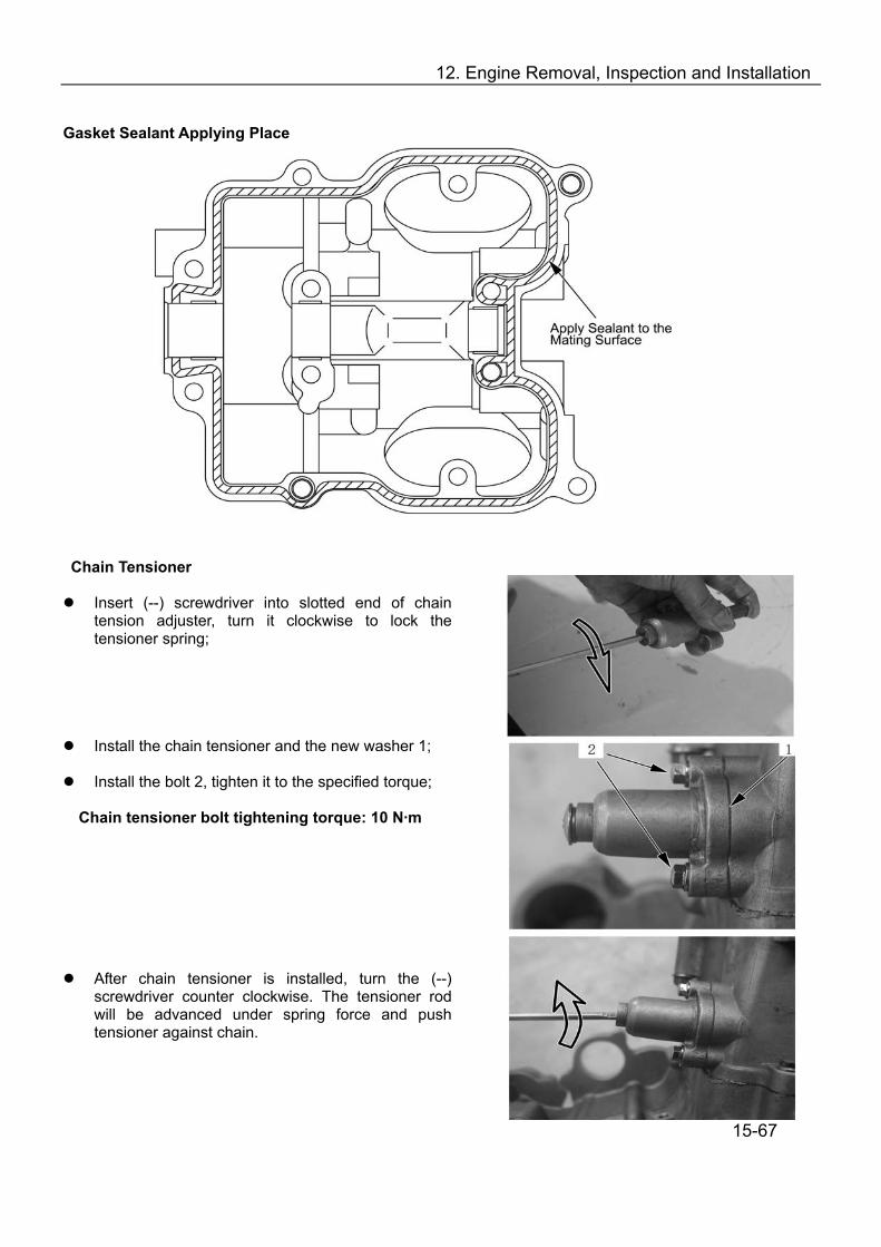
12. Engine Removal, Inspection and Installation
Gasket Sealant Applying Place
Chain Tensioner
Insert (--) screwdriver into slotted end of chain tension adjuster, turn it clockwise to lock the tensioner spring;
Install the chain tensioner and the new washer 1;
Install the bolt 2, tighten it to the specified torque; Chain tensioner bolt tightening torque: 10 N·m
After chain tensioner is installed, turn the (--) screwdriver counter clockwise. The tensioner rod will be advanced under spring force and push tensioner against chain.
15-67

12. Engine Removal, Inspection and Installation
Install the new gasket 3;
Install chain tensioner screw, tighten it to the
specifiedTorque Chain tensioner screw tightening torque: 8 N·m Valve Adjuster Cover
Refer to 11-3 for valve clearance; Use new rubber gasket and apply grease;
Install Valve Inspection Cap
Install valve inspection cap bolt; Spark Plug
Install spark plug with special tool and tighten to the specified torque;
Note: To avoid damage to the cylinder head thread,
screw in the spark plug with hand first, then tighten it to the specified torque with spark plug wrench.
Spark plug tightening torque: 18N.m Tool: Spark Plug Wrench Engine Periphery
Recoil Starter
Install recoil starter
Apply thread locker to the bolts and then tighten; Valve Inspection Cap
Install valve inspection cap
15-68
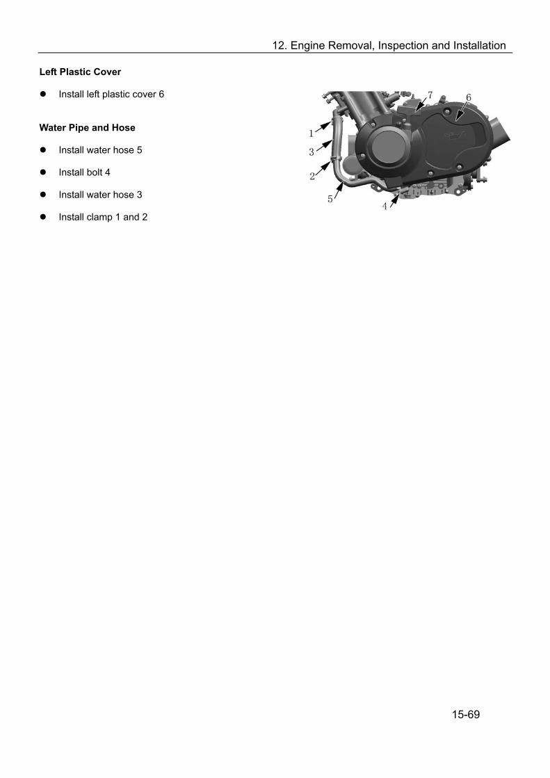
12. Engine Removal, Inspection and Installation
Left Plastic Cover
Install left plastic cover 6 Water Pipe and Hose
Install water hose 5
Install bolt 4
Install water hose 3
Install clamp 1 and 2
15-69
16. Carburetor
Carburetor Removal…………………………………………………….…16-2 Inspection……………………………………………………………..….…16-3 . Measurement and Adjustment…………………………………….………16-4 Carburetor Assembly………………………………………………………16-5 Carburetor Installation………………………………….……………….…16-6 Carburetor Parameters…………………… ……...…16-6 16-1

16. Carburetor
1. Carburetor Removal
Disassemble the carburetor in the following serial number: Serial No. Description Qty. Serial No. Description Qty.
1 Idle Adjust Shaft 1 10 Drain Screw 1 2 Vacuum Chamber Cover 1 11 Float Chamber 1 3 Spring 1 12 Float 1 4 Jet Needle Holder 1 13 Needle Valve Set 1 5 Spring 1 14 Main Jet (MJ) 1 6 Jet Needle Set 1 15 Needle Jet (NJ) 1 7 Vacuum Diaphragm 1 16 Pilot Jet (PJ) 1 8 Piston Valve 1 17 Starter Jet (GS) 1 9 Enriching Diaphragm 1 18 Pilot Air Jet (PAJ) 1
16-2

16. Carburetor
2. Inspection
Check carburetor body for cracks or damage.
Cracks or damage:→ Replace
Check carburetor float chamber, fuel passage for dirt or clog. Clean these parts.
Check float①, float tang ② for damage.
Damage: → Replace
Check valve seat①, needle valve②, O-ring③ for damage, abnormal wear or dirt.
Damage or wear or dirty: → Replace
Note: Valve set①, needle valve② should be replaced as
a set.
Check piston valve① for scratches, abnormal wear or damage.
Scratches, wear or damage: → Replace
Check diaphragm② for tears.
Tears: → Replace
Check vacuum chamber cover①, spring② for damage or cracks.
Damage or cracks: → Replace
16-3

16. Carburetor
Check the diaphragm for tears① ;
Tears: → Replace
Check the spring ②,cover for damage and tears③ ;
Damage or tears: → Replace
Check the jet needle , mail jet , needle jet , pilot ① ② ③air jet , pilot jet , starter jet and starter ④ ⑤ ⑥ plunger ⑦for wear and bends;
Wear or bends: → Replace
Check above jets for clog. Blow out the jets with compressed air.
Insert piston valve into carburetor body and check the free movement;
Check free movement of throttle valve. Replace with a new one if it’s stuck;
3. Measurement and Adjustment
Keep the carburetor in a upside down position. Measure distance “a” from the mating surface of float chamber (without gasket) to the top of float.
Note: The float arm should rest on the needle valve. Do not compress the needle valve.
Float Height: 10±1mm
16-4
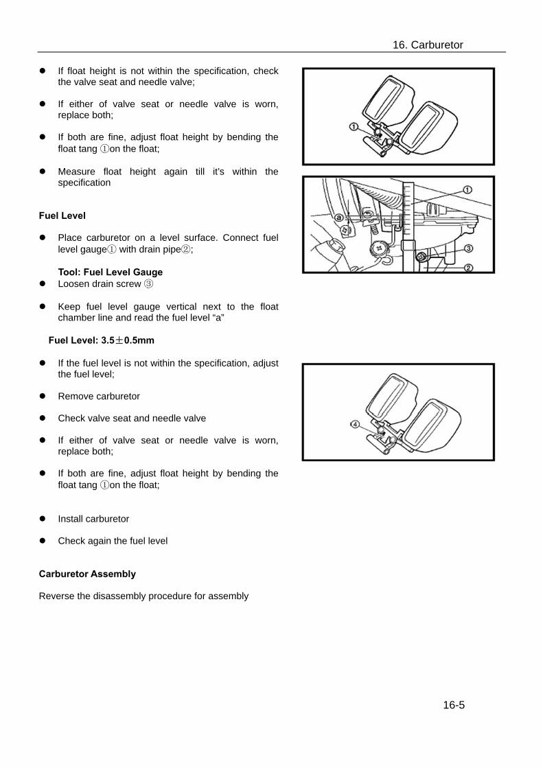
16. Carburetor
If float height is not within the specification, check the valve seat and needle valve;
If either of valve seat or needle valve is worn,
replace both;
If both are fine, adjust float height by bending the float tang ①on the float;
Measure float height again till it’s within the
specification Fuel Level
Place carburetor on a level surface. Connect fuel level gauge① with drain pipe②;
Tool: Fuel Level Gauge
Loosen drain screw ③
Keep fuel level gauge vertical next to the float chamber line and read the fuel level “a”
Fuel Level: 3.5±0.5mm
If the fuel level is not within the specification, adjust the fuel level;
Remove carburetor
Check valve seat and needle valve
If either of valve seat or needle valve is worn,
replace both;
If both are fine, adjust float height by bending the float tang ①on the float;
Install carburetor
Check again the fuel level Carburetor Assembly Reverse the disassembly procedure for assembly
16-5

16. Carburetor
Carburetor Installation ①-vacuum breather hose ②-starter cable ③-carburetor joint (engine intake manifold)) ④-throttle valve cover ⑤-throttle cable ⑥-Carburetor joint (air filter) ⑦-carburetor ⑧-drain hose ⑨-fuel inlet hose
Note: Align the installation mark of carburetor and carburetor joint 6. Carburetor Parameters Type Aperture No. Throat size (mm) Pilot (r/min) Float height (mm) Fuel level (mm) Main jet (MJ) Main air jet (MAJ) Jet needle (JN) Needle jet (NJ) Pilot jet (PJ) Pilot screw (PS) Pilot air jet1 (PAJ1) Pilot air jet2 (PAJ2)
MIKUNI BSR36-89 07G0 36mm 1300 r/min±100 r/min 10±1 3.5±0.5 N102221-130# MD13/24-35# J8-5E26 785-401011-P-OM N224103-22.5# 604-16013-1A MD13/24-65# N211100-165# 16-6
17. Cooling and Lubrication System
Cooling System Illustration…………………………………………17-2 Engine Coolant………………………………………………………17-3 Inspection of Cooling Circuit……………………….………………17-3 Inspection and Cleaning of Radiator and Water Hoses…………17-4 Inspection of Fan Motor……………………………………….……17-5 Inspection of Water Temperature Sensor…………………………17-6 Inspection of Thermostat……………………………………………17-6 Water Pump……………………………………………………….…17-7
Water Pump Removal and Disassembly……………………17-7 Inspection………………………………………………………17-9 Water Pump Assembly and Installation………..……………17-10
Lubrication System Illustration………………………………..……17-14 Inspection of Lubrication System……………………….…………17-15 Inspection of Oil Pump and Relief Valve……………………….…17-15
17-1
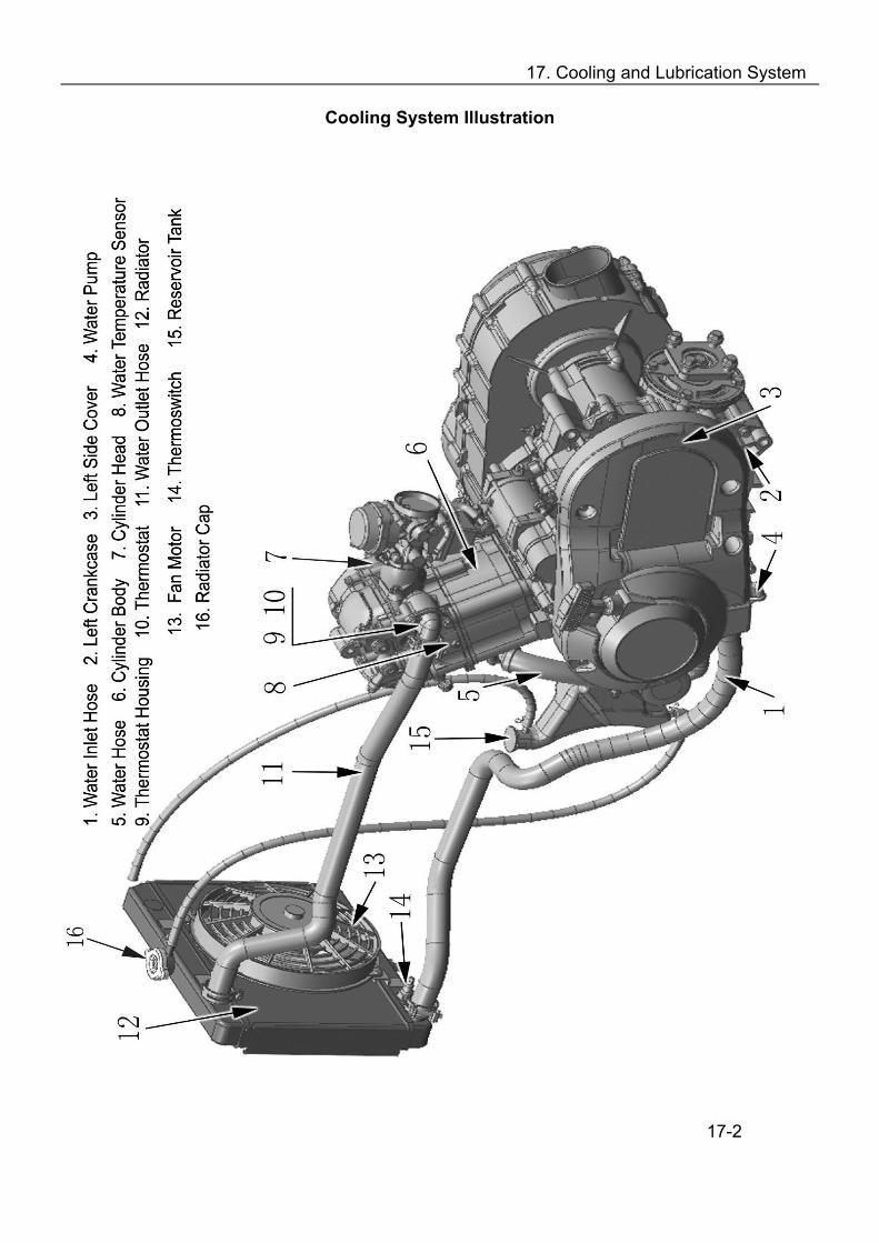
17. Cooling and Lubrication System
Cooling System Illustration
17-2
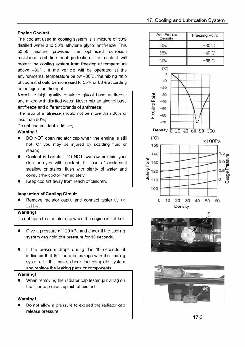
17. Cooling and Lubrication System
Engine Coolant The coolant used in cooling system is a mixture of 50% distilled water and 50% ethylene glycol antifreeze. This 50:50 mixture provides the optimized corrosion resistance and fine heat protection. The coolant will protect the cooling system from freezing at temperature above –30. If the vehicle will be operated at the environmental temperature below –30, the mixing ratio of coolant should be increased to 55% or 60% according to the figure on the right. Note:Use high quality ethylene glycol base antifreeze and mixed with distilled water. Never mix an alcohol base antifreeze and different brands of antifreeze; The ratio of antifreeze should not be more than 60% or less than 50%; Do not use anti-leak additive; Warning !
DO NOT open radiator cap when the engine is still hot. Or you may be injured by scalding fluid or steam;
Coolant is harmful. DO NOT swallow or stain your skin or eyes with coolant. In case of accidental swallow or stains, flush with plenty of water and consult the doctor immediately.
Keep coolant away from reach of children. Inspection of Cooling Circuit
Remove radiator cap① and connect tester ② to
filler. Warning! Do not open the radiator cap when the engine is still hot.
Give a pressure of 120 kPa and check if the cooling system can hold this pressure for 10 seconds.
If the pressure drops during this 10 seconds, it
indicates that the there is leakage with the cooling system. In this case, check the complete system and replace the leaking parts or components.
Warning! When removing the radiator cap tester, put a rag on
the filler to prevent splash of coolant. Warning!
Do not allow a pressure to exceed the radiator cap release pressure.
17-3

17. Cooling and Lubrication System
Inspection and Cleaning of Radiator and Water Hoses Radiator Cap
Remove radiator cap① Install radiator cap to cap tester②
Slowly increase pressure to 93.3-122.7 kPa and
check if the cap can hold the pressure for at least 10 seconds.
If the cap cannot meet the pressure requirement,
replace it. Radiator Cap Valve Opening Pressure: Standard: 93.9-122.9 kPa Tool: Radiator Cap Tester Radiator Inspection and Cleaning
Remove dirt or trash from radiator with compressed air;
Correct the radiator fins with a small screwdriver;
Radiator Hose Inspection
Check radiator hoses for leakage or damage.
Leakage or Damage: → Replace
Check tightening of clamps. Replace the clamps if necessary;
After inspection and cleaning of radiator and hoses, check coolant level. Fill coolant if necessary.
17-4

17. Cooling and Lubrication System
Inspection of Fan Motor
Remove fan motor from radiator
Turn the vanes and check if they can turn smoothly;
Check fan motor: Make sure that the battery applies 12 volts to the motor and the motor will run at full speed while the ammeter shall indicate the ampere not more than 5A.
If the motor does not run or the ampere exceeds the limit, replace the motor.
Installation: Apply a little thread locker to the bolts
and tighten to the specified torque.
Fan Motor Bolt Tightening Torque: 10N.m Inspection of Thermoswitch
Remove thermoswitch Check the thermoswitch for closing or opening by
testing it at the bench as illustrated. Connect the thermoswitch① to the circuit tester, place it in a vessel with engine oil. Place the vessel above a stove.
Heat the oil to raise the temperature slowly and take the reading from thermometer ② when the thermoswitch closes and opens.
Tool: ammeter Thermoswitch Operating Temperature Standard: (OFF-ON): Approx. 88 (ON-OFF): Approx. 82 Note:
Avoid sharp impact on thermoswitch. Avoid contact of thermoswitch with thermometer or
vessel Installation: Use a new O-ring③ and tighten the
thermoswitch to the specified torque:
Thermoswitch Tightening Torque: 17N.m
Check coolant level after installation of thermoswitch. Fill coolant if necessary.
17-5
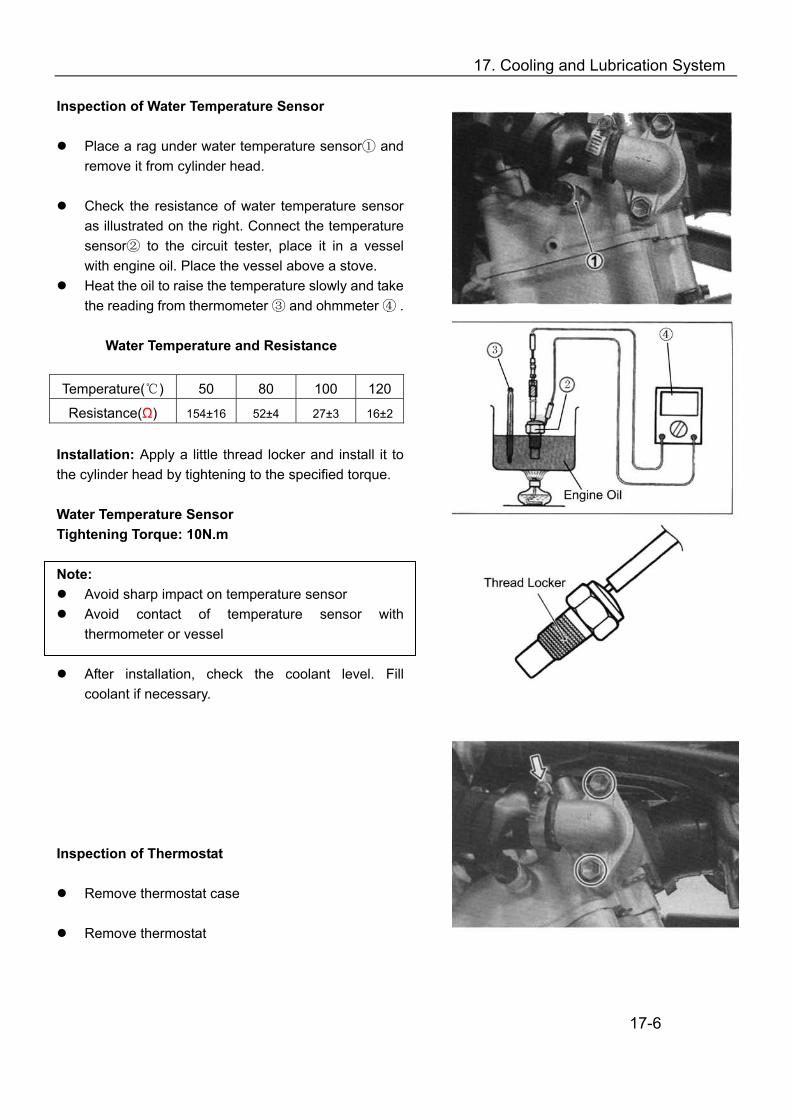
17. Cooling and Lubrication System
Inspection of Water Temperature Sensor
Place a rag under water temperature sensor① and remove it from cylinder head.
Check the resistance of water temperature sensor
as illustrated on the right. Connect the temperature sensor② to the circuit tester, place it in a vessel with engine oil. Place the vessel above a stove.
Heat the oil to raise the temperature slowly and take the reading from thermometer ③ and ohmmeter ④ .
Water Temperature and Resistance
Temperature( ) 50 80 100 120
Resistance(Ω) 154±16 52±4 27±3 16±2
Installation: Apply a little thread locker and install it to the cylinder head by tightening to the specified torque. Water Temperature Sensor Tightening Torque: 10N.m Note:
Avoid sharp impact on temperature sensor Avoid contact of temperature sensor with
thermometer or vessel
After installation, check the coolant level. Fill coolant if necessary.
Inspection of Thermostat
Remove thermostat case
Remove thermostat
17-6
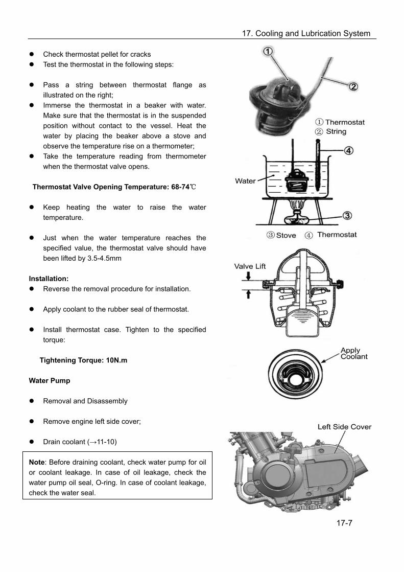
17. Cooling and Lubrication System
Check thermostat pellet for cracks Test the thermostat in the following steps:
Pass a string between thermostat flange as
illustrated on the right; Immerse the thermostat in a beaker with water.
Make sure that the thermostat is in the suspended position without contact to the vessel. Heat the water by placing the beaker above a stove and observe the temperature rise on a thermometer;
Take the temperature reading from thermometer when the thermostat valve opens.
Thermostat Valve Opening Temperature: 68-74
Keep heating the water to raise the water temperature.
Just when the water temperature reaches the
specified value, the thermostat valve should have been lifted by 3.5-4.5mm
Installation:
Reverse the removal procedure for installation.
Apply coolant to the rubber seal of thermostat.
Install thermostat case. Tighten to the specified torque:
Tightening Torque: 10N.m
Water Pump
Removal and Disassembly
Remove engine left side cover;
Drain coolant (→11-10) Note: Before draining coolant, check water pump for oil or coolant leakage. In case of oil leakage, check the water pump oil seal, O-ring. In case of coolant leakage, check the water seal.
17-7

17. Cooling and Lubrication System
Remove clamps and water hoses
Release bolts and remove water pump
Remove O-ring Note: Do not reuse the O-ring.
Remove the overflow tube
Release water pump cover screws, water pump cover and gasket
Remove E-ring and impeller
Remove seal ring ①and rubber seal②
17-8

17. Cooling and Lubrication System
Remove mechanical seal with special tool Note: The mechanical seal does not need to be removed if there is no abnormal condition. Note: Do not reuse a removed mechanical seal
Put a rag on the water pump body
Remove oil seal. Note: The oil seal does not need to be removed if there is no abnormal condition Note: Do not reuse a removed oil seal
Remove bearing with special tool. Note: The bearing does not need to be removed if there is no abnormal noise. Note: Do not reuse a removed bearing. Inspection of Water Pump Bearing
Check the play of bearing by hand while it is still in the water pump body;
Turn inner race of bearing to check for abnormal noise and smooth rotation;
Replace the bearing if there is abnormal condition; Mechanical Seal
Check mechanical seal for damage, pay special attention to the seal face;
In case of leakage or damage, replace the mechanical seal. If necessary, also replace the seal ring.
17-9

17. Cooling and Lubrication System
Oil Seal
Check oil seal for damage. Pay special attention to the oil seal lip;
In case of damage or leakage, replace the oil seal;
Water Pump Body
Check the mating mace of water pump body with bearing and mechanical seal. Damage: →Replace
Impeller
Check the impeller and shaft for damage. Damage: →Replace
Assembly and Installation of Water Pump
Install oil seal with special tool; Tool: Oil Seal Installer Note: The stamped mark on the oil seal faces outside
Apply a little grease to the oil seal lip.
17-10
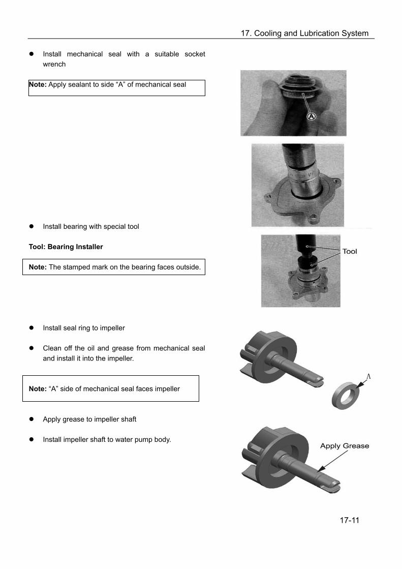
17. Cooling and Lubrication System
Install mechanical seal with a suitable socket wrench
Note: Apply sealant to side “A” of mechanical seal
Install bearing with special tool Tool: Bearing Installer Note: The stamped mark on the bearing faces outside.
Install seal ring to impeller
Clean off the oil and grease from mechanical seal and install it into the impeller.
Note: “A” side of mechanical seal faces impeller
Apply grease to impeller shaft
Install impeller shaft to water pump body.
17-11

17. Cooling and Lubrication System
Install E-ring to water pump shaft;
Install new gasket to water pump body;
Install water pump cover and tighten the bolts and bleed bolt.
Water Pump Cover Bolts Tightening Torque: 6N.m
Check impeller for smooth turning.
Install the new O-ring Note:
Use the new O-ring to prevent oil leakage; Apply grease to O-ring
17-12
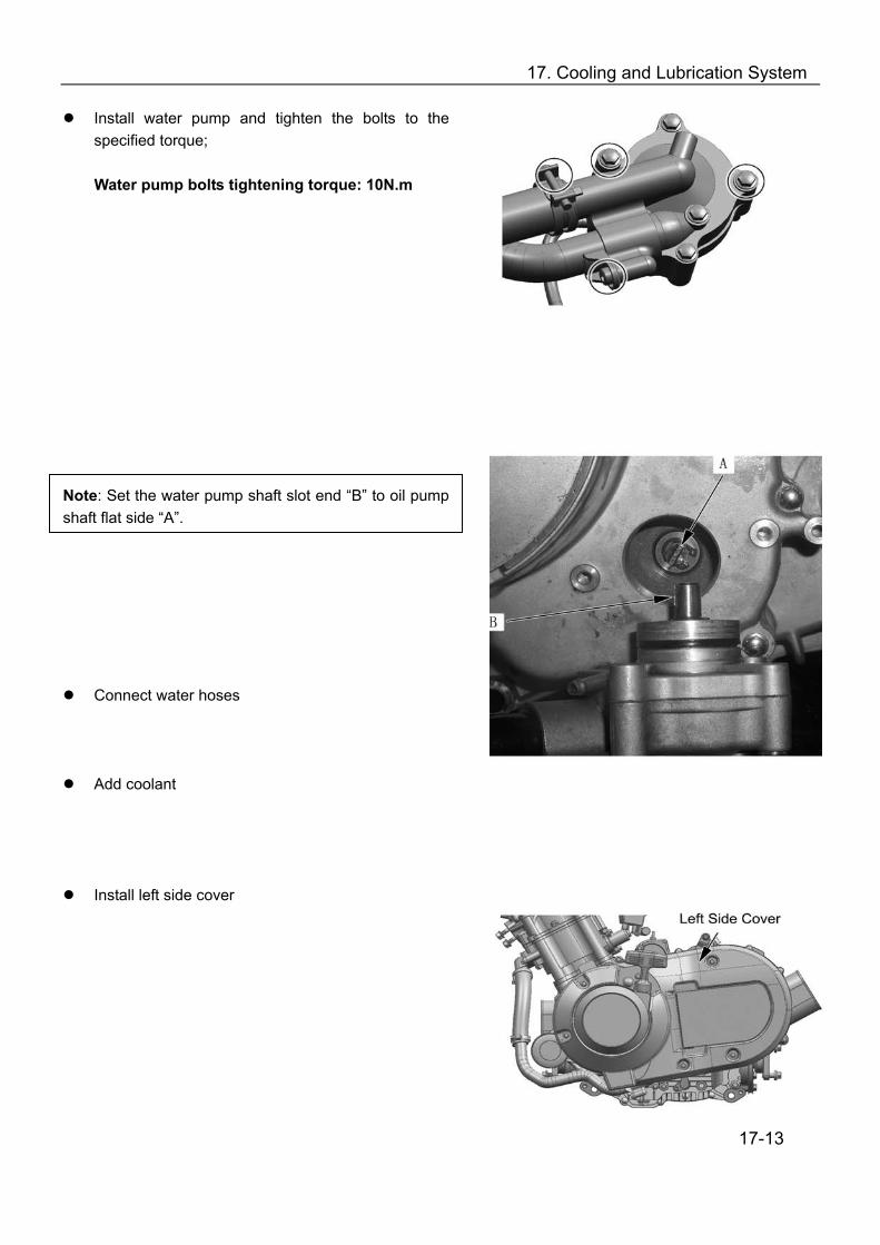
17. Cooling and Lubrication System
Install water pump and tighten the bolts to the specified torque;
Water pump bolts tightening torque: 10N.m
Note: Set the water pump shaft slot end “B” to oil pump shaft flat side “A”.
Connect water hoses
Add coolant
Install left side cover
17-13
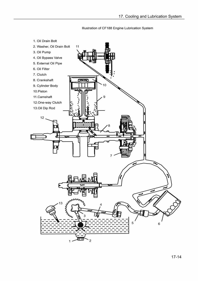
17. Cooling and Lubrication System
17-14
17. Cooling and Lubrication System
Inspection of Lubrication System (→11-8) Inspection of Oil Pump and Relief Valve(→12-41) 17-15

18. Electrical System
Charging System……………..18-1 Electric Starting…………..…..18-3 Ignition System…………….…18-5
18-1

18. Electrical System
Charging System
Resistance of Generator Coil
Measure resistance between the three lead wires; Replace a new stator coil if resistance not within
specified value, Check that the generator core is insulated.
Set multimeter at 1×10Ω
Generator Coil Resistance : 0.9-1.5Ω(Yellow-Yellow) Insulate Resistance: ∞Ω(Yellow-Earthing wire) Generator Non-load Performance
Start engine run it at 5000r/min Measure AC voltage between three lead wires of
generator with multimeter. Replace the generator if the voltage is lower than
the specified value. Set Multimeter to AC Position Generator Non-load Performance: ﹥200V (AC) at 5000r/min
18-2
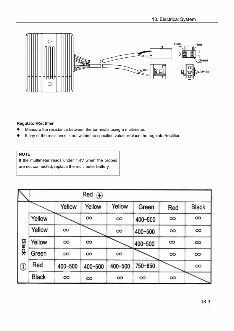
18. Electrical System
Regulator/Rectifier
Measure the resistance between the terminals using a multimeter. If any of the resistance is not within the specified value, replace the regulator/rectifier.
.
NOTE: If the multimeter reads under 1.4V when the probes are not connected, replace the multimeter battery.
18-3
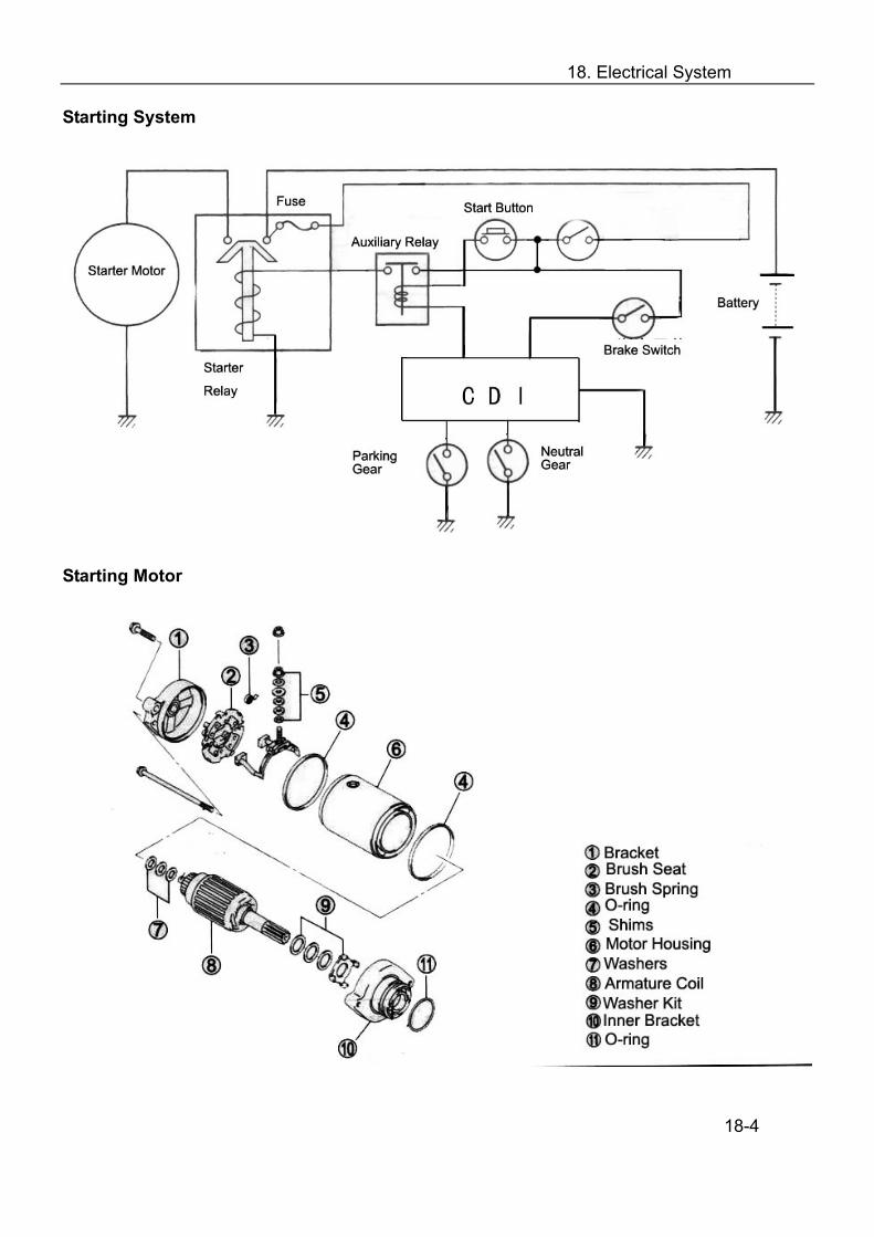
18. Electrical System
Starting System
Starting Motor
18-4
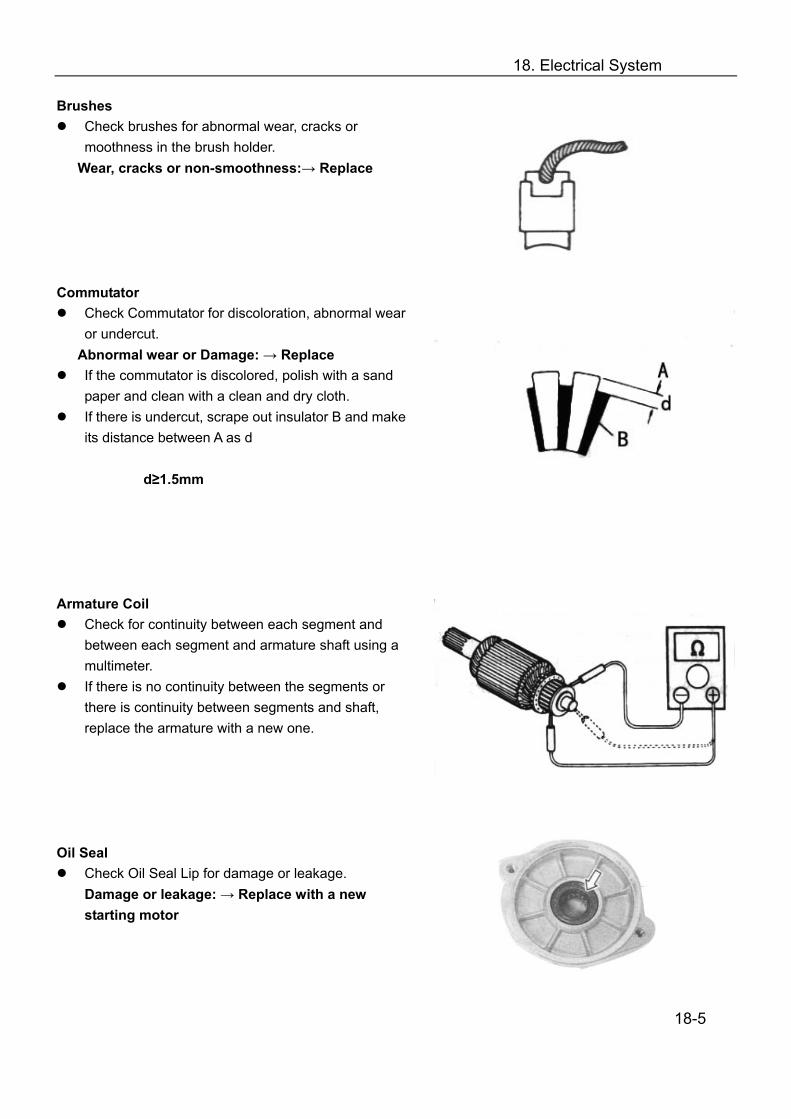
18. Electrical System
Brushes Check brushes for abnormal wear, cracks or
moothness in the brush holder. Wear, cracks or non-smoothness:→ Replace
Commutator
Check Commutator for discoloration, abnormal wear or undercut.
Abnormal wear or Damage: → Replace If the commutator is discolored, polish with a sand
paper and clean with a clean and dry cloth. If there is undercut, scrape out insulator B and make
its distance between A as d
d≥1.5mm Armature Coil
Check for continuity between each segment and between each segment and armature shaft using a multimeter.
If there is no continuity between the segments or there is continuity between segments and shaft, replace the armature with a new one.
Oil Seal
Check Oil Seal Lip for damage or leakage. Damage or leakage: → Replace with a new starting motor
18-5

18. Electrical System
Starter Relay
Apply 12V to the terminals and check for continuity between the positive and negative terminals using a multimeter.
If the starter relay clicks and continuity is found, the starter relay is OK.
If there is no continuity when without the 12V, the relay is OK.
Note: Do not apply the battery voltage to the starter relay for more than 2 seconds. This may cause overheat and damage the relay coil.
Measure the coil resistance between the terminals using a multimeter. If the resistance is out of the specified value, replace the starter relay with a new one.
Set multimeter to 1x10Ω position
Starter relay coil resistance: 3-5Ω
Auxiliary Starter Relay
Apply 12V to starter relay positive and negative terminals and check for continuity between A and B using a multimeter.
If the starter relay clicks and continuity is found, the starter relay is OK.
If there is no continuity when without the 12V, the relay is OK.
Set multimeter to 1x100Ω position
Auxiliary starter relay coil resistance: 90-100Ω
18-6
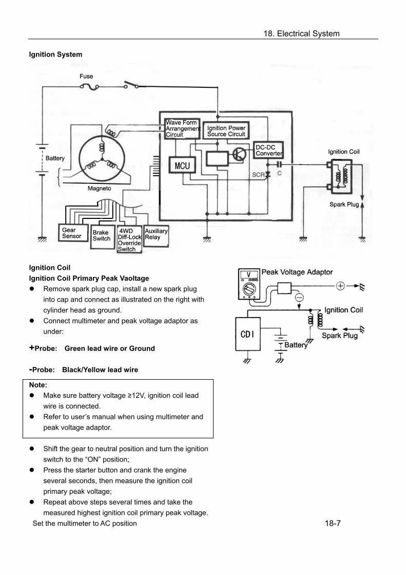
18. Electrical System
Ignition System
Ignition Coil Ignition Coil Primary Peak Vaoltage
Remove spark plug cap, install a new spark plug into cap and connect as illustrated on the right with cylinder head as ground.
Connect multimeter and peak voltage adaptor as under:
+Probe: Green lead wire or Ground
-Probe: Black/Yellow lead wire
Note: Make sure battery voltage ≥12V, ignition coil lead
wire is connected. Refer to user’s manual when using multimeter and
peak voltage adaptor.
Shift the gear to neutral position and turn the ignition switch to the “ON” position;
Press the starter button and crank the engine several seconds, then measure the ignition coil primary peak voltage;
Repeat above steps several times and take the measured highest ignition coil primary peak voltage.
Set the multimeter to AC position
18-7
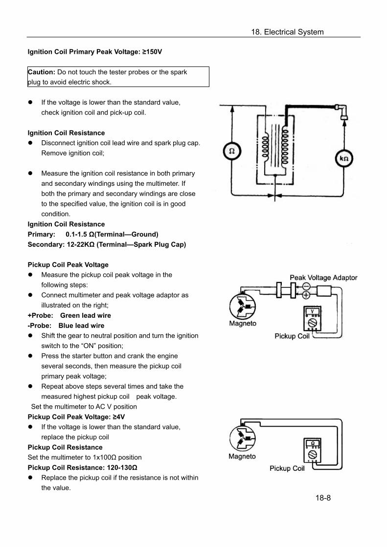
18. Electrical System
Ignition Coil Primary Peak Voltage: ≥150V Caution: Do not touch the tester probes or the spark plug to avoid electric shock.
If the voltage is lower than the standard value, check ignition coil and pick-up coil.
Ignition Coil Resistance
Disconnect ignition coil lead wire and spark plug cap. Remove ignition coil;
Measure the ignition coil resistance in both primary
and secondary windings using the multimeter. If both the primary and secondary windings are close to the specified value, the ignition coil is in good condition.
Ignition Coil Resistance Primary: 0.1-1.5 Ω(Terminal—Ground) Secondary: 12-22KΩ (Terminal—Spark Plug Cap) Pickup Coil Peak Voltage
Measure the pickup coil peak voltage in the following steps:
Connect multimeter and peak voltage adaptor as illustrated on the right;
+Probe: Green lead wire -Probe: Blue lead wire
Shift the gear to neutral position and turn the ignition switch to the “ON” position;
Press the starter button and crank the engine several seconds, then measure the pickup coil primary peak voltage;
Repeat above steps several times and take the measured highest pickup coil peak voltage.
Set the multimeter to AC V position Pickup Coil Peak Voltage: ≥4V
If the voltage is lower than the standard value, replace the pickup coil
Pickup Coil Resistance Set the multimeter to 1x100Ω position Pickup Coil Resistance: 120-130Ω
Replace the pickup coil if the resistance is not within the value.
18-8

19. Troubleshooting
1. Engine Complaint Symptom and Possible Causes Remedy
Engine will not start of is hard to start
Compression is Too Low 1. Worn cylinder 2. Worn piston ring 3. Leakage with cylinder gasket
Wear valve guide or improper valve seating
4. Loose spark plug 5. Slow cranking of starting motor 6. Faulty valve timing 7. Improper valve clearance
No Sparking from Spark Plug 1. Fouled spark plug 2. Wet spark plug 3. Defective ignition coil 4. Open or short circuit with pickup coil 5. Faulty generator 6. Faulty CDI No Fuel Reach Into Carburetor 1. Clogged fuel tank vent tube 2. Clogged or faulty fuel valve 3. Faulty carburetor needle valve 4. Clogged fuel hose 5. Clogged fuel filter
Transfer is not in Neutral position
Replace Replace Replace Repair or Replace
Tighten Check electrical part Adjust Adjust
Clean or Replace Clean and dry or replace Replace Replace Replace Replace
Clean or Replace Clean or Replace Replace Replace Clean or Replace Set to Neutral position
Engine stalls easily or has unstable idle speed
1. Improper valve clearance 2. Improper valve seating 3. Faulty valve guide 4. Worn rocker arm or rocker arm shaft 5. Fouled spark plug 6. Improper spark plug gap 7. Faulty ignition coil 8. Faulty CDI 9. Faulty generator 10. Improper fuel level in float chamber 11. Clogged carburetor jet 12. Faulty fuel valve 13. Improper adjustment or idle screw
Adjust Replace or Correct Replace Replace Replace Replace or Adjust Replace Replace Replace Adjust Fuel level Clean Replace Adjust
19-1
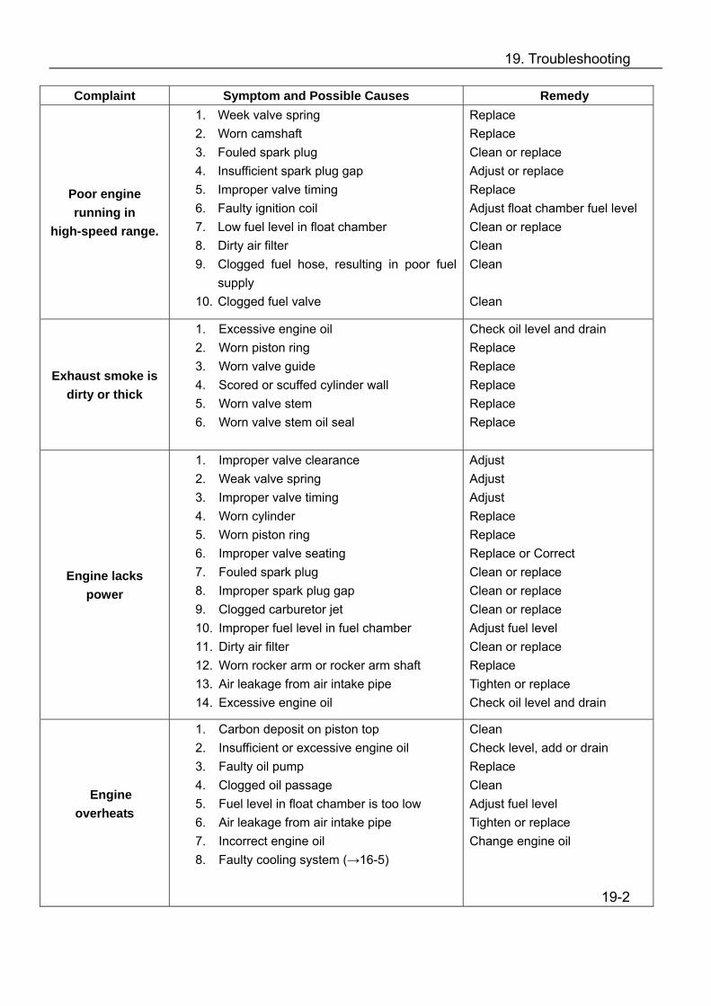
19. Troubleshooting
Complaint Symptom and Possible Causes Remedy
Poor engine running in
high-speed range.
1. Week valve spring 2. Worn camshaft 3. Fouled spark plug 4. Insufficient spark plug gap 5. Improper valve timing 6. Faulty ignition coil 7. Low fuel level in float chamber 8. Dirty air filter 9. Clogged fuel hose, resulting in poor fuel
supply 10. Clogged fuel valve
Replace Replace Clean or replace Adjust or replace Replace Adjust float chamber fuel level Clean or replace Clean Clean Clean
Exhaust smoke is dirty or thick
1. Excessive engine oil 2. Worn piston ring 3. Worn valve guide 4. Scored or scuffed cylinder wall 5. Worn valve stem 6. Worn valve stem oil seal
Check oil level and drain Replace Replace Replace Replace Replace
Engine lacks power
1. Improper valve clearance 2. Weak valve spring 3. Improper valve timing 4. Worn cylinder 5. Worn piston ring 6. Improper valve seating 7. Fouled spark plug 8. Improper spark plug gap 9. Clogged carburetor jet 10. Improper fuel level in fuel chamber 11. Dirty air filter 12. Worn rocker arm or rocker arm shaft 13. Air leakage from air intake pipe 14. Excessive engine oil
Adjust Adjust Adjust Replace Replace Replace or Correct Clean or replace Clean or replace Clean or replace Adjust fuel level Clean or replace Replace Tighten or replace Check oil level and drain
Engine overheats
1. Carbon deposit on piston top 2. Insufficient or excessive engine oil 3. Faulty oil pump 4. Clogged oil passage 5. Fuel level in float chamber is too low 6. Air leakage from air intake pipe 7. Incorrect engine oil 8. Faulty cooling system (→16-5)
Clean Check level, add or drain Replace Clean Adjust fuel level Tighten or replace Change engine oil 19-2

19. Troubleshooting
Complaint Symptom and Possible Causes Remedy
Valve Chatter 1. Excessive valve clearance 2. Worn or broken valve spring 3. Worn rocker arm or camshaft
Replace Replace Replace
Noise from Piston 1. Worn piston 2. Worn cylinder 3. Carbon deposit in combustion chamber 4. Worn piston pin or pin hole 5. Worn piston ring or piston ring groove
Replace Replace Clean Replace Replace
Noise from Timing chain 1. Stretched chain 2. Worn sprocket wheel 3. Faulty chain tensioner
Replace chain & sprocket Replace chain & sprocket Repair or replace
Noise from Clutch 1. Worn or damaged crankshaft spline 2. Worn inner race spline
Replace crankshaft Replace inner race
Noise from Crankshaft 1. Rattling bearing 2. Worn or burnt crank pin bearing 3. Excessive thrust clearance
Replace Replace Replace
Noise from CVT 1. Worn or slipping drive belt 2. Worn rollers in primary sheave
Replace Replace
Engine is noisy
Noise from Transmission 1. Worn or damaged gear 2. Worn or damaged input or output shafts 3. Worn bearing 4. Worn bushing
Replace Replace Replace Replace
Slipping Clutch
1. Worn or damaged clutch shoes 2. Weakened clutch shoe spring 3. Worn clutch housing 4. Worn or slipping drive belt
Replace Replace Replace REplace
19-3
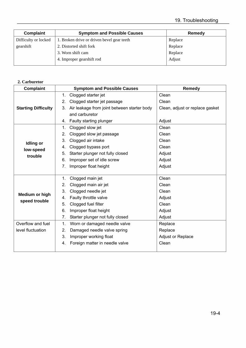
19. Troubleshooting
Complaint Symptom and Possible Causes Remedy Difficulty or locked gearshift
1. Broken drive or driven bevel gear teeth 2. Distorted shift fork 3. Worn shift cam 4. Improper gearshift rod
Replace Replace Replace Adjust
2. Carburetor
Complaint Symptom and Possible Causes Remedy
Starting Difficulty
1. Clogged starter jet 2. Clogged starter jet passage 3. Air leakage from joint between starter body
and carburetor 4. Faulty starting plunger
Clean Clean Clean, adjust or replace gasket Adjust
Idling or low-speed
trouble
1. Clogged slow jet 2. Clogged slow jet passage 3. Clogged air intake 4. Clogged bypass port 5. Starter plunger not fully closed 6. Improper set of idle screw 7. Improper float height
Clean Clean Clean Clean Adjust Adjust Adjust
Medium or high speed trouble
1. Clogged main jet 2. Clogged main air jet 3. Clogged needle jet 4. Faulty throttle valve 5. Clogged fuel filter 6. Improper float height 7. Starter plunger not fully closed
Clean Clean Clean Adjust Clean Adjust Adjust
Overflow and fuel level fluctuation
1. Worn or damaged needle valve 2. Damaged needle valve spring 3. Improper working float 4. Foreign matter in needle valve
Replace Replace Adjust or Replace Clean
19-4

19. Troubleshooting
3. Cooling System/Radiator Complaint Symptom and Possible Causes Remedy
Engine overheats
1. Clogged water passage or radiator 2. Air in the cooling system; insufficient
coolant 3. Faulty water pump 4. Incorrect coolant 5. Faulty thermostat 6. Faulty fan motor or thermoswitch
Clean Discharge air and add coolant Check and replace Replace Replace Check and/or replace
Engine coolant overcools
1. Faulty thermoswitch 2. Extremely cold weather 3. Faulty thermostat
Replace Put on radiator cover Replace
4. Ignition System
Complaint Symptom and Possible Causes Remedy
No Sparking or Weak Sparking
1. Faulty CDI 2. Faulty spark plug 3. Faulty Generator 4. Insufficient battery voltage 5. Faulty ignition coil 6. Faulty pickup coil
Check and replace Check and replace Check and replace Check and replace Check and replace Check and replace
19-5