centrifugal - fancoil | ventilclima · vce 10÷60 vce 70÷90 vce 100÷120* 10 20 30 40 50 60 70 80...
TRANSCRIPT
VCE
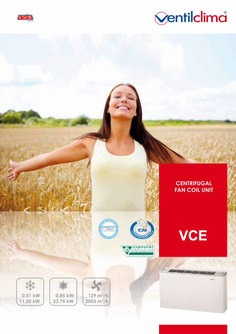
0,5111,00
0,8523,75
1292003
VCE
CENTRIFUGALFAN COIL UNIT
kWkW
kWkW
m3/hm3/h
3VERSION12 SIZE
DESIGN
DESIGN
RELIABILITYQUALITY
COMFORT
V C E
360° INDOOR CLIMATE SOLUTIONS
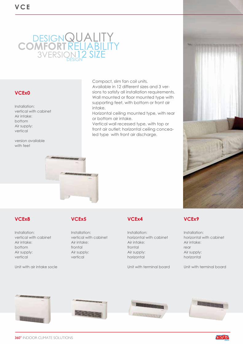
VCEx0
Installation:vertical with cabinetAir intake:bottomAir supply:vertical
version availablewith feet
Compact, slim fan coil units.Available in 12 different sizes and 3 ver-sions to satisfy all installation requirements.Wall mounted or floor mounted type with supporting feet, with bottom or front air intake.Horizontal ceiling mounted type, with rear or bottom air intake.Vertical wall recessed type, with top or front air outlet; horizontal ceiling concea-led type with front air discharge.
VCEx8
Installation:vertical with cabinetAir intake:bottomAir supply:vertical
Unit with air intake socle
VCEx4
Installation:horizontal with cabinetAir intake:frontalAir supply:horizontal
Unit with terminal board
VCEx5
Installation:vertical with cabinetAir intake:frontalAir supply:vertical
VCEx9
Installation:horizontal with cabinetAir intake:rearAir supply:horizontal
Unit with terminal board
www.aliseogroup.com
VCEx1
Installation:horizontal with cabinetAir intake:frontalAir supply:horizontal
Unit with terminal boardUnit with air intake socle
VCEx2
Installation:vertical concealed
Air supply:frontal
Unit with terminal board
VCEx7
Installation:vertical concealed
Air supply:frontal
Unit with terminal board
VCEx3
Installation:horizontal concealed
Air supply:horizontal
Unit with terminal board
V C E
360° INDOOR CLIMATE SOLUTIONS
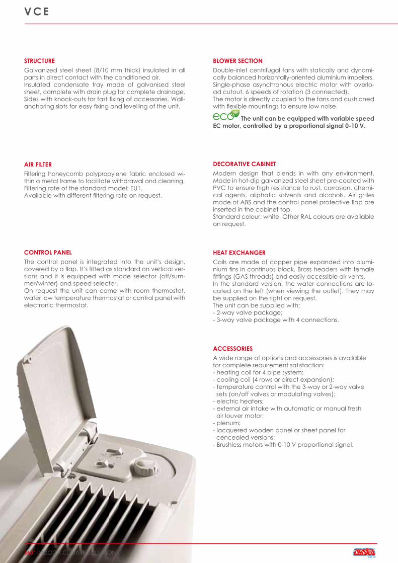
CONTROL PANELThe control panel is integrated into the unit’s design, covered by a flap. It’s fitted as standard on vertical ver-sions and it is equipped with mode selector (off/sum-mer/winter) and speed selector. On request the unit can come with room thermostat, water low temperature thermostat or control panel with electronic thermostat.
ACCESSORIESA wide range of options and accessories is availablefor complete requirement satisfaction:- heating coil for 4 pipe system;- cooling coil (4 rows or direct expansion);- temperature control with the 3-way or 2-way valve sets (on/off valves or modulating valves);- electric heaters;- external air intake with automatic or manual fresh air louver motor;- plenum;- lacquered wooden panel or sheet panel for cencealed versions;- Brushless motors with 0-10 V proportional signal.
STRUCTUREGalvanized steel sheet (8/10 mm thick) insulated in all parts in direct contact with the conditioned air.Insulated condensate tray made of galvanised steel sheet, complete with drain plug for complete drainage.Sides with knock-outs for fast fixing of accessories. Wall-anchoring slots for easy fixing and levelling of the unit.
BLOWER SECTIONDouble-inlet centrifugal fans with statically and dynami-cally balanced horizontally-oriented aluminium impellers.Single-phase asynchronous electric motor with overlo-ad cutout. 6 speeds of rotation (3 connected).The motor is directly coupled to the fans and cushioned with flexible mountings to ensure low noise.
VALVEThe unit can be equipped with variable speed EC motor, controlled by a proportional signal 0-10 V.
HEAT EXCHANGERCoils are made of copper pipe expanded into alumi-nium fins in continuos block. Brass headers with female fittings (GAS threads) and easily accessible air vents.In the standard version, the water connections are lo-cated on the left (when viewing the outlet). They may be supplied on the right on request.The unit can be supplied with:- 2-way valve package;- 3-way valve package with 4 connections.
DECORATIVE CABINETModern design that blends in with any environment. Made in hot-dip galvanized steel sheet pre-coated with PVC to ensure high resistance to rust, corrosion, chemi-cal agents, aliphatic solvents and alcohols. Air grilles made of ABS and the control panel protective flap are inserted in the cabinet top.Standard colour: white. Other RAL colours are available on request.
AIR FILTERFiltering honeycomb polypropylene fabric enclosed wi-thin a metal frame to facilitate withdrawal and cleaning.Filtering rate of the standard model: EU1.Available with different filtering rate on request.
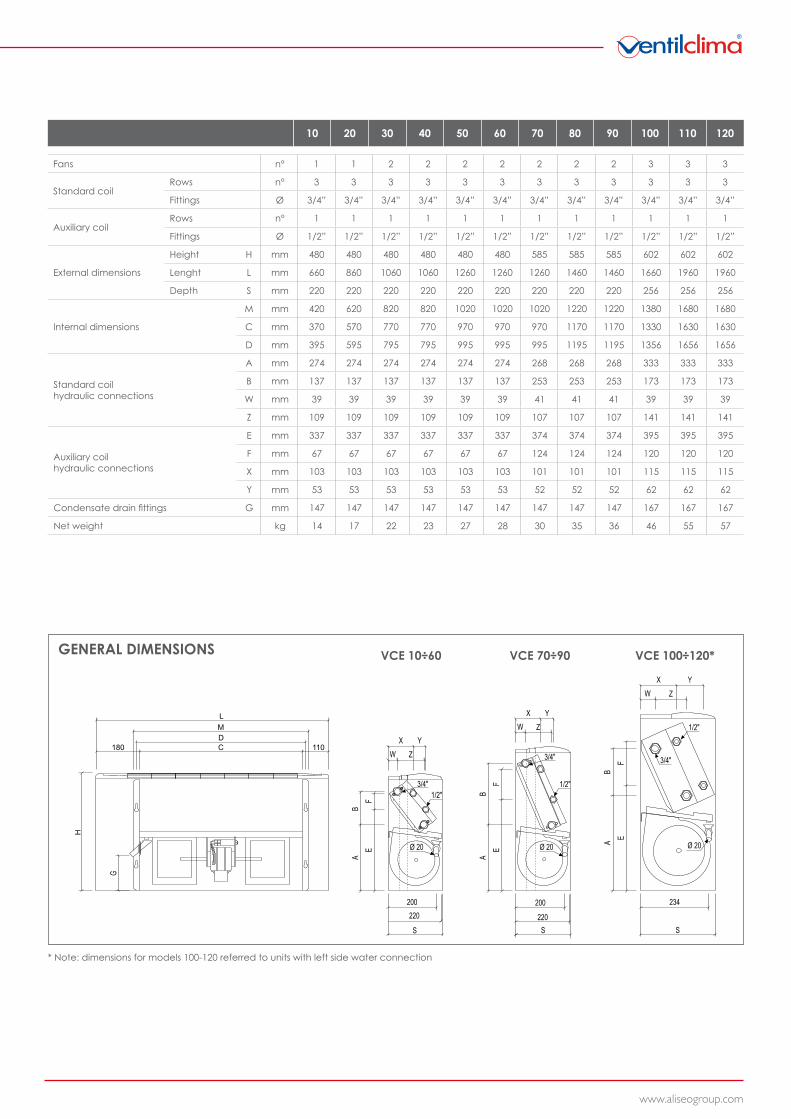
VCE 10÷60 VCE 70÷90 VCE 100÷120*
10 20 30 40 50 60 70 80 90 100 110 120
www.aliseogroup.com
Fans n° 1 1 2 2 2 2 2 2 2 3 3 3
Standard coilRows n° 3 3 3 3 3 3 3 3 3 3 3 3
Fittings Ø 3/4” 3/4” 3/4” 3/4” 3/4” 3/4” 3/4” 3/4” 3/4” 3/4” 3/4” 3/4”
Auxiliary coilRows n° 1 1 1 1 1 1 1 1 1 1 1 1
Fittings Ø 1/2” 1/2” 1/2” 1/2” 1/2” 1/2” 1/2” 1/2” 1/2” 1/2” 1/2” 1/2”
External dimensions
Height H mm 480 480 480 480 480 480 585 585 585 602 602 602
Lenght L mm 660 860 1060 1060 1260 1260 1260 1460 1460 1660 1960 1960
Depth S mm 220 220 220 220 220 220 220 220 220 256 256 256
Internal dimensions
M mm 420 620 820 820 1020 1020 1020 1220 1220 1380 1680 1680
C mm 370 570 770 770 970 970 970 1170 1170 1330 1630 1630
D mm 395 595 795 795 995 995 995 1195 1195 1356 1656 1656
Standard coilhydraulic connections
A mm 274 274 274 274 274 274 268 268 268 333 333 333
B mm 137 137 137 137 137 137 253 253 253 173 173 173
W mm 39 39 39 39 39 39 41 41 41 39 39 39
Z mm 109 109 109 109 109 109 107 107 107 141 141 141
Auxiliary coilhydraulic connections
E mm 337 337 337 337 337 337 374 374 374 395 395 395
F mm 67 67 67 67 67 67 124 124 124 120 120 120
X mm 103 103 103 103 103 103 101 101 101 115 115 115
Y mm 53 53 53 53 53 53 52 52 52 62 62 62
Condensate drain fittings G mm 147 147 147 147 147 147 147 147 147 167 167 167
Net weight kg 14 17 22 23 27 28 30 35 36 46 55 57
GENERAL DIMENSIONS
* Note: dimensions for models 100-120 referred to units with left side water connection
200
S
200
S S
Ø 20
234
1/2"
3/4"
1/2"
3/4"
1/2"3/4"
Ø 20Ø 20
G
AE
FB
W Z
X Y
AE
FB
W Z
X Y
A EF
B
W Z
X Y
220 220
L
H
MDC180 110
10 20 30 40 50 60 70 80 90 100 110 120
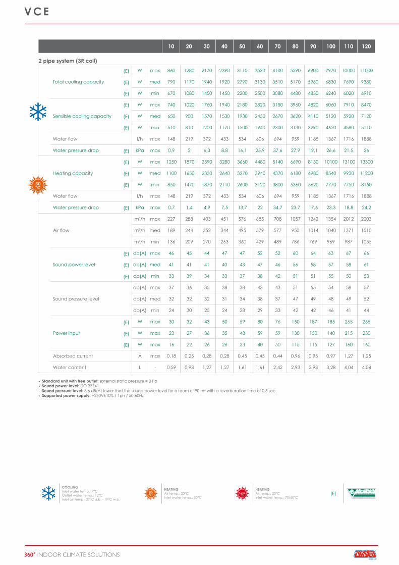
COOLINGInlet water temp.: 7°COutlet water temp.: 12°CInlet air temp.: 27°C d.b. - 19°C w.b.
HEATINGAir temp.: 20°CInlet water temp.: 50°C
HEATINGAir temp.: 20°CInlet water temp.: 70/60°C
(E)
(E)
(E)
(E)
(E)
(E)
(E)
(E)
(E)
(E)
(E)
(E)
(E)
(E)
(E)
(E)
(E)
(E)
V C E
360° INDOOR CLIMATE SOLUTIONS
----
Standard unit with free outlet: external static pressure = 0 PaSound power level: ISO 23741Sound pressure level: 8,6 dB(A) lower that the sound power level for a room of 90 m3 with a reverberation time of 0,5 sec.Supported power supply: ~230V±10% / 1ph / 50-60Hz
2 pipe system (3R coil)
Total cooling capacity
W max 860 1280 2170 2390 3110 3530 4100 5590 6900 7970 10000 11000
W med 790 1170 1940 1920 2790 3130 3510 5170 5960 6830 7690 9380
W min 670 1080 1450 1450 2200 2500 3080 4480 4830 6240 6020 6910
Sensible cooling capacity
W max 740 1020 1760 1940 2180 2820 3150 3960 4820 6060 7910 8470
W med 650 900 1570 1530 1930 2450 2670 3620 4110 5120 5920 7120
W min 510 810 1200 1170 1500 1940 2300 3130 3290 4620 4580 5110
Water flow l/h max 148 219 372 433 534 606 694 959 1185 1367 1716 1888
Water pressure drop kPa max 0,9 2 6,3 8,8 16,1 25,9 37,6 27,9 19,1 26,6 21,5 26
Heating capacity
W max 1250 1870 2590 3280 3660 4480 5140 6690 8130 10100 13100 13300
W med 1100 1650 2330 2640 3270 3940 4370 6180 6980 8540 9930 11200
W min 850 1470 1870 2110 2600 3120 3800 5360 5620 7770 7750 8150
Water flow l/h max 148 219 372 433 534 606 694 959 1185 1367 1716 1888
Water pressure drop kPa max 0,7 1,4 4,9 7,5 13,7 22 34,7 23,7 17,6 23,3 18,8 24,2
Air flow
m3/h max 227 288 403 451 576 685 708 1057 1242 1354 2012 2003
m3/h med 189 244 352 344 495 579 577 950 1014 1040 1371 1510
m3/h min 136 209 270 263 360 429 489 786 769 969 987 1055
Sound power level
db(A) max 46 45 44 47 47 52 52 60 64 63 67 66
db(A) med 41 41 41 40 43 47 46 56 58 57 58 61
db(A) min 33 39 34 33 37 38 42 51 51 55 50 53
Sound pressure level
db(A) max 37 36 35 38 38 43 43 51 55 54 58 57
db(A) med 32 32 32 31 34 38 37 47 49 48 49 52
db(A) min 24 30 25 24 28 29 33 42 42 46 41 44
Power input
W max 30 32 43 50 59 80 76 150 187 185 265 265
W max 23 27 36 35 48 59 59 130 150 140 215 230
W max 16 22 26 26 33 40 50 115 115 127 160 160
Absorbed current A max 0,18 0,25 0,28 0,28 0,45 0,45 0,44 0,96 0,95 0,97 1,27 1,25
Water content L - 0,59 0,93 1,27 1,27 1,61 1,61 2,42 2,93 2,93 3,28 4,04 4,04
10 20 30 40 50 60 70 80 90 100 110 120
COOLINGInlet water temp.: 7°COutlet water temp.: 12°CInlet air temp.: 27°C d.b. - 19°C w.b.
HEATINGAir temp.: 20°CInlet water temp.: 50°C
HEATINGAir temp.: 20°CInlet water temp.: 70/60°C
(E)
(E)
(E)
(E)
(E)
(E)
(E)
(E)
(E)
(E)
(E)
(E)
(E)
(E)
(E)
(E)
www.aliseogroup.com
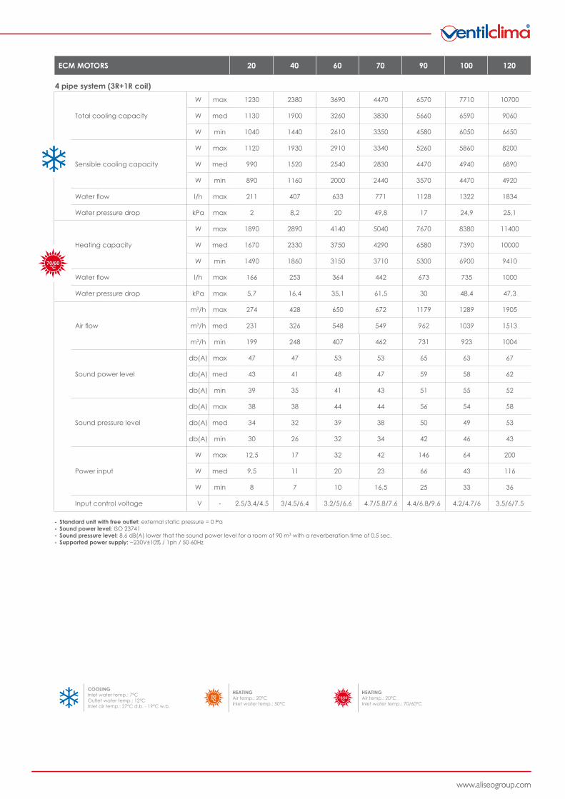
4 pipe system (3R+1R coil)
Total cooling capacity
W max 840 1230 2080 2380 2760 3690 4470 5350 6570 7710 9700 10700
W med 770 1130 1850 1900 2480 3260 3830 4950 5660 6590 7430 9060
W min 650 1040 1380 1440 1960 2610 3350 4280 4580 6050 5790 6650
Sensible cooling capacity
W max 710 1120 1600 1930 2220 2910 3340 4110 5260 5860 7660 8200
W med 630 990 1430 1520 1960 2540 2830 3760 4470 4940 5720 6890
W min 500 890 1090 1160 1530 2000 2440 3260 3570 4470 4400 4920
Water flow l/h max 144 211 357 407 473 633 771 917 1128 1322 1663 1834
Water pressure drop kPa max 0,61 2 5,7 8,2 10,7 20 49,8 11,6 17 24,9 21,7 25,1
Heating capacity
W max 1260 1890 2730 2890 3490 4140 5040 6210 7670 8380 10100 11400
W med 1110 1670 2450 2330 3120 3750 4290 5840 6580 7390 8160 10000
W min 860 1490 1970 1860 2450 3150 3710 5240 5300 6900 6750 9410
Water flow l/h max 111 166 239 253 306 363 442 545 673 735 886 1000
Water pressure drop kPa max 2,1 5,7 13,9 16,4 27,9 35,1 61,5 22 30 48,4 41,3 58,5
Air flow
m3/h max 216 274 383 428 545 650 672 1003 1179 1289 1913 1905
m3/h med 180 231 333 326 469 548 549 901 962 1039 1304 1513
m3/h min 128 200 256 249 343 407 463 749 731 923 941 1004
Sound power level
db(A) max 45 47 44 47 46 53 53 59 65 63 67 67
db(A) med 40 43 40 41 42 48 47 57 59 58 58 62
db(A) min 34 39 34 35 35 41 43 51 51 55 51 52
Sound pressure level
db(A) max 36 38 35 38 37 44 44 50 56 54 58 58
db(A) med 31 34 31 32 33 39 38 48 50 49 49 53
db(A) min 25 30 25 26 26 32 34 42 42 46 42 43
Power input
W max 30 32 43 50 59 80 76 150 187 185 265 265
W med 23 27 36 35 48 59 59 130 150 140 215 230
W min 16 22 26 26 33 40 50 115 115 127 160 160
Absorbed current A max 0,18 0,25 0,28 0,28 0,45 0,45 0,44 0,96 0,95 0,97 1,27 1,25
Water content (3R coil) L - 0,59 0,93 1,27 1,27 1,61 1,61 2,42 2,93 2,93 3,28 4,04 4,04
Water content (1R coil) L - 0,19 0,31 0,42 0,42 0,53 0,53 0,53 1,29 1,29 1,09 1,35 1,35
----
Standard unit with free outlet: external static pressure = 0 PaSound power level: ISO 23741Sound pressure level: 8,6 dB(A) lower that the sound power level for a room of 90 m3 with a reverberation time of 0,5 sec.Supported power supply: ~230V±10% / 1ph / 50-60Hz
(E)
(E)
(E)
(E)
(E)
(E)
(E)
(E)
(E)
(E)
(E)
(E)
(E)
(E)
(E)
(E)
(E)
V C E
360° INDOOR CLIMATE SOLUTIONS
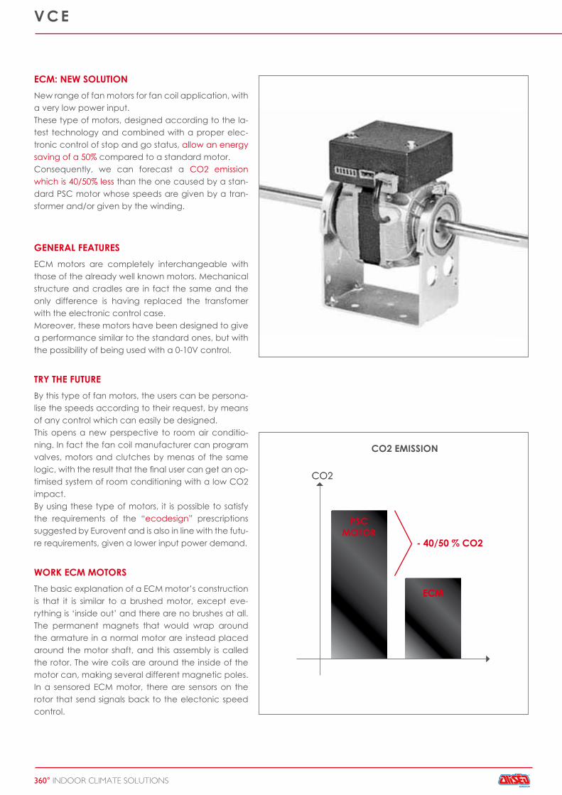
CO2CO2
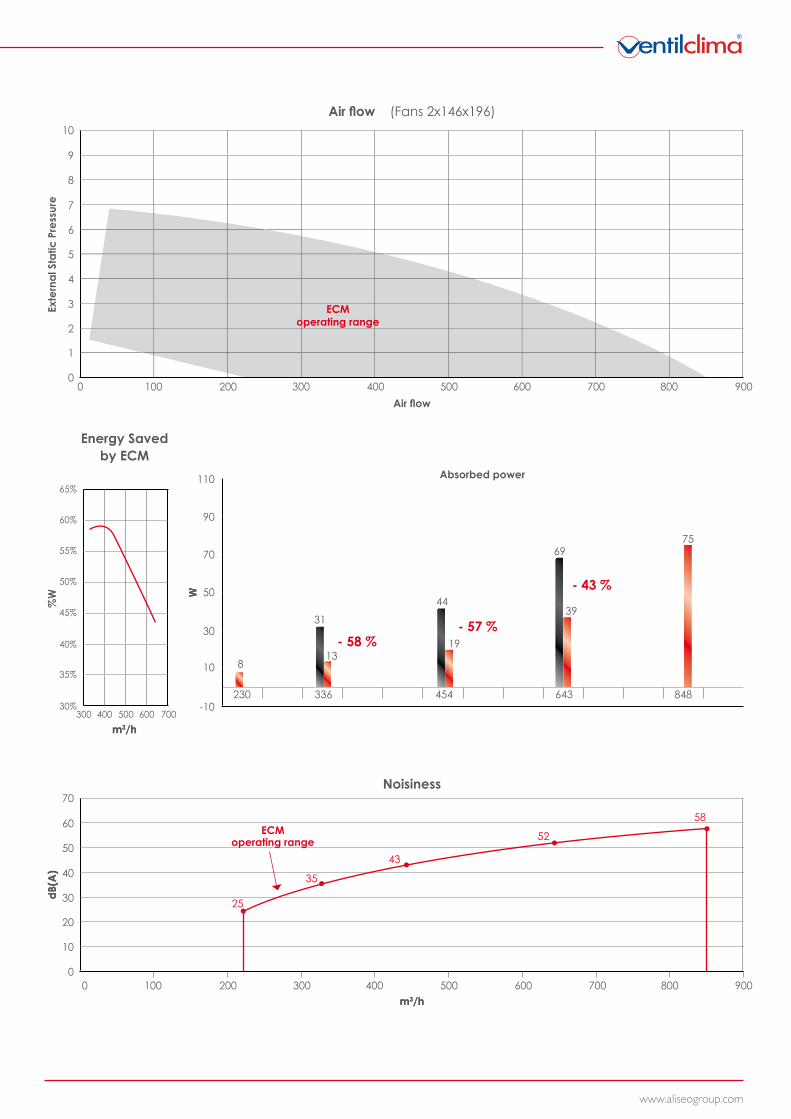
ECM
- 40/50 % CO2
ECM
ECM: NEW SOLUTIONNew range of fan motors for fan coil application, with a very low power input.These type of motors, designed according to the la-test technology and combined with a proper elec-tronic control of stop and go status, allow an energy saving of a 50% compared to a standard motor.Consequently, we can forecast a CO2 emission which is 40/50% less than the one caused by a stan-dard PSC motor whose speeds are given by a tran-sformer and/or given by the winding.
GENERAL FEATURESECM motors are completely interchangeable with those of the already well known motors. Mechanical structure and cradles are in fact the same and the only difference is having replaced the transfomer with the electronic control case.Moreover, these motors have been designed to give a performance similar to the standard ones, but with the possibility of being used with a 0-10V control.
TRY THE FUTUREBy this type of fan motors, the users can be persona-lise the speeds according to their request, by means of any control which can easily be designed.This opens a new perspective to room air conditio-ning. In fact the fan coil manufacturer can program valves, motors and clutches by menas of the same logic, with the result that the final user can get an op-timised system of room conditioning with a low CO2 impact.By using these type of motors, it is possible to satisfy the requirements of the “ecodesign” prescriptions suggested by Eurovent and is also in line with the futu-re requirements, given a lower input power demand.
WORK ECM MOTORSThe basic explanation of a ECM motor’s construction is that it is similar to a brushed motor, except eve-rything is ‘inside out’ and there are no brushes at all. The permanent magnets that would wrap around the armature in a normal motor are instead placed around the motor shaft, and this assembly is called the rotor. The wire coils are around the inside of the motor can, making several different magnetic poles. In a sensored ECM motor, there are sensors on the rotor that send signals back to the electonic speed control.
CO2 EMISSION
PSCMOTOR
www.aliseogroup.com
10000
4
2
6
8
1
5
3
7
9
10
300 500 700200 400 600 800 900
30%300 400 500 600 700
40%
50%
60%
35%
45%
55%
65%
230 336 454 643 848-10
10
30
50
70
90
110
8
31
13
44
19
69
39
75
- 58 %- 57 %
- 43 %
W
0
10
30
50
20
0
40
60
70
25
35
43
52
58
100 200 300 400 500 600 700 800 900
Air flow
m3/h
W
m3/h
dB(A
)
m3/h
m3/h
dB(A
)%
W
Air flow (Fans 2x146x196)
Exte
rnal
Sta
tic P
ress
ure
ECMoperating range
Energy Savedby ECM
Absorbed power
Noisiness
ECMoperating range
V C E
360° INDOOR CLIMATE SOLUTIONS
V C E
360° INDOOR CLIMATE SOLUTIONS
ECM MOTORS 20 40 60 70 90 100 120
2 pipe system (3R coil)
Total cooling capacity
W max 1280 2390 3530 4100 6900 7970 11000
W med 1170 1920 3130 3510 5960 6830 9380
W min 1080 1450 2500 3080 4830 6240 6910
Sensible cooling capacity
W max 1020 1940 2820 3150 4820 6060 8470
W med 900 1530 2450 2670 4110 5120 7120
W min 810 1170 1940 2300 3290 4620 5110
Water flow l/h max 220 433 606 693 1184 1366 1888
Water pressure drop kPa max 2 8,8 25,9 37,6 19,1 26,6 26
Heating capacity
W max 1870 3280 4480 5140 8130 10100 13300
W med 1650 2640 3940 4370 6980 8540 11200
W min 1470 2110 3120 3800 5620 7770 8150
Water flow l/h max 220 433 606 693 1184 1366 1888
Water pressure drop kPa max 1,4 7,5 22 34,7 17,6 23,3 24,2
Air flow
m3/h max 288 450 685 708 1242 1354 2003
m3/h med 243 344 578 578 1014 1040 1510
m3/h min 210 263 429 489 769 969 1055
Sound power level
db(A) max 45 47 52 52 64 63 66
db(A) med 41 40 47 46 58 57 61
db(A) min 37 33 38 42 51 55 53
Sound pressure level
db(A) max 36 38 43 43 55 54 57
db(A) med 32 31 38 37 49 48 52
db(A) min 28 24 29 33 42 46 44
Power input
W max 12,5 17 32 42 146 64 200
W med 9,5 11 20 23 66 43 116
W min 8 7 10 16,5 25 33 36
Input control voltage V - 2.5/3.4/4.5 3/4.5/6.4 3.2/5/6.6 4.7/5.8/7.6 4.4/6.8/9.6 4.2/4.7/6 3.5/6/7.5
----
Standard unit with free outlet: external static pressure = 0 PaSound power level: ISO 23741Sound pressure level: 8,6 dB(A) lower that the sound power level for a room of 90 m3 with a reverberation time of 0,5 sec.Supported power supply: ~230V±10% / 1ph / 50-60Hz
COOLINGInlet water temp.: 7°COutlet water temp.: 12°CInlet air temp.: 27°C d.b. - 19°C w.b.
HEATINGAir temp.: 20°CInlet water temp.: 50°C
HEATINGAir temp.: 20°CInlet water temp.: 70/60°C
www.aliseogroup.comwww.aliseogroup.com
ECM MOTORS 20 40 60 70 90 100 120
4 pipe system (3R+1R coil)
Total cooling capacity
W max 1230 2380 3690 4470 6570 7710 10700
W med 1130 1900 3260 3830 5660 6590 9060
W min 1040 1440 2610 3350 4580 6050 6650
Sensible cooling capacity
W max 1120 1930 2910 3340 5260 5860 8200
W med 990 1520 2540 2830 4470 4940 6890
W min 890 1160 2000 2440 3570 4470 4920
Water flow l/h max 211 407 633 771 1128 1322 1834
Water pressure drop kPa max 2 8,2 20 49,8 17 24,9 25,1
Heating capacity
W max 1890 2890 4140 5040 7670 8380 11400
W med 1670 2330 3750 4290 6580 7390 10000
W min 1490 1860 3150 3710 5300 6900 9410
Water flow l/h max 166 253 364 442 673 735 1000
Water pressure drop kPa max 5,7 16,4 35,1 61,5 30 48,4 47,3
Air flow
m3/h max 274 428 650 672 1179 1289 1905
m3/h med 231 326 548 549 962 1039 1513
m3/h min 199 248 407 462 731 923 1004
Sound power level
db(A) max 47 47 53 53 65 63 67
db(A) med 43 41 48 47 59 58 62
db(A) min 39 35 41 43 51 55 52
Sound pressure level
db(A) max 38 38 44 44 56 54 58
db(A) med 34 32 39 38 50 49 53
db(A) min 30 26 32 34 42 46 43
Power input
W max 12,5 17 32 42 146 64 200
W med 9,5 11 20 23 66 43 116
W min 8 7 10 16,5 25 33 36
Input control voltage V - 2.5/3.4/4.5 3/4.5/6.4 3.2/5/6.6 4.7/5.8/7.6 4.4/6.8/9.6 4.2/4.7/6 3.5/6/7.5
----
Standard unit with free outlet: external static pressure = 0 PaSound power level: ISO 23741Sound pressure level: 8,6 dB(A) lower that the sound power level for a room of 90 m3 with a reverberation time of 0,5 sec.Supported power supply: ~230V±10% / 1ph / 50-60Hz
COOLINGInlet water temp.: 7°COutlet water temp.: 12°CInlet air temp.: 27°C d.b. - 19°C w.b.
HEATINGAir temp.: 20°CInlet water temp.: 50°C
HEATINGAir temp.: 20°CInlet water temp.: 70/60°C
A GROUP S.p.A. - Via Montegrappa, 67 - 31020 San Zenone degli Ezzelini (Treviso) - ItalyTel. +39 0423 567774 - Fax +39 0423 567985 - www.aliseogroup.com - [email protected]
DP V
CE 2
014-
0 GB
A GROUP TAKES PART TO THE EUROVENT PROGRAMOF FAN COIL PERFORMANCE CERTIFICATIONIN ORDER TO PROVIDE ITS CUSTOMERS THE RELIABILITYAND ACCURACY OF PERFORMANCES.