central extract system - johnson & starley · 2.1 ce300 central extract system provides ......
TRANSCRIPT

R E L I A B I L I T Y Y O U C A N T R U S T
Johnson & Starley
Publication No. ZZ 1290 July 2007
CE300CENTRAL EXTRACT SYSTEM
www.johnsonandstarley.co.uk
Installation, Commissioning& Servicing Instructions
�
CONTENTS
1 Features 3
2 GeneralDescription 3
3 BuildingStandards&Regulations 4
4 TechnicalData 4
5 Preparation&SafetyNotes 4
6 InstallationInstructions 7
7 Electrical 7
8 Commissioning 9
9 Servicing&Maintenance 10
10 InstructionforUser 11
11 Dimensions 12
12 Notes 13
13 SparesList 14
14 ExplodedDiagram 15
�
�
1. FEATURES
2. GENERAL DESCRIPTION
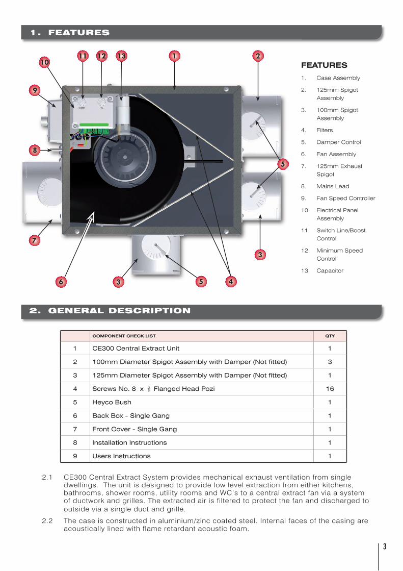
2.1 CE300CentralExtractSystemprovidesmechanicalexhaustventilationfromsingledwellings.Theunitisdesignedtoprovidelowlevelextractionfromeitherkitchens,bathrooms,showerrooms,utilityroomsandWC’stoacentralextractfanviaasystemofductworkandgrilles.Theextractedairisfilteredtoprotectthefananddischargedtooutsideviaasingleductandgrille.
2.2 Thecaseisconstructedinaluminium/zinccoatedsteel.Internalfacesofthecasingareacousticallylinedwithflameretardantacousticfoam.
FEATURES
1. Case Assembly
2. 125mm Spigot
Assembly
3. 100mm Spigot
Assembly
4. Filters
5. Damper Control
6. Fan Assembly
7. 125mm Exhaust
Spigot
8. Mains Lead
9. Fan Speed Controller
10. Electrical Panel
Assembly
11. Switch Line/Boost
Control
12. Minimum Speed
Control
13. Capacitor
COMPONENT CHECK LIST QTY
1 CE300CentralExtractUnit 1
2 100mmDiameterSpigotAssemblywithDamper(Notfitted) 3
3 125mmDiameterSpigotAssemblywithDamper(Notfitted) 1
4 ScrewsNo.8x*FlangedHeadPozi 16
5 HeycoBush 1
6 BackBox-SingleGang 1
7 FrontCover-SingleGang 1
8 InstallationInstructions 1
9 UsersInstructions 1
1
3
436
21211
9
10
8
13
5
7
5

�
3. BUILDING STANDARDS & REGULATIONS
Installationshallbeinaccordancewiththefollowing:-
Building Standards(ScotlandConsolidation)Regulations
Part F of the Building Regulations
British Standard BS7671
Institute of Electrical Engineers (I.E.E.)Regulations
Good Practice Guide 268
4. TECHNICAL DATA
Volts:- 230V~ 50Hz
Input:- 17WMin-83WMax
Fuserating:- 3A
5. PREPARATION AND SAFETY NOTES
5.1 SAFETY INFORMATION
5.1.1 Ensurethemainssupplyvoltage,frequency,numberofphasesandpower ratingcomplywithdetailsontheratinglabelontheunit.
5.1.2 Allwiringmustbeinaccordancewiththeappropriatestandards.Theequipment mustbeprovidedwithalocaldoublepoleisolatorswitch.
5.1.3 Ensuresafetyregulationsandpracticesareadheredtowheninstallingandusing thisequipment.
5.1.4 Whenafanisusedinorextractingfromaroomwithafuelburningappliance, theinstallermustensurethereplacementairisadequateforboththefanandthe fuelburningappliance.
5.1.5 Donotinstallthisappliancewhereitisliabletobesubjecttowatersprayor whereductedairambienttemperaturemayexceed40˚C.
GROUND FLOOR FIRST FLOOR
TYPICAL HOUSE LAYOUT

�
�
5.1.6 Whenthefanisusedtohandlemoistair,asuitablecondensatetrapanddrainage systemshouldbeincorporatedintheexhaustducttoensuresafeandhealthy operatingconditions.
5.1.7 DONOTusethisappliancewhereexcessivemoisture,excessivedustorfibres, greaseoroilladenair,corrosiveorflammableatmospheresarepresent.
5.1.8 Wheninstallingtheunit,takecarenottodamageelectricalorotherhidden utilities.
5.1.9 Exhaustairmustbeventedtotheoutside.
5.1.10Thefanmotorisfittedwithsealedforlifebearingsandthereforedoesnotrequire lubrication.
5.2 DUCTING INFORMATION
5.2.1 Itisanadvantagetohaveallthecompatibleductworkalreadyinstalledandready toconnecttotheinletspigots.
5.2.2 Anyoralloftheseconnectionspigotscanbeused,eachwithindividualvolume controlbeingavailableviathedampers.
5.2.3 Ductingpassingthroughunheatedroofvoidsshouldbeinsulated.Ductingruns shouldbeasstraightaspossibleandthehorizontalexhaustductingshould alwaysslopedownwardsfromtheCE300unit.
5.2.4 Therecommendedtypesofductingare:-flexibleduct,ridgedplasticductand spiralwoundduct.ThesecanallbeusedwiththeCE300unit.
5.2.5 ForanyexhaustductpassingthrougharoofuseasuitableVerticalTerminalor RidgeTerminal.Fordetailsonthesecontactoursalesdepartmentforfurther information.
5.2.6 PLEASENOTE-donotallowtheductingtooverlapthedampercontrol.
TYPICAL FLAT LAYOUT
�
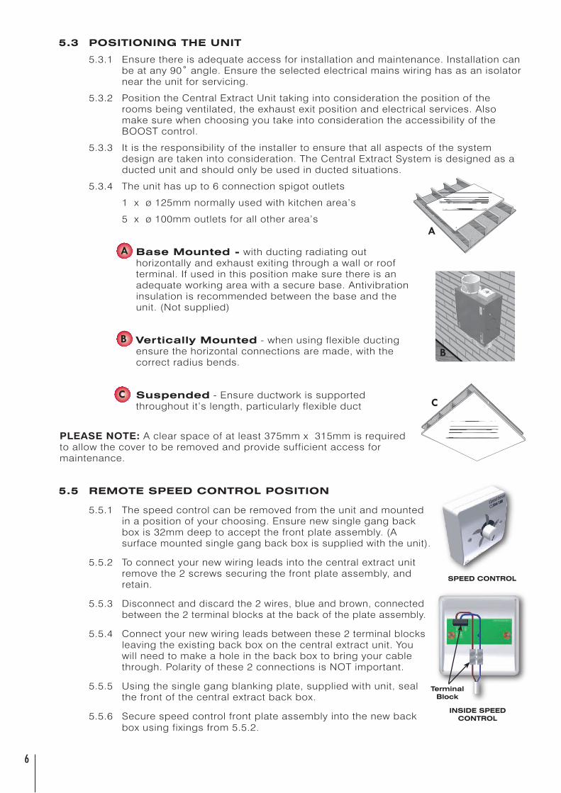
5.3 POSITIONING THE UNIT
5.3.1 Ensurethereisadequateaccessforinstallationandmaintenance.Installationcan beatany90˚angle.Ensuretheselectedelectricalmainswiringhasasanisolator neartheunitforservicing.
5.3.2 PositiontheCentralExtractUnittakingintoconsiderationthepositionofthe roomsbeingventilated,theexhaustexitpositionandelectricalservices.Also makesurewhenchoosingyoutakeintoconsiderationtheaccessibilityofthe BOOSTcontrol.
5.3.3 Itistheresponsibilityoftheinstallertoensurethatallaspectsofthesystem designaretakenintoconsideration.TheCentralExtractSystemisdesignedasa ductedunitandshouldonlybeusedinductedsituations.
5.3.4 Theunithasupto6connectionspigotoutlets
1xø125mmnormallyusedwithkitchenarea’s
5xø100mmoutletsforallotherarea’s
a. Base Mounted -withductingradiatingout horizontallyandexhaustexitingthroughawallorroof terminal.Ifusedinthispositionmakesurethereisan adequateworkingareawithasecurebase.Antivibration insulationisrecommendedbetweenthebaseandthe unit.(Notsupplied)
b. Vertically Mounted-whenusingflexibleducting ensurethehorizontalconnectionsaremade,withthe correctradiusbends.
c. Suspended-Ensureductworkissupported throughoutit’slength,particularlyflexibleduct
PLEASENOTE:Aclearspaceofatleast375mmx315mmisrequiredtoallowthecovertoberemovedandprovidesufficientaccessformaintenance.
5.5 REMOTE SPEED CONTROL POSITION
5.5.1 Thespeedcontrolcanberemovedfromtheunitandmounted inapositionofyourchoosing.Ensurenewsinglegangback boxis32mmdeeptoacceptthefrontplateassembly.(A surfacemountedsinglegangbackboxissuppliedwiththeunit).
5.5.2 Toconnectyournewwiringleadsintothecentralextractunit removethe2screwssecuringthefrontplateassembly,and retain.
5.5.3 Disconnectanddiscardthe2wires,blueandbrown,connected betweenthe2terminalblocksatthebackoftheplateassembly.
5.5.4 Connectyournewwiringleadsbetweenthese2terminalblocks leavingtheexistingbackboxonthecentralextractunit.You willneedtomakeaholeinthebackboxtobringyourcable through.Polarityofthese2connectionsisNOTimportant.
5.5.5 Usingthesinglegangblankingplate,suppliedwithunit,seal thefrontofthecentralextractbackbox.
5.5.6 Securespeedcontrolfrontplateassemblyintothenewback boxusingfixingsfrom5.5.2.
A
INSIDE SPEED CONTROL
SPEED CONTROL
TerminalBlock
B
C
A
B
C
�
�
6. INSTALLATION INSTRUCTIONS
NOTE:Theinstallationshouldbecarriedoutbyacompetentpersoninaccordancewiththeappropriateauthorityandconformingtoallthestatutoryandgoverningregulations.
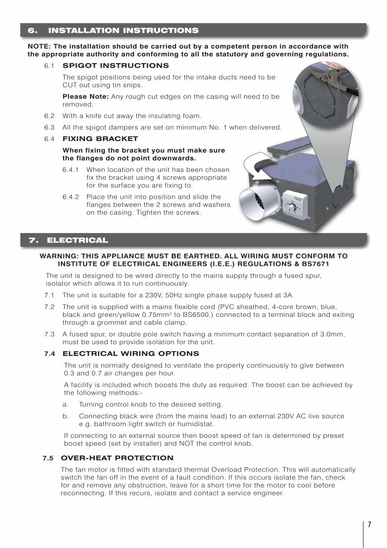
6.1 SPIGOT INSTRUCTIONS
ThespigotpositionsbeingusedfortheintakeductsneedtobeCUToutusingtinsnips.
PleaseNote:Anyroughcutedgesonthecasingwillneedtoberemoved.
6.2 Withaknifecutawaytheinsulatingfoam.
6.3 AllthespigotdampersaresetonminimumNo.1whendelivered.
6.4 FIXING BRACKET
Whenfixingthebracketyoumustmakesuretheflangesdonotpointdownwards.
6.4.1 Whenlocationoftheunithasbeenchosen fixthebracketusing4screwsappropriate forthesurfaceyouarefixingto.
6.4.2 Placetheunitintopositionandslidethe flangesbetweenthe2screwsandwashers onthecasing.Tightenthescrews.
7. ELECTRICAL
WARNING:THISAPPLIANCEMUSTBEEARTHED.ALLWIRINGMUSTCONFORMTOINSTITUTEOFELECTRICALENGINEERS(I.E.E.)REGULATIONS& BS7671
Theunitisdesignedtobewireddirectlytothemainssupplythroughafusedspur, isolatorwhichallowsittoruncontinuously.
7.1 Theunitissuitablefora230V,50Hzsinglephasesupplyfusedat3A.
7.2 Theunitissuppliedwithamainsflexiblecord(PVCsheathed,4-corebrown,blue,blackandgreen/yellow0.75mm²toBS6500,)connectedtoaterminalblockandexitingthroughagrommetandcableclamp.
7.3 Afusedspur,ordoublepoleswitchhavingaminimumcontactseparationof3.0mm,mustbeusedtoprovideisolationfortheunit.
7.4 ELECTRICAL WIRING OPTIONS
Theunitisnormallydesignedtoventilatethepropertycontinuouslytogivebetween 0.3and0.7airchangesperhour.
Afacilityisincludedwhichbooststhedutyasrequired.Theboostcanbeachievedby thefollowingmethods:-
a. Turningcontrolknobtothedesiredsetting.
b. Connectingblackwire(fromthemainslead)toanexternal230VAClivesource e.g.bathroomlightswitchorhumidistat.
Ifconnectingtoanexternalsourcethenboostspeedoffanisdeterminedbypreset boostspeed(setbyinstaller)andNOTthecontrolknob.
7.5 OVER-HEAT PROTECTION
ThefanmotorisfittedwithstandardthermalOverloadProtection.Thiswillautomaticallyswitchthefanoffintheeventofafaultcondition.Ifthisoccursisolatethefan,checkforandremoveanyobstruction,leaveforashorttimeforthemotortocoolbeforereconnecting.Ifthisrecurs,isolateandcontactaserviceengineer.
�
MIN SPEED 0 1 2 3 4 5 MAX SPEED
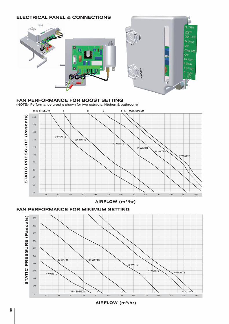
FAN PERFORMANCE FOR BOOST SETTING(NOTE:-Performancegraphsshownfortwoextracts,kitchen&bathroom)
ELECTRICAL PANEL & CONNECTIONS
FAN PERFORMANCE FOR MINIMUM SETTING
S
TA
TIC
PR
ES
SU
RE
(P
as
ca
ls)
200
180
160
140
120
100
80
60
40
20
010 30 50 70 90 110 130 150 170 190 210 230 250
AIRFLOW (m³/hr)
33 WATTS37 WATTS
47 WATTS
51 WATTS
55 WATTS
57 WATTS
S
TA
TIC
PR
ES
SU
RE
(P
as
ca
ls)
200
180
160
140
120
100
80
60
40
20
010 30 50 70 90 110 130 150 170 190 210 230 250
AIRFLOW (m³/hr)
17 WATTS
22 WATTS 30 WATTS
40 WATTS
47 WATTS48 WATTS
MIN SPEED 0 1 2 3 4 5
�
�
8. COMMISSIONING
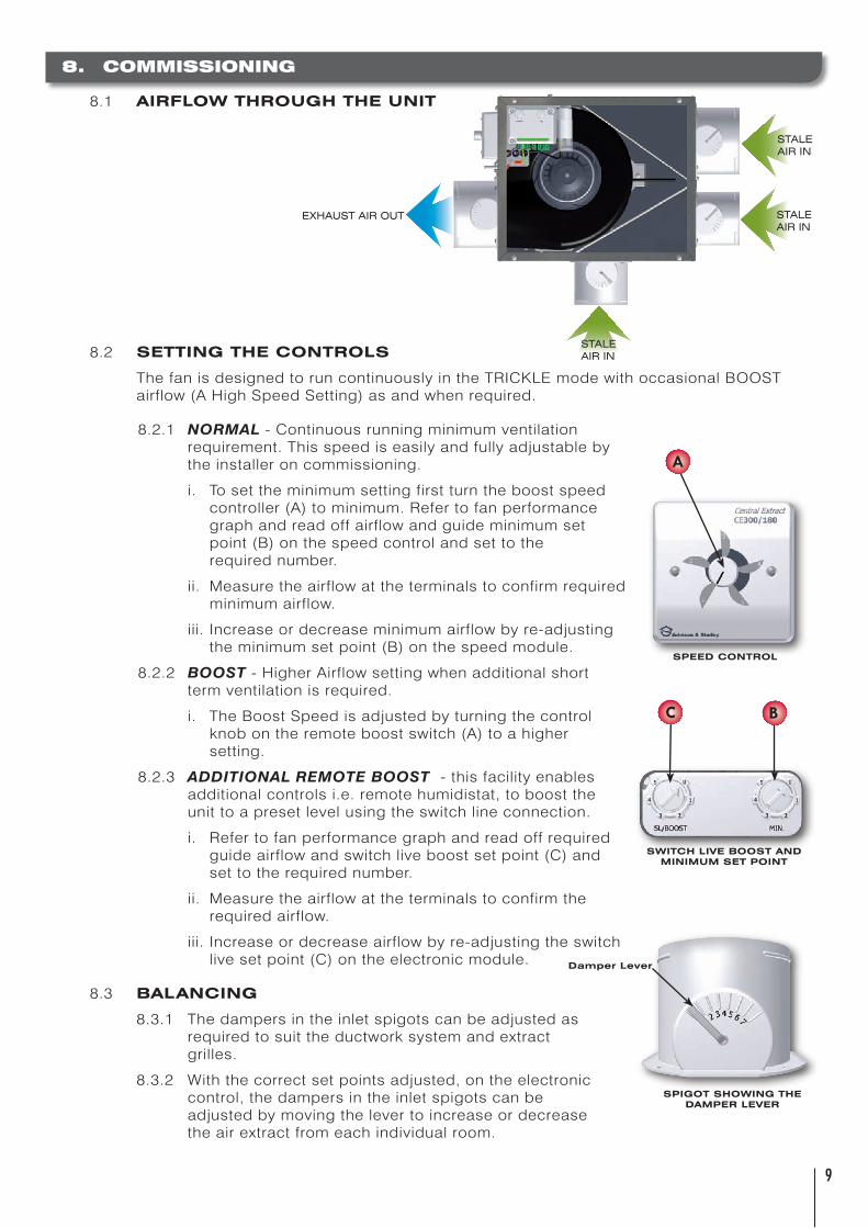
8.1 AIRFLOW THROUGH THE UNIT
8.2 SETTING THE CONTROLS
ThefanisdesignedtoruncontinuouslyintheTRICKLEmodewithoccasionalBOOSTairflow(AHighSpeedSetting)asandwhenrequired.
8.2.1 NORMAL-Continuousrunningminimumventilation requirement.Thisspeediseasilyandfullyadjustableby theinstalleroncommissioning.
i. Tosettheminimumsettingfirstturntheboostspeed controller(A)tominimum.Refertofanperformance graphandreadoffairflowandguideminimumset point(B)onthespeedcontrolandsettothe requirednumber.
ii. Measuretheairflowattheterminalstoconfirmrequired minimumairflow.
iii.Increaseordecreaseminimumairflowbyre-adjusting theminimumsetpoint(B)onthespeedmodule.
8.2.2 BOOST-HigherAirflowsettingwhenadditionalshort termventilationisrequired.
i. TheBoostSpeedisadjustedbyturningthecontrol knobontheremoteboostswitch(A)toahigher setting.
8.2.3 ADDITIONALREMOTEBOOST-thisfacilityenables additionalcontrolsi.e.remotehumidistat,toboostthe unittoapresetlevelusingtheswitchlineconnection.
i. Refertofanperformancegraphandreadoffrequired guideairflowandswitchliveboostsetpoint(C)and settotherequirednumber.
ii. Measuretheairflowattheterminalstoconfirmthe requiredairflow.
iii.Increaseordecreaseairflowbyre-adjustingtheswitch livesetpoint(C)ontheelectronicmodule.
8.3 BALANCING
8.3.1 Thedampersintheinletspigotscanbeadjustedas requiredtosuittheductworksystemandextract grilles.
8.3.2 Withthecorrectsetpointsadjusted,ontheelectronic control,thedampersintheinletspigotscanbe adjustedbymovingthelevertoincreaseordecrease theairextractfromeachindividualroom.
EXHAUSTAIROUT
STALEAIRIN
STALEAIRIN
STALEAIRIN
A
C B
SPEED CONTROL
SWITCH LIVE BOOST AND MINIMUM SET POINT
SPIGOT SHOWING THE DAMPER LEVER
Damper Lever
10
8.3.3 Refertothedesigndrawingorspecificationsheetandmeasuretheairflowatthe terminalsandre-adjustthedamperswhererequired.
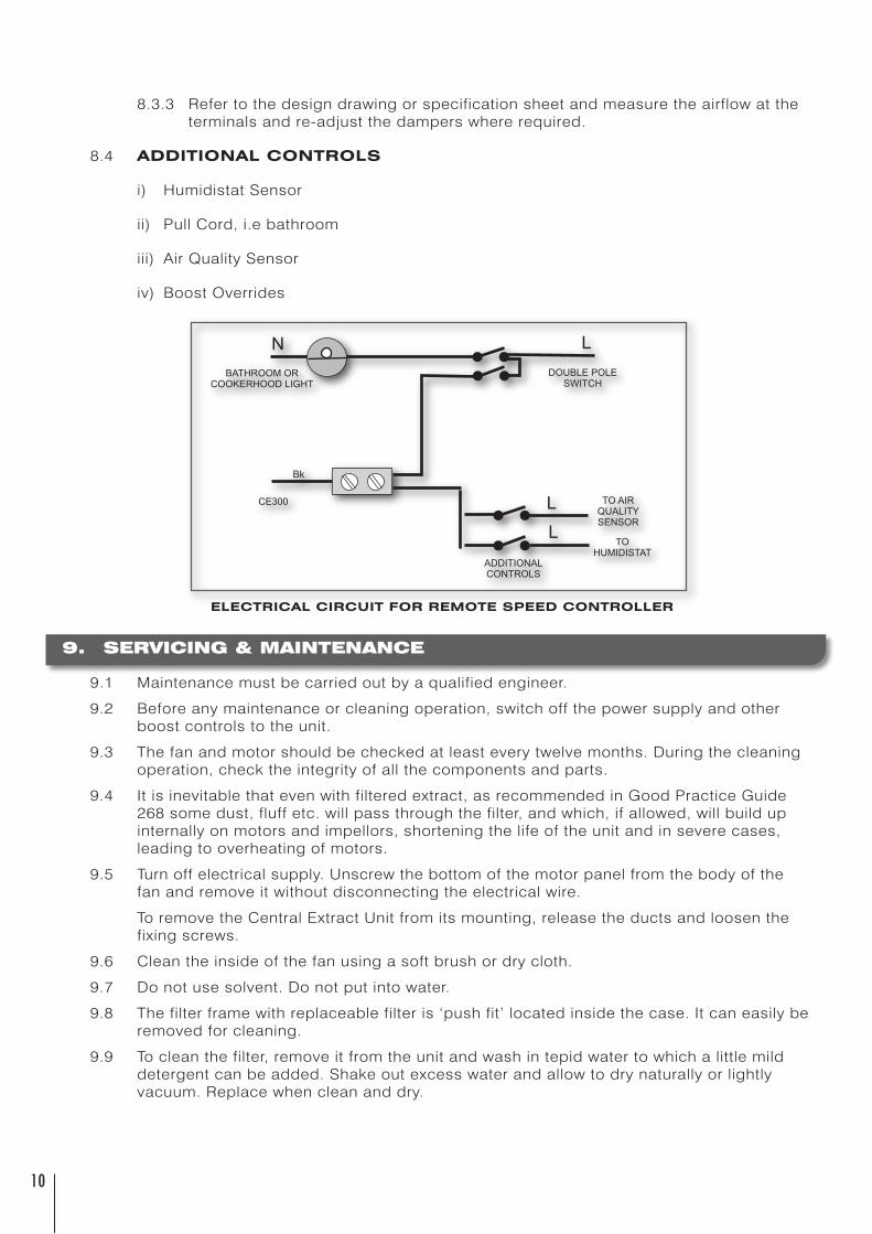
8.4 ADDITIONAL CONTROLS
i) HumidistatSensor
ii) PullCord,i.ebathroom
iii) AirQualitySensor
iv) BoostOverrides
9. SERVICING & MAINTENANCE
9.1 Maintenancemustbecarriedoutbyaqualifiedengineer.
9.2 Beforeanymaintenanceorcleaningoperation,switchoffthepowersupplyandotherboostcontrolstotheunit.
9.3 Thefanandmotorshouldbecheckedatleasteverytwelvemonths.Duringthecleaningoperation,checktheintegrityofallthecomponentsandparts.
9.4 Itisinevitablethatevenwithfilteredextract,asrecommendedinGoodPracticeGuide268somedust,fluffetc.willpassthroughthefilter,andwhich,ifallowed,willbuildupinternallyonmotorsandimpellors,shorteningthelifeoftheunitandinseverecases,leadingtooverheatingofmotors.
9.5 Turnoffelectricalsupply.Unscrewthebottomofthemotorpanelfromthebodyofthefanandremoveitwithoutdisconnectingtheelectricalwire.
ToremovetheCentralExtractUnitfromitsmounting,releasetheductsandloosenthefixingscrews.
9.6 Cleantheinsideofthefanusingasoftbrushordrycloth.
9.7 Donotusesolvent.Donotputintowater.
9.8 Thefilterframewithreplaceablefilteris‘pushfit’locatedinsidethecase.Itcaneasilyberemovedforcleaning.
9.9 Tocleanthefilter,removeitfromtheunitandwashintepidwatertowhichalittlemilddetergentcanbeadded.Shakeoutexcesswaterandallowtodrynaturallyorlightlyvacuum.Replacewhencleananddry.
ELECTRICAL CIRCUIT FOR REMOTE SPEED CONTROLLER

11
11
10. INSTRUCTIONS FOR USER
10.1 INTRODUCTION
TheCE300isaCentralExtractSystemthatextractsstaleorhumidairfromwetrooms,typicallykitchens,bathroomsandutilityroomsandisexhaustedtooutside.Aboostfacilityisprovidedtoenablehigherratesofextractwhenrequired.
ThistypeofsystemcomplieswithApprovedDocumentFoftheBuildingRegulationsF1MeansofVentilation.
InstallationoftheCE300unitwillhavebeencommissionedandbalancedbyacompetentperson.
10.2 USER INSTRUCTIONS
10.2.1 TurnontheCE300applianceatthefusedspur.
10.2.2 TheCE300unitwillnowcommenceextractionattheminimumsetspeed.
10.2.3 TomanuallyboosttheCE300unitwhenrequiredrotatethecontrolknobonthe boostcontrol(A)tothedesiredsetting.Whentheboostisnolongerrequired rotatethecontrolknobtotheoriginalposition.
10.2.4 TheCE300unitmaybefittedwithadditionalremoteautomaticboostswitches thatwillautomaticallyboosttheairflowtoapredeterminedextractrate.
10.2.5 Theperiodoftimethattheunitwillrunatboostspeedwilldependuponthetype ofautomaticboostcontrolfitted.
10.2.6 MaintenanceoftheCE300unitisrequiredannuallytoremoveandcleanfilters andtocleanthefanassembly.
PLEASE NOTE: Orientationofthiscontrolswitchcanbechangedtosuitifrequired.Removethetwo
screwsandre-position.
SPEED CONTROL
A
1�
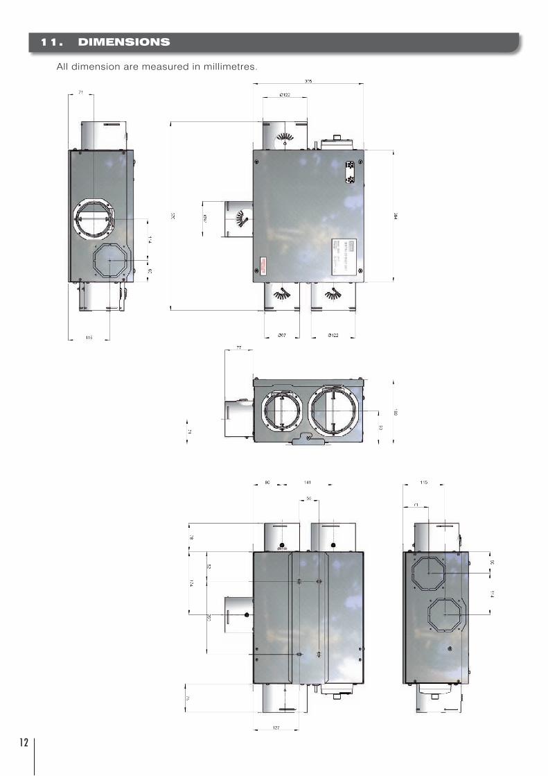
11. DIMENSIONS
Alldimensionaremeasuredinmillimetres.

1�
1�
12. NOTES

1�
13. SPARES LIST
ShouldanyofthecomponentsneedreplacingcontactJohnsonandStarleySparesDepartment.Whenordering,pleasequotetheserialnumberoftheunitandthemodelnumber.
ITEM PART No. DESCRIPTION QTY
1 X300-0110000 CoverAssembly 1
2 X300-0107000 FanScrollAssembly(AC-190) 1
3 1000-0021340 Filters 2
4 X300-0116000 125mmSpigotAssembly 1
5 X300-0115000 100mmSpigotAssembly 3
6 X300-0111000 MountingBracket 1
7 X300-0112000 ElectricalPanelAssembly 1
8 1000-0523580 ControllerAssembly(ACVersion) 1

1�
1�
14. EXPLODED DIAGRAM
ITEM PART No. DESCRIPTION QTY
1 X300-0110000 CoverAssembly 1
2 X300-0107000 FanScrollAssembly(AC-190) 1
3 1000-0021340 Filters 2
4 X300-0116000 125mmSpigotAssembly 1
5 X300-0115000 100mmSpigotAssembly 3
6 X300-0111000 MountingBracket 1
7 X300-0112000 ElectricalPanelAssembly 1
8 1000-0523580 ControllerAssembly(ACVersion) 1
1
2
7
6
8
5
4
3

Johnson & Starley
Johnson&StarleyaretheleadingUK&EuropeanmanufacturersofacompleterangeofDomesticWarmAirHeaters.AlltheheaterssuitbothReplacementandUpgradeneedsandarecompliantwiththenew(2006)amendmentstoPartLoftheBuildingRegulations.
HOME COMFORT SOLUTIONS
Company DetailsWebsiteAddress www.johnsonandstarley.co.uk
Email [email protected]
TelephoneNumber 01604 762881 (Main switchboard)
FaxNumber 01604 767408
SparesTelephone 01604 707012 Fax 01604 762884
SalesTelephone 01604 707012 Fax 01604 764879
ServiceTelephone 01604 707011 Fax 01604 707017
Warm Air Upgrade Enquiry ServiceTelephone 01604 707026 Fax 01604 707017
COMMERCIAL & INDUSTRIAL H&V SOLUTIONS
Company DetailsJohnson & Starley Dravo Division Industrial H&VWebsiteAddress www.dravo.co.uk
Email [email protected]
TelephoneNumber 01604 707022
FaxNumber 01604 706467
RE
NO
BO
ILE
R
RA
NG
E
EC
ON
OM
AIR
EW
AR
MA
IRH
EA
TE
RS
HI-
SP
EC
WA
RM
AIR
H
EA
TE
RS
HE
AT
RE
CO
VE
RY
HO
ME
‘N
’D
RY
VE
NT
ILA
TIO
N
DR
YF
LO
W