centerfire operations manual
TRANSCRIPT

MWD | LWD
CENTERFIRE OPERATIONS MANUAL
REV. 2.6
PART NR. 981021-100-04
- Redefined.

Copyright © 2019 Tensor Drilling Technologies. All Rights Reserved
This document and all information and expression contained herein are the property of TensorDrilling Technologies [Tensor DT] and is provided to the recipient in confidence on a “need toknow” basis. Your use of this document is strictly limited to a legitimate business purposerequiring the information contained herein. Your use of this document constitutes acceptance ofthese terms.
Revision Details
TECHNICAL SERVICES
2418 N Frazier St # 100, Conroe, TX 77303 U.S.A.
Web: www.tensordt.com
Rev # Revision Details Author Approved Date
1.0 New Document E. Campbell C. Chia 30/09/2010
1.1 Correct Figure 4.1 and Data Dump Port diagrams in Sec-tions 4.11.5 and 6.4.7
E. Campbell C. Chia 22/11/2010
1.2 High temperature battery procedures. Added Section 6.4.9. Revised Fig. 1-4 & Tables 2-2, 2-5, 2-6. Additional minor corrections/ revisions.
E. Campbell C. Chia 04/11/2011
1.3 Gamma Module replacement added. E. Campbell C. Chia 11/01/2012
1.4 Included WEEE disposal information in EHS D. Macleod C. Chia 06/06/2012
1.5 Added Section 12.4. Added information on testing of qBUS voltage. Revised Section 8.7.
E. Campbell C. Chia 08/11/2012
1.6 Added use of 2-Bay DM with CTF. E. Campbell C. Chia 08/03/2013
1.7 Added Table 6-1 and Section 4.3.5. Updated Table 2-4, Table 2-6 &Table 4-4. Revised 12.5.
E. Campbell J. Mather 28/03/2014
1.8 Updated Part Numbers. Updated Table 5-1 and 5.2.1. Added details on expectations of data out with measure-ment operating range.
E. Campbell J. Mather 02/07/2014
1.9 Updated Sections 1.5 & Table 4-2. Revised parts lists. E. Campbell J. Mather 08/12/2014
2.0 Added Section 6.2. Updated Sections 1.5, 4.3.4.1 & 10. E. Campbell J. Mather 11/03/2015
2.1 Updated Sections 4.3.4.1, 4.12, 7.3.3 & 12.5.10. Multiple part number updates.
E. Campbell J. Mather 26/06/2015
2.2 Updated Table 4-4. E. Campbell J. Arriaga 09/10/2015
2.3 Updated Sections 4.2.1, 4.5.1, 4.5.2, 4.10, 6.2.2.3 & 7.2.5. Part number updates.
E. Campbell J. Arriaga 23/08/2016
2.4 Updated Table 2-5. Updated 5.2.2 based on updated Ten-sor firmware. Updated 5.2.3. Updated Section 11.2.1. Minor corrections.
E. Campbell J. Arriaga 22/05/2017
2.5 BHGE format E. Campbell J. Arriaga 05/09/2017
2.6 Tensor DT format. E. Campbell M. Mahmood 05/20/2019

Table of Contents
Environment, Health and Safety ........................................................................................... S-1
Important Safety Instructions ................................................................................................ S-1
Waste Electrical and Electronic Equipment [WEEE] Disposal Information ....................... S-2
Icons, Warnings and Notes ..................................................................................................... S-3
SECTION 1 Introduction and System Description ................................................................ 1-11.1 Introduction ........................................................................................................................1-1
1.2 Scope and Layout...............................................................................................................1-1
1.3 Introduction ........................................................................................................................1-2
1.4 Centerfire Components.....................................................................................................1-2
1.5 Data Acquisition .................................................................................................................1-7
1.5.1 Compensation ...........................................................................................................1-7
SECTION 2 System Specifications .......................................................................................... 2-12.1 Introduction ........................................................................................................................2-1
2.2 Sensor Specifications.........................................................................................................2-2
2.3 Environmental Specifications ...........................................................................................2-3
2.4 Mechanical Specifications .................................................................................................2-4
2.5 Weights and Dimensions...................................................................................................2-5
SECTION 3 Quick Guides ......................................................................................................... 3-13.1 Introduction ........................................................................................................................3-1
3.2 Start Up Check List .............................................................................................................3-2
3.3 Logging Check List..............................................................................................................3-3
3.4 End of Run Check List ........................................................................................................3-4
SECTION 4 Test and Verification ............................................................................................ 4-14.1 Introduction ........................................................................................................................4-1
4.2 Storage and Transport.......................................................................................................4-1
4.2.1 Storage at Rigsite ...................................................................................................... 4-14.2.2 Transport ...................................................................................................................4-1
4.3 Battery .................................................................................................................................4-2
4.3.1 Battery Life Calculations ..........................................................................................4-44.3.2 Battery Options .........................................................................................................4-44.3.3 Battery Compatibility ................................................................................................4-54.3.4 Battery Test Procedures ..........................................................................................4-64.3.5 Testing and Storage of Multiple Battery Assemblies ..........................................4-10
4.4 Directional Module...........................................................................................................4-11
4.5 Centerfire Pulser ..............................................................................................................4-14
4.5.1 Pulser Physical Inspection .....................................................................................4-144.5.2 Pulser Electrical Test ...............................................................................................4-154.5.3 Tap Test ....................................................................................................................4-17
CTF_0 REV. 2.6 I

4.5.4 Poppet Tip Installation ........................................................................................... 4-184.6 Centerfire Collar............................................................................................................... 4-20
4.6.1 Physical Inspection ................................................................................................. 4-204.7 Software Installation ....................................................................................................... 4-22
4.7.1 USB Driver Installation ........................................................................................... 4-234.8 Tool Communications ..................................................................................................... 4-24
4.8.1 PC to SAI Communications .................................................................................... 4-244.8.2 SAI to Tool ............................................................................................................... 4-244.8.3 Communication Considerations ........................................................................... 4-24
4.9 Firmware Upgrades ......................................................................................................... 4-25
4.10 Centerfire Communications Test................................................................................. 4-26
4.11 String Test....................................................................................................................... 4-32
4.11.1 Toolstring Assembly Overview ........................................................................... 4-324.11.2 Interconnect Assembly ........................................................................................ 4-334.11.3 Toolstring Connection ......................................................................................... 4-364.11.4 Top Communications .......................................................................................... 4-394.11.5 Dump Port Communications .............................................................................. 4-424.11.6 Tap Test ................................................................................................................. 4-454.11.7 Disassembly .......................................................................................................... 4-45
4.12 Memory Test .................................................................................................................. 4-46
SECTION 5 System Set Up ....................................................................................................... 5-15.1 MWD Toolstring Assembly................................................................................................ 5-1
5.1.1 Centerfire Batteries .................................................................................................. 5-15.1.2 Interconnect Assembly ............................................................................................ 5-15.1.3 Toolstring Connection ............................................................................................. 5-2
5.2 Tool Programming............................................................................................................. 5-5
5.2.1 Nodes ......................................................................................................................... 5-65.2.2 Resistivity Data Sets ................................................................................................. 5-75.2.3 ReSR - Resistivity Status Register ............................................................................ 5-9
5.3 qMWD Configuration Utility ........................................................................................... 5-10
5.3.1 General Setups ....................................................................................................... 5-105.3.2 Telemetry Controls ................................................................................................. 5-145.3.3 Special Telemetry Controls ................................................................................... 5-155.3.4 Mode Control Settings ........................................................................................... 5-165.3.5 Survey Sequence Definitions ................................................................................ 5-175.3.6 Toolface Logging Sequence Definitions .............................................................. 5-185.3.7 Job Site environmental Settings ........................................................................... 5-195.3.8 Directional Processing Controls ........................................................................... 5-205.3.9 Dynamic T/L Sequence Change Controls ............................................................ 5-215.3.10 Battery Processing Controls ............................................................................... 5-225.3.11 Pumps Flow Evaluation Controls ........................................................................ 5-225.3.12 Surface Receiver Controls ................................................................................... 5-23
II REV. 2.6 CTF_0

5.3.13 Depth Tracking Controls ......................................................................................5-235.3.14 PWR Processing Controls .....................................................................................5-245.3.15 Saving Tool Configuration ...................................................................................5-25
5.4 Toolface Set Up.................................................................................................................5-29
5.4.1 MWD Tool Scribing .................................................................................................5-295.5 Battery Jumper Installation .............................................................................................5-30
5.6 Measurement Offsets......................................................................................................5-31
5.6.1 Measurement Datums - Centerfire Tools ............................................................5-325.6.2 Directional Survey Offset. ......................................................................................5-33
SECTION 6 Rig Floor Procedures ............................................................................................ 6-16.1 Introduction ........................................................................................................................6-1
6.2 Weather Extremes..............................................................................................................6-2
6.2.1 Hot Climates ..............................................................................................................6-26.2.2 Cold Climates ............................................................................................................6-2
6.3 Rig Floor Safety...................................................................................................................6-4
6.4 Tool Handling Considerations ..........................................................................................6-6
6.5 Drill Floor Tool Assembly...................................................................................................6-7
6.5.1 Wet Connect Preparation ........................................................................................6-76.5.2 Lift Centerfire to Drillfloor .......................................................................................6-86.5.3 Calculate the Drill Assembly Offset [DAO] .............................................................6-96.5.4 Lift MWD Collar to Drillfloor ..................................................................................6-106.5.5 Insert the MWD String ............................................................................................6-106.5.6 High Temperature Battery Packs ..........................................................................6-136.5.7 Tool Connection Test ..............................................................................................6-146.5.8 Tool Programming ..................................................................................................6-156.5.9 Pre-Run/ Post-Run Calibration Check ...................................................................6-256.5.10 Shallow Hole Test .................................................................................................6-29
SECTION 7 Software Setup ..................................................................................................... 7-17.1 Introduction ........................................................................................................................7-1
7.2 Log Plot Data.......................................................................................................................7-2
7.2.1 Well Data ....................................................................................................................7-27.2.2 BHA Data ....................................................................................................................7-37.2.3 Subs Data ...................................................................................................................7-37.2.4 Mud Data ...................................................................................................................7-47.2.5 Run Data ....................................................................................................................7-57.2.6 Drilling Mode .............................................................................................................7-6
7.3 Data Sets .............................................................................................................................7-7
7.3.1 Memory - Real Time .................................................................................................7-77.3.2 Gamma .......................................................................................................................7-77.3.3 Resistivity ...................................................................................................................7-77.3.4 Conductivity ...............................................................................................................7-8
SECTION 8 Logging ................................................................................................................... 8-18.1 Introduction ........................................................................................................................8-1
CTF_0 REV. 2.6 III

8.1.1 Logging through Casing ........................................................................................... 8-18.1.2 Casing Shoes ............................................................................................................. 8-1
8.2 Normal Logging.................................................................................................................. 8-2
8.2.1 Depth Tracking ......................................................................................................... 8-28.3 Logging Data Continuity.................................................................................................... 8-2
8.4 Logging Data Validity......................................................................................................... 8-3
8.5 Logging Data Presentation ............................................................................................... 8-3
8.6 Notes on the Log Header Information............................................................................ 8-3
8.6.1 Conductivity Meter Conversions ............................................................................ 8-48.7 Repeat Sections.................................................................................................................. 8-4
8.7.1 Relogging ................................................................................................................... 8-48.7.2 Logging Speed .......................................................................................................... 8-5
SECTION 9 Pulling Out ............................................................................................................ 9-19.1 Preparing for Tool Change ............................................................................................... 9-1
9.2 Pulling Out of the Hole...................................................................................................... 9-1
9.2.1 General Considerations ........................................................................................... 9-19.2.2 Downloading the Centerfire Memory .................................................................... 9-19.2.3 Log Copies ................................................................................................................. 9-29.2.4 Post-Run Calibration Check ..................................................................................... 9-2
9.3 Racking-back....................................................................................................................... 9-3
9.3.1 Introduction .............................................................................................................. 9-39.4 Laying Down the Centerfire.............................................................................................. 9-4
9.4.1 Laying Down the MWD Tool .................................................................................... 9-49.5 Equipment Levels .............................................................................................................. 9-4
9.6 Battery Calculations........................................................................................................... 9-4
9.7 Conclusion of Operations ................................................................................................. 9-5
SECTION 10 Troubleshooting ............................................................................................... 10-110.1 Introduction.................................................................................................................... 10-1
SECTION 11 Parts Lists .......................................................................................................... 11-111.1 Introduction.................................................................................................................... 11-1
11.2 Downhole Equipment ................................................................................................... 11-2
11.2.1 MWD/LWD Downhole Equipment 175ºC, Centerfire (RS-411389) ................. 11-211.2.2 Battery Cartridges ................................................................................................ 11-211.2.3 4.75” Centerfire Assembly ................................................................................... 11-211.2.4 6.91” Centerfire Assembly ................................................................................... 11-211.2.5 8.25” Centerfire Assembly ................................................................................... 11-2
11.3 Surface Equipment ........................................................................................................ 11-3
11.3.1 Surface System Support Kit, Centerfire (460006G002) .................................... 11-311.3.2 KIT, MWD Depth Tracking Option (985006G006) ............................................. 11-311.3.3 Retrieval Equipment Kit (460008G001) .............................................................. 11-4
IV REV. 2.6 CTF_0

11.3.4 Hand Tool Kit (460009G001) ...............................................................................11-411.4 Spares and Consumables .............................................................................................11-5
11.4.1 Spare Parts ............................................................................................................11-511.4.2 Consumables .........................................................................................................11-5
SECTION 12 Appendix ........................................................................................................... 12-112.1 General Battery Handling and Safety ..........................................................................12-1
12.1.1 Introduction ...........................................................................................................12-112.1.2 Battery Composition ............................................................................................12-112.1.3 Workshop Practices ..............................................................................................12-212.1.4 Overheating or self-heating: ...............................................................................12-212.1.5 Damaged Power Sections: ...................................................................................12-212.1.6 Battery Storage .....................................................................................................12-312.1.7 Battery Shipping and Disposal ............................................................................12-3
12.2 Safe Handling of Equipment Damaged by Battery Pack Venting.............................12-4
12.2.1 Damage Products and Hazards Associated with Battery Venting ..................12-412.2.2 Battery Venting at the Wellsite - Identification .................................................12-512.2.3 Identifying a Battery Venting Incident is not always easy ...............................12-512.2.4 Dismantling the Equipment ................................................................................12-612.2.5 What can be Salvaged? ........................................................................................12-712.2.6 Conclusions ...........................................................................................................12-7
12.3 Material Safety Data Sheets..........................................................................................12-8
12.3.1 Chemicals used during Battery Module Maintenance .....................................12-812.3.2 Lithium Thionyl Chloride Batteries .....................................................................12-9
12.4 Management of Trapped Pressure............................................................................12-14
12.4.1 Trapped Pressure Safety ...................................................................................12-1512.5 Tool Programming Reference.....................................................................................12-16
12.5.1 Data Sequence - Measurement Components .................................................12-1612.5.2 Node Address ......................................................................................................12-1612.5.3 Data Variables- Survey Sequences ...................................................................12-1712.5.4 Data Variables - Toolface/ Logging Sequence .................................................12-1712.5.5 ReNF and ReSR ....................................................................................................12-1812.5.6 Data Resolution - General .................................................................................12-2012.5.7 Data Resolution - Phase Difference and Attenuation ....................................12-2112.5.8 Error Detection ...................................................................................................12-2212.5.9 Data Sampling .....................................................................................................12-2212.5.10 Repeat Loops ....................................................................................................12-2212.5.11 Packed Data Sets ..............................................................................................12-2312.5.12 Grouping ............................................................................................................12-2312.5.13 Special Controls ................................................................................................12-23
12.6 Gamma Module Replacement....................................................................................12-24
12.6.1 Gamma Module Removal ..................................................................................12-2412.6.2 Gamma Module Attachment .............................................................................12-2412.6.3 Gamma Collar Connection ................................................................................12-25
CTF_0 REV. 2.6 V

THIS PAGE INTENTIONALLY LEFT BLANK
VI REV. 2.6 CTF_0

Environment, Health and Safety
Important Safety Instructions
Read all of these instructions before working with the Centerfire LWD Assembly.
• Do not attempt to service the Centerfire or any of its sub-assemblies unless the appropriate training has been given by a Tensor DT-authorised trainer.
• Wear appropriate personal protective equipment when working on the Centerfire; gloves, coveralls, steel-toed boots and safety glasses should be considered a minimum requirement.
• Storage of Battery Packs and spare Battery Cartridges at the rigsite should be carefully considered; the site chosen should be:• inside protected from rain/ moisture, preferably in the battery shipping crates in
vermiculite• in a stable temperature ~10ºC - 25ºC• isolated from day to day operations• well ventilated
• Always use the correct tool for the job.
• When handling or lifting any part of the Centerfire system appropriate manual handling procedures should be followed. Weights and dimensions of all assemblies can be found in Table 2-6, “Weights and Dimensions”.
• Operation and maintenance of the system may result in exposure to potentially harmful drilling fluids. Details of the fluid should be available and required precautions taken to ensure the safety of all personnel.
• Operators must be aware of the extremes of temperature that can exist with the assemblies and so proper PPE should be worn when handling the tools. Tools that have been run downhole can become extremely hot while those that have been left in the open can become either very hot or very cold.
• Material Safety Data Sheets [MSDS] for all approved substances, including batteries, used with the Centerfire must be available to the operator. Refer to Section 12.3 for information on MSDS. Operators must access and reference MSDS for any other substances that are used during the operation of the Centerfire system.
NOTE: Any tool section could contain trapped pressure. Refer to Section 12.4, “Management of Trapped Pressure” for information on recognising and dealing with trapped pressure.
NOTE: Any processing of Beryllium Copper [BeCu] that could produce airborne dust or fumes [such as dry grinding, filing, or any kind of abrading] should be regarded as hazardous and personnel should take appropriate precau-tions. A face mask and safety goggles should be considered mandatory (refer to the information in Section 12.3 for further details).
NOTE: NEVER use heat or force when dealing with Lithium Thionyl Chloride bat-teries; refer to Section 12.2 for procedures to follow in the event of battery problems.
CTF_0 REV. 2.6 S-1

Waste Electrical and Electronic Equipment [WEEE] Disposal Information
ELECTRICAL EQUIPMENT DISPOSAL
Electrical equipment must be disposed of in accordance with any Local/ Interna-tional Rules and Regulations for the collection framework available to customers for the return, recycling and treatment of electrical wire and components.
For more information refer to: http://www.weeerohsinfo.com/
BATTERY DISPOSAL
The disposal of batteries must comply with Local/ International Rules and Regula-tions. They will recommend the collection framework available to return, recycle and treatment of batteries. These precautions are important and necessary to minimise the negative effects of batteries to the environment and to sustain available natural resources.
For more information refer to: http://www.weeerohsinfo.com/
S-2 REV. 2.6 CTF_0

Icons, Warnings and Notes
Use of these warning symbols indicate the following:
This symbol indicates as warning, caution or potential safety hazard to the user. The precise na-ture of the hazard will be explained in the text.
Protective eyewear must be worn at all times
Ear protection must be worn at all times
Protective headwear must be worn at all times
Protective clothing must be worn at all times
Protective footwear must be worn at all times
Breathing apparatus must be worn at all times
Hand protection must be worn at all times
Possible risk of explosion
CTF_0 REV. 2.6 S-3

THIS PAGE INTENTIONALLY LEFT BLANK
S-4 REV. 2.6 CTF_0

CHAPTER
INTRODUCTION AND SYSTEM DESCRIPTION
1.1 Introduction
This publication is intended as a reference text for those involved in the operation of theCenterfire LWD Tool.
The Centerfire Tool provides state-of-the-art Resistivity and Gamma measurements whiledrilling. Resistivity measurements are compensated for errors due to rugosity in theborehole (“caves” or “washouts”) and also for errors due to temperature drifts in theelectronics. The Gamma tool is connected below the Resistivity collar in the 4.75” and 6.91”tools or is integrated within the main 8.25” collar.
NOTE: Maintenance of the Centerfire tool is covered by the Centerfire Maintenance Man-ual (981020-100-06).
1.2 Scope and Layout
The scope of this manual covers all operational procedures required to ensure the Centerfiretool consistently delivers accurate data and to maximise the effective life of the systems.
The broad outline of the manual is as follows:
• System description
• System specifications
• System test and set-up
• Rig Floor Procedures
• Software
• Logging
• Reference section (parts lists, appendix)
NOTE: This manual concentrates on Centerfire tool operations; for informationon operation of the Tensor MWD equipment, consult the relevant opera-tions manual for the component of interest.
CTF_0 REV. 2.6 1-1

CHAPTER 1 INTRODUCTION AND SYSTEM DESCRIPTION
1.3 Introduction
The Centerfire Resistivity tool has two receivers and four transmitters giving two T-R spacings(19" and 41") providing two different phase-derived resistivity measurements at two depthsof investigation. In addition, measurements are taken at two frequencies to provide a total offour phase derived resistivity measurements at four depths of investigation. The four depthsof investigation together with the high accuracy and high vertical resolution phasedifference-based measurements ensure a comprehensive and accurate evaluation of theformation resistivity. In addition to the four phase derived resistivities, the Centerfire systemalso provides four attenuation based resistivities (two spacings, two frequencies). Theattenuation resistivities provide deeper depths of investigation than the phase differenceresistivities, but are limited to lower resistivity formations with reduced accuracy and verticalresolution.
The Centerfire tool is available in three standard sizes - 4.75”, 6.91” and 8.25” (120.7mm,175.5mm, 209.6mm).
The Antenna Array consists of six antennas – a pair of receivers at the centre of the tool andpairs of transmitters above and below the receivers. The electronics for the receivers arelocated either side of the receiver antennas, and electronics for the transmitters are locatedbetween both pairs of transmitters. Memory Recorder and DSP/ Power Supply boards arelocated between the uphole transmitters. All electronic boards are located beneath sealedremovable plates.
8.25” tools have two internal Gamma Sensors located at the bottom of the tool. Thesereplace the standard Tensor Gamma Ray tool which is used with the smaller Centerfire tools.
1.4 Centerfire Components
The Centerfire system has the following components:
• Transmitters - Produce electromagnetic waves at two frequencies (400kHz and 2MHz) that travel through the formation to the Receivers.
• Receivers - Detect the electromagnetic waves produced by the Transmitters.
• DSP/ Power Supply Board - regulates power for the Centerfire systems and processes the signal from the receiver coils.
• Memory Board - 14Mb memory has 294 hours of recording capacity at a 10 second update rate. Records both Resistivity and Gamma data. Once the memory is full the recording stops.
• Communications Port - Connects to the Safe Area Interface [SAI] by way of the POD Cable to allow PC communications during tool set up, test and memory download.
• Wet Connect - A male/ female connector assembly on top of the Centerfire tool and on the bottom of the MWD tool allows power transfer from the batteries to the Centerfire tool (including the Gamma sensor on the bottom) and Resistivity data transfer from the Centerfire tool to the Directional Module [DM]. Data transferred from the Centerfire is transmitted to the surface by the MWD tool.
• Gamma Centralizer - Located in the bottom of the Centerfire collar allowing a Gamma Ray tool to be connected to the Centerfire.1 The Gamma Tool is then housed in its own short non-magnetic drill collar.
1. The Centerfire Gamma module is a modified standard Gamma module. Centerfire tools come with theGamma module already converted.
1-2 REV. 2.6 CTF_0

CHAPTER 1 INTRODUCTION AND SYSTEM DESCRIPTION
• Gamma Sensors measure the naturally occurring radiation in the rock:-• 4.75” and 6.91” tools have a Gamma module connected to the Gamma Centralizer
below the Resistivity collar. Standard Tensor Gamma modules are modified for use with the Centerfire system by way of the Gamma Conversion Kit which changes the upper connector from a standard 10 pin Kintec connecter to the 7 ring rotary connector.
• 8.25” tools have two collar-mounted gamma sensors, 180° apart in the resistivity collar.
• Batteries:-• Standard (150°) or High Temperature (180°) batteries can be used.• The recommendation is three batteries; two batteries can be used but the battery
life can be reduced by approximately 33%. This figure is for the Standard (150°C/ 304°F) batteries.
• Never mix new and used batteries; the batteries are connected in parallel and power is taken from all three (or two) all the time.
• Never mix Standard and High Temperature batteries.• Never mix batteries from different manufacturers.• It is recommended that two-battery runs last for less than 150 hours.• The battery life depends on a number of factors including the operating and storage
history and temperature so these must be monitored closely.• Always keep a record of battery usage and write on the cartridges pertinent
information such as new or used, estimated life remaining, battery position (1,2 or 3), maximum temperature.
CTF_0 REV. 2.6 1-3

CHAPTER 1 INTRODUCTION AND SYSTEM DESCRIPTION
Figure 1-1 Centerfire Tool (4.75”)
1 Wet Connect Anchor Bolts 6 Transmitter Board 11 Lower Receiver
2 Muleshoe Anchor Bolts 7 Recorder Board 12 Receiver Board
3 Data Dump Port 8 Upper Short Transmitter 13 Lower Short Transmitter
4 Upper Long Transmitter 9 Receiver Board 14 Transmitter Board
5 DSP Board 10 Upper Receiver 15 Lower Long Transmitter
1
6
7
8
9
10
11
14
13
12
4
3
2
15
5
1-4 REV. 2.6 CTF_0

CHAPTER 1 INTRODUCTION AND SYSTEM DESCRIPTION
Figure 1-2 Centerfire Tool (6.91”)
1 Wet Connect Anchor Bolts 7 DSP Board 13 Lower Short Transmitter
2 Muleshoe Anchor Bolts 8 Upper Short Transmitter 14 Transmitter Board
3 Data Dump Port 9 Receiver Board 15 Lower Long Transmitter
4 Upper Long Transmitter 10 Upper Receiver 16 Gamma Centralizer Cover
5 Recorder Board 11 Lower Receiver
6 Transmitter Board 12 Receiver Board
1
6
7
8
9
10
11
14
13
12
4
3
2
15
5
16
CTF_0 REV. 2.6 1-5

CHAPTER 1 INTRODUCTION AND SYSTEM DESCRIPTION
Figure 1-3 Centerfire Tool (8.25”)
1 Wet Connect Anchor Bolts 7 Recorder Board 13 Lower Short Transmitter
2 Muleshoe Anchor Bolts 8 Upper Short Transmitter 14 Transmitter Board
3 Data Dump Port 9 Receiver Board 15 Lower Long Transmitter
4 Upper Long Transmitter 10 Upper Receiver 16 Gamma Sensor
5 DSP Board 11 Lower Receiver 17 Gamma Sensor
6 Transmitter Board 12 Receiver Board 18 Gamma Centralizer Cover
1
6
7
8
9
10
11
14
13
12
4
3
2
15
5
16
17
18
1-6 REV. 2.6 CTF_0

CHAPTER 1 INTRODUCTION AND SYSTEM DESCRIPTION
1.5 Data Acquisition
The Centerfire receivers measure phase and amplitude of a known signal, which originates atthe Centerfire transmitters, to determine formation resistivity.
NOTE: Resistivity increases as both phase difference and attenuation decrease and as aresult an inverse relationship will be seen if resistivity is plotted together witheither phase difference or attenuation.
Phase and amplitude data is collected in each of the eight acquisition steps in the Centerfireacquisition cycle. The cycle is designed to optimise borehole compensation by reducing thetime, and so possible depth change, between corresponding sets of data used in thecompensation calculation.
The eight measurement steps in the Centerfire acquisition cycle are:-
Table 1-1 Centerfire Measurement Sequence
At the end of the acquisition cycle there is an optional ‘Dead Time’ which can be enabledwhen setting up the tool. This delay period sets the time between the end of one acquisitioncycle and the start of the next. The Dead Time setting can be used to conserve memory andpower at low rates of penetration [ROP].
1.5.1 Compensation
From the eight measurements in the acquisition cycle the Centerfire tool generates four setsof compensated phase difference data and four sets of compensated attenuation data.
To achieve compensated measurements the Centerfire tool averages the measurementsfrom the Upper and Lower Transmitters. Figure 1-4 shows the calculation of long and shortspaced phase difference data at a single frequency.
Measure-ment
TransmitterFrequency
Number Lower/ Upper Short/ Long
1 3 Lower Short 400 kHz
2 4 Upper Short 400 kHz
3 1 Lower Long 400 kHz
4 2 Upper Long 400 kHz
5 3 Lower Short 2 MHz
6 4 Upper Short 2 MHz
7 1 Lower Long 2 MHz
8 2 Upper Long 2 MHz
CTF_0 REV. 2.6 1-7

CHAPTER 1 INTRODUCTION AND SYSTEM DESCRIPTION
Figure 1-4 Centerfire Compensated Tool
TRX 2
TRX =TransmitterRX = Receiver
PD = Phase Difference
P22 P21
P42P41
P11P31
P12P32
P1 (Lower PD 41”) = P12-P11P2 (Upper PD 41”) = P21-P22P3 (Lower PD 19”) = P32-P31P4 (Upper PD 19”) = P41-P42
Compensated PD 41” = (P1 + P2) / 2
Compensated PD 19” = (P3 + P4) / 2
TRX 4
RX 2
RX 1
TRX 3
TRX 1
1-8 REV. 2.6 CTF_0

CHAPTER
SYSTEM SPECIFICATIONS
2.1 Introduction
This section deals with Sensor Specifications, Mechanical & Environmental Specifications andGeneral Information useful to all field and base staff.
NOTE: THE OPERATING SPECIFICATIONS HAVE BEEN VERY CAREFULLY CALCULATED TOALLOW THE CENTERFIRE CUSTOMER TO GET THE BEST USE OUT OF THE EQUIPMENT.TENSOR DT CANNOT BE HELD RESPONSIBLE FOR PROBLEMS WITH THE EQUIPMENTIF IT IS NOT USED WITHIN THE LIMITS DEFINED IN THIS SECTION.
Due to continuous product improvement Tensor DT reserves the right to change thesespecifications without prior notice.
CTF_0 REV. 2.6 2-1

CHAPTER 2 SYSTEM SPECIFICATIONS
2.2 Sensor Specifications
Table 2-1 Resistivity Tool Specifications
Table 2-2 Resistivity Sensor Specifications
Parameter
Memory 14Mb Internal (memory also recorded in MWD Directional Module)
Memory Record Size 134 bytes
Memory Capacity 109552 records (290 hrs @ 10 second sampling)
Real Time Update rate 3.6 samples/ft at 50 ft/hr (0.5s pulse width, standard telemetry sequence, rotating)
Minimum Sampling Period
10 seconds MWD Mode (1.2 seconds Trip Out Mode)
Power 2 or 3 x Lithium Thionyl Chloride Battery ModulesMinimum 160 hrs @ 0.5 second pulse width(3 batteries)
Parameter Spacing Frequency Range1
1. Data is unreliable, and may not compare with other data sets, when outside the Operating Range.
Accuracy
Phase Differ-ence
41” (1041 mm)
2 MHz0.1 - 2000 ohm.m
+/- 2% (0.1-20 ohm.m) +/- 1 mmho/m (>20 ohm.m)
400 kHz 0.1 - 500 ohm.m
+/- 2% (0.1-10 ohm.m) +/- 2 mmho/m (>10 ohm.m)
19” (483 mm)
2 MHz0.1 - 1000 ohm.m
+/- 1% (0.1-10 ohm.m) +/- 1 mmho/m (>10 ohm.m)
400 kHz 0.1 - 250 ohm.m
+/- 3% (0.1-5 ohm.m) +/- 6 mmho/m (>5 ohm.m)
Attenuation
41” (1041 mm)
2 MHz 0.1 - 50 ohm.m
+/- 5% (0.1-16 ohm.m) +/- 3 mmho/m (>16 ohm.m)
400 kHz 0.1 - 10 ohm.m
+/- 3% (0.1-3 ohm.m) +/- 10 mmho/m (>3 ohm.m)
19” (483 mm)
2 MHz 0.1 - 50 ohm.m
+/- 5% (0.1-8 ohm.m) +/- 6 mmho/m (>8 ohm.m)
400 kHz 0.1 -10 ohm.m
+/- 5% (0.1-3 ohm.m) +/- 15 mmho/m (>3 ohm.m)
Vertical Reso-lution2
2. In conductive beds <10 ohm.m
6” (152 mm)
2-2 REV. 2.6 CTF_0

CHAPTER 2 SYSTEM SPECIFICATIONS
Table 2-3 Gamma Ray Tool Specifications
2.3 Environmental Specifications
Table 2-4 Environmental Specifications
Parameter
Memory Update rate 7.2 samples/ft at 50 ft/hr
Real Time Update rate 3.6 samples/ft at 50 ft/hr (rotating); 2.4 samples/ft at 50 ft/hr (slid-ing)
Gamma Ray Resolution 1 API
Gamma Ray Sensitivity 2.5 counts/API with housing
Memory 16 Mb (memory in MWD Directional Module and Centerfire tool)
Minimum Sampling Period
Programmable 1-60 seconds (memory every 1 second, telemetry every 2 seconds)
Memory Capacity See resistivity memory capacity
Parameter Specification Comments
Pressure Limit1
1. Hydrostatic pressure + differential pressure
20,000 psi [1380 bar, 138 MPa]
The Centerfire Female Wet Connect cannot withstand pressure unless it is isolated by hav-ing the Male Wet Connect correctly seated.
Temperature Limit[Standard Batteries]
0°C - 150°C [32°F - 302°F]
Never mix Standard and High Temperature Bat-teries in the same string
Temperature Limit[High Temperature Batteries]
100°C - 175°C [302°F - 347°F]
Never mix Standard and High Temperature Bat-teries in the same string
Shock Limit 1000 g/ 0.5 ms
Vibration Limits 20 g RMS
Mud Sand Content <1.0%At Maximum Continuous Flow [MCF] for the drill collar I.D. Higher sand content tolerable if mud flow is reduced
Lost Circulation Mate-rial [LCM] Limit
40 - 50 lb/ bbl medium nut plug
Must be EVENLY mixed into mud system or pre-mixed
Mud Weight No known limit Using conventional mud chemicals & weighting agents and mud mixed evenlyMud Solids No known limit
Mud Viscosity No known limit
CTF_0 REV. 2.6 2-3

CHAPTER 2:
2-4
2.4Table 2-5 Mechanical Specifications - Centerfire Tools
Equivalent Bending
Flow Rate (water)1
Tool COLLAR O.D.COLLAR I.D.
WEARBAND O.D.
Tool Joints
Recommended Make-up
SYSTEM SPECIFICATIO
NS
Mechanical Specifications
Stiffness
in4 US GPM l/s
21.2 200-350 12.6-22.1
43.0 300-750 18.9-47.3
164.0 450-1200 28.4-75.7
LS]
REV. 2.6CTF_0
Torque
1. Mud sand content must be <1.0% for continuous operation at Maximum Continuous Flow.
in. mm in. mm in. mm lbf.ft kgf.m
4.75 5.00 127 1.5 38.1 5.25 133.4 3-1/2” I.F. 9600 1327
6.91 6.91 175.5 2.81 71.4 7.16 181.8 4 -1/2” I.F. 24000 3318
8.25 8.25 209.6 2.81 71.4 8.50 215.9 6-5/8” REG 46000 6360
COLLAR O.D. COLLAR I.D. Tool Joints Maximum Dogleg Severity [D
in. mm in. mm deg/ ft. Sliding & Rotating2
2. Figures based on typical drill collar configurations.
4.75 5.00 127 1.5 38.1 3-1/2” I.F. 0.25/ 0.12
6.91 6.91 175.5 2.81 71.4 4-1/2” I.F. 0.17/ 0.08
8.25 8.25 209.6 2.81 71.4 6-5/8” REG 0.14/ 0.07

CHAPTER 2 SYSTEM SPECIFICATIONS
2.5 Weights and Dimensions
Table 2-6 Weights and Dimensions
Equipment Dimensions (in/ mm) Weight (lb/ kg)TOOLS Max Diam-
eterLength Width Height
Pulser 1.875/ 47.6 102.75/ 2610 - - 36.38/ 16.5Battery Module 1.875/ 47.6 70/ 1778 - - 22.0/ 10.0Directional Module (2-bay) 1.875/ 47.6 79.80/ 2026 - - 17.25/ 7.8Directional Module (3-bay) 1.875/ 47.6 89.75/ 2280 - - 20.00/ 9.1Gamma Module 1.875/ 47.6 59.5/ 1511 - - 15/ 6.8Interconnect 1.875/ 47.6 14.06/ 35.71 - - 8.82/ 4.0
Centerfire Collars BORE 4.75” [121 mm] 5.25/ 133 174/ 44201 3.128/ 79.5 830/ 3776.91” [175.5 mm] 7.16/ 182 174/ 4420 3.750/ 95 1675/ 7618.25” [203 mm] 8.5/ 216 182/ 4621 3.750/ 95 2050/ 2932Gamma Collars4.75” [121 mm] 4.75/ 121 99.80/ 2535 2.8125/ 71.4 329/ 149.46.75” [171 mm] 6.75/ 171 99.25/ 2521 3.25/ 82.6 773/ 350.8
1. This is the shoulder-to-shoulder dimension for box-box subs.
CTF_0 REV. 2.6 2-5

CHAPTER 2: SYSTEM SPECIFICATIONS
THIS PAGE INTENTIONALLY LEFT BLANK
2-6 REV. 2.6 CTF_0

CHAPTER
QUICK GUIDES
3.1 Introduction
This section provides checklists to be used when operating the Centerfire system. At everystep reference should be made to the appropriate sections in this manual or referencedmanuals to ensure correct procedures are followed.
CTF_0 REV. 2.6 3-1

CHAPTER 3 QUICK GUIDES
3.2 Start Up Check List
Step Procedure Section Other Manual Notes
1 Rig Up Surface Equip-ment
4.7 Surface System Operator Man-ual
Install latest software, calibrate sen-sors, update SAI firmware
2 Deck Test MWD String Modules
4.3, 4.4, 4.5, 4.9
Update firmware if necessary
3 Calculate Battery Life 4.3.1
4 Select Poppet Tip 4.5.4
5 Deck Test Centerfire 4.6 Check latest firmware is installed
6 Create Configuration 5.2 MWD Operator Manual
Confirm with customer
7 Assemble MWD String
5.1 3 x Battery Modules. Install all Inter-connects first. Assemble string so last connection powers the string.
8 Program MWD String 5.2 MWD Operator Manual
9 Set MWD Internal Toolface
5.4 MWD Operator Manual
10 Scribe MWD High Side
5.4.1
11 Pick Up Centerfire 6.5.2
12 Pick Up MWD Col-lar(s)
6.5.4
13 Scribe BHA, Calcu-late DAO
6.5.4 Confirm with Directional Driller. Enter in qMWD Configuration.
14 Insert MWD 6.5.5
15 Check Centerfire Voltage
6.5.7
16 Program Centerfire 6.5.8.2
17 Set System Time 6.5.8.4
18 Clear Memory 6.5.8.5
19 Pre-run Calibration Check
6.5.9
20 Shallow Hole Test 6.5.10 Configure qMWD to detect
3-2 REV. 2.6 CTF_0

CHAPTER 3 QUICK GUIDES
3.3 Logging Check List
Step Procedure Section Other Manual Notes
1 Create LogView II Toolrun
7.2 LogView II Oper-ator Manual
Collar sizes, hole size, calibrations
2 Confirm Start Depth MWD Operator Manual
3 Input Mud Data 7.2.4 < every 12 hours.
4 Verify Depth Track-ing Accuracy
MWD Operator Manual / Sur-face System Operator Man-ual
Every connection
5 Verify Tool Response 8.3, 8.4 Resistivity Prin-ciples Manual
Offset logs, geologist
6 Monitor Battery Usage
4.3.1
7 Prepare Logs 7.3, 8.5, 8.6 LogView II Oper-ator Manual
Agree format with customer
CTF_0 REV. 2.6 3-3

CHAPTER 3 QUICK GUIDES
3.4 End of Run Check List
Step Procedure Section Other Manual Notes
1 Confirm End Depth 7.2.4 MWD Operator Manual
2 Prepare Logs 7.3, 8.5, 8.6 LogView II Oper-ator Manual
Agree format with customer
3 Calculate Battery Life 4.3.1 Resistivity Prin-ciples Manual
May require replacement of MWD string
4 Confirm Next Run Plan, Create Configu-ration
5.2 MWD Operator Manual
Duration, objectives. Confirm with customer.
5 Download Memory 9.2.2 Centerfire, Directional Module
6 Verify Tool Memory 8.3, 8.4 Resistivity Prin-ciples Manual
Offset logs, geologist
7 Post-run Calibration Check
6.5.9
8 Clear Memory 6.5.8.5
3-4 REV. 2.6 CTF_0

CHAPTER
TEST AND VERIFICATION
4.1 Introduction
When a Centerfire tool is received at the rigsite it must be given a thorough inspection andtest before being used downhole.
4.2 Storage and Transport
4.2.1 Storage at Rigsite
Store the Centerfire tools as follows:-
• under cover
• off the ground on suitable racks which are secured to the floor
• preferably in an enclosed area
• protect the antennae
• always fit thread protectors
• cover the muleshoe anchor bolt holes with waterproof tape to reduce the chance of corrosion
• do not stack mud motors, or any other equipment with upsets which could damage the antennae, on top of the tools
NOTE: Refer to Section 6.2 for details of tool storage in extreme temperatures.
NOTE: It is recommended that all O-rings should be replaced if a tool is not used for aperiod of 3 months or longer. Where a period of inactivity is anticipated, it may bebeneficial to remove all seals from the tools until they are to be used again.
4.2.2 Transport
Transport the tools as follows:-
• in cargo baskets or
• loose/ individually - secured firmly to stop them rolling and/or sliding
• protect the antennae
NOTE: Extra care should be taken during transportation to ensure the antennae are notsubjected to impacts.
CTF_0 REV. 2.6 4-1

CHAPTER 4 TEST AND VERIFICATION
4.3 Battery
When running Centerfire tools it is strongly recommended that three battery packs are usedto power the string - this is the standard configuration. The operator must be aware thatwhen running three battery packs they must be positioned above the Directional Module andthe Battery Jumper (981524) must be used on the top Battery Module.
Exceeding the maximum current limit of Lithium Chloride batteries reduces the ratedcapacity of the batteries. When running the Centerfire tool with a gamma sensor and anMWD string the current draw will exceed the maximum current limit of a single battery.Therefore, to maximise the life of batteries it is essential that at least two batteries arerun together in parallel (using the Battery Jumper) to ensure the effective current drawon each battery pack remains below the maximum current draw to allow the quoted batterycapacity to be achieved.
NOTE: Using a single battery, or two batteries in series (not using a Battery Jumper) willresult in greatly reduced battery life.
NOTE: Using three batteries without the Battery Jumper will result in one battery power-ing the entire string before its depletion results in the other two batteries switch-ing on. Again this set up will result in greatly reduced battery life.
The MWD string will extend up to 37.4” (11.4 m) from the Centerfire Collar as a result of usingthree battery packs and so the operator must ensure the non-magnetic drill collar in whichthe tool is to be run is long enough. A short non-magnetic pony collar can be added if thenon-magnetic MWD drill collar is not long enough.
4-2 REV. 2.6 CTF_0

CHAPTER 4 TEST AND VERIFICATION
Figure 4-1 Tensor String for use with Centerfire
Battery
Battery
Battery
3 Bay Directional Module
Pulser
Spear Point
Battery Jumper (981524) must be used
Centerfire Collar
37.4’11.4 m
2 Bay Directional Module
36.6’11.1 m
CTF_0 REV. 2.6 4-3

CHAPTER 4 TEST AND VERIFICATION
4.3.1 Battery Life Calculations
To determine how long a set of batteries will effectively power the Centerfire system anumber of variables have to be considered. These include:
• Pulse Width
• Transmission Configuration
• Centerfire Dead Time
• Survey Sample Time
• Battery Rating (from manufacturer)
• Temperature of Operation
To allow the expected battery life to be estimated a calculator spreadsheet is available fordownload from Tensor Technical Support website at www.tensordt.com. Access to the siterequires registration. Contact the Regional Support Centre for details on registration.
NOTE: The spreadsheet is only to be used as a guide and operators must determine theactual expected life of their batteries based on operating conditions.
As an approximate estimate of battery life with various set ups refer to Table 4-1. Thebattery life displayed is based on new standard temperature Spectrum Inc. batteries beingrun in parallel (using the Battery Jumper).
Table 4-1 Approximate Minimum Battery Life
4.3.2 Battery Options
Centerfire tools are powered from battery packs that are part of the Tensor MWD string.Resistivity tools require THREE NEW Lithium battery packs. Battery Packs have 8 x DD size,Dual Anode, LiCl cells. Packs are manufactured by Spectrum Batteries Inc (http://www.spectrumbatteries.com/) and contain cells manufactured by Engineered Power (http://www.engineeredpower.com/products/). Customers who use batteries not produced bySpectrum Batteries Inc. do so at their own risk and must develop operational guidelinesbased on advice from the manufacturer.
Part numbers quoted in this document are those of the manufacturer and take the form:
AABBCCCDDEEFGHI
Where
A = Probe Manufacturer (Tensor) B = Cell Supplier (BE = Engineered Power)C = Maximum Operating Temperature D = Cell QuantityE = Cell Size F = Primary or SecondaryG = Type (D = Dual Anode) H = Cathode (L = Liquid)I = Drawing Number Revision
Pulse Width 2 Batteries 3 Batteries
0.5 Sec 110 160 hrs
1.0 Sec 145 220 hrs
2.0 Sec 170 260 hrs
4-4 REV. 2.6 CTF_0

CHAPTER 4 TEST AND VERIFICATION
Two types of battery pack are available for use with the Centerfire System:
• Low Temperature Battery - TIBE150082DPDL2These batteries have an operating range of -40ºC / -40ºF to 150ºC / 302ºF. Operating thebatteries under the minimum or over the maximum temperatures could cause tool failureand/ or catastrophic failure of the battery itself.
• High Temperature Battery - TIBE180082DPDL2These batteries have an operating range of 100ºC / 212ºF to 180ºC / 356ºF. Exceeding themaximum operating temperature could cause tool failure and/ or catastrophic failure ofthe battery itself. For this battery to supply sufficient current to the Centerfire tool aminimum temperature of 100ºC / 212ºF must be achieved. Due to the risk of catastrophicfailure of the battery as a result of the use of uncontrolled heat sources Tensor DT doesnot recommend heating batteries in any way before testing or use.
Figure 4-2 Spectrum Battery Labelling
4.3.3 Battery Compatibility
The following rules apply to the selection of battery types to be used with the Centerfiresystem:
• Never mix new and old batteries within the same tool string. New batteries must always be used.
• Never mix batteries of different temperature ratings within the same string. Do not run High Temperature batteries and Low Temperature batteries together in the same string.
• Never mix batteries from different battery manufacturers in the same string.
CTF_0 REV. 2.6 4-5

CHAPTER 4 TEST AND VERIFICATION
4.3.4 Battery Test Procedures
All batteries must be tested to confirm they will power the toolstring.
NOTE: It should be noted that when performing the battery voltage test at room tem-perature High Temperature battery packs will still produce in an unloaded volt-age of >28V.
To effectively power an MWD string and the Centerfire tool the High Temperature batteriesrequire an operating temperature of at least 100ºC. Tensor DT does not recommend the useof any external heat sources when working with any Lithium batteries. As a result not alltests may be possible when working with High Temperature batteries.
4.3.4.1 Battery Voltage Check
1. Inspect the uphole (6 pin - 4 socket) and downhole (4 pin - 6 socket) connections on theBattery Module to confirm none of the pins are bent.
2. Remove the Battery Safety Plug (981645).
3. Inspect, and replace if necessary, the Safety Plug 011 O-ring (422340/ 422317) & 016 O-ring(422994/ 422308).
4. Replace the Safety Plug and torque to 9 lbf.ft (12 Nm).
5. Check all connections on the Module are torqued.
6. Set all the switches on the Break Out Unit (983140) to BREAK.
7. Connect the Break Out Unit to the Battery Module.
NOTE: The Battery may vent gas and so ensure the plug hole is angled away from all personnel.
4-6 REV. 2.6 CTF_0

CHAPTER 4 TEST AND VERIFICATION
a) Connect the 6 pin, 4 socket test connector to the downhole Battery Moduleconnector.
b) Connect the 4 pin, 6 socket test connector to the uphole Battery Module connector.
8. Set the Digital Multimeter [DMM] to measure DC voltage.
9. Insert the DMM black test lead into the Break Out Unit #1 red socket.
10. Insert the DMM red test lead into the Break Out Unit #2 red socket.
11. Observe the DMM display. The battery voltage must read greater than 28V.
12. Move the DMM black test lead to the #1 black socket and the red test lead to the #3 blacksocket.
13. Observe the DMM display. The battery voltage must read greater than 28V.
NOTE: 180ºC Battery Packs (981657) will supply an unloaded voltage >28V even at roomtemperature.
CTF_0 REV. 2.6 4-7
CHAPTER 4 TEST AND VERIFICATION
14. Disconnect the DMM form the Break Out Unit.
15. Disconnect the Break Out Unit from the Battery Module.
NOTE: The loaded voltage of a battery module can be tested by connecting the BatteryModule to a Directional Module and monitoring the voltage between Line 1 andLine 4. Loaded voltage must be >26 V.
4.3.4.2 Battery Ring Out Procedure and Continuity Check
NOTE: The use of Mega-ohm meters is not recommended when working with the Tensorsystem as when used incorrectly they can cause irreparable damage. Mega-ohmmeters must NEVER be used on sensitive electronics.
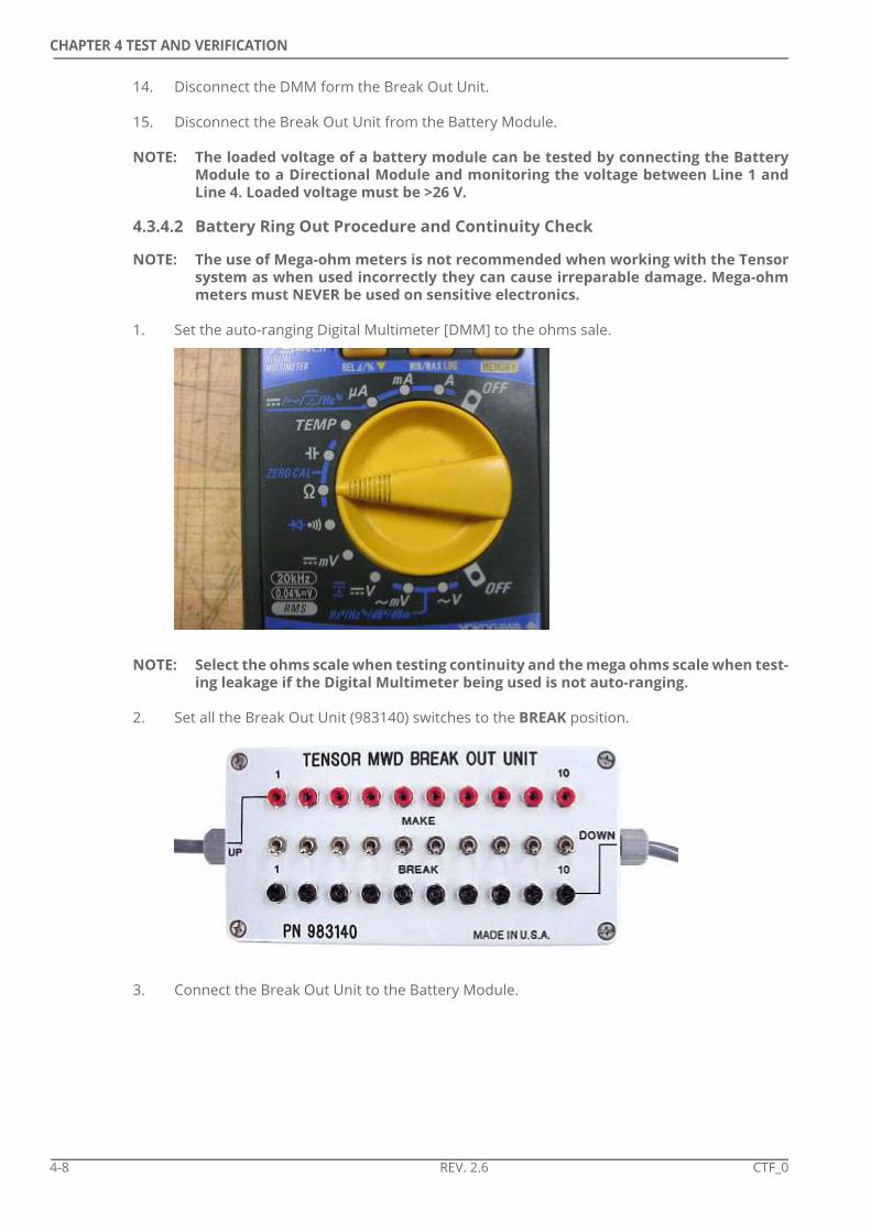
1. Set the auto-ranging Digital Multimeter [DMM] to the ohms sale.
NOTE: Select the ohms scale when testing continuity and the mega ohms scale when test-ing leakage if the Digital Multimeter being used is not auto-ranging.
2. Set all the Break Out Unit (983140) switches to the BREAK position.
3. Connect the Break Out Unit to the Battery Module.
4-8 REV. 2.6 CTF_0

CHAPTER 4 TEST AND VERIFICATION
a) Connect the 6 pin, 4 socket test connector to the downhole Battery Moduleconnector.
b) Connect the 4 pin, 6 socket test connector to the uphole Battery Module connector.
4. Refer to Table 4-2.
5. Working from left to right across the Break Out Unit: plug the red lead into the Break-outUnit red socket number 1 and plug the black lead into the Break-out Unit black socketnumber 1.
6. Verify that the Multimeter reading conforms to the readings in Table 4-2.
7. Test all the socket combinations listed in Table 4-2.Table 4-2 Battery Continuity Check Procedure
NOTE: Polarity must be observed to make correct measurements. Connect as follows:Red or (+) lead to the Up Hole connector on the Break Out Unit. Black or (-) lead tothe Down Hole connector on the Break Out Unit. Pay close attention to the limitvalues in each cell.
NOTE: Do NOT uphole line 2 to downhole line 3. This may result in a catastrophic short circuit.Do not connect line 1 to uphole line 2, or line 1 to downhole line 3 as this can seriously damage the meter.
BLACK (down hole)Line 1 2 3 4 5 6 7 8 9 10
RED
(up
hole
)
1 <1.0 O.L.
2 O.L.
3 O.L. <1.0 O.L.
4 O.L. O.L. O.L. <1.0
5 O.L. O.L. O.L. O.L. <1.0
6 O.L. O.L. O.L. O.L. O.L. <1.0
7 O.L. O.L. O.L. O.L. O.L. O.L. <1.0
8 O.L. O.L. O.L. O.L. O.L. O.L. O.L. <1.0
9 O.L. O.L. O.L. O.L. O.L. O.L. O.L. O.L. <1.0
10 O.L. O.L. O.L. O.L. O.L. O.L. O.L. O.L. O.L. <1.0
Body/ Case
O.L. O.L. O.L. O.L. O.L. O.L. O.L. O.L. O.L. O.L.
NOTE: Do NOT test combinations indicated by black cells as a short circuit may result.
CTF_0 REV. 2.6 4-9

CHAPTER 4 TEST AND VERIFICATION
NOTE: <1.0 measured on the ohms scale
NOTE: O.L = Open Load (open circuit) measured on mega-ohms scale
8. Disconnect the DMM from the Break Out Unit.
9. Disconnect the Break Out Unit from the Battery Module.
10. Check, and replace if necessary, the O-ring AS-220 (422900/ 411931) on each Thread Pro-tector Module End (981845)
11. Install the Thread Protectors on both ends of the Battery Module.
4.3.5 Testing and Storage of Multiple Battery Assemblies
2 or 3 Battery Modules are used when running Centerfire. When preparing for operationsthese batteries can be connected and stored inside to prevent cold temperature reducingtheir operating voltage. The following points relating to multiple battery assemblies shouldbe considered:
• Each Battery Module should be tested individually and not after connection to another Module.Checking the voltage of a combination of 2 or more Battery Modules will not indicate if anyof the Battery Modules has a problem.
• Having Battery Modules connected will not lead to any depletion of the Modules. Depletion will only begin once connected to a Directional Module or Centerfire tool.
4-10 REV. 2.6 CTF_0

CHAPTER 4 TEST AND VERIFICATION
4.4 Directional Module
The Centerfire system requires either a 2-Bay or 3-Bay Directional Module loaded withversion 2+ firmware to be used to allow transmission of realtime data. The DirectionalModule should be tested before connection to the string.
1. Set the auto-ranging Digital Multimeter [DMM] to the Ohms scale.
NOTE: Select the Ohms scale when testing continuity and the Mega Ohms scale whentesting leakage if the Digital Multimeter being used is not auto-ranging.
2. Set all the Break Out Unit (983140) switches to the MAKE position.
3. Connect the Break Out Unit to the Directional Module.a) Connect the 6 pin, 4 socket test connector to the downhole Directional Module
connector.
b) Connect the 4 pin, 6 socket test connector to the uphole Directional Moduleconnector.
4. Insert the red probe from DMM into the number 1 Red socket in the Break Out Unit. Pressthe black probe firmly to the pressure housing and hold in place.
CTF_0 REV. 2.6 4-11

CHAPTER 4 TEST AND VERIFICATION
5. Confirm the DMM shows an Open Load signifying there is no short circuit from line 1 to thePressure Housing.
6. Repeat steps 4. and 5. for the remaining nine lines.
7. Remove the red probe from the Break Out Unit and set all the switches to the BREAK posi-tion.
4-12 REV. 2.6 CTF_0

CHAPTER 4 TEST AND VERIFICATION
8. Insert the red probe into the Line 1 red socket and the black probe into the Line 1 blacksocket. Allow the reading to stabilise and confirm the reading is <1.0. Ohm.
9. Move the red probe to the Line 2 red socket and the black probe to Line 2 black socket.Allow the reading to stabilise and confirm the reading is <1.0. Ohm.
10. Repeat for the remaining lines.Table 4-3 DM Ring Out
11. Disconnect the DM from the Break Out Unit.
12. Disconnect the Break Out Unit from the Directional Module.
13. Check, and replace if necessary, the O-ring AS-220 (422900/ 411931) on each Thread Pro-tector Module End (981845)
14. Install the Thread Protectors on both ends of the Directional Module.
Line 1-1 2-2 3-3 4-4 5-5 6-6 7-7 8-8 9-9 10-10
Limit (Ohms) <1.0 <1.0 <1.0 <1.0 <1.0 <1.0 <1.0 <1.0 <1.0 <1.0
Line to Barrel (Mega Ohms)
>1 >1 >1 >1 >1 >1 >1 >1 >1 >1
CTF_0 REV. 2.6 4-13

CHAPTER 4 TEST AND VERIFICATION
4.5 Centerfire Pulser
The Centerfire Pulser must be physically and electrically tested to ensure it will operatedownhole.
4.5.1 Pulser Physical Inspection
1. Remove the Thread Protector and check the 6 pin connector for any damaged or bentpins.
2. Check, and replace where necessary, the O-rings, Back up Rings, Conductor Springs andWiper Seals on the Wet Connect.
Figure 4-3 Male Wet Connect Seals
NOTE: Alternative O-rings are available for use in very low temperatures (-26ºC/ -15ºF).Replace 411947 with 422519.
3. Check, and replace if necessary, the 221 O-ring (422992/ 422304) on the Pulser Helix End
4. Inspect the Helix End and confirm the shaft returns after being pushed.
Item Description Quantity Part1 O-ring 4 411947
2 Back Up Ring 4 971915
3 Conductor Spring 6 422400
4 Wiper Seal 6 971916
11 2 3 12 2123 33 34 4 4 4 4 4 3
4-14 REV. 2.6 CTF_0

CHAPTER 4 TEST AND VERIFICATION
4.5.2 Pulser Electrical Test
The Wet Connect should be tested to ensure the wiring from the Battery through theDirectional Module to the Pulser is good. Only one battery is required for this test.
NOTE: The Directional Module can be placed below the battery, directly above the Pulser,ONLY IF the Jumper module is already connected to the battery.
1. Connect the 4-pin connector of a Jumper Cable (983150) to the uphole end of the Pulserand the 6-pin connector to the downhole end of a battery.
2. Connect the 4-pin connector of a Jumper Cable (983150) to the uphole end of the batteryand the 6-pin connector to the downhole end of the Directional Module.
3. Set the Digital Multi-meter to the Voltage setting.
Figure 4-4 Male Wet Connect Wiring
A - Downhole B - UpholeItem Description
1 Ground
2 qBUS
3 Sense
4 Float
5 Battery
3 421 5
BA
CTF_0 REV. 2.6 4-15

CHAPTER 4 TEST AND VERIFICATION
4. Probe the Wet Connect bands: note that the arrow indicates DOWNHOLE.a) Hold the Black DMM probe on the Ground band and the red probe on the Battery
band. The DMM will display ~0 V. If the display is anything other than 0 V, do not usethe Pulser.
b) Use a short piece of wire to create a short circuit by connecting the Sense andGround bands.
c) Hold the Black DMM probe on the Ground band and the red probe on the Batteryband. The DMM will display ~24 V.
d) Remove the short circuit connector wire. Hold the Black DMM probe on the Groundband and the red probe on the Battery band. The DMM will again display ~0 V.
e) Hold the Black DMM probe on the Ground band and the red probe on the Floatband. The DMM will display ~0 V. If the display is anything other than 0 V, do not usethe Pulser.
f) Hold the Black DMM probe on the Ground band and the red probe on the Senseband. The DMM will display >25 V. If the voltage is less than 25 V, replace the BatteryOR check to see if it is a new or already-used one. If already used, how many hoursremaining for operation?
g) Hold the Black DMM probe on the Ground band and the red probe on the qBusband. The DMM will display >2 V. If the voltage is not >2 V, change the battery and/or the DM to confirm that the problem is NOT with the Pulser.
NOTE: The qBus is nominally low with signal transitions to +5 V. When measuring thiswith a multimeter (DC Voltmeter) the measurement is that where the voltmeterhas integrated the positive going signal transitions. Therefore voltage swings to +2V are normal. Depending on the multimeter used however this integrated valuemay be lower than +2 V. To ensure the qBUS has a good quality 0-5 VDC signal anoscilloscope can be used.
4-16 REV. 2.6 CTF_0

CHAPTER 4 TEST AND VERIFICATION
4.5.3 Tap Test
The Pulser can be stimulated to simulate a Flow On event to ensure it starts pulsing.
1. Connect the Pulser, Directional Module and Battery Module as described in 4.5.2.
2. Attach the Helix to the Pulser.
3. Remove a servo poppet screen for better visibility.
4. Firmly tap the helix end, using a metal tool, for 1 minute.
NOTE: This test is best done with the Pulser out of the Centerfire collar. If a test isrequired with the Pulser connected to the Centerfire tool, REMOVE all O-rings,back-up rings and wipers. The Pulser may not come out of the collar if this is notdone.
NOTE: The Pulser can be in the Centerfire collar in which case the tool can be tapped atthe upper end of the Pulser, at the Pulser Driver (not at the Compensation Hous-ing).
5. After the Transmit Delay Time (set in the tool configuration) has elapsed, the tool will startpulsing. Observe the servo poppet opening and closing.
CTF_0 REV. 2.6 4-17

CHAPTER 4 TEST AND VERIFICATION
4.5.4 Poppet Tip Installation
The strength of the MWD mud signal pulse is largely controlled by the flow rate, MuleshoeOrifice internal diameter and the Pulser Poppet external diameter. Selection of Orifice andPoppet is determined by the expected flow rate as described in Table 4-4.
NOTE: Table 4-4 is only applicable when the mud weight is comparable to water. Use theTensor Operations Calculator to determine recommended Poppet-Orifice combi-nations to use when the mud weight is greater than that of water. The Calculatorcan be downloaded from the Technical Support Portal.
NOTE: 1.55” & 1.60” Orifices are for use with the 6.5”/ 8.0” Muleshoe.Table 4-4 Main Poppet Selection
The Muleshoe Orifice is usually installed in the workshop. For more information refer toCenterfire Maintenance Manual (981021-100-06).
Main Orifice I.D.
Part Number
Poppet End O.D.
Part Number
Flow Area (in2)
Flow Range (GPM / l/s)
1.28 981068 1.122 981140 0.297 215-240 / 13.56-15.14
1.28 981068 1.086 981213 0.360 260-295 / 16.40-18.61
1.28 981068 1.040 981214 0.437 320-375 / 20.19-23.66
1.35 981067 1.122 981140 0.443 320-375 / 20.19-23.66
1.35 981067 1.086 981213 0.505 370-430 / 23.34-27.13
1.35 981067 1.040 981214 0.582 450-500 / 28.39-31.55
1.40 981066 1.122 981140 0.550 420-480 / 26.50-30.28
1.40 981066 1.086 981213 0.612 475-535 / 29.97-33.75
1.40 981066 1.040 981214 0.690 530-620 / 33.44-39.12
1.50 981051 1.122 981140 0.778 610-680 / 38.48-42.90
1.50 981051 1.086 981213 0.840 670-750 / 42.27-47.32
1.50 981051 1.040 981214 0.918 770-830 / 48.58-52.36
1.55 981059 1.122 981140 0.898 725-800 / 45.74-50.47
1.55 981059 1.086 981213 0.961 800-875 / 50.47-55.20
1.55 981059 1.040 981214 1.037 900-975 / 56.78-61.51
1.60 981060 1.122 981140 1.022 850-925 / 53.63-58.36
1.60 981060 1.086 981213 1.084 925-1025 / 58.36-64.67
1.60 981060 1.040 981214 1.161 980-1200 / 61.83-75.71
4-18 REV. 2.6 CTF_0

CHAPTER 4 TEST AND VERIFICATION
Operators may have to change the Poppet Tip at the rigsite to maximise pulse size.
1. Select the correct Poppet Tip based on Table 4-4.
2. Apply Loctite 246 to the threads of the Poppet Tip.
3. Screw the Poppet Tip into the Pulser Lower End.
4. Secure the Pulser Assembly from rotating by way of an adjustable wrench across the flatson the Signal Shaft.
5. Torque the Poppet Tip to 45 lbf.ft (61 Nm) using a 3/8” Driver.
CTF_0 REV. 2.6 4-19

CHAPTER 4 TEST AND VERIFICATION
4.6 Centerfire Collar
The Centerfire needs to be physically inspected and function tested before every run.
4.6.1 Physical Inspection
1. Use a steam cleaner or high pressure washer to remove all drilling fluid from the tool.Pay particular attention to all the bolts holding the Hatch Covers in place, the Wet Con-nect, the Gamma Centraliser and the Muleshoe.
2. Check all Hatch Covers for broken bolts. Check that the bolts are still torqued.
3. Check all Anchor Bolts are secure and, where applicable, Seal Covers and Retaining Ringsare in place.
4. Check the Antenna Covers for cracks, gouges or wash. Check for broken bolts.
NOTE: New collars may have extrusions of black rubber from the Antennae Covers. Thisis normal and should NOT be removed.
NOTE: Be aware that the tool may still contain drilling fluids that can be caus-tic or highly irritating.
4-20 REV. 2.6 CTF_0

CHAPTER 4 TEST AND VERIFICATION
5. Check the Wear Bands and antennas for cracking or chipping. Compare the Wear Banddiameters against the nominal values below: us an Outside Diameter [OD] Calliper.• 4.75” - 5.00” (127 mm) Antennae, 5.25” (133.4 mm) Wear Band• 6.91” - 6.91” (175.5 mm) Antennae, 7.16” (181.8 mm) Wear Band• 8.25” - 8.25” (209.6 mm) Antennae, 8.50” (215.9 mm) Wear Band
6. Connections: these should be given a brief inspection; a detailed inspection should be car-ried out by a third-party inspector once the tool has returned to the workshop.
CTF_0 REV. 2.6 4-21

CHAPTER 4 TEST AND VERIFICATION
4.7 Software Installation
To ensure the Centerfire system operates correctly the most up-to-date software must beused when communicating with the tool or running the system. The latest version of qMWDsoftware can be downloaded from the Tensor Technical Support portal atwww.tesnordt.com.
NOTE: Access to this website requires registration and a password is required to openfiles downloaded from the site. Contact the Regional Office for information on reg-istration and passwords.
1. Download the latest version of qMWD software from the Technical Support website.
2. Open the zip archive and click on the qMWD_PWR_LV.exe installer file.
4-22 REV. 2.6 CTF_0

CHAPTER 4 TEST AND VERIFICATION
3. Enter the password to unzip the files.
4. Run the qMWD_PWR-LV.exe installer program.
5. Accept the standard installation preferences.
6. Restart the computer when prompted.
4.7.1 USB Driver Installation
When the PC is connected to the Safe Area Interface [SAI] drivers will be required forcommunications. Instructions on how to load the Drivers for Win2k or WinXP are found inseparate documents in the USB folder in the qMWD Software zip archive.
NOTE: Failure to follow the instructions in these documents will result in the PC not beingable to communicate with the SAI and tools.
CTF_0 REV. 2.6 4-23

CHAPTER 4 TEST AND VERIFICATION
4.8 Tool Communications
Communications with Centerfire and the MWD tool string can be achieved using differentmethods.
4.8.1 PC to SAI Communications
The SAI allows serial (qNIC) or USB connection to the PC from the “Safe Area PC” connections.The functionality of both connections are identical.
NOTE: Only one cable should connect the PC to the SAI. Never use both qNIC and USB atthe same time.
4.8.2 SAI to Tool
Communications from the SAI to the Centerfire or MWD toolstring can be achieved usingdifferent SAI ports depending on the operation being performed.
Table 4-5 Communication Options
4.8.3 Communication Considerations
The following points apply to all communications between the PC and the Centerfire or MWDString.
• Ensure all power switches on the SAI are in the OFF position before making or breaking any communication connections.
• Ensure all qMWD applications are closed before making or breaking any communication connections.
• Pay attention to all keys and locators on cables. Connections never need to be forced to mate. If force is required the reason must be identified and remedied. Excessive force may result in irreparable damage to cables, tools and/ or SAI.
SAI Port Cable Tool Connection Purpose
PWR POD
PWR Interface POD Cable (384339) (SAI to POD Extension Cable (384335))
Centerfire Memory Dump Port
Centerfire Communica-tions, Centerfire and con-nected MWD Toolstring Communications.
Tool Pro-gram-ming
Programming Cable (384025)
Programming Top (983130) on top of MWD String
Centerfire and connected MWD Toolstring Commu-nications
qBUS qBUS Cable (384008) Programming Top (983130) on top of MWD String
Firmware upgrade
4-24 REV. 2.6 CTF_0

CHAPTER 4 TEST AND VERIFICATION
4.9 Firmware Upgrades
New software can require upgrades to the firmware that controls the operation of variouscomponents of the system. Every installation of qMWD includes a document calledVersion.txt which lists the most up to date firmware versions.
Firmware versions can be checked and updated using the qTalk and W32FirmwareLoaderutilities. Refer to the Centerfire Maintenance Manual (981201-100-06) for more informationon this procedure.
NOTE: Version 2 or 3 firmware must be loaded on to the Directional Modules to allowthem to operate with the Centerfire system.
CTF_0 REV. 2.6 4-25

CHAPTER 4 TEST AND VERIFICATION
4.10 Centerfire Communications Test
The tool must be connected to the PC by way of the SAI to ensure communications are active.
The Gamma Module in the 4.75” and 6.91” tools should have been connected in theworkshop. Refer to the Centerfire Maintenance Manual (981201-100-06) for details on howto connect the Gamma Module if it has not ben assembled.
1. Use a 5-16” hex wrench to loosen the 2 x Bolts and remove the Data Dump Cover.
2. Connect the PWR Interface POD Cable (384339) to the Centerfire Tool.
NOTE: Connectors on the cable have a key pin and socket of unique size which ensure thepins mate correctly. Damage will result if the connector is forced onto the toolwithout aligning the key pin and mating socket.
4-26 REV. 2.6 CTF_0

CHAPTER 4 TEST AND VERIFICATION
3. Connect the POD Cable to the PWR POD Port on the Safe Area Interface [SAI] (RS-384356).Use of the SAI to POD Extension Cable (384335) may be necessary.
4. Connect the PC to the SAI using the USB Cable (460003) or an RS232 cable.
5. Turn the following to ON: SAI Power, Receiver Comm.
CTF_0 REV. 2.6 4-27

CHAPTER 4 TEST AND VERIFICATION
6. From the Programs menu on the PC select <qMWD> <Diagnostics> <qW32Server>. Alter-natively, from the desktop on the QMWD laptop, open the QMWD folder, and then openthe Diagnostic folder.
7. When using a qNIC (serial cable), ensure the qW32 Server window displays: xxxxxxx qNIC server found on yyyy
xxxxxxx Server Polling yyyy
Where xxxxxx = a time stamp and yyyy = PC port being used.
The qWD32Server window will flash up and down from the Taskbar if there are anycommunication problems.
4-28 REV. 2.6 CTF_0

CHAPTER 4 TEST AND VERIFICATION
8. When using a USB cable the message will be similar to:-
9. Start the Node Status application. Check that Nodes 05 (MPRx) and 23 (PWR) are displayedand that no Faults or Warning are reported. Refer to Section 4.12 if a memory fault is dis-played on Node 23. Check cables if Nodes are not displayed.
10. Exit the Node Status and start the qTalk application.
11. Ensure the Destination Address is 23 and type: rccd?
CTF_0 REV. 2.6 4-29

CHAPTER 4 TEST AND VERIFICATION
12. Click on ‘Send Message’
13. Confirm that the Response window in qTalk shows the following data sets and that thedata is non-zero:• CCP1 - Compensated 400 kHz 19” Phase Difference in degrees• CCP2 - Compensated 2 MHz 19” Phase Difference in degrees• CCP3 - Compensated 400 kHz 41” Phase Difference in degrees• CCP4 - Compensated 2 MHz 41” Phase Difference in degrees• CCA1 - Compensated 400 kHz 19” Attenuation in decibels• CCA2 - Compensated 2 MHz 19” Attenuation in decibels• CCA3 - Compensated 400 kHz 41” Attenuation in decibels• CCA4 - Compensated 2 MHz 41” Attenuation in decibels
NOTE: The CCP1 - CCA4 data sets represent raw data that has not yet had the resistivitytransform applied.
4-30 REV. 2.6 CTF_0

CHAPTER 4 TEST AND VERIFICATION
14. Scroll to the right of the data set and confirm the gamma reading is non-zero.Check that ReSR is $0000. Refer to Section 5.2.3 for more details on ReSR.
15. Ensure the Destination Address is 23 and send the message: hkd?
16. Confirm that the Response window in qTalk shows the following data sets and that thedata is as expected:• RBLo- Low voltage as measured on the Centerfire collar. When powered by the SAI
this is usually ~ 27-28 V.• RIMx - Maximum current measured in the previous acquisition sequence. Usually
260-360 but can be higher if the antennas are in contact with metal. Consult Tensor DT if higher than 450.
• RIAv- Average current. Non-zero• RIMn- Minimum current. Non-zero• RPAv - Positive voltage ~ 5.0• RPAv - Negative voltage ~ -5.0• RDiV - Digital voltage ~ 5.0• RTMp- Temperature.
CTF_0 REV. 2.6 4-31

CHAPTER 4 TEST AND VERIFICATION
4.11 String Test
A full string test is the most complete test of the system. The Centerfire Tool is connected tothe MWD string with which it will be run to ensure communications are as expectedthroughout the string. It is not possible to generate real time data that could be displayed inqMWDPC but all data can be viewed in qTalk.
4.11.1 Toolstring Assembly Overview
The outline of the correct procedure is:
1. Attach Interconnects to the bottom of all tool modules except the Pulser.
2. Connect the 3 x Battery modules. Refer to Section 4.3 for information on batteries to beused with the Centerfire system.
3. Insert the Pulser into the Centerfire - remove all seals, back-ups and wipers from the MaleWet Connect.
4. Connect the Directional Module to the Pulser using a jumper cable.
5. Connect the 2 or 3 x Batteries to the Directional Module.
NOTE: It is critical that the MWD modules are connected in the correct order. Failure to follow the correct order may result in irreparable damage to one or more modules.
4-32 REV. 2.6 CTF_0

CHAPTER 4 TEST AND VERIFICATION
4.11.2 Interconnect Assembly
Interconnects should be connected to ALL MWD tool modules before the connection of thestring. Refer to Interconnect Maintenance Manual (981021-100-02) for more information onInterconnect maintenance. Interconnects are always installed at the lower (downhole) end ofthe tool modules.
NOTE: Interconnects should ideally be connected to tool modules in the workshop andshould not be removed at the rigsite.
1. Identify the top and bottom connections of each Interconnect and Tool Modules. Upholeconnections have 6 pins and 4 sockets:
Downhole connections have 4 pins and 6 sockets:
Interconnects should have the Spring on the downhole end. Refer to the InterconnectMaintenance Manual for more information.
2. Check the thread on the bottom of the tool module to ensure it is clean, free from debrisand contains no sharp edges or burrs which could damage seals. The bottom of the toolmodule has the connection with 4 pins and 6 sockets.
3. Select the Interconnect to be run with the tool module. Note the serial numbers of both.
NOTE: Where possible Interconnects should be paired with a tool module and always runwith it. This will aid troubleshooting should problems arise.
CTF_0 REV. 2.6 4-33

CHAPTER 4 TEST AND VERIFICATION
4. Check the O-ring 027 (422342/ 422301/ 981507) seals and Split Shear Ring (981503) on theInterconnect. Replace any that are not in perfect condition.
5. Align the key of the 4-pin 6-socket connector to the downward position. Make a mark onthe housing, opposite the key.
6. On the body of one interconnect find the key of the 4-pin 6-socket connector and make amark on the shaft where the compression spring is located that is aligned with the key.
4-34 REV. 2.6 CTF_0
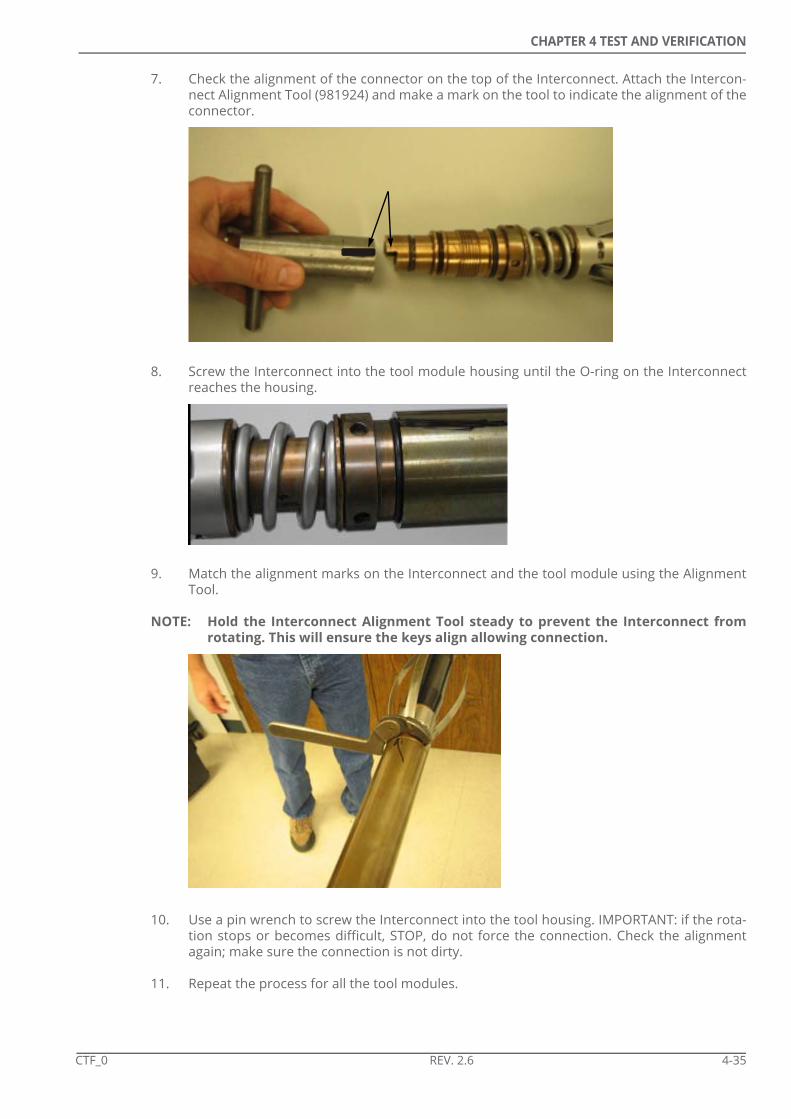
CHAPTER 4 TEST AND VERIFICATION
7. Check the alignment of the connector on the top of the Interconnect. Attach the Intercon-nect Alignment Tool (981924) and make a mark on the tool to indicate the alignment of theconnector.
8. Screw the Interconnect into the tool module housing until the O-ring on the Interconnectreaches the housing.
9. Match the alignment marks on the Interconnect and the tool module using the AlignmentTool.
NOTE: Hold the Interconnect Alignment Tool steady to prevent the Interconnect fromrotating. This will ensure the keys align allowing connection.
10. Use a pin wrench to screw the Interconnect into the tool housing. IMPORTANT: if the rota-tion stops or becomes difficult, STOP, do not force the connection. Check the alignmentagain; make sure the connection is not dirty.
11. Repeat the process for all the tool modules.
CTF_0 REV. 2.6 4-35

CHAPTER 4 TEST AND VERIFICATION
4.11.3 Toolstring Connection
NOTE: All the Battery Modules should be connected before any other tool modules areconnected.
Three batteries are recommended to power the Centerfire system. For more information onbatteries refer to Section 4.3 and the Battery Maintenance Manual (981021-100-01).
1. Select the Battery to be positioned at the top of the string (Battery 3).
2. Check the O-ring 027 (422342/ 422301/ 981507) seals and Split Shear Ring (981503) on theInterconnect. Replace any that are not in perfect condition.
3. Check the thread on the top of the Battery to be positioned next in the string (Battery 1) toensure it is clean, free from debris and contains no sharp edges or burrs which could dam-age seals.
4. Check the alignment of the connector on the top of the tool module. Make a mark on thehousing to indicate the alignment.
5. Check the alignment of the connector on the bottom of the Interconnect. Make a mark onthe non-rotating central shaft of the Interconnect (under the spring) to indicate the align-ment of the connector.
4-36 REV. 2.6 CTF_0

CHAPTER 4 TEST AND VERIFICATION
6. Screw the two modules together.
7. Stop when the O-ring is reached.
8. Back off the connection slightly and align the marks on the Module and the Interconnect.
9. Secure the assembly with Friction Wrenches to stop it from rotating.
10. Tighten the connection using the Pin Wrench on the Interconnect.
11. Repeat to attach the lowest Battery (Battery 2) to the bottom of the string.
12. Check the Contact Springs (422400) on the Male Wet Connect at the Bottom of the Pulser.
13. Remove all seals, back-ups and wipers before inserting the Pulser into the Centerfire col-lar. The Pulser may stick in the collar at the end of the tests if this is not done.
CTF_0 REV. 2.6 4-37
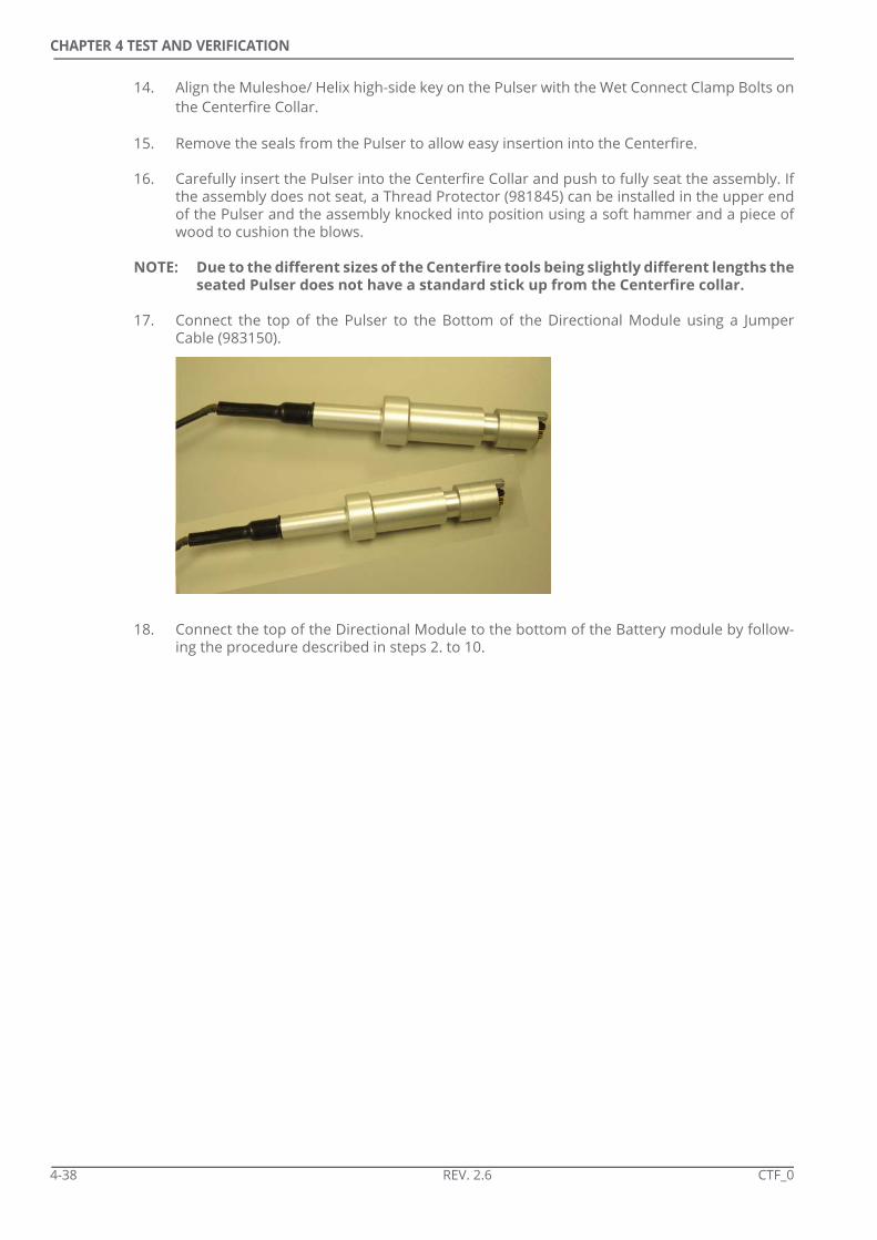
CHAPTER 4 TEST AND VERIFICATION
14. Align the Muleshoe/ Helix high-side key on the Pulser with the Wet Connect Clamp Bolts onthe Centerfire Collar.
15. Remove the seals from the Pulser to allow easy insertion into the Centerfire.
16. Carefully insert the Pulser into the Centerfire Collar and push to fully seat the assembly. Ifthe assembly does not seat, a Thread Protector (981845) can be installed in the upper endof the Pulser and the assembly knocked into position using a soft hammer and a piece ofwood to cushion the blows.
NOTE: Due to the different sizes of the Centerfire tools being slightly different lengths theseated Pulser does not have a standard stick up from the Centerfire collar.
17. Connect the top of the Pulser to the Bottom of the Directional Module using a JumperCable (983150).
18. Connect the top of the Directional Module to the bottom of the Battery module by follow-ing the procedure described in steps 2. to 10.
4-38 REV. 2.6 CTF_0

CHAPTER 4 TEST AND VERIFICATION
4.11.4 Top Communications
1. Follow the steps in Section 4.11.3 to connect the string.
2. Connect the Programming Top (983130) to the top of the top Battery.
3. Connect the Programming Top to the Programming Cable (384025).
4. Connect the Programming Cable to the Tool Programming socket on the SAI.
5. Connect the PC to the SAI using USB Cable (460003) or an RS232 cable.
CTF_0 REV. 2.6 4-39

CHAPTER 4 TEST AND VERIFICATION
6. Turn the SAI Power switch to the ON position.
7. Turn the Receiver Comm switch to the ON position.
8. Keep the Tool switch in the OFF position. The batteries in the MWD string will power thesystem.
9. From the Programs menu on the PC select <qMWD> <Diagnostics> <qW32Server>. Whenusing a qNIC (serial cable), ensure the qW32 Server window displays:
xxxxxxx qNIC server found on yyyy
xxxxxxx Server Polling yyyy
Where xxxxxx = a time stamp and yyyy = PC port being used.
The qW32Server window will flash up and down from the Taskbar if there are anycommunication problems.
10. When using a USB cable the message will be similar to:-
4-40 REV. 2.6 CTF_0

CHAPTER 4 TEST AND VERIFICATION
11. Start the Node Status application in qW32 Server and check the correct nodes are dis-played:-• 2- Bay DM - MPRx (05), MPTx (20), CTF (23)• 3- Bay DM - MPRx (05), MPTx (20), DGS (21), CTF (23)No Faults or Warning should be reported. Refer to Section 4.12 if a memory fault isdisplayed. Check cables and seating of the Male Wet Connect if Nodes are not displayed.
NOTE: Close qW32 Server and switch off all power before investigating any bad connec-tions.
12. Start the qTalk application.
13. Ensure the Destination Address is xx and type: rccd?
14. Confirm that the Response window in qTalk shows the following data sets update for bothNode 20 and Node 23:• CCP1 - Compensated 400 kHz 19” Phase Difference in degrees• CCP2 - Compensated 2 MHz 19” Phase Difference in degrees• CCP3 - Compensated 400 kHz 41” Phase Difference in degrees• CCP4 - Compensated 2 MHz 41” Phase Difference in degrees• CCA1 - Compensated 400 kHz 19” Amplitude ratio• CCA2 - Compensated 2 MHz 19” Amplitude ratio• CCA3 - Compensated 400 kHz 41” Amplitude ratio• CCA4 - Compensated 2 MHz 41” Amplitude ratio• Gama - Gamma Sensor
15. Close all software applications.
16. Turn the Receiver Comm switch to the OFF position.
17. Turn the SAI Power switch to the OFF position.
18. Disconnect the Programming Top from the top Battery.
CTF_0 REV. 2.6 4-41

CHAPTER 4 TEST AND VERIFICATION
4.11.5 Dump Port Communications
1. Insert the Battery Jumper Plug (981524) into the top of the Interconnect on the top battery.
2. Attach the Spear Point (981925) to the top of the top Battery.
3. Remove the Centerfire Data Dump Port Cover to gain access to the connector pins.
4. Using a multimeter check the voltage between the pins below and the collar body.
NOTE: The qBus is nominally low with signal transitions to +5 V. When measuring this
Pin DescriptionRequired Voltage Between Pin and Collar
2 BatBus >25V3 qBUS ~2V
7 Data ~5V
7
6
1
3
2
5 4
4-42 REV. 2.6 CTF_0

CHAPTER 4 TEST AND VERIFICATION
with a multimeter (DC Voltmeter) the measurement is that where the voltmeterhas integrated the positive going signal transitions. Therefore voltage swings to +2V are normal. Depending on the multimeter used however this integrated valuemay be lower than +2 V. To ensure the qBUS has a good quality 0-5 VDC signal anoscilloscope can be used.
5. Connect the PWR Interface POD Cable (384339) to the Centerfire Tool.
6. Connect the POD Cable to the PWR POD Port on the Safe Area Interface [SAI] (RS-384356).Use of the SAI to POD Extension Cable (384335) may be necessary.
7. Connect the PC to the SAI using the USB Cable (460003) or an RS232 cable.
8. Turn the SAI Power switch to the ON position.
9. Turn the Receiver Comm switch to the ON position.
CTF_0 REV. 2.6 4-43

CHAPTER 4 TEST AND VERIFICATION
10. Keep the Tool Power switch in the OFF position.
11. From the Programs menu on the PC select <qMWD> <Diagnostics> <qW32Server>.Ensure the qW32 Server window displays:
xxxxxxx qNIC server found on xxxxx
xxxxxxx Server Polling xxxxx
The qWD32Server window will flash up and down from the Taskbar if there are anycommunication problems.
12. Start the Node Status application in qW32 Server and check the correct nodes are dis-played:-• 2- Bay DM - MPRx (05), MPTx (20), CTF (23)• 3- Bay DM - MPRx (05), MPTx (20), DGS (21), CTF (23)No Faults or Warning should be reported. Refer to Section 4.12 if a memory fault isdisplayed. Check cables if Nodes are not displayed.
NOTE: Close qW32 Server and switch off all power before investigating any bad connec-tions.
13. Start the qTalk application.
14. Ensure the Destination Address is xx and type: rccd?
15. Confirm that the Response window in qTalk shows the following data sets update for bothNode 20 and Node 23:• CCP1 - Compensated 400 kHz 19” Phase Difference in degrees• CCP2 - Compensated 2 MHz 19” Phase Difference in degrees• CCP3 - Compensated 400 kHz 41” Phase Difference in degrees• CCP4 - Compensated 2 MHz 41” Phase Difference in degrees• CCA1 - Compensated 400 kHz 19” Amplitude ratio• CCA2 - Compensated 2 MHz 19” Amplitude ratio• CCA3 - Compensated 400 kHz 41” Amplitude ratio• CCA4 - Compensated 2 MHz 41” Amplitude ratio• Gama - Gamma Sensor
16. Close all software applications.
17. Turn the Receiver Comm switch to the OFF position.
4-44 REV. 2.6 CTF_0

CHAPTER 4 TEST AND VERIFICATION
18. Turn the SAI Power switch to the OFF position.
19. Close all software applications.
4.11.6 Tap Test
The Pulser can be stimulated to simulate a Flow On event to ensure it starts pulsing.
1. Firmly tap the top of the Pulser where it leaves the Centerfire collar using a metal tool.
2. After the Transmit Delay Time (set in the tool configuration) has elapsed, the tool will startpulsing.
4.11.7 Disassembly
The procedure is the reverse of the assembly procedure.
1. Disconnect the Jumper Cable between the Pulser and the Directional Module.
2. Disconnect the Directional Module from the bottom battery.
3. Disconnect the bottom battery from the second battery and the second from the third.
NOTE: It is very important that the tool is disconnected in the correct order. Failure to follow the correct procedure may result in irreparable dam-age to one or more tool modules.
CTF_0 REV. 2.6 4-45

CHAPTER 4 TEST AND VERIFICATION
4.12 Memory Test
The Centerfire tool logs to its memory when it is powered up and the recorder file is open.Files will remain open until the operator closes them regardless of whether the tool ispowered up or not. The Centerfire memory stores raw data for calculation of resistivityvalues and also gamma data. When the memory file is full the recorder will stop recordingdata.
When a Directional Module is connected to the Centerfire it will record compensatedresistivity values and gamma values in the PCD file stored on the MPTx board. It also storesTemperature data.
The Memory I/O utility is used to access the data that is recorded to the PWR memory in theCenterfire tool and the DGS and MPTx memory in the Directional Module. Table 4-6 describesthe recorded data files that relate to the Centerfire system.
Table 4-6 Memory Files
NOTE: Before testing the memory the operator must be sure that all required data hasbeen copied from the tool as the test involves erasing the memory.
All locations of memory in the tool are checked to ensure they record data as expected.
1. Make sure the PC time and date are correct.
2. Start up qMWD Server on the PC. If it is not running, Memory I/O will not open.
3. Connect to the tool as described in Section 4.11, “String Test”.
NOTE: To test the Centerfire Memory without the MWD string, connect to the tool asdescribed in Section 4.8. Only data sets associated with Node 23 will be available(see Table 4-6).
Location Memory Node Data Set Description
Centerfire PWR 23 PRD Raw R and X measurements used to calculate resistivityGammaDiagnostic currents, voltages and temperatureReSR word (Firmware V02.01J or later)
2-Bay DM MPTx 20 Batt Battery Voltage
MPTx 20 Circ Circulating time
MPTx 20 PCD Compensated Resistivity (4 x PD, 4 x AT). Gamma.
MPTx 20 TmpR Temperature
3-Bay DM MPTx 20 Batt Battery Voltage
MPTx 20 Circ Circulating time
MPTx 20 PCD Compensated Resistivity (4 x PD, 4 x AT). Gamma.
DGS 21 TmpR Temperature
4-46 REV. 2.6 CTF_0
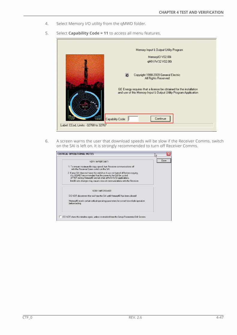
CHAPTER 4 TEST AND VERIFICATION
4. Select Memory I/O utility from the qMWD folder.
5. Select Capability Code = 11 to access all menu features.
6. A screen warns the user that download speeds will be slow if the Receiver Comms. switchon the SAI is left on. It is strongly recommended to turn off Receiver Comms.
CTF_0 REV. 2.6 4-47

CHAPTER 4 TEST AND VERIFICATION
7. Check that all expected Nodes are displayed on the list on the left of the screen.
8. Select the Set System Time option from the Commands menu.
4-48 REV. 2.6 CTF_0

CHAPTER 4 TEST AND VERIFICATION
9. Select each of the nodes by clicking on it on the left of the screen. Right click and selectErase All.
NOTE: It is critical that any required data (for example data from a previous run/ job) becopied to the PC before erasing any files.
10. Check that all files are open. Right click and select Open All if any files are not open.
11. Allow the tool to log for at least five minutes.
12. Turn the Receiver Power switch on the SAI to the OFF position.
NOTE: Data download will be much slower if the Receiver Power is not switched offbefore copying a file.
13. Right click on the PRD file in the PWR 23 Node.
14. Select Copy. The file will be copied.
CTF_0 REV. 2.6 4-49

CHAPTER 4 TEST AND VERIFICATION
15. At completion of copying enter the tool size and serial number to ensure the correct Air-Hang Calibration file is stored in the PRD file.
16. Right click and select View Raw File.
17. Select Open from the File menu.
18. Open the PRD file.
4-50 REV. 2.6 CTF_0

CHAPTER 4 TEST AND VERIFICATION
19. Check the following data sets in each record to ensure they are complete and give reason-able data for the test environment.a) RNR, RFR, RNX and RFX - These are the raw R and X vector measurements which are
used to compute resistivity. The data sets should be non-zero.b) Gamma Data measured in counts per second.c) Start and end times
20. Right click on the PCD file in the MPTx 20 Node.
CTF_0 REV. 2.6 4-51

CHAPTER 4 TEST AND VERIFICATION
21. Select Copy.
22. Right click and select View Raw File.
23. Select Open from the File menu.
24. Open the PCD file.
25. Check the 8 sets of resistivity data and the gamma data are complete an that the Start andEnd times of the data are as expected.
26. Check the data sets contain data of expected values for the test environment. Resistivitydata should be non-zero but will be greatly affected by the test environment and any sur-rounding metal. The gamma reading will be affected by any sources of gamma radiationbut may be roughly comparable with previous tests in the same position.
27. Right click on the TmpR file in the MPTx 20 Node.
28. Select Copy. The file will be copied.
29. Right click and select View Raw File.
30. Select Open from the File menu.
31. Open the TmpR file.
32. Check the temperature data is as expected.
33. Check the data sets contain data of expected values for the test environment.
4-52 REV. 2.6 CTF_0

CHAPTER 4 TEST AND VERIFICATION
34. Right click and select Erase All to erase all the selected files in a node.
NOTE: The Erase option will result in the existing file remaining open but all data it con-tains being erased.
NOTE: The Close/ Delete options can be used to erase a file which will result in no newfiles being automatically opened.
35. Repeat the Erase All procedure for all nodes.
CTF_0 REV. 2.6 4-53

CHAPTER 4 TEST AND VERIFICATION
THIS PAGE INTENTIONALLY LEFT BLANK
4-54 REV. 2.6 CTF_0

CHAPTER
SYSTEM SET UP
5.1 MWD Toolstring Assembly
The MWD tool is assembled on the deck before being lifted to the drill floor for connection tothe Centerfire tool. The procedure should be carried out, where possible, in a cleanenvironment to remove the chance of any debris getting into connections or seals.
NOTE: It is critical that the MWD modules are connected in the correct order. Failure tofollow the correct order may result in irreparable damage to one or more modules.
NOTE: The Gamma Module in the 4.75” and 6.91” tools is usually connected in the work-shop before the Centerfire collar is transported to the rigsite. In situations whenit is necessary to replace the Gamma Module at the rigsite refer to Section 12.6,“Gamma Module Replacement”.
5.1.1 Centerfire Batteries
When running the Centerfire it is strongly recommended that two or three battery packsare used in conjunction with the Battery Jumper (981524) which results in all batteries beingdrained together.
Lithium Chloride batteries have a rated capacity that is based on a maximum current draw. Ifthis maximum current draw is exceeded then the rated capacity of the battery decreases.When running the Centerfire tool with a gamma sensor and the MWD string the current drawexceeds the maximum to allow the rated capacity of the battery to be achieved. Therefore, tomaximise the life of batteries it is essential that at least two batteries are run together inparallel to ensure the effective current draw on each battery pack remains below themaximum current draw to allow the quoted battery capacity to be achieved.
NOTE: Using a single battery, or two batteries in series (not using a Jumper Module) is notrecommended in any circumstances. Using two batteries in parallel, with theJumper Module, will reduce battery life by approximately 33% from the three-bat-tery life expectancy.
5.1.2 Interconnect Assembly
Interconnects should be connected to ALL MWD tool modules before the connection of thestring. Refer to Section 4.11.2 for information on the assembly of the Interconnects.
CTF_0 REV. 2.6 5-1
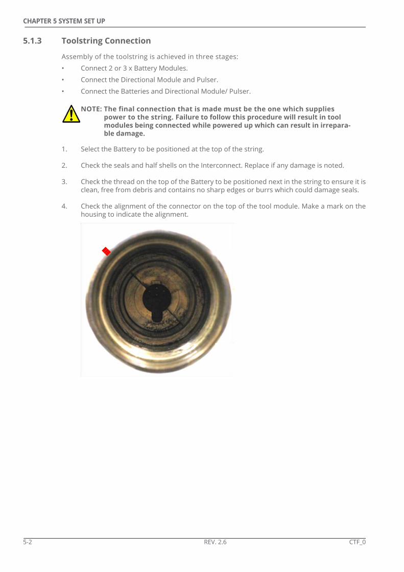
CHAPTER 5 SYSTEM SET UP
5.1.3 Toolstring Connection
Assembly of the toolstring is achieved in three stages:
• Connect 2 or 3 x Battery Modules.
• Connect the Directional Module and Pulser.
• Connect the Batteries and Directional Module/ Pulser.
1. Select the Battery to be positioned at the top of the string.
2. Check the seals and half shells on the Interconnect. Replace if any damage is noted.
3. Check the thread on the top of the Battery to be positioned next in the string to ensure it isclean, free from debris and contains no sharp edges or burrs which could damage seals.
4. Check the alignment of the connector on the top of the tool module. Make a mark on thehousing to indicate the alignment.
NOTE: The final connection that is made must be the one which supplies power to the string. Failure to follow this procedure will result in tool modules being connected while powered up which can result in irrepara-ble damage.
5-2 REV. 2.6 CTF_0

CHAPTER 5 SYSTEM SET UP
5. Check the alignment of the connector on the bottom of the Interconnect. Make a mark onthe non-rotating central shaft of the Interconnect (under the spring) to indicate the align-ment of the connector.
6. Secure the lower Battery Module on tool stands with a frictions wrench to stop it formrotating.
7. Screw the module onto the Interconnect until the O-ring on the Interconnect is reached.
8. Back off the connection slightly and align the marks on the module and the Interconnect.
CTF_0 REV. 2.6 5-3

CHAPTER 5 SYSTEM SET UP
9. Secure the upper Battery with a friction wrench.
10. Tighten the connection using the Pin Wrench on the Interconnect.
11. Repeat to connect the third Battery to the bottom of the string.
12. Lay the Battery assembly to one side.
13. Connect the DIrectional Module to the Pulser as described above.
14. Align the Battery assembly with the Directional Module/ Pulser and connect as describedabove.
The Toolstring can now be programmed with an operating configuration.
NOTE: The last connection that is made must be the one that will apply power to the string.
5-4 REV. 2.6 CTF_0

CHAPTER 5 SYSTEM SET UP
5.2 Tool Programming
The MWD toolstring, Centerfire and Surface System need to be programmed to ensure thecorrect data is transmitted to surface and successfully decoded. The qMWD ConfigurationUtility is used to create and manage tool configurations which are then loaded to the systemwhen the string is connected on the drillfloor. Configurations can be created or editedwithout connection to the system by working in offline mode. Offline mode willautomatically operate if the PC does not recognise any part of the tool as being connected.
NOTE: The configuration must be loaded to the Centerfire after connection of the MWDstring on the drill floor.
The following warning will be displayed if the software does not recognise a DirectionalModule. If no DM is present then the user must ensure the configuration is loaded to the DMbefore the run begins.
For information on the use of the qMWD Configuration Utility the operator should referencethe MWD Operator Manual and the embedded help file within the utility.
It is good practice to load the Configuration to the MWD Toolstring while on deck to ensureall communication and connections are good. Refer to Section 6.5.8 for information onConfiguration Loading.
NOTE: For a 2-Bay DM only Nodes 5, 20 will be available when communicating withoutconnection to the Centerfire Collar. For a 3-Bay DM only Nodes 5, 20 and 21 will beavailable.
Centerfire-specific information and set-ups, not detailed in the MWD Operator Manual, aredetailed below.
CTF_0 REV. 2.6 5-5

CHAPTER 5 SYSTEM SET UP
5.2.1 Nodes
The Centerfire system is assigned Node 23 but as it automatically broadcasts its data it notneed be identified as the source of any data that it will supply during a Survey Sequence orToolface/ Logging Sequence when using a 2-bay Directional Module. This is true for bothresistivity data and gamma data.
NOTE: NEVER use any Node addresses when using a 2-bay Directional Module.
When using a legacy 3-bay Directional Module it is necessary to specify the Node from whichthe Centerfire data is sourced. To specify a Node it must be named in the configuration. Nodenames are identified by being surrounded by “\”s.
Consider the following simple Toolface/ Logging Sequence:\21\|aTFA:6:P|;\23\|Gama:8:P CCP2:8:P|
This directs Node 21 (DGS) to supply the toolface data and the Node 23 (Centerfire) to supplythe Gamma and Resistivity (see below for information on resistivity data sets).
5-6 REV. 2.6 CTF_0

CHAPTER 5 SYSTEM SET UP
5.2.2 Resistivity Data Sets
Operators must decide which resistivity data sets to transmit to surface. This decision shouldmade after consultation with all interested parties at the rig site.
When deciding which data to transmit the following should be considered:
• The maximum expected resistivity should be estimated to allow required transmission resolution to be defined
• Only compensated data is available for transmission
• It is normal to transmit 2 or 3 data sets. More than 2 data sets could result in a lack of resolution of all Toolface/ Logging Data
• Attenuation should only transmitted when expected resistivities are low
• Measurements which offer very different depths of investigation are favourable
The Centerfire transmits values of Phase Difference [PD] or Attenuation (Amplitude ratio)[AT] in real time. As both PD and AT are inversely proportional to resistivity, the larger theresistivity of the formation the smaller the value that the CTF will transmit to surface. M-aryencoding requires that small values need a larger number of transmission bits. If insufficientbits are used to transmit the data, the calculated resistivity will lose resolution at the higherextremes before reaching the maximum resistivity value (the minimum resolved transmittedvalue) at which point the log will flat-line”.
Refer to Table 5-1 when selecting required transmission resolution.
Therefore, to transmit 19” 2MHz PD and 41” 400kHz AT in a formation with an expectedresistivity of 10 Ohm.m the following variables would be included in the Toolface/LoggingSequence:
• CCP2:9:P
• CCA3:14:P
CTF_0 REV. 2.6 5-7
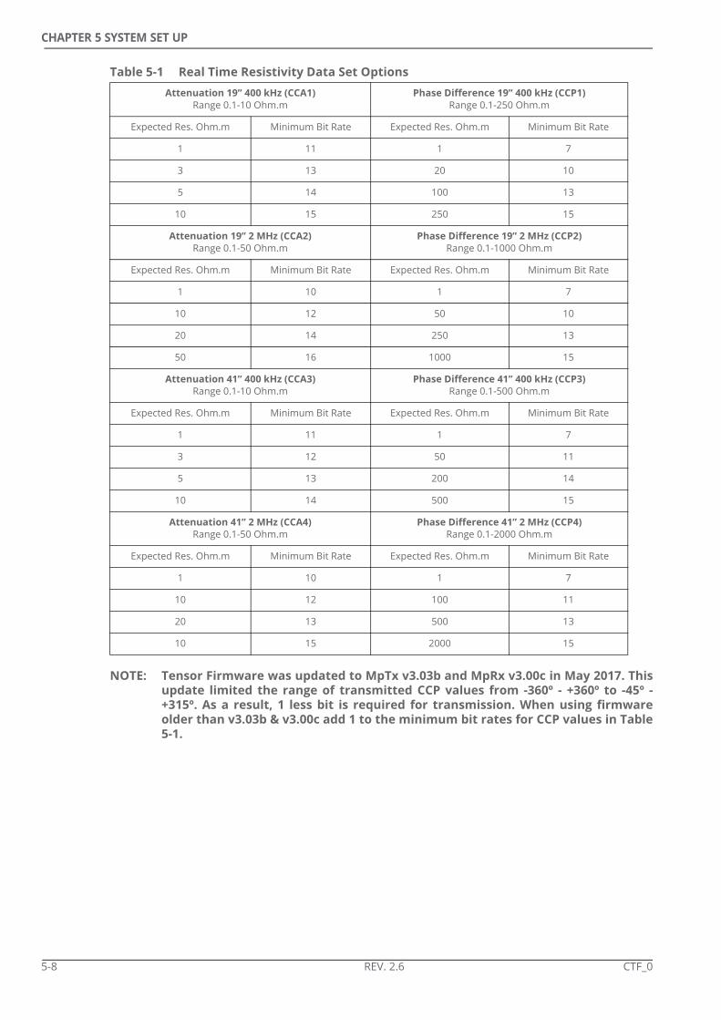
CHAPTER 5 SYSTEM SET UP
Table 5-1 Real Time Resistivity Data Set Options
NOTE: Tensor Firmware was updated to MpTx v3.03b and MpRx v3.00c in May 2017. Thisupdate limited the range of transmitted CCP values from -360º - +360º to -45º -+315º. As a result, 1 less bit is required for transmission. When using firmwareolder than v3.03b & v3.00c add 1 to the minimum bit rates for CCP values in Table5-1.
Attenuation 19” 400 kHz (CCA1)Range 0.1-10 Ohm.m
Phase Difference 19” 400 kHz (CCP1)Range 0.1-250 Ohm.m
Expected Res. Ohm.m Minimum Bit Rate Expected Res. Ohm.m Minimum Bit Rate
1 11 1 7
3 13 20 10
5 14 100 13
10 15 250 15
Attenuation 19” 2 MHz (CCA2)Range 0.1-50 Ohm.m
Phase Difference 19” 2 MHz (CCP2)Range 0.1-1000 Ohm.m
Expected Res. Ohm.m Minimum Bit Rate Expected Res. Ohm.m Minimum Bit Rate
1 10 1 7
10 12 50 10
20 14 250 13
50 16 1000 15
Attenuation 41” 400 kHz (CCA3)Range 0.1-10 Ohm.m
Phase Difference 41” 400 kHz (CCP3)Range 0.1-500 Ohm.m
Expected Res. Ohm.m Minimum Bit Rate Expected Res. Ohm.m Minimum Bit Rate
1 11 1 7
3 12 50 11
5 13 200 14
10 14 500 15
Attenuation 41” 2 MHz (CCA4)Range 0.1-50 Ohm.m
Phase Difference 41” 2 MHz (CCP4)Range 0.1-2000 Ohm.m
Expected Res. Ohm.m Minimum Bit Rate Expected Res. Ohm.m Minimum Bit Rate
1 10 1 7
10 12 100 11
20 13 500 13
10 15 2000 15
5-8 REV. 2.6 CTF_0

CHAPTER 5 SYSTEM SET UP
5.2.3 ReSR - Resistivity Status Register
The Resistivity Status Register is a function that can be added to a tool configuration whichwill direct the tool to transmit an indication of whether the tool is operating properly. Thefunction is important during operations as it will give warning of a problem downhole. It isalso useful in the workshop where it can help troubleshoot a tool. Information from the toolregarding the Status Register is configured to be transmitted in both the Toolface LoggingSequence and the Static Survey Sequence.
NOTE: With Centerfire Recorder Board Firmware V2.01J, or later, the ReSR word isincluded in every PRD memory file record.
5.2.3.1 Toolface Logging Sequence
It is recommended that a single transmission of ReNF be set at the end of the Toolface/Logging Sequence as a fault indicator. ReNF will return a 0 if the tool is fully operational anda 1 if any aspect of ReSR are in fault. No information on the nature of the fault is transmittedusing ReNF. If ReNF is seen to indicate a fault then the pumps can be cycled to get a surveywhich will include the diagnostic information in the ReSR word.
5.2.3.2 Static Survey Sequence
To determine the nature of a fault ReSR is required. It is recommended that ReSR is includedat the end of every Static Survey Sequence. The ReSR word is not decoded by qMWD butinstead displayed as a 4 digit binary word. Refer to Section 12.5.5 for more information ondecoding the ReSR data word. Alternatively, an ReSR Decoder Spreadsheet can bedownloaded from the Technical Support Portal at:
www.tensordt.com
CTF_0 REV. 2.6 5-9

CHAPTER 5 SYSTEM SET UP
5.3 qMWD Configuration Utility
5.3.1 General Setups
General configuration setups for a Centerfire job:-.
1. Open the QMWD folder on the desktop of the QMWD laptop and start the qMWD Con-figuration Utility
2. The software version window for the qMWD Configuration Utility will appear andrequest an access code. Type in 99 for the Capability Code.
5-10 REV. 2.6 CTF_0

CHAPTER 5 SYSTEM SET UP
3. The Open Configuration window will appear with a list of saved configurations. SelectDefault 2-Bay or Default 3-Bay for initial configuration.
4. The program will now poll the qMWD network to see which boards are connected tothe qMWD network.
The following warning will be displayed if no Directional Module is recognised.
CTF_0 REV. 2.6 5-11

CHAPTER 5 SYSTEM SET UP
5. The Online Node and Firmware Status window will then appear.
• The Online Node Status must display the correct nodes connected to the system:Receiver - SAI, Node 5Transmitter - DM MPU, Node 20Directional-Gamma - DM DGS, Node 21 (3-Bay DM only)Resistivity - Centerfire, Node 23
• The Surface System Firmware must be V02.00+ 2-Bay or 3-Bay Compatible• The Downhole Tool Firmware will show the DM Firmware and it must be Resistivity
Compatible.
6. Once fields are confirmed, click OK button to get to the MWD Configuration window.
5-12 REV. 2.6 CTF_0

CHAPTER 5 SYSTEM SET UP
7. In the MWD Configuration window, click on Setup and select Operating Parameters.
8. In Operating Parameters for rig operations:a) Enable - Auto Verify and PWR Controlsb) Disable - Gamma Steering and Offline Mode Control
9. Click the Close button, and the program will ask if you want to save setup. Click Yes.
The telemetry sequences for Centerfire Gamma-Resistivity logging are now set.
CTF_0 REV. 2.6 5-13

CHAPTER 5 SYSTEM SET UP
5.3.2 Telemetry Controls
A system configuration based on the Centerfire logging tool must be set up. This includes theTelemetry sequences which are accessed through the MWD Configuration window.
Telemetry Controls is used to configure the telemetry setting for the surface receiver anddownhole MWD system.
• Receive Delay Time - informs the surface receiver how long to wait before accepting pulse data from the pressure sensor. The default is 30 seconds; set a value based upon how long it will take for the pumps to reach the desired flow rate.
• Transmit Delay Time - informs the MWD tool how long to wait before transmitting the survey.• the default is 60 seconds, set value based upon how long it will take for the
pumps to reach the desired flow rate• the values for Receive and Transmit Delay Time can not be the same. There must
be a minimum 5 second difference between each
5-14 REV. 2.6 CTF_0

CHAPTER 5 SYSTEM SET UP
• Resync Control - enables the user regain sync after it is lost - enable for Centerfire operations
• Downlink Commands - enables the user to downlink to the system to change configuration - these are usually disabled for Centerfire operations.
• Inclination Threshold - determines at what inclination to switch between magnetic toolface and gravity toolface - leave at default. If it must be changed the minimum value to change for accurate gravity toolface is 3 degrees.
• Leave remaining fields at default values.
5.3.3 Special Telemetry Controls
These controls handle the MWD telemetry sync word format and transmission pulse widths.
Sync Word Type/Format - enables the user to set which sync word format to use - forCenterfire operations select 3111.
Leave the remaining fields at default.
CTF_0 REV. 2.6 5-15

CHAPTER 5 SYSTEM SET UP
5.3.4 Mode Control Settings
This control is used to set the pulse width, survey sequence, and toolface-logging sequencethat will be used for the drilling run.
• Mode Number - sets which combination of pulse width, survey sequence, and toolface-logging sequence to use for the drilling run. There are 4 mode numbers that can be used. Changing between mode numbers is only applicable for downlinking.
• Pulse Width - sets the data transmission rate for the MWD tool - the fastest pulse width that can be used is 0.5 seconds. Pulse width chosen is dependant on expected ROP and data to be transmitted.
• Survey Sequence - sets which survey sequence from Survey Sequence Definitions to use.
• T/L Sequence - sets which toolface-logging sequence from Toolface-Logging Sequence Definitions to use.
Once set click the Close button.
5-16 REV. 2.6 CTF_0

CHAPTER 5 SYSTEM SET UP
5.3.5 Survey Sequence Definitions
This control is used to set which directional measurements are to be sent as a survey.
• The user has 4 different survey sequences that can be configured. This is used only when downlinking is planned.
• For Survey Sequence #1, the following is a standard survey sequence used for Centerfire operations:Inc:11:P Azm:12:P DipA:11:P MagF:12:P Grav:12:P Temp:8:P BatV:8:P ReSR[]
NOTE: This sequence is designed for use with a 2-Bay DM which does not require Node 20to be identified. For a 3-Bay tool Node 21 must be identified. Refer to Section 5.2.1.
• Leave the other survey sequence number fields at default.
• Click the close button.
CTF_0 REV. 2.6 5-17

CHAPTER 5 SYSTEM SET UP
5.3.6 Toolface Logging Sequence Definitions
This control is used to set which directional and logging measurements are to be sent in realtime when the tool is in sliding or rotary mode.
NOTE: Toolface/ Logging sequences must be agreed with the end users of the data beforethe system is configured.Refer to Section 5.2.2 for information on the data sets which can be transmitted bythe Centerfire system.
• The user has four different sequences that can be configured. Only 2 will need to be used for Centerfire operations.
• For T/L Sequence #1, the following is a standard sequence for Centerfire operations with a 2-Bay DM when the tool is in sliding mode:20 {aTFA:6:P; Gama:8:P; CCP2:10:P; aTFA:6:P; Gama:8:P; CCP4:10:P; RotW} BatV:8:P ReNF Temp:8:PFor a 3-Bay DM Node 21 will need to be identified for steering data:20{\21\aTFA:6:P;\23\|Gama:8:P; CCP2:10:P|;\21\aTFA:6:P;\23\|Gama:8:P; CCP4:10:P|; \21\RotW} BatV:8:P ReNF Temp:8:P
• For T/L Sequence #2, the following is a standard sequence for Centerfire operations with a 2-Bay DM when the tool is in rotary mode: 15{Gama:8:P; CCP2:10:P; CCP4:10:P; RotW} ReNF BatV:8:P Temp:8:PFor a 3-Bay DM Node 21 will need to be identified for steering data:15{\23\|Gama:8:P; CCP2:10:P; CCP4:10:P|\21\RotW:P} ReNF BatV:8:P Temp:8:P
• Leave the other T/L sequence numbers at default.
• Click the Close button.
Refer to the Appendix for more information on tool programming including data variables,measurement components, sequence syntax, node addresses and hexadecimal numbering.
5-18 REV. 2.6 CTF_0

CHAPTER 5 SYSTEM SET UP
5.3.7 Job Site environmental Settings
This control is used to configure the job location geomagnetic settings for both the SAIreceiver and the MWD tool:
1. Site Location - is the name of the location for the job.
2. Nominal Dip Angle - a survey quality control factor used to determine if the surveymeasurement has been affected by external factors.
3. Dip Angle Tolerance - the amount of deviation allowed from the nominal dip anglewhen surveys are received from the MWD tool. This is client defined. Otherwise use thedefault setting.
4. Nominal Magnetic Field - a survey quality control factor used to determine if the surveymeasurement has been affected by external factors.
5. Magnetic Field Tolerance - the amount of deviation allowed from the nominal magneticfield when surveys are received from the MWD tool.
NOTE: This value is obtained from the drilling program, directional driller or oil company representative on site. THIS VALUE MUST BE AGREED UPON BY ALL PERSONNEL ON-SITE WHO ARE RESPONSIBLE FOR THE WELL TRA-JECTORY. Failure to use the correct number will cause significant errors in the well trajectory.
NOTE: This value is obtained from the drilling program, directional driller or oil company representative on site. THIS VALUE MUST BE AGREED UPON BY ALL PERSONNEL ON-SITE WHO ARE RESPONSIBLE FOR THE WELL TRA-JECTORY. Failure to use the correct number can lead to erroneous sur-vey results being accepted and resultant errors in wellbore trajectory.
CTF_0 REV. 2.6 5-19

CHAPTER 5 SYSTEM SET UP
6. Magnetic Declination - a factor used to correct magnetic azimuth and magnetic tool-face.
7. Nominal Gravity Magnitude - a survey quality control factor used to determine if thesurvey measurement has been affected by external factors - leave at default. Whenreceiving surveys an acceptable value is 0.995 to 1.005 g.
8. Leave the remaining fields at default.
5.3.8 Directional Processing Controls
This control enables the user to edit and observe the variables relating to the MWD tooldirectional processor.
High Temperature Threshold - this is the only parameter that should be edited in this control.This sets the temperature threshold in degrees Celsius at which to flag when the MWD tool isexperiencing a downhole temperature higher than the threshold.
NOTE: This value is obtained from the drilling program, directional driller or oil company representative on site. THIS VALUE MUST BE AGREED UPON BY ALL PERSONNEL ON-SITE WHO ARE RESPONSIBLE FOR THE WELL TRA-JECTORY. Failure to use the correct number will cause significant errors in the well trajectory.
5-20 REV. 2.6 CTF_0

CHAPTER 5 SYSTEM SET UP
5.3.9 Dynamic T/L Sequence Change Controls
This control is used to enable the user to configure the MWD tool to transmit a toolface-logging sequence from Toolface-Logging Sequence Definitions based upon the drilling mode(sliding or rotary mode). Drilling mode is determined by the MWD tool based upon the RPMmeasured from its RPM sensor.
1. Dynamic T/L Sequence Change Enable - determine if dynamic sequencing should be used -set this to Enable.
2. Non-Rotating - this parameter asks the user which toolface-logging sequence fromToolface Logging Sequence Definitions to use when the current drilling mode is sliding.
3. Rotating, Uniform and Non-Uniform Gamma Field - this parameter asks the user whichtoolface-logging sequence from Toolface Logging Sequence Definitions to use whenthe current drilling mode is rotary.
4. Rotating Rate Threshold - sets the RPM threshold to use to determine whether thedrilling mode is rotary or sliding.
5. While Rotating Update Time - how often to check the current RPM experienced by thetool
6. The remaining fields leave at default.
CTF_0 REV. 2.6 5-21

CHAPTER 5 SYSTEM SET UP
5.3.10 Battery Processing Controls
This control is used to handle the battery power supply measurement.
1. Voltage Update/Averaging Time - how often to check the current battery voltage andaverage the measurement to store in memory
2. Low Battery Voltage - battery voltage threshold that sets the low battery voltage flag ifthe measured battery voltage is below the threshold.
3. Leave remaining fields at default.
5.3.11 Pumps Flow Evaluation Controls
This control handles the SAI receiver pressure and MWD tool flow sensing controls.
1. Pumps On Threshold - configures SAI receiver to determine when to change pumps onor off state.
2. Pressure Transducer Rating - sets the pressure rating for the pressure transducer used.
3. Pressure Transducer Offset - used to align the pressure transducer reading with thepressure measurement from the driller's standpipe pressure gauge.
5-22 REV. 2.6 CTF_0

CHAPTER 5 SYSTEM SET UP
4. Flow On-Off Evaluation Time - sets how often the MWD tool checks flow on-off statuswith its flow sensor.
5. Invert Flow Switch Sense - used for shop testing only - this MUST be set to OFF for drill-ing.
6. Short Flow Off Time - set to 0
7. Short Flow-Off Surveys - set to No.
8. Leave remaining fields at default.
5.3.12 Surface Receiver Controls
The parameters within this control can also be changed in the Basic Receiver Control sectionof the QMWPC software. This handles the MWD signal pulse limits and data quality checks.
1. Low Pulse Amplitude Limit - sets the threshold for the smallest MWD pulse amplitudeaccepted for use by the SAI receiver.
2. High Pulse Amplitude Limit - sets the threshold for the largest MWD pulse amplitudeaccepted for use by the SAI receiver.
5.3.13 Depth Tracking Controls
The parameters within this control can also be changed in Depth Tracking Control in theQMWDPC software. This control handles the depth tracking parameters during the job.
1. Depth Tracking Mode - requests how the depth will be tracked• Off - used when depth will be provided from an outside WITS source or no depth
tracking will be provided at all• Manual - used when a depth sensor is used but no hookload sensor• Automatic - used when both a depth sensor and hookload sensor are to be used
to track in-out slips state
2. On Bottom Detection Method - requests how the SAI receiver will determine if the toolis on bottom drilling.• Bit depth or hookload weight are the options• Select Depth based for Centerfire operations
3. Depth Tracking Sensor Type - what type of depth sensor will be used to track bit depth- select Draw works for Centerfire operations. Geolograph is not supported.
CTF_0 REV. 2.6 5-23

CHAPTER 5 SYSTEM SET UP
4. In Slips Travel Distance - how much difference between the bit depth and hole depth isrequired to confirm the BHA is in slips. This stops the system inadvertently entering an“In-Slips” state when the drill string is light or drilling is horizontal.
5. Off Bottom Travel Distance - maximum difference between Bit Depth and Hole Depthbefore and Off Bottom state is recognised.
6. Leave remaining fields at default.
5.3.14 PWR Processing Controls
When using Centerfire the operator must configure two settings which control its operation.These are located in the Resistivity Processing Controls window.
• Recorder Delay - The time (in minutes) between the tool being powered up and starting to write to memory. This is usually used if a long trip to bottom is expected. It should always be set conservatively to ensure the tool is logging to memory when drilling begins.
NOTE: A surface/ shallow test is not possible if a recorder delay is set to stop transmissionwhile running in to the hole. Set the Recorder Delay to zero (0) if the customerrequires shallow test data from the Centerfire tool.
Recorder Delay is not often needed as the amount of memory available is usually longerthan the life of the batteries. Typical recorder lengths are >250 hrs with 1 second DeadTime, >2000 hrs with 60 second Dead Time.
• Dead Time - Time (in seconds) inserted between each measurement. In normal MWD mode the tool will record a set of data every 9 seconds (every 1.8 seconds in Trip Out mode). When drilling is slow Dead Time can be inserted to save battery life.
NOTE: Dead Time is a required entry in the Battery Life Spreadsheet (see Section 4.3.1.)
The Gamma High Limit for Pulsing [GaHL] variable should be changed where high gammavalues are expected. It is necessary to match the number of telemetry bits in the Toolface/Logging Sequence (see Section 5.3.6) to the value displayed in the GaHL field.
The other Gamma Processing Controls should not be changed.
5-24 REV. 2.6 CTF_0

CHAPTER 5 SYSTEM SET UP
5.3.15 Saving Tool Configuration
Once the user has completed setting up the MWD program configuration, it must be saved.
1. File > Save Configuration
2. The Save As window will appear. Type in the name the user wishes to save the configu-ration as.
3. Click the save button and the configuration will be stored in the MWD Configurationdatabase.
CTF_0 REV. 2.6 5-25

CHAPTER 5 SYSTEM SET UP
4. To program the SAI receiver and directional module, use the Load/Store function. Thetool will be programmed on the rig floor.
5. Load/Store > Store To. The qMWD network nodes will be polled and the Store To win-dow will appear.
NOTE: Only the nodes that are currently connected and communicating in the QMWDnetwork can be programmed with the saved configuration.
6. Select Receiver, Transmitter, and Directional-Gamma.
5-26 REV. 2.6 CTF_0

CHAPTER 5 SYSTEM SET UP
NOTE: The Directional-Gamma board is only seen with 3-Bay DMs.
7. Click ‘OK’.
8. Click ‘Save’
9. The Store To function will then program the configuration to each node selected in theStore the Configuration window.
10. Once a node has been programmed with the configuration the user will be notified:-
CTF_0 REV. 2.6 5-27

CHAPTER 5 SYSTEM SET UP
11. Check that the configuration has been stored into a node using the Load From function:-
12. qMWD network nodes will be polled again and the Load From window will appear:-
• The configuration can be downloaded one node at a time• Select the node using the check boxes• Notification will appear when the configuration has been read• A name must be selected for the downloaded configuration• The configuration can be printed out by selecting various options• The output can be printed or converted to a PDF format with a PDF writer
installed
13. Export the Configuration for future use: File>Export Config. This allows configurationsto be transferred from one computer to another and re-used with File>Import Config.
14. File > Exit.
15. Conduct TFO Procedure now? Click No.
16. Repeat the MWD Configuration Utility steps in order to program the backup MWD tool-string and SAI receiver.
5-28 REV. 2.6 CTF_0

CHAPTER 5 SYSTEM SET UP
5.4 Toolface Set Up
After loading a configuration to the system the user is prompted to set the internal toolfaceoffset. This procedure will calculate the offset that is required to be applied tomeasurements made in the Directional Module so that they are referenced to the MuleshoeKey way in the Pulser Bottom end.
Refer to the MWD Operator Manual, pages 129 - 141, for the full Toolface Offsetprocedure for the MWD tool (Pulser - DM - BATTx3).
5.4.1 MWD Tool Scribing
The MWD tool must be marked to allow easy insertion into the Centerfire Muleshoe on thedrill floor.
1. Keep the MWD toolstring in the same position as was used in the Toolface Set Up proce-dure (helix keyway pointing upwards).
2. Using an indelible marker or paint pen make a mark on each tool module to indicate theposition of highside.
3. MAKE SURE THE HIGHSIDE IS MARKED ON THE PART OF THE TOOL THAT STICKS UPOUT OF THE MAIN MWD DRILL COLLAR.
NOTE: FAILURE TO FOLLOW THIS PROCEDURE CORRECTLY WILL RESULT IN THE WELL BEING STEERED IN THE WRONG DIRECTION
CTF_0 REV. 2.6 5-29

CHAPTER 5 SYSTEM SET UP
5.5 Battery Jumper Installation
The Interconnect, Battery Jumper and Spearpoint must be placed on top of the UpperBattery before the tool is sent downhole.
NOTE: Failure to install the Battery Jumper will result in an accelerated drain on the bat-teries.
1. Connect the Interconnect to the top of the upper Battery.
2. Install the Battery Jumper (981524) on top of the Interconnect.
NOTE: Failure to install the Battery Jumper will result in accelerated drain on the batter-ies.
3. Install the Spearpoint over the Battery Jumper and torque using friction wrenches.
5-30 REV. 2.6 CTF_0

CHAPTER 5 SYSTEM SET UP
5.6 Measurement Offsets
For every run the sensor offsets need to be calculated and entered into LogView in the LogPlot Data window. Refer to Section 7.2.5 for more information on the set up of offsets inLogView II.
NOTE: A Centerfire Operational Calculations Spreadsheet which will calculate sensor off-sets can be downloaded from the Technical Support Portal at: www.tensordt.com.
CTF_0 REV. 2.6 5-31

CHAPTER 5 SYSTEM SET UP
5.6.1 Measurement Datums - Centerfire Tools
The following figure and tables outlines the measurement datums for the Centerfire tool.
Figure 5-1 Measurement Datum, Centerfire Tool
AMuleshoe Anchor Bolts B
Resistivity Measurement Point C
Collar Connec-tion D Gamma Measurement Pointa
a. 8.25” tools have internal gamma sensors. The measurement point is 14.88” (37.8 cm) up from the bot-tom of the tool.
II
III
B
D
C
not drawn to
A
I
IV
V
5-32 REV. 2.6 CTF_0

CHAPTER 5 SYSTEM SET UP
Table 5-2 Centerfire Collar Lengths and Measurement Points
5.6.2 Directional Survey Offset.
The calculation of the directional survey offset requires length I from Figure 5-1 and thedistance from the datum (Muleshoe Anchor Bolts/ bottom of Pulser) on the MWD string tothe directional survey measurement point to be known.
For the recommended configuration of the MWD string when running Centerfire (Pulser,Directional Module, Battery 2, Battery 1, Battery 3) the distance from datum to measurementpoint is 137.45” (3491 mm). For other configurations of the MWD string use the lengths inTable 5-3 to calculate the datum to measurement point.
The measurement point is 1.60 feet (492 mm) up from the bottom of the Directional Module.
Figure 5-1 Definition 4.75” 6.91” 8.25”
I Top Collar - Muleshoe Anchor Bolts45.185” (1148 mm)
45.935” (1167 mm)
45.935” (1167 mm)
IIBottom Centerfire Collar to Resistivity Measurement Point
73.25” (1861 mm)
73.00” (1854 mm)
80.87” (2054 mm)
III Collar Connection to Gamma Measurement Point26.98” (686 mm)
23.76” (604 mm) N/A
IV Gamma Collar Lengtha8.32 ft (2.53 m)
8.27 ft (2.52 m) N/A
V Centerfire Collar Length14.5 ft (4.42 m)
14.5 ft (4.42 m)
15.16 ft (4.62 m)
a. Not applicable to 8.25” tool
CTF_0 REV. 2.6 5-33

CHAPTER 5 SYSTEM SET UP
Table 5-3 Tool Module Lengths
To calculate the distance from the Bit to the Sensor point the distance from Bit to Datummust be calculated:
Bit to Datum = Bit to Top Centerfire Collar - Length I (Figure 5-1)
Bit to Directional Sensor = Bit to Datum + Datum to Directional Sensor
Tool Module Length (inches/ mm)
Centerfire Pulser 102.75 / 2610
2-Bay Directional Module 79.80 / 2026
3-Bay Directional Module 89.75 / 2280
Gamma Module 62.40 / 1535
Battery Module 70.00 / 1778
Interconnect 14.06 / 357
5-34 REV. 2.6 CTF_0

CHAPTER
RIG FLOOR PROCEDURES
6.1 Introduction
All the downhole tool components should be checked in accordance with the proceduresstated in their manuals prior to the MWD Toolstring being assembled and the Bottom HoleAssembly [BHA] being assembled on the rig floor.
NOTE: The Gamma Module in the 4.75” and 6.91” tools is usually connected in the work-shop before the Centerfire collar is transported to the rigsite. In situations whenit is necessary to replace the Gamma Module at the rigsite refer to Section 12.6,“Gamma Module Replacement”.The Gamma Module should NOT be replaced onthe rigfloor
CTF_0 REV. 2.6 6-1

CHAPTER 6 RIG FLOOR PROCEDURES
6.2 Weather Extremes
Extremes of weather conditions bring their own special conditions or procedures for theoperator to consider.
NOTE: ATEX Zone 1 certification does not apply at temperatures below -20°C or above+45°C.
6.2.1 Hot Climates
The operator should be aware of the following when working in hot climates:-
Procedures for racking-back the tool (see Section 9.3).
Protection for the Driller’s Remote Terminal: if the display is left uncovered in the full heat ofthe sun, the display may, after a period of time, be affected (the display is rated for -20°C to+45°C). Repeated cycles of hot and cold may permanently damage the display.
If the collar or MWD tool sections are left outside in the sun, the metal surfaces will becomevery hot and could cause a burn when touched.
Battery packs and spare cartridges should be stored in a cool (0°C - 25°C), NOT cold, dryenvironment.
6.2.2 Cold Climates
Just as with very hot conditions, extreme cold can cause problems unless the operator isaware of the dangers:-
Racking-back the tool (see Section 9.3).
6.2.2.1 Surface System
The Laversab DDU has a Liquid Crystal Display that, in extremely cold conditions, couldfreeze (the display is rated to -20°).
Fluid in the Standpipe Pressure Sensor may freeze during periods of no circulation.
6.2.2.2 MWD Toolstring
ALL the MWD tool components should be kept in a warm environment until the last possiblemoment before being taken to the rig floor. The reason for this is that the elastomer sealsused in the tools will harden and shrink if left to get too cold. Hard seals are difficult to workwith and damage easily, and seals that have contracted due to the cold may no longer sealcorrectly within the bore of the pressure housings. An alternative to keeping the tools in theMWD cabin until the last moment is to steam them (making sure steam is not allowed to getto the internal assembly) prior to making up the tool.
NOTE: The toolstring can be assembled and tested before being broken to smaller sec-tions for storage in a warm environment. It is critical that the Bottom End remainstorqued to the Pulser to maintain an accurate TFO angle.
Seals should be warm when being installed. Similarly, the component onto which the seal isbeing installed should be warmed prior to installation.
The Male Wet Connect can be dressed with Arctic temperature o-rings in extremely lowtemperatures, < -26ºC/ -15ºF, (see Section 4.5).
6-2 REV. 2.6 CTF_0

CHAPTER 6 RIG FLOOR PROCEDURES
Batteries should be kept warm and will need to be thoroughly depassivated before use toensure they supply sufficient power to the system. Depassivation is achieved by applying aload to the battery power circuit using:
• a dedicated battery de-passivator (non-Tensor DT)
• a 220 Ohm 10W resistive circuit
• a Directional Module connected to the battery
If batteries have been stored at a low temperature then they will need more depassivation toachieve a working, or loaded, voltage of >26.0 V.
When handling the metal housings, always use gloves to stop skin sticking to the metal.
During loading of the toolstring into the NMDC the tool temperature may fall considerably.This could affect the batteries ability to power the string thus affecting the quality of theshallow hole test. Continued circulation of warm mud will, however, warm the tool to a levelat which a successful shallow hole test will be achievable.
6.2.2.3 Centerfire Collar
Seals
Standard seals used in the Centerfire Collar are not rated for very low temperatures. The toolmust be dressed with Arctic O-rings if exposed to temperatures below -26ºC / -15ºF for anyextended period of time. Details of Arctic O-rings kits are found in Section 7 of the CenterfireMaintenance Manual.
NOTE: Collar seals should only be replaced in a clean workshop environment by trainedtechnicians.
When stored in temperatures below 0ºC / 32ºF the collar should be warmed before exposingto drilling fluid. The use of heating blankets or the gentle use of steam guns allow the collarto be brought up to temperature, thus ensuring the seals are pliable enough to perform asdesigned.
Collar Cleaning
It is critical that the internals of the Collar are as clean as possible. The female Wet Connect,Muleshoe and upper bore must be perfectly clean and free of ice before installation of theMWD toolstring. Prior to BHA make-up, the Centerfire should therefore be thoroughlycleaned. Similarly the NMDC, which is run above the Centerfire, should be as clean aspossible to prevent contamination entering the critical areas of the Centerfire.
Testing
When deck testing the Centerfire, care should be taken of the O-ring on the Dump PortCover. Ideally the Collar should be warmed before removal of the Cover, and then theassembly should be re-warmed before re-installation of the Cover. As with all O-rings, theseal will deform in its designed manner if it is warm and pliable. Care should also be taken ofthe POD Cable during deck testing. The rubber shroud on the Collar connection can becomebrittle and hard to handle at low temperatures. Warming it will make connection mucheasier. Do not store POD cable outside
Tool Response
The Centerfire collar gives standard responses at extremely low temperatures. Variance inresponse will be noted if the tool is rapidly changing temperature. This is true at high
CTF_0 REV. 2.6 6-3
CHAPTER 6 RIG FLOOR PROCEDURES
temperatures also. Allow the tool to stabilise in temperature before assessing the stability ofthe responses.
Making Up to BHA
When making the Centerfire to the BHA it is critical that the threaded connections arethoroughly warmed, using a steam gun for up to 15 minutes, before applying any torque.Note that with any new threads, the “quarters” method should be used when torquing theCenterfire collar for the first time, This sees ¼ of the final torque being applied and broken,then ½ of the final torque being applied and broken. ¾ of the final torque is then applied andbroken before the thread is made up to its final torque value.
MWD String Seating
• Stick Up - Calculate the expected to stick up allow the correct seating point to be identified easily.
• Scribe the NMDC - The orientation of the Muleshoe Key in the Centerfire Collar should be scribed to the top of the NMDC. When installing the MWD toolstring the alignment to the scribe line should be maintained to minimize any rotation when the toolstring seats.
• Prepare the Male Wet Connect - The Wet Connect on the Pulser must be perfectly clean and should be kept warm up until the point the tool is inserted into the NMDC. Again warm O-rings will deform much more easily allowing seating to be achieved more easily.
• Check Battery Voltages - After installation of the MWD, the system is programmed and set up for downhole use. At this point, at extremely low temperatures, the batteries may have cooled to the point where they struggle to power to the whole system. This can be noted by checking either BatV on Node 20 or RBLo on Node 23. If these voltages are seen to be excessively low (<20 or 18V respectively) the tool may not be powered correctly and other errors may be seen. The safest way to heat the batteries at this point is to run into hole enough for the circulating head to be installed and for mud to then be pumped across the tool. The length of time that circulation will be required depends on the temperature of the surface mud system but 5 minutes should be suitable, at which point the system can be pulled back to the rotary table and programmed/ set up.
6-4 REV. 2.6 CTF_0

CHAPTER 6 RIG FLOOR PROCEDURES
6.3 Rig Floor Safety
On any drilling installation, the most hazardous place is the rig floor and since MWDoperators work there frequently, they should be aware of the basic rules:-
• Wear a hard hat, safety glasses and safety boots (minimum requirement) during all operations outside the MWD cabin.
• Discuss tool handling and makeup procedures with the driller before the operations start.
• Be aware that drilling tubulars are very heavy and are dangerous when swinging in the derrick.
• Give clear hand signals when required to do so to direct a crane or fork-lift driver or the driller on the rig floor.
• Do not stand between the driller and the hole when assembling the tool. It is very important that the driller has a clear view of all that is going on.
• Allow the roustabouts and roughnecks to do their job; it is not the MWD operators job to handle the rig tongs or lifting equipment.
• When assembling the tool on the rig floor, as few people as possible should be involved.
• Do not spend more time on the rig floor than is necessary to complete tool assembly or disassembly.
CTF_0 REV. 2.6 6-5

CHAPTER 6 RIG FLOOR PROCEDURES
6.4 Tool Handling Considerations
Rig site personnel must be made aware of the sensitive areas of the Centerfire collar. Thefollowing points should always be explained:
• Where possible the Centerfire should be lifted horizontally to the rig floor.
• The tool should not be dragged up from the cat walk to the drill floor.
• Every precaution should be taken to ensure Antennae and Hatch Covers are not damaged during tool handling.
• Tongs should only be placed at the ends of the collar:• Above the Wet Connect Anchor Bolts at the top of the collar.• Below the Gamma Centralizer Anchor Bolts/ Hatch Cover at the bottom of the tool.
• Refer to Section 2 for torque specifications to be used when making up the collars.
6-6 REV. 2.6 CTF_0

CHAPTER 6 RIG FLOOR PROCEDURES
6.5 Drill Floor Tool Assembly
The Centerfire is connected to the MWD string on the drill floor. The following steps arecompleted during assembly:
1. Make up a Float Sub with a Float Valve (or non-return valve) installed to the BHA belowwhere the Centerfire collar will be located.
2. Lift Centerfire to drillfloor and connect to BHA.
3. Connect MWD Collar to Centerfire.
4. Lift MWD string to drillfloor and insert into MWD Collar.
5. Test connection between Centerfire and MWD string.
6. Remove the Float Sub from the BHA if it is not required for operations.
7. Clear memory and program system.
8. Perform shallow hole test.
NOTE: The Float Valve must be positioned below the Centerfire collar during make up ofthe Centerfire system. As the BHA is lowered to allow insertion of the MWD tool-string the female Wet Connect in the Centerfire collar may be below the mud line.Use of a Float Valve will prevent mud ingress into the Wet Connect. After the MWDtool has been inserted the Float Sub can be removed if it is not required.
6.5.1 Wet Connect Preparation
It is crucial that the Female Wet Connect in the Centerfire collar is free from any debris thatcould damage the Male Wet Connect upon insertion. The following steps should be taken ifthe tool is lifted to the rig floor or is used after having been racked back in the derrick.
1. Use a spray gun to clean any mud or debris from the assembly.
NOTE: The Wet Connect should be thoroughly flushed after every trip to stop any muddrying in the assembly.
2. Use a steam gun to remove any frozen mud or water.
CTF_0 REV. 2.6 6-7

CHAPTER 6 RIG FLOOR PROCEDURES
6.5.2 Lift Centerfire to Drillfloor
1. Check whether the Gamma Sub on the bottom of the 4.75” and 6.91” Centerfire tools havebeen torqued.
2. Install lifting caps on both ends of the collar. Lifting straps are not recommended.
3. Lift the tool horizontally to the drill floor. Ensure the lifting straps are not positioned overthe antennas if they are used.
4. Make up the Centerfire Collar (and Gamma Sub for 4.75” and 6.91” tools) to the BHA below.Refer to Section 2 for details on torque to be applied to the connections.
6-8 REV. 2.6 CTF_0

CHAPTER 6 RIG FLOOR PROCEDURES
6.5.3 Calculate the Drill Assembly Offset [DAO]
The offset between the motor and the scribe line of the Centerfire system must be calculatedand entered into the surface system.
NOTE: Failure to enter the correct DAO will result in the well being steered in the wrongdirection.
1. Scribe the Wet Connect Anchor Bolts and the Motor bend to determine the Driller’s Assem-bly Offset [DAO] which is entered into the toolrun configuration.a) DIRECTIONAL DRILLER to scribe the position of the Motor Bend up the Motor to the
Centerfire Wet Connect bolts.
b) Measure the distance FROM the Motor scribe line TO the Centerfire Wet Connectbolts, in a clockwise direction looking downhole. GET THE DIRECTIONAL DRILLERTO CONFIRM.
c) Measure the circumference of the collar at the point where the measurement inStep b) was made. GET THE DIRECTIONAL DRILLER TO CONFIRM.The DAO is calculated Distance between marks/ Circumference x 360.
1 Wet Connect bolts 2 Motor scribe line
A Motor scribe line B Wet connect bolts
C Measured distance, Scribe line TO wet connect bolts
D Circumference of Centerfire
12
A
B
C
D
CTF_0 REV. 2.6 6-9

CHAPTER 6 RIG FLOOR PROCEDURES
NOTE: THE DIRECTIONAL DRILLER MUST CONFIRM THE CALCULATION.
2. qMWD > TFO Procedure. Click ‘ignore’ when the SAI attempts to connect to the tool.
3. Type in the DAO as calculated in the Drill Assembly Offset box
6.5.4 Lift MWD Collar to Drillfloor
1. Select the non-magnetic drill collar to be used.
NOTE: As the Centerfire system requires 3 x Battery Modules it may be necessary to runmore than one non-magnetic drill collar to house the MWD string.
2. Lift the collar to the drill floor and make it up to the Centerfire collar.
3. Scribe the position of the Centerfire Wet Connect Anchor Bolts to the top of the MWD col-lar.
6.5.5 Insert the MWD String
NOTE: In cold climates where mud can freeze the Centerfire should be lifted and heatedusing a steam gun to ensure no mud has frozen within the female Wet Connect.
1. Position the MWD toolstring on the catwalk.
DAO Distance FROM Motor Scribe TO Wetconnect boltsCircumference
------------------------------------------------------------------------------------------------------------------------------------------------x360°=
6-10 REV. 2.6 CTF_0

CHAPTER 6 RIG FLOOR PROCEDURES
2. Install the Lifting Bail Assembly (981922) over the Spearpoint. Ensure the Safety Pin is inposition.
3. Connect a winch line to the Lifting Bail.
4. Support the Pulser and Poppet Tip.
5. Slowly lift the MWD tool off the catwalk and up to the rig floor; the operator should beguiding the Pulser as much as possible, especially when the tool gets up to the rig floor.
NOTE: Do not let the Poppet Tip drag along the catwalk.
CTF_0 REV. 2.6 6-11

CHAPTER 6 RIG FLOOR PROCEDURES
6. Align the scribe mark on the tool (see Section 5.4.1) with the scribe line on the collar. Thiswill ensure the assembly seats correctly.
7. Apply some pipe dope (grease) to the stabilising fins on the tool.
8. Lower the tool into the NMDC; keep it straight as it passes through the box connection ofthe NMDC. Ensure the scribe marks remain aligned.
9. Lower the tool until the arms of the Lifting Bail rest on the shoulder of the NMDC.
10. Remove the tugger line from the Lifting Bail and attach it to the seating assembly. The seat-ing assembly consists of a J-latch, Spacer bar(s), and an upper ring to attach to the tuggerline.
11. Connect the Seating Assembly to the Spear Point of the MWD tool by:a) pressing down on the Seating Assembly, against the spring in the J-latchb) twisting the J-latch clockwisec) releasing the spring; this allows the pins in the Spearpoint to engage in the slot in the
J-latch.
12. Check the J-latch is secure by lifting the tool up.
13. Remove the Lifting Bail so the tool is now being supported by the J-latch/ Seating Assem-bly.
14. Lower the tool slowly into the NMDC until it locates into the seat in the Muleshoe sleeve.
15. Remove the Seating Assembly from the tool string, and then remove the tugger line fromthe upper loop. Set the Seating Assembly on the rig floor, as it will be needed for laying the
6-12 REV. 2.6 CTF_0

CHAPTER 6 RIG FLOOR PROCEDURES
tool string out when the run is finished. The Centerfire Assembly is now ready to be pro-grammed and tested.
NOTE: To ensure the MWD toolstring is correctly seated the length of stick-up of the land-ing gear can be measured. A theoretical stick up can be calculated by measuringthe length of the MWD toolstring and landing gear and then subtracting the lengthof both the non-magnetic drill collar and the distance from the top of the Center-fire collar to the Muleshoe Anchor Bolts. The tool is correctly seated if both themeasured stick up and the theoretical stick up are the same.
6.5.6 High Temperature Battery Packs
When working with High Temperature batteries the user must be aware that at very lowtemperatures the batteries may not supply enough power to allow the Centerfire system tooperate effectively. Batteries should be stored at room temperature and protected fromextreme cold as much as possible. When not logging the idle current drawn by the Centerfiresystem is low enough to be supplied by High Temperature battery packs at roomtemperature (~20-25ºC/ 68-77ºF). It is critical however that three battery packs are run inparallel (using the Battery Jumper) to ensure no single battery pack has to supply all therequired power. Drawing excessive current from a High Temperature battery pack while atlow temperatures can damage the battery cells and greatly reduce the effective life of thebattery.
Once the batteries are loaded with the MWD string into the collar they will require the mudto supply heat to bring them up to operating temperature. If the mud is cold then anysurface or shallow tests may not produce good results.
CTF_0 REV. 2.6 6-13

CHAPTER 6 RIG FLOOR PROCEDURES
6.5.7 Tool Connection Test
1. Lift the Assembly until the Data Dump Port is accessible and set the assembly in the slips.
2. Remove the Dump Port Cover.
3. Using a digital multi-meter check the voltages between the body of the collar and the pinsdescribed below.
NOTE: The MWD toolstring will need to be lifted and re-seated should these voltages notbe seen.
NOTE: The qBus is nominally low with signal transitions to +5 V. When measuring thiswith a multimeter (DC Voltmeter) the measurement is that where the voltmeterhas integrated the positive going signal transitions. Therefore voltage swings to +2V are normal. Depending on the multimeter used however this integrated valuemay be lower than +2 V. To ensure the qBUS has a good quality 0-5 VDC signal an
Pin Description Voltage
2 BatBus +25 V
3 qBUs ~2 V
7 Data ~5 V
2
3
45
6
7
1
6-14 REV. 2.6 CTF_0

CHAPTER 6 RIG FLOOR PROCEDURES
oscilloscope can be used.
6.5.8 Tool Programming
The operator must communicate with the tool in order to:
• Load the Configuration to the Centerfire tool
• Set the System Time
• Clear the Recorder Files
• Open the Recorder Files
NOTE: A Hot Work permit may be required to connect to the Tool on the drill floor asthere is a possibility of the electrical connections creating a spark which couldignite any gas present.
6.5.8.1 Check Communications
1. Connect the PWR Interface POD Cable (384339) to the Centerfire Tool.
2. Connect the POD Cable to the PWR POD Port on the Safe Area Interface [SAI] (RS-384356).Use of the SAI to POD Extension Cable (384335) may be necessary.
3. Connect the PC to the SAI using USB Cable (460003) or an RS 232 cable.
4. Turn the SAI Power switch to the ON position.
5. Turn the Receiver Comm switch to the ON position.
6. Turn the Tool Power switch in the ON position.
7. From the Programs menu on the PC select <qMWD> <Diagnostics> <qW32Server>.
Ensure the qW32 Server window displays: xxxxxxx qNIC server found on yyyy
xxxxxxx Server Polling yyyy
Where xxxxxx = a time stamp and yyyy = PC port being used. The qWD32Server window will flash up and down from the Taskbar if there are anycommunication problems.
CTF_0 REV. 2.6 6-15
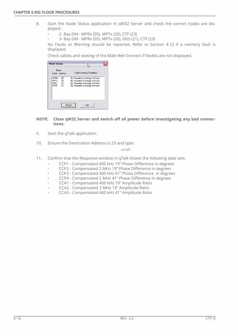
CHAPTER 6 RIG FLOOR PROCEDURES
8. Start the Node Status application in qW32 Server and check the correct nodes are dis-played:-• 2- Bay DM - MPRx (05), MPTx (20), CTF (23)• 3- Bay DM - MPRx (05), MPTx (20), DGS (21), CTF (23)No Faults or Warning should be reported. Refer to Section 4.12 if a memory fault isdisplayed. Check cables and seating of the Male Wet Connect if Nodes are not displayed.
NOTE: Close qW32 Server and switch off all power before investigating any bad connec-tions.
9. Start the qTalk application.
10. Ensure the Destination Address is 23 and type: rccd?
11. Confirm that the Response window in qTalk shows the following data sets:• CCP1 - Compensated 400 kHz 19” Phase Difference in degrees• CCP2 - Compensated 2 MHz 19” Phase Difference in degrees• CCP3 - Compensated 400 kHz 41” Phase Difference in degrees• CCP4 - Compensated 2 MHz 41” Phase Difference in degrees• CCA1 - Compensated 400 kHz 19” Amplitude Ratio• CCA2 - Compensated 2 MHz 19” Amplitude Ratio• CCA3 - Compensated 400 kHz 41” Amplitude Ratio
6-16 REV. 2.6 CTF_0

CHAPTER 6 RIG FLOOR PROCEDURES
• CCA4 - Compensated 2 MHz 41” Amplitude Ratio
12. Scroll to the right of the data set and confirm the gamma reading is non-zero.
6.5.8.2 Load Configuration
The configuration must be loaded to the entire system.
1. Start the qMWD Configuration utility if it is not already open.
CTF_0 REV. 2.6 6-17

CHAPTER 6 RIG FLOOR PROCEDURES
2. Select the correct configuration and click Open.
3. Select Store to... from the Load/Store menu.
4. Ensure all nodes are checked and click OK. When using a 2-Bay DM the Transmitter and Resistivity Downhole Nodes will be seen.When using a 3-Bay DM the Directional-Gamma Node will also be seen.
The configuration will be loaded to the SAI MPRx, DM MPTx (and DGS if using a 3-Bay DM)and the Centerfire. Check the confirmation messages.
6-18 REV. 2.6 CTF_0
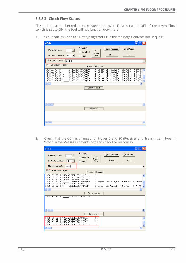
CHAPTER 6 RIG FLOOR PROCEDURES
6.5.8.3 Check Flow Status
The tool must be checked to make sure that Invert Flow is turned OFF. If the Invert Flowswitch is set to ON, the tool will not function downhole.
1. Set Capability Code to 11 by typing ‘ccod 11’ in the Message Contents box in qTalk:
2. Check that the CC has changed for Nodes 5 and 20 (Receiver and Transmitter). Type in‘ccod?’ in the Message contents box and check the response:-
CTF_0 REV. 2.6 6-19

CHAPTER 6 RIG FLOOR PROCEDURES
3. Type ‘invf: ‘Off’ in the Message contents box and click on ‘Send’.
4. To check the Flow status, type ‘invf?’ and click ‘Send’.
5. Check the Centerfire tool is working by typing ‘rccd?’ in the Message contents box. Nodes20 (Transmitter/ MPU) and 23 (Centerfire) will respond with non-zero Gamma values andResistivity values that match.
6-20 REV. 2.6 CTF_0

CHAPTER 6 RIG FLOOR PROCEDURES
6.5.8.4 Set System Time
1. Select Memory I/O utility from the qMWD folder.
2. Select Capability Code = 11 to access all menu features.
3. A screen warns the user that download speeds will be slow if the Receiver Comms. switchon the SAI is left on. The operator can turn off the Receiver Comms. switch if desired.
4. Check that all expected Nodes are displayed on the list on the left of the screen.
CTF_0 REV. 2.6 6-21

CHAPTER 6 RIG FLOOR PROCEDURES
5. Select the Set System Time option from the Commands menu.
6. Confirm the System Time displayed in the top left of the screen is the same as that set onthe PC.
6-22 REV. 2.6 CTF_0

CHAPTER 6 RIG FLOOR PROCEDURES
6.5.8.5 Set Up Recorder Files
1. Right click on the MPTx 20 Node and select Erase All to erase all the selected files withinthat node.
NOTE: The Erase option will result in the existing file remaining open but all data it con-tains being erased.
NOTE: The Close/ Delete options can be used to erase a file which will result in no newfiles being automatically opened.
2. Repeat the Erase All procedure for DGS 21 and PWR 23 Nodes.
NOTE: Node 21 is only seen when using a 3-Bay DM.
3. Confirm all files are open.
4. Close the Memory I/O Utility.
5. Turn the Tool Power switch in the OFF position.
6. Turn the Receiver Comm switch to the OFF position.
7. Turn the SAI Power switch to the OFF position.
8. Disconnect the Centerfire from the SAI.
CTF_0 REV. 2.6 6-23

CHAPTER 6 RIG FLOOR PROCEDURES
9. Inspect, and replace if necessary, the O-ring (411917) and 2 x Back-up Rings (411904) onthe Data Dump Cover.
10. Apply a light coating of DC-111 grease to the O-ring.
11. Apply Loctite 246 to the Data Dump Cover Bolts and insert the Cover.
12. Torque the Bolts to 15-25 lbf.ft (20-35 Nm).
The Centerfire assembly is now ready to be run into hole and Shallow Hole tested.
6-24 REV. 2.6 CTF_0

CHAPTER 6 RIG FLOOR PROCEDURES
6.5.9 Pre-Run/ Post-Run Calibration Check
Where possible the Centerfire tool should be tested before and after very run downhole witha view to confirming that the calibration factors that are loaded to the tool are effective andthe tool does not need a new Air Hang Calibration.
The test involves positioning the tool as far from any conductive material as possible andthen generating an average value for each data set based on 5 minutes of data. The test isrepeated after the run with the tool in exactly the same position. This will ideally produce anidentical set of values. Any major shift in any of the values can indicate a “shift” in the tool’scalibration that will require further investigation.
To generate the averaged data the Centerfire Realtime Diagnostics program is used. Theprogram can be downloaded from the Technical Support Portal at:
www.tensordt.com
The test can be completed with the tool in one of two positions both of which use the PODcable for communications to the SAI:
• The Centerfire Collar with no MWD string is suspended from a crane. The tool should ideally be slung and held horizontally and the POD cable should be hanging straight down from the tool. Ideally lifting straps which allow at least 20 ft/ 6.6m of vertical clearance between the crane hook and the collar should be used. Where possible the crane should hold the tool at least 25 ft./ 8.2 m off the ground and there should be no conductive material within 25 ft/ 8.2 m of the tool. Inability to ensure adequate clearance from conductive material will influence the results of the check. See the end of this section fro more information on test result analysis.
• The Centerfire tool is made up to the MWD string and the rest of the BHA. The entire system is then lifted up to a point where the Centerfire is as far from any conductive material (rigfloor, derrick structure).
NOTE: The pre-run and post-run tests must be performed in the same position to allowcomparison of the results.
Complete the following procedure to perform the test.
1. Connect the PWR Interface POD Cable (384339) to the Centerfire Tool.
2. Connect the POD Cable to the PWR POD Port on the Safe Area Interface [SAI] (RS-384356).Use of the SAI to POD Extension Cable (384335) may be necessary.
3. Connect the PC to the SAI using USB Cable (460003) or an RS 232 cable.
4. Turn the SAI Power switch to the ON position.
5. Turn the Receiver Comm switch to the ON position.
6. Turn the Tool Power switch in the ON position.
7. From the Programs menu on the PC select <qMWD> <Diagnostics> <qW32Server>.
CTF_0 REV. 2.6 6-25

CHAPTER 6 RIG FLOOR PROCEDURES
8. Start the Node Status application. Check that Nodes 05 (MPRx), 20 (MPTx), 21 (DGS) and 23(PWR) are displayed and that no Faults or Warning are reported. Refer to Section 4.12 if amemory fault is displayed.
NOTE: Nodes 20 and 21 will not be displayed if the MWD string is not connected to theCenterfire Collar.
NOTE: Node 21 will only be seen if a 3-bay DM is being used.Check cables if Nodes are not displayed.
9. Turn the Receiver Comm switch to the OFF position.
10. Open the Centerfire Realtime Diagnostics software.
11. Select Start New Run from the File menu.
6-26 REV. 2.6 CTF_0

CHAPTER 6 RIG FLOOR PROCEDURES
12. Check that the spread sheets that are displayed update with new data.
13. Select Run 5-Minute Average from the Calibration menu.
14. Select Start 5-Min Average. The program will control the tool to record data for 5 minutesafter which the average value for each of the eight compensated values will be displayed.
15. Open the Centerfire Realtime Diagnostics Program.
16. Select the Run 5 Minute Average option from the Calibration menu.
17. Start the 5 Minute Average test.
18. Maintain the tool in the same position until the test is complete.
19. When complete make a note of the results.Ideally the values will be very close to zero, indicating that the tool is in a non-conductiveenvironment and that the calibration coefficients are correct. Any significant variance fromzero either indicates that the tool was close to a conductive material or that the toolrequires a new Air Hang Calibration and should not be run if possible.
CTF_0 REV. 2.6 6-27

CHAPTER 6 RIG FLOOR PROCEDURES
20. Close the Centerfire Realtime Diagnostics Program.
21. Close the W32 Server.
22. Switch off all power on the SAI.
23. Remove the POD cable.
When comparing the results of the pre-run and post-run tests the user should consider anychanges to the environment (conductive material, EM interference) that may have affectedeither set of measurements. If the test was performed close to the ground then the absenceor presence of water will also have an effect.
To determine how much of a “shift” in values should be considered significant the user mustassess the “cleanness” of the test site. In an area in which there are considerable amounts ofconductive material close to the tool then more variance in the pre-run and post-run testswill be expected than in a relatively conductivity-free area.
Any considerable shifts in values should be reported to the end user of the data as it mayindicate a “shift” in the tool’s calibration. In this case a new Air Hang Calibration will berequired to be performed and then any logged data re-processed using the new Air Hangcoefficients. Contact the regional service centre for more information on re-processing datawith revised Air Hang coefficients.
6-28 REV. 2.6 CTF_0

CHAPTER 6 RIG FLOOR PROCEDURES
6.5.10 Shallow Hole Test
To confirm correct operation of the Centerfire system it should be tested before running theassembly to the bottom of the hole.
NOTE: Operation of the Centerfire tool will not be confirmed during a shallow hole test ifthe tool is in Delay Mode which is set in the Configuration.
Configure the qMWD PC for pulse detection by following the instructions the Tensor MWDOperations Manual (TMWD_O).
NOTE: High Temperature batteries may not allow a good rest to be performed if the mudtemperature is not high enough to heat the batteries.
NOTE: The Centerfire system will not return good data when in Recorder Delay Mode.
Before the Shallow Hole Test the operator must decide at what flow rate to perform the test.This will usually be far below the planned drilling flow rate. The test flow rate must be highenough to be recognised by the flow switch. The operator must determine the Stand PipePressure [SPP] at this flow rate and configure the Surface Receiver Controls in the MWDConfiguration utility to ensure the SAI allows the transmitted pulses to be detected anddecoded by the system.
NOTE: High Pulse Amplitude Limit [HiPL] and Low Pulse Amplitude Limit [LoPL] cannot bechanged in the Basic Receiver Control Settings within QMWDPC software when thesystem recognises flow. However, the values can be changed in qTalk as long asthe capability code is changed to 11 (Ccod 11).
1. Run the assembly into hole until the MWD string is below the mud line.
2. Bring on the pumps to a flow rate at which the tool will recognise flow.
3. After the Transmit Delay Time (seel Configuration) has ended the tool starts transmitting.
4. The operator should wait for a complete survey to be transmitted and enough Toolface/Logging data to ensure operation of the tool. When assessing the quality of the transmit-ted data consider the following:• Data derived from the Directional Module’s magnetometers (azimuth, azimuth of
toolface, total magnetic field) will all be affected by casing.• Gamma rays will be attenuated by any casing or large top hole section and so
gamma data may be low.• Resistivity data will be greatly affected by casing and the Centerfire may return error
messages in the Static Survey. Refer to Table 6-1 for information on possible ReSR errors seen during Shallow Test. Refer to Section 5.2.3 for further information on the Resistivity Status Register (ReSR).
5. Once the operator is sure all modules are performing as expected the pumps should beshut down and the tool run to bottom.
CTF_0 REV. 2.6 6-29

CHAPTER 6 RIG FLOOR PROCEDURES
Table 6-1 ReSR Errors at Shallow Test
Bit Error State Acceptable Comments
Yes No
0 Receiver 1 X Proximity of antennas to metallic casing can cause erroneous data acquisition which is flagged as out-with acceptable limits.In casing any combination of antennas may be in error resulting in error codes between 8001 and 803F1000 0000 0000 0001 = 80011000 0000 0011 1111 = 803F
1 Receiver 2 X
2 Transmitter 3 X
3 Transmitter 1 X
4 Transmitter 4 X
5 Transmitter 2 X
6 Battery <16 VDC X
7 Battery Current>0.6A X
8 DSP Voltage(s) out of specifica-tion
X
9 No data recorded during 2 measurement periods
X Check PRD memory file is open
10 <10 hours memory remaining X May be acceptable for very short run
11 Memory errors since last power on
X
12 Processor fault X
13 DSP failed to initialize X
6-30 REV. 2.6 CTF_0

CHAPTER
SOFTWARE SETUP
7.1 Introduction
The Centerfire system uses LogView II software to present logged data. The operator mustset up the software to ensure the correct data is displayed as the end user of the datarequires.
LogView II operation is covered by the LogView II Operator Manual (981021-04-01). Thissection will cover all Centerfire specific information that is not included in the LogView IImanual.
Use of the LogView II software requires a license and is HASP protected. Contact the regionalTensor DT base for details.
CTF_0 REV. 2.6 7-1

CHAPTER 7 SOFTWARE SETUP
7.2 Log Plot Data
The operator must enter Centerfire-specific information to ensure the correct presentationof the logged data.
7.2.1 Well Data
All standard information as described in the LogView II manual must be completed. Depthrelated data is important when logging.
7-2 REV. 2.6 CTF_0

CHAPTER 7 SOFTWARE SETUP
7.2.2 BHA Data
For every run the BHA data must be input. To create a new run use the option in the RunData tab.
7.2.3 Subs Data
Information on all gamma and resistivity tools at the rig site must be entered.
7.2.3.1 Gamma
Add a New Gamma Sub and enter its serial number. Select the Tool Type from the menu andenter the calibration date (which can be found on the tool paperwork). Leave the AmershamCorrection Factor as 1.
NOTE: The OD and ID of the collar must be input if a non-standard Gamma collar is beingused.
CTF_0 REV. 2.6 7-3
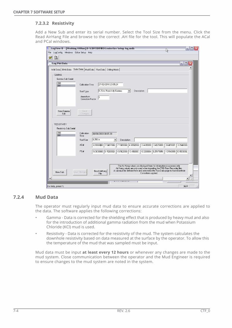
CHAPTER 7 SOFTWARE SETUP
7.2.3.2 Resistivity
Add a New Sub and enter its serial number. Select the Tool Size from the menu. Click theRead AirHang File and browse to the correct .AH file for the tool. This will populate the ACaland PCal windows.
7.2.4 Mud Data
The operator must regularly input mud data to ensure accurate corrections are applied tothe data. The software applies the following corrections:
• Gamma - Data is corrected for the shielding effect that is produced by heavy mud and also for the introduction of additional gamma radiation from the mud when Potassium Chloride (KCl) mud is used.
• Resistivity - Data is corrected for the resistivity of the mud. The system calculates the downhole resistivity based on data measured at the surface by the operator. To allow this the temperature of the mud that was sampled must be input.
Mud data must be input at least every 12 hours or whenever any changes are made to themud system. Close communication between the operator and the Mud Engineer is requiredto ensure changes to the mud system are noted in the system.
7-4 REV. 2.6 CTF_0

CHAPTER 7 SOFTWARE SETUP
Use of a conductivity meter can allow mud resistivity readings to be taken by the operator.
7.2.5 Run Data
The Operator must select the Gamma and Resistivity tools which are being used and alsoinput the sensor offsets from the bit for both tools. Refer to 5.6 for information on how tocalculate sensor offsets.
NOTE: When using LogView versions including and earlier than v3.32 the Hole Size valuemust be entered in INCHES regardless of the unit of length defined in the VariableUnits Editor .VUD file.LogView versions later than 3.32 require the Hole Size to be entered in unitsdefined by the VDU file.
CTF_0 REV. 2.6 7-5

CHAPTER 7 SOFTWARE SETUP
7.2.6 Drilling Mode
This is usually left as Centered or Pulling out of Hole depending on whether the rig is drillingor tripping.
7-6 REV. 2.6 CTF_0

CHAPTER 7 SOFTWARE SETUP
7.3 Data Sets
As data is processed within the Centerfire surface system various mnemonics are used todescribe the data sets.
7.3.1 Memory - Real Time
Memory data sets are identified with the suffix _RM where real time data sets have no suffix.
7.3.2 Gamma
Gamma data has four corrections applied all of which create a data set which can bedisplayed in LogView II.
• GRRaw = Gamma counts displayed in Counts Per Second
• GRCorr = GRRaw - Dark Current Factor. The Dark Current is a very weak current that flows through all photomultiplier tubes even when no incoming radiation is present.
• GAPIRaw = (GRCorr * Amersham Correction Factor) / (Tool CPS/ API). The Amersham Correction Factor is usually set as 1 in the tool run set up. The (Tool CPS/API) figure is determined by the collar size in which the Gamma tool is being run.
• GAPIMR = GAPIRaw - Background. The Background figure refers to the background radioactivity added to the measurement by radioactive mud in the hole. It is a function of hole size and KCl concentration.
• GAPICorr = GAPIMR x Borehole Correction Factor. The Borehole Correction Factor refers to the shielding effect produced by the mud in the hole. It is a function of the mud weight and the hole size.
The data sets which are usually plotted on logs are GAPICorr for real time data andGAPICorr_RM for memory data.
7.3.3 Resistivity
LogView II can present any of the 8 x Compensated Resistivity data sets. Data is processedeither from the raw R and X measurements stored in the PRD file or the Phase Difference andAttenuation data stored in the PCD file.
NOTE: The data in the and PCD & PRD files has not had the resistivity transform applieduntil it is imported into LogView.
LogView allows the presentation of either uncorrected or borehole corrected resistivity datasets. Corrected data account for mud resistivity and the difference between tool size andhole size.
CTF_0 REV. 2.6 7-7

CHAPTER 7 SOFTWARE SETUP
Table 7-1 LogView II Resistivity Data Sets
7.3.4 Conductivity
LogView II automatically computes conductivity for every resistivity data set. These data setsare indicated by the suffix _cond. For example, R19AHFcorr_RM_Cond is borehole correctedconductivity data calculated using the shallow, high frequency attenuation data.
NOTE: Conductivity is usually presented on a linear scale.
qMWD/ qTalka
a. Raw Phase Difference or Attenuation data sets before they have had the Resistivity Transform applied
LogView Database
LogView Realtime
LogView Memory
Measurement
CCP1 Re1p R19PLF R19PLF_RM 400 kHz 19” Phase Difference
CCP2 Re2p R19PHF R19PHF_RM 2 MHz 19” Phase Difference
CCP3 Re3p R41PLF R41PLF_RM 400 kHz 41” Phase Difference
CCP4 Re4p R41PHF R41PHF_RM 2 MHz 41” Phase Difference
CCA1 Re1a R19ALF R19ALF_RM 400 kHz 19” Attenuation
CCA2 Re2a R19AHF R19AHF_RM 2 MHz 19” Attenuation
CCA3 Re3a R41ALF R41ALF_RM 400 kHz 41” Attenuation
CCA4 Re4a R41AHF R41AHF_RM 2MHz 41” Attenuation
7-8 REV. 2.6 CTF_0

CHAPTER
LOGGING
8.1 Introduction
The procedures described in this section will enable the LWD operator to provide a highquality service with the Centerfire resistivity tool. In order to maintain the quality of theproduct (the log), the four areas of concern are:
• Depth Tracking accuracy
• Data continuity
• Data validity
• Data presentation
8.1.1 Logging through Casing
Logging a section of the well AFTER it has been cased is possible with the Gamma Ray toolbut NOT with the Resistivity tool. The LWD operator should note that there will beattenuation of the Gamma signal which will be dependant on the casing size and the amountof cement behind the casing. This should be recognized when trying to correlate the logproduced through casing with open-hole offset logs.
As with normal logging, communication with the driller for accurate depths is vital. If aprevious section of hole has been logged through the casing, ensure an overlap exists withthe previously logged section.
The customer may require certain sections of a hole to be re-logged. This may be to verifythe operation of two different sensors on consecutive runs (like the Benchmark Surveys dofor the Directional tool) or to verify the tool response through a zone of interest.
Accurate depth measurement is vital for a good log to be produced and the MWD operatormust communicate with the driller to make sure the MWD depth matches the driller’s depth.
8.1.2 Casing Shoes
The LWD operator must be aware of the depth of the last casing shoe as proximity to casingcan affect the Survey accuracy and information from logging sensors. Again, goodcommunication with the drill crew is necessary.
NOTE: A casing shoe is likely to have areas of rough metal exposed (from drilling theshoe-track) and this can damage LWD tools. It is always beneficial to the LWDoperation if the shoe is drilled without the LWD tool in the BHA; this means thatthe shoe may be passed several times and rough metal removed before an LWDtool is used. Oil company policy will dictate if this happens.
CTF_0 REV. 2.6 8-1

CHAPTER 8 LOGGING
8.2 Normal Logging
Reference should be made to the MWD Operator Manual and the Surface System OperatorManual.
8.2.1 Depth Tracking
Procedures for normal logging are:
1. Make sure all calibration inputs are correct.
2. Check with the driller for the start depth.
3. Set the software to the required start depth.
4. When pumping commences, it is good practice to have the driller pump up the surveyBEFORE starting to drill. In this way, the LWD operator has time to check that the tool is inthe correct mode and also no logging data is lost while the survey is transmitted. The latterpoint is especially important when drilling is fast.
5. Obtain pipe figures from the drill floor; this will enable the LWD operator to keep up todate with the pipe tally.
6. After every pipe connection, the LWD operator MUST make sure that the depth on the sur-face system matches that of the driller/ pipe tally. If there is a difference, the operatormust decide how to fix it.
8.3 Logging Data Continuity
NOTE: Prior to any Logging operations, the LWD operator should ascertain the custom-ers' requirements for log format.
There should be no gaps in the data being transmitted. If, for any reason, data is notcontinuous, the operator MUST take steps to rectify this. Gaps may be due to:
• Downhole tool problems
• Pulse Detection problems
• Surface Sensor problems (SPP OR Rotary OR cables/ connectors)
• Computer system problems
8-2 REV. 2.6 CTF_0

CHAPTER 8 LOGGING
8.4 Logging Data Validity
The data (Gamma & Resistivity) received at the surface should be assessed to determine ifthe values are correct for the formation being drilled. An offset log is very useful for thispurpose. If an offset log is not available (for example in an exploration well), sampleinformation from Mud Loggers will help.
Problems with data validity may be due to:
• Downhole tool problems
• Pulse detection
• Incorrect calibration/ correction factors being applied at surface
When comparing the Centerfire log with an offset log the operator must be aware howdifferent types of resistivity measurement can result in different log responses.
NOTE: Data that is out with the operational range for that measurement (see Table 2-1)should not be compared with other data sets. It is common for data recorded outwith the operating range of the measurement to behave differently to thatrecorded within the operating range.
8.5 Logging Data Presentation
Data presentation is also very important; it is the operator’s responsibility to ensure that thelog header information is kept up-to-date and the data is presented in a way that makes iteasy for the Geologist to read the log. Points to look for are:
• Correct scales (depth & data) applied to logs
• Survey information must match the Directional Driller's data
• Header and footer information must be complete and up-to-date
• Comments section filled in with any pertinent information
• Repeat sections identified (annotated on log or header comments)
8.6 Notes on the Log Header Information
The log header contains all the vital information about the well, the drilling conditions andabout the MWD/ LWD tool(s). It is important to keep this information accurate and up-to-dateas geologists and petrophysicists will rely on it when interpreting the log.
It is particularly important to record the following parameters:
• Mud temperature
• Mud resistivity and temperature of measurement
• Mud filtrate resistivity and temperature of measurement
See Section 7.2.4 for more information on mud resistivity measurements.
CTF_0 REV. 2.6 8-3

CHAPTER 8 LOGGING
8.6.1 Conductivity Meter Conversions
Conductivity meters normally display readings in mS.cm (milliSiemen.centimetres) OR μS.cm(microSiemen.centimetres). To convert readings of Conductivity in the above units toreadings of Resistivity, do the following:
• Resistivity (1 ohm.m) = 10/(meter reading in mS.cm)
• Resistivity (1 ohm.m) = 10000/(meter reading in μS.cm)
8.7 Repeat Sections
Customers can request repeat sections of log; this may be to confirm a tool's response or tomake sure that different tools are responding in the same manner.
Repeat sections may be done during the same run, for instance during a wiper (short) trip,OR may be obtained while tripping into or out of the hole.
Depth Tracking, Data continuity, validity & presentation are of equal importance in relogsections as they are during normal drilling however the Rate of Penetration from repeatsections is unlikely to be used in final plots.
NOTE: The invasion of mud into the formation is a major control on the resistivity meas-ured by the Centerfire tool and the operator must be aware of how it will affectthe log of a repeat section.
8.7.1 Relogging
The following steps may be required if a section is to relogged.
• Determine the interval to be logged (normally from Geologist). Determine the bit depths that relate to the top and bottom of the re-logged section based on sensor offsets (see Section 5.6).
• Inform the customer/ drill crew of time required for operation.
• Prepare the Depth Tracking System. The system may need to be re-calibrated if any drill line has been slipped and cut.
• Communicate with Drill Floor on procedure to be followed, emphasising the need for speed control.
• Start Depth Tracking
• Monitor trip speed to ensure a data density of 1 point per 0.5ft/ 15cm or better (see Section 8.7.2).
• Monitor tool performance
• Stop Depth Tracking
• Check that log is satisfactory; process data as quickly as possible
• Inform Drill Floor to carry on normally with trip
8-4 REV. 2.6 CTF_0

CHAPTER 8 LOGGING
8.7.2 Logging Speed
Usually a data density of 2 points per foot (1 point every 30cm) is required but the operatorshould discuss actual requirements with all parties. The maximum trip speed should then becalculated to allow for the required data density.
The calculation of logging speed can be summarised:
where:
DD = Data Density (points per depth unit)
TR = Trip Rate (depth units per hour)
UR = Update Rate (seconds)
8.7.2.1 Real Time Relogging
When real time data is required during a relogging section the operator should consider theaverage transmission time of the logging data. Update rate is controlled by Pulse Width andthe Toolface/ Logging sequence definition. For more information on the calculation of realtime update rates refer to the Tensor MWD Operations Manual (981021-100-11) Section 5.5.
It should be noted that the tripping process may need to wait for the static survey to betransmitted after every connection to ensure the tool is transmitting logging data when it isbeing tripped over the zone of interest.
The assembly should be rotated during tripping if the Dynamic T/L Sequence Change featurehas been enabled in the DM configuration as this will stop the transmission of toolfaces thusmaximising the amount of logging data that is transmitted.
8.7.2.2 Memory Logging
The update time of the logged data is controlled by the Dead Time for MWD Mode that is setin the PWR Processing Controls when programming the system (see Section 5.3.14). A 1second Dead Time will result in a 10 second update rate for the resistivity and gamma datastored in the PRD and PCD memory files. Therefore, a trip rate of 180 ft/hr would achieve adata density of 2 points per foot when using a 1 second Dead Time.
DD 3600TR UR¥---------------------=
CTF_0 REV. 2.6 8-5

CHAPTER 8 LOGGING
THIS PAGE INTENTIONALLY LEFT BLANK
8-6 REV. 2.6 CTF_0

CHAPTER
PULLING OUT
9.1 Preparing for Tool Change
• Determine what is to be changed (Batteries, whole tool)
• Inform Customer/ Drill Floor of requirements and procedure
• Gather all Tool Handling equipment, special tools, hand tools
• Prepare new tool - Centerfire tests, MWD tool tests, offset calculations.
9.2 Pulling Out of the Hole
9.2.1 General Considerations• Tool change?
• Batteries?• Pulser due for change?• Tool problem? A complete tool change is strongly recommended.• Is the back-up system ready to go?
• No tool change - tool racked back?• How long in the derrick?• Does the Directional tool have to be laid down for lengthy rig down-time (refer to
Section 9.3)• Flush out the top of the Centerfire collar/ wet connect area with water?
• During the trip out:-• Collect all equipment that will be required on the rig floor for tool handling and
memory download• Determine logs required by the customer• Check all surface systems - sensors and cables• Collect as much information as possible for the next run
9.2.2 Downloading the Centerfire Memory
The Centerfire memory can be downloaded on the drill floor; due to the possible dangersassociated with the exposure of live electrical connections on the rig floor (shock, spark, firehazard), a Hot Work Permit must be obtained before carrying out any work. Consider thefollowing:
CTF_0 REV. 2.6 9-1

CHAPTER 9 PULLING OUT
• Have all hand tools and surface equipment ready to minimise rig downtime required to download the data.
• Clearly communicate all instructions to the rig crew before beginning any operation on the drill floor.
• Take extra care when working over the well.
• Follow procedures outlined in section 4.12 to download the memory files.
NOTE: Download both the PRD file (raw R & X data) from the Centerfire - Node 23 - andthe PCD file (compensated PD & AT data and Directional Module diagnostics) fromthe DM - 2-Bay Node 20, 3-Bay Node 21.
• Verify the quality of all data before concluding the operation and disconnecting from the tool.
9.2.3 Log Copies
Once the Centerfire tool‘s memory has been downloaded the data should be processed sothat a memory log can be presented to the customer.
9.2.4 Post-Run Calibration Check
The tool should be tested to confirm the calibration coefficients that have been applied tothe data are still valid. Refer to Section 6.5.9 for information on how to perform the test andassess the results.
9-2 REV. 2.6 CTF_0

CHAPTER 9 PULLING OUT
9.3 Racking-back
9.3.1 Introduction
There will be times during the course of a job when the client or drilling contractor willrequire the tool to be racked-back in the derrick while other rig operations continue. Thismay cause no problems at all but in other situations the operator should make every effortto remove the MWD tool string before the drill collar is placed in the derrick. The reason forthis is that the drilling fluid MAY dry out in the Pulser and cause the Poppet Valve to stick. Thefollowing points are guidelines only and actual procedures will vary according to locationsand conditions:-
9.3.1.1 When to rack the tool back
RACK BACK if the tool is to be in the derrick for a short time only (a rough guide is <6 hours)
RACK BACK if the drilling fluid in use is oil-based
RACK BACK if the drilling fluid in use is water with a VERY LOW solids content
9.3.1.2 When to lay the tool down
LAY DOWN when the tool is to be in the derrick for a long time (a rough guide is >6 hours)
LAY DOWN when the drilling fluid is water-based, has a high solids content and climaticconditions are hot or very cold and dry (extremes of climate can cause a water-base mud todry up very quickly).
CTF_0 REV. 2.6 9-3

CHAPTER 9 PULLING OUT
9.4 Laying Down the Centerfire
This procedure details the laying down of the Centerfire tool.
In most cases the 4.75”/ 6.91” Centerfire collar and Gamma sub will be laid down andtransported back to base together. It may be desirable to break the torque from thisconnection before laying down the assembly.
9.4.1 Laying Down the MWD Tool
The procedure for laying out a Tensor MWD tool is the reverse of the pick-up processdescribed in Section 6.5. However, consider the following:-
Walk out the Drill Collar connections; spinning out may damage the threads.
Wipe the tool down with rags as it comes out of the drill collar.
BE AWARE that if the pressure housings are very difficult to separate, this may indicate aproblem with the battery module. There will be considerable internal pressure if there is aruptured cell and this may force the pressure housings apart, thus making separationdifficult.
Have the next tool (if required) prepared, tested and on the rig floor ready to assemble.
WASH OUT the inside of Female Wet Connect IMMEDIATELY after removing the MWD tool; donot allow mud to dry out inside the Wet Connect.
Try to flush as much mud as possible from the central bore and outer diameter of the collar.
9.5 Equipment Levels
It is part of the LWD operator's job to continually evaluate equipment levels and futurerequirements at the rigsite.
Refer to the Sections 11.2 - 11.4 for lists of rigsite equipment required to run the Centerfiretool.
9.6 Battery Calculations
The operator must record the battery usage after the run and calculate remaining batterylife.
Refer to 4.3.1 for information on Battery usage calculations.
9-4 REV. 2.6 CTF_0

CHAPTER 9 PULLING OUT
9.7 Conclusion of Operations
At the end of LWD operations the operator must organise the following:
• Field copies of logs and surveys
• Rig down, leaving the site as it was when the equipment arrived on-site
• Pack all tools and surface equipment securely for the journey back to base
• Prepare shipping documents if required
• Prepare Job Ticket if required
CTF_0 REV. 2.6 9-5

CHAPTER 9 PULLING OUT
THIS PAGE INTENTIONALLY LEFT BLANK
9-6 REV. 2.6 CTF_0

CHAPTER
TROUBLESHOOTING
10.1 Introduction
The following information provides a guide to the operator to aid problem solving at the rigsite. Onegolden rule of problem solving should be remembered - WHERE APPROPRIATE, TEST THE TESTEQUIPMENT TO MAKE SURE IT IS WORKING BEFORE STARTING ANY FAULT FINDING.
The information presented is specific to the Centerfire Resistivity and Gamma Ray LWD system, bothdownhole and at the surface.
Problem Possible Cause(s) Things to Consider/ Course of Action
RESISTIVITY
Resistivity log anomalies - comparison with offset logs or comparison between Cen-terfire data sets
Corrections not applied prop-erly
Check the mud details entered in soft-ware regularly/ whenever a change and that the Rm and Rmf are meas-ured and recordedCheck that the calibration of the Con-ductivity Meter is correct and up-to-date Verify the Mud Engineer is provid-ing accurate information
Log type Compare logging toolslogging principlefrequency(s)spacing
Time When was the comparison log run?
Environment InvasionHole Angle and:-
Shoulder bed effectsEccentricityAnisotropyMud type and properties
Calibration Check that the correct .AH (air hang) file is in use (memory data only)Change tool if calibration suspect
CTF_0 REV. 2.6 10-1

CHAPTER 10 TROUBLESHOOTING
Operating Range Check the measurement is not out with its operating range. For example, 19” 400 kHz AT should only be deemed accurate between 0.1-10 ohm.m
No resistivity data Tool failedBattery failureWet connect failedCenterfire electronics failedTool in Delay Mode
Monitor ReSR (if possible) and ReNF, change the tool at the next opportu-nityCheck for other data - surveys, tool face
Resistivity Data, but with errors
Electronics failureCoil failureCalibration errorsNearby casing or fishPulse detection problems
Monitor ReSR and ReNFReal-time editing and fix pulse detec-tion problemsCheck well plan or anti-collision plotChange the tool
Resistivity log offscale - high Hydrocarbon bearing formationEvaporite formationCalibration errorsTool errorPulse detection problemsMeasurement Type (attenuation has smaller range of measure-ment)
Check formation with wellsite geolo-gist/ mud loggersCheck offset logs for comparisonChange tool to compare response if calibration or tool is suspect
GAMMA
Gamma Ray log anomalies - comparison with offset logs
Corrections are wrong or not applied in software
Check that the OD and ID of the Gamma sub is correct in the softwareCheck that the borehole size records are correctCheck that the Amersham Correction Factor has been entered correctlyCheck that the mud details have been entered correctly in the software
Spectral gamma tool used in offset wellAzimuthal gamma tool used in offset wellDifferent drilling fluid
Check the tool typeBe aware of the possible differences in responsePotassium contentWeighting
No gamma data Tool failedWet connect failedCenterfire electronics failed
Change the tool at the next opportu-nity
Gamma Data, but with errors electronics failuredetector failurecalibration errorsPulse Detection problems
change the tool
real-time editing and resolve detection problems
Gamma log offscale - high Hot shaleTool errorPulse detection problems
Check formation with wellsite geolo-gist/ mud loggersCheck offset logs for comparisonChange tool if equipment problem
Problem Possible Cause(s) Things to Consider/ Course of Action
10-2 REV. 2.6 CTF_0

CHAPTER 10 TROUBLESHOOTING
The Centerfire Troubleshooting Guide includes a decision tree to be used when investigating rigsitesystem problems. The Guide can be downloaded from the Tensor DT website at www.Tensordt.com.
Gamma Ray log anomalies - comparison with offset logs
Different drilling fluid Potassium contentWeighting
DEPTH TRACKING
Depth anomalies Depth system calibration Check calibration
Depth tracking sensors Check function
TVD mismatch between logs Check all surveys and survey calcula-tions are correct - compare with Direc-tional DrillerCheck that the Depth Datum elevation is correctCheck that logs are using TVD or TVDSS
Sensor offset error Check sensor offsets entered in the software
Pipe tally errors Manually check pipe tally
Incorrect Depth Tracking Varia-ble settings
Check settings for In-Slips Threshold, String Weight Threshold, Off Bottom Travel Distance, In-Slips Travel Dis-tance and Minimum Weight on Bit
Problem Possible Cause(s) Things to Consider/ Course of Action
CTF_0 REV. 2.6 10-3

CHAPTER 10 TROUBLESHOOTING
THIS PAGE INTENTIONALLY LEFT BLANK
10-4 REV. 2.6 CTF_0

CHAPTER
PARTS LISTS
11.1 Introduction
This section details all the parts and tools required for field operation of the Centerfire System.
NOTE: Parts lists are correct at time of writing but are subject to change therefore please contactTechnical Services or the Customer Service Representative when ordering parts to ensure thecorrect part numbers are used.
CTF_0 REV. 2.6 11-1

CHAPTER 11 PARTS LISTS
11.2 Downhole Equipment
11.2.1 MWD/LWD Downhole Equipment 175ºC, Centerfire (RS-411389)
11.2.2 Battery Cartridges
11.2.3 4.75” Centerfire Assembly
11.2.4 6.91” Centerfire Assembly
11.2.5 8.25” Centerfire Assembly
PART # DESCRIPTION QUANTITY
981390 PULSER ASSEMBLY WITH WET CONNECT, 175ºC 2
981524 CONNECTOR, JUMPER 2
981675 HOUSING BATTERY 6
981755 BOWSPRING CENTRALIZER 12
981750 FINNED SLEEVE 10
981925 RETRIEVAL NECK/ SPEARPOINT KIT 4
RS-411387 DIRECTIVE ELEX PKG 2 BAY DM, 175ºC 2
PART # DESCRIPTION QUANTITY
981656 BATTERY PACK LITHIUM 150ºC 1
981657 BATTERY PACK LITHIUM 180ºC 1
PART # DESCRIPTION QUANTITY
RS-994000 4 3/4” COLLAR ASSEMBLY, 6 POCKET CENTERFIRE 1
988030 GAMMA MODULE ASSEMBLY, 175ºC, CENTERFIRE 1
971943 GAMMA COLLAR 4.75 PWR 1
PART # DESCRIPTION QUANTITY
RS-996000 6.91 COLLAR ASSEMBLY, 6 POCKET CENTERFIRE 1
988030 GAMMA MODULE ASSEMBLY, 175ºC, CENTERFIRE 1
971925 GAMMA COLLAR 6.75 PWR 1
PART # DESCRIPTION QUANTITY
RS-998000 8 1/4” COLLAR ASSEMBLY, 6 POCKET CENTERFIRE 1
11-2 REV. 2.6 CTF_0

CHAPTER 11 PARTS LISTS
11.3 Surface Equipment
11.3.1 Surface System Support Kit, Centerfire (460006G002)
11.3.2 KIT, MWD Depth Tracking Option (985006G006)
PART # DESCRIPTION QUANTITY
384008 CABLE, SUPPLY BOX TO PC QBUS 1
384025 CABLE, SUPPLY BOX TO SURF PROGRAM 2
384335 CABLE, POD EXTENSION 1
384339 POD CENTERFIRE INTERFACE 2
384347 CABLE ASSEMBLY, SAI TO PRESSURE TRANSDUCER UNION 1
RS-384356 SAFE AREA INTERFACE, 3 BAY 2
450017 PRESSURE TRANSDUCER 2
450025 CABLE DB9F TO DB9M, 10 FT, QNIC 2
460002 CABLE ETHERNET, RJ-45 CONNECTORS, 25 FT 1
460003 CABLE USB A-B 2
971977 CABLE KIT, FOREIGN POWER 1
981996 NUT, WING 1
981997 SUB 2”, FEMALE 1
981998 SEAL, RING 1
983130 CABLE, PROGRAMMING TOP 1
PART # DESCRIPTION QUANTITY
001359 CABLE ASSEMBLY, SAI TO JUNCTION BOX 2
350020 DRAWWORKS DEPTH ENCODER KIT 1
380116 PAPER FANFOLD PRINTREX 6
380117 CHART PRINTER PRINTREX 2
384036 CABLE, SENSOR TO JUNCTION BOX 6
450014 JUNCTION BOX ASSEMBLY 2
450019 CABLE ASSEMBLY, CROSSOVER TO 6 PIN TRANSDUCER 2
450109 TRANSDUCER, LINE TENSION 2
971977 CABLE KIT FOREIGN POWER 1
CTF_0 REV. 2.6 11-3

CHAPTER 11 PARTS LISTS
11.3.3 Retrieval Equipment Kit (460008G001)
11.3.4 Hand Tool Kit (460009G001)
PART # DESCRIPTION QUANTITY
351180 LIFTING SLING 2
971172 BAR, SPACER BRASS, 5 FT 2
971194 BAR, SPACER ALUMINUM, 5 FT 3
981218 TOOL, J-UNLATCH 2
981701 RETRIEVAL OVERSHOT 2
981734 SPANG JAR 2
981818 BOWSPRING CENTRALIZER 2
981819 CLEVIS WITH PIN 2
981921 HEAD ASSEMBLY, WIRELINE 0.092” 2
PART # DESCRIPTION QUANTITY
060101 ALUMINUM JACK STAND 12
981254 DC 111 SILICONE GREASE 2
981923 WRENCH MULESHOE ALIGNMENT 2
981924 TOOL, INTERCONNECT ALIGNMENT 2
981941 WRENCH, SPANNER, 2” X 6” 4
983140 MODULE BREAKOUT UNIT 1
983150 MODULE INTERCONNECT CABLE 2
983230 WRENCH, FRICTION GEAR, 1 7/8” 2
983231 WRENCH, FRICTION GEAR, 1 3/4” 1
985011 SAND CONTENT KIT 1
985018 DIGITAL MULTIMETER 1
11-4 REV. 2.6 CTF_0

CHAPTER 11 PARTS LISTS
11.4 Spares and Consumables
11.4.1 Spare Parts
11.4.2 Consumables
PART # DESCRIPTION QUANTITY
104110 SCREW - PULSER SCREEN 20
422340 O-RING 011 - BATTERY MODULE SAFETY PLUG 20
422900/ 422502a
a. Arctic O-ring numbers listed second.
O-RING 220 - INTERCONNECT, MODULE THREAD PROTECTOR 20
411947/ 422519 O-RING 326 - MALE WET CONNECT 20
971821 THREAD PROTECTOR GAMMA MODULE 1
971915 BACK UP RING 326 - MALE WET CONNECT 10
971916 WIPER SEAL - MALE WET CONNECT 20
422400 WET CONNECT CONDUCTOR SPRING 1O
422992 O-RING 221 - PULSER HELIX END 20
981140 POPPET TIP 1.122” 3
981213 POPPET TIP 1.086” 3
981214 POPPET TIP 1.040” 3
981477 SCREEN PULSER 5
422342 O-RING 027 - INTERCONNECT SPLIT RINGS 20
422345 O-RING 213 - INTERCONNECT 20
422994 O-RING 016 - BATTERY SAFETY PLUG 20
981645 BATTERY SAFETY PLUG 3
981845 MODULE THREAD PROTECTOR 3
PART # DESCRIPTION QUANTITY
380116 PRINTER PAPER 6
400199 LOCTITE 246 MED STRENGTH 1
981254 SILICONE GREASE CARTRIDGE 2
CTF_0 REV. 2.6 11-5

CHAPTER 11 PARTS LISTS
THIS PAGE INTENTIONALLY LEFT BLANK
11-6 REV. 2.6 CTF_0

CHAPTER
APPENDIX
12.1 General Battery Handling and Safety
NOTE: If you are dealing with a known overheated or damaged battery assembly, protec-tive clothing (overalls, safety boots, safety glasses, rubber gloves and apron, respi-rator and mask) must be worn. If you are dealing with a battery assembly and itbecomes clear that the assembly has been overheated or damaged, STOP and puton protective clothing, rubber gloves and a respirator. If the battery cells areinvolved in a fire, do not use water to put out the flames. The fire should be extin-guished with a Lith-X (Graphite Class D fire extinguishing agent) powder. SodiumCarbonate should be spread over all exposed parts that are not burning.
12.1.1 Introduction
The Battery Module of the Tensor system utilises industry standard, high energy, long lifeLithium batteries. The voltage of these batteries is not comparable to that of manganese oralkaline batteries. Therefore, never mix batteries of different types, model or chemistry in abattery pack.
Batteries have a shelf-life of greater than ten years if stored at the manufacturersrecommended temperature of 0 - 25ºC and in a dry, well-ventilated area. Batteries should beprotected against excessive humidity if prolonged storage is anticipated.
The battery storage area in a workshop or warehouse should be secure, clearly marked asBattery Storage and be provided with the correct class of fire extinguisher.
“Passivation” of cells occurs during any period of storage or non-use. An oxide layer buildsup on the Lithium cathode. This has the advantage of minimising the degradation of thecells’ performance over time but this passivation layer must be broken down by appropriateloading before a battery assembly is ready for field use.
Individual cells may swell slightly in use depending on the load applied and the maximumtemperature to which they are exposed.
12.1.2 Battery Composition
The batteries contain a Lithium (or, in the case of higher temperature rated cells, a Lithiumalloy) cathode immersed in a Thionyl Chloride electrolyte. Lithium is a metallic element thatreacts violently with water, releasing hydrogen gas. Thionyl Chloride is a toxic organic liquidwhich, in the presence of water or water vapour, decomposes into the toxic gases sulphurdioxide and hydrogen chloride.
CTF_0 REV. 2.6 12-1

CHAPTER 12 APPENDIX
The individual cells are constructed so as to withstand internal pressures generated duringoperation and it is important to remember that the cell contents are highly pressurised atelevated temperatures.
NOTE: If the batteries should become damaged or ruptured, sulphur dioxide, hydrogenchloride and hydrogen will be released. Should the battery be ruptured to theextent that the internals are exposed to the atmosphere, Lithium and ThionylChloride saturated carbon would be present in addition to the above.
12.1.3 Workshop Practices
When the battery cartridges are no longer useable, they should have a normal load appliedto them to deplete them prior to being stored for disposal. A battery is depleted when itreaches 0 V DC under LOAD conditions. Under NO LOAD conditions, the open circuit voltageshould stabilise at less than 0.5 V DC after one hour. If the voltage recovers, the load shouldbe re-applied for 24 hours or until such time as the voltage does not recover to more than0.5 V.
It must be remembered that the batteries are never 100% depleted and should still behandled with care in all subsequent operations.
12.1.4 Overheating or self-heating:
A battery cell will rupture or explode if the lithium within it reaches its melting point. Asubstantial safety margin is essential in order to allow for internal self-heating in normaloperation, the possible occurrence of hot-spots and unexpected changes on operationalconditions. For these reasons, the maximum operational temperature limit for standard cellsis 150ºC (302ºF) and for High Temperature cells is 180ºC (356ºF).
As soon as a hot cell is detected, all personnel should be evacuated from the area. Thetemperature of the cell should be monitored with a remote sensing device such as aninfrared temperature probe. The area should remain evacuated until the cell has cooled toroom temperature. When the cell has returned to room temperature, it can be handled by anoperator wearing protective equipment (face shield, flak jacket, respirator and gloves) withnon-conductive pliers or tongs and placed in plastic bags containing sodium carbonate andplaced in labelled drums containing Vermiculite or other non-flammable cushioning materialsuch as sand or sodium carbonate to cushion the cells. These materials should be disposedof as per local hazardous waste disposal regulations.
12.1.5 Damaged Power Sections:
If the Battery Module has been ruptured or flooded whilst down-hole, it is probable that oneor more individual cells is also damaged. IF SAFE TO DO SO remove the damaged batterypack to a remote area, but NOT is direct sunlight, and allow any chemical reactions to runtheir course. Post warnings so that all personnel are alerted to the danger. It may benecessary to leave the battery pack for several days until all reactions are complete and thebattery has cooled down.
NOTE: Lithium batteries are not re-chargeable and it is hazardous to apply a reverse voltage to them.
NOTE: A violent chemical reaction takes place if Thionyl Chloride comes into contact with molten Lithium metal.
NOTE: Always wear gloves when handling batteries, especially when tools come out of the hole.
12-2 REV. 2.6 CTF_0
CHAPTER 12 APPENDIX
NEVER ATTEMPT TO OPEN OR DISASSEMBLE A CELL OR USE UNDUE MECHANICAL FORCEWHEN DEALING WITH THE BATTERY CELLS OR CARTRIDGES.
The following procedures should be adopted when dealing with damaged or overheatedbattery cartridges:-
1. Work outdoors.
2. Keep all non-essential personnel away from the assembly. Post warning signs around thebattery.
3. Have correct fire fighting materials to hand (Sodium Carbonate and Lith-X Graphite pow-der for extinguishing Class D fires).
4. Wear protective clothing: coveralls or laboratory apron, rubber gloves, rubber boots, respi-rator and face shield (preferable to goggles which leave parts of the face unprotected).
5. Leave the damaged assembly until the chemical reaction is complete and the assembly hascooled.
6. ONLY IF SAFE TO DO SO, disassemble the battery. When the damaged cartridge(s) hasbeen isolated, dispose of in the correct manner.
The risk of explosion or harm from a damaged battery assembly will be minimised, if theseprocedures are followed.
12.1.6 Battery Storage
Due to the chemical composition of the batteries, there are precautions that must beadhered to when storing the battery cartridges:
New/ Re-useable cartridges: cartridges should be stored in a cool (10-25ºC), dry,weatherproof facility. Storage of the cells at temperatures above 32°C (90°F) could adverselyaffect the life of the cartridges. Do not store in direct sunlight.
The cartridges should remain in their protective covering until they are ready for use. Thiswill protect the batteries from possibly becoming part of a short circuit.
Used (depleted) Cartridges: these cartridges should be discharged under normal loadconditions until the battery has reached 0 V on LOAD. The cartridge is then ready for disposalin the correct manner.
Used battery cartridges should be stored in a lockable steel container, filled with vermiculite,located away from main traffic areas. The container should be waterproof and be kept cooland dry. It should be labelled as containing battery cartridges or hazardous materials. Do notstore in direct sunlight. Use protective tape on the ends and wire-way to prevent accidentalshorts. Damaged or ruptured cells can be stored with other used batteries provided theyhave been properly isolated.
12.1.7 Battery Shipping and Disposal
Lithium batteries are classed as Hazardous Goods and are subject to special proceduresregarding their shipping and disposal. The rules and regulations for each country are
CTF_0 REV. 2.6 12-3

CHAPTER 12 APPENDIX
different and it is the responsibility of the user to see that laws and regulations are fullycomplied with.
The customers freight and shipping department should be aware of all IATA and DOTDangerous Goods Regulations that may apply (see NOTE) regarding the shipping of lithiumbatteries
NOTE: Lithium batteries must be disposed of through an authorised company that spe-cialises in the disposal of hazardous waste.
12.2 Safe Handling of Equipment Damaged by Battery Pack Venting
Lithium battery packs, properly used, are a safe and efficient power source designed tooperate under today's drilling conditions. However, due to the unpredictable nature of thedrilling operation, from time to time they are exposed to conditions beyond their safeoperating limits and this can result in battery venting or even an explosion.
When such an incident happens the first priority is the safety of personnel. Lower on thescale of priorities, but still important, is the recovery of the equipment. This document givesguidance on procedures for safe handling of equipment so affected, what is worth returningand what is not.
Please abide by these procedures for the safety and convenience of all involved. If you haveany questions or suggestions, please contact your Regional Service Centre.
12.2.1 Damage Products and Hazards Associated with Battery Venting
Because of the high energy density inherent in Lithium/Thionyl Chloride batteries, thepotential for hazardous situations does exist. Most hazards are due to external or internal(caused by internal or external shorting of the battery circuit) heating of a hermeticallysealed battery. Overheating causes liquid electrolyte to expand beyond the volume allowedfor in manufacturing, increasing hydrostatic pressure inside the housing, which might causethe battery to burst. Further heating (well above the rated temperature for the battery) cancause the Lithium anode to melt which, in turn, will react spontaneously with the electrolyteand bring about explosive behaviour.
When a battery ruptures the electrolyte breaks down into Sulphur Dioxide and HydrogenChloride fumes. In a confined space these fumes can be very irritating and hazardous if theyare breathed at high concentrations. Details can be found on the data sheet attached. In thepresence of moisture (even humidity in the air) these substances hydrolyse to Sulphuric Acidand Hydrochloric Acid respectively. By the time that this has occurred (except for extremelyconfined spaces) there is very little hazard. If, however, venting takes place inside a tool thereare two further hazards to consider:
1. Acid residues (and by-products of the acid attack on the internal parts of the tool) will stillbe present when the tool is broken out.
2. Despite the fact that there are no hermetically sealed connectors in the tool string, thecombination of heat and rapidly expanding acid gases can cause pressured gas to betrapped in tool sections. This might result in rapid release of gases and the contents of thetool section once it is broken into.
Finally, any remaining Lithium can react with water to produce Lithium Hydroxide (which isrelatively safe) and Hydrogen gas, which is highly flammable.
12-4 REV. 2.6 CTF_0

CHAPTER 12 APPENDIX
12.2.2 Battery Venting at the Wellsite - Identification
Wellsite battery incidents typically result from exposure of the battery pack to temperaturesor shocks outwith the safe operating range of the cell. Therefore it is often possible topredict that you have a potential for a problem according to wellsite operations. Most suchincidents result from long periods on bottom without circulation when the circulatingtemperature has been near the operating limit of the battery combined with jarring or othershocks to the drill string.
NOTE: Stabilised bottom hole temperatures are normally in the region of 20°C abovethose recorded by the MWD tool during circulation.
These circumstances will usually occur when the string has been stuck on bottom for sometime. The effects will normally be observed while breaking out the tool string on surface.
• When the adjacent tool module is parted from the Battery you may observe damage/blackening in the area of the electrical connectors and you may smell or observe acid fumes.
• In extreme cases you may observe the perforation of one or more of the pressure housings.
• You may observe that the tool sections do not unscrew easily and that the pressure housings appear to be being forced apart. This indicates that pressure may be trapped inside the tool string.
12.2.3 Identifying a Battery Venting Incident is not always easy
Once it is recognised that a battery pack has vented or exploded the first action is to move allpersonnel into a safe area. Explain the hazard clearly so as not to cause undue alarm. Often,the reaction will have stabilised or mud ingress into the tool string will have neutralisedpossibly harmful substances by the time the tool has returned to surface. However, it ispossible that remaining cells are still unstable.
Once you have cleared the area, you must make an assessment of the potential hazard andplan how you are going to deal with it. Once a plan has been established, all those involvedmust be fully briefed so that everybody knows exactly what they are required to do during itsexecution. Appropriate protective equipment (Acid Gas Filter Mask, Butyl Rubber Gloves,Chemical Worker Safety Glasses and Chemical Laboratory Apron) should be worn during allprocedures. If the battery incident is recognised from the external appearance of the tool(e.g. perforation of pressures housings, pressure housings pushing out from Interconnects,Safety Plug difficult to remove), the following are the only recommended courses of action atthe wellsite:-
1. Re-seat the tool in the UBHO Sub. Break the assembly out of the drill string, fit steel threadprotectors on both ends and lay the assembly down on the catwalk.
2. ONLY IF SAFE TO DO SO, remove the assembly to a remote/ safe area, out of direct sun-light, and leave until the chemical reactions have run their course and the battery pack iscool
3. Post warning signs round the damaged equipment to warn other personnel of the danger.
The condition of the battery pack will stabilise once it has had a chance to cool and thechemical reactions have stopped. It would be reasonable to leave the tool for a minimum of24 hours from the point at which it was laid down to the point where consideration is givento moving the equipment. If there are any signs of temperature rise, change in the symptomsof internal pressurisation or other activity that may be associated with battery damage, leavethe battery/ tool for a further 24 hours before repeating checks. The checks can reasonably
CTF_0 REV. 2.6 12-5
CHAPTER 12 APPENDIX
be omitted in cases where the battery pressure housing is perforated or the tool has beenopened at the ends. No attempt should be made to dismantle the equipment at the wellsite.This is better done in controlled conditions at base.
The entire assembly should be dispatched back to base by surface transport. Localregulations concerning shipment of hazardous goods should be observed.
NOTE: It is very important that personnel dealing with equipment that may have beeninvolved in a battery venting incident stay clear of the ends of drill collars andpressure housings. The contained items may be under extreme pressure whichcan be released violently.
12.2.4 Dismantling the Equipment
Before dismantling a tool string that has been involved in a battery venting incident thefollowing potential hazards must be recognised:
1. The possibility that some batteries are still live and potentially unstable.
2. The possible presence of acidic gases or by-products.
3. The possibility that gases under pressure are trapped in the tool string. It is surprising howgood the seal formed by battery debris and interconnects can be.
A plan of action must be drawn up before work starts and everybody involved must be fullybriefed so that they understand their part in the procedure. The work should be carried outin the open air, if possible, and appropriate safety apparel must be worn.
If, at any point during the process, something unexpected or unplanned for occurs, theprocedure should stop, the area made safe and the plan of action modified according to thenew circumstances.
It is difficult to offer specific advice on how to dismantle a tool in this condition. However, ifthere is any suspicion that pressure is trapped in the tool it must be released undercontrolled conditions. There is a real danger that uncontrolled release of pressure couldresult in personal injury by the release of gases under pressure or flying debris. Any attemptsto relieve pressure must be made remotely so that personnel are in a safe area when thepressure housing is punctured, perforated or communication with atmosphere otherwiseachieved. Adequate ventilation must also be available in order to disperse any gases withoutdanger to personnel.
Under no circumstances should you attempt to dismantle the Battery Pack involved. Thisitem should be removed to a safe area, allowed to stabilise (over days or weeks if necessary)then immersed in a solution of Bicarbonate of Soda for one week and then sent for packing(in Bicarbonate of Soda) and disposal according to local regulations pertaining to thedisposal of lithium batteries. In the event that the battery is suspected as being unstable,proper precautions should be taken to ensure that it does not present a hazard to anybodyhandling the assembly.
NOTE: It is very important that personnel dismantling equipment that may have beeninvolved in a battery venting incident stay clear of the ends of drill collars andpressure housings. The contained items may be under extreme pressure whichcan be released violently.
12-6 REV. 2.6 CTF_0

CHAPTER 12 APPENDIX
12.2.5 What can be Salvaged?
Because of the conditions prevailing when battery venting occurs all tool sections, eventhose which appear to be working and uncontaminated, should be considered as candidatesfor refurbishment. Pressure housings which have been exposed to acid gases should bescrapped as the wall thickness may have been affected and O-ring surfaces may bedamaged.
Any tool section which displays charring of internal components or heavy contamination bybattery by-products should be treated as hazardous waste and disposed of accordingly.
Tool sections other than the damaged battery pack which are only lightly contaminated orapparently uncontaminated can be returned to Tensor DT for repair/refurbishment only ifthey are clearly marked as having been involved in a battery venting incident and prior emailnotification has been sent to the Regional Service Centre. Before they are shipped theyshould be placed in a bath of Bicarbonate of Soda solution for 24 hours to neutralise acidresidues.
12.2.6 Conclusions
Vented or exploded battery packs can be safely dealt with in all circumstances as long as thefollowing rules are observed:
• Safety of personnel comes first.
• Make a plan and follow it. If circumstances change, stop, change the plan. Make sure everybody involved knows his or her part in the plan.
• Always observe local and international rules and regulations pertaining to hazardous goods.
Refer to Section 12.3 for the Material Safety Data Sheet.
CTF_0 REV. 2.6 12-7

CHAPTER 12 APPENDIX
12.3 Material Safety Data Sheets
A range of chemicals are used during operation and maintenance of the Centerfire system.Material Safety Data Sheets (MSDS) must be available for reference when working with any ofthese substances. MSDS for all substances that are used during the maintenance and operationof the Centerfire system can be found in the publication Material Safety Data Sheets (94-00-066).
12.3.1 Chemicals used during Battery Module Maintenance
Dow Corning RTV, Sealants and Coatings - DC-111: http://www.dowcorning.com/
GE Silicones - SF96-50 SIlicone Oil: http://www.gesilicones.com/
Beryllium Copper Alloys: http://www.brushwellman.com/
Henkel - Loctite® 246 Threadlocker: http://www.henkelna.com/
Electrolube - Electronic Cleaning Solvent: http://www.electrolube.com/
Orapi - Pronatur Orange: http://www.orapi.com/
LPS Labs - Zerotri Heavy Duty Degreaser: http://www.lpslabs.com
It is up to the customer to provide MSDS for chemicals used that are not described here.
12-8 REV. 2.6 CTF_0

CHAPTER 12 APPENDIX
12.3.2 Lithium Thionyl Chloride BatteriesTable 12-1 MSDS Spectrum Lithium/ Thionyl Chloride Battery
MATERIAL SAFETY DATA SHEET - LITHIUM/THIONYL CHLORIDE BATTERY
1 Material Identification and Information
Product Name LITHIUM THIONYL CHLORIDE CELLS AND BATTERIES
Hermetically-Sealed Lithium Thionyl Chloride Cells & Batteries. All Lithium Thionyl Chloride 100, 150, 150/165MR, 180/180MR, 200/200MR series, QTC, MWD, VHT Cells and Batteries
2 Composition / Information on Ingredients
Thionyl Chloride 7719-09-7 OSHA: 1.0ppm (5.0mg/m3) ceiling
ACGIH: 1.0ppm (5.0mg/m3) ceiling
Lithium 7439-93-2 TLV/PEL N/A
Carbon 1333-86-4 ACGIH: 3.5 mg/m3 TLV/TWA
3 Hazards Identification
**DANGER** INTERNAL CONTENTS ARE EXTREMELY HAZARDOUS. LEAKING FLUID IS CORROSIVE AND DANGEROUS UPON INHALATION. BATTERY MAY BE EXPLOSIVE AT HIGHER TEMPERATURES.
Do not expose to temperatures above the maximum rated temperature as specified by the manu-facturer due to leak hazard.If cell or battery leaks or ventsPrimary Routes of Entry: InhalationCarcinogenicity: Not listed by NTP, IARC, or regulated by OSHA.Health Hazards: Acute - Vapours are very irritating to skin, eyes, and mucous membranes. Inhala-tion of thionyl chloride or sulfuryl chloride vapors may result in pulmonary edema.Chronic - Overexposure can cause symptoms of non-fibrotic lung injurySigns and Symptoms of Exposure: Eye and mucous membrane irritation.Medical Conditions Generally Aggravated by Exposure: Asthma, other respiratory disorders, skin allergies, and eczema.
4 First Aid Measures
Eye Contact: Flush with running water for at least 15 minutes. Hold eyelids apart. Seek immediate medical attention. Contact results in acidic bums.Skin Contact: Rinse with large amounts of running water. Avoid hot water and rubbing skin. If burns develop, seek medical attention. Contact results in acidic burns.Inhalation: Remove to fresh air. If breathing is difficult, administer oxygen. If not breathing, give artificial respiration. May result in pulmonary edema.Ingestion: Drink copious amounts of water (or milk if available). Do not induce vomiting. NEVER GIVE ANYTHINGBY MOUTH TO AN UNCONSCIOUS PERSON. Immediately seek medical attention.
CTF_0 REV. 2.6 12-9

CHAPTER 12 APPENDIX
5 Fire Fighting Measures
Flash Point: N/ A Auto-Ignition Temp: N/A Flammable Limits: N/ ADanger - Do not use waterExtinguisher Media: Lith-X powder, Class D fire extinguisher, Dry Lithium Chloride, Graphite Pow-der, Pyrene G-l.Special Fire Fighting Procedures: Cover with Lith- X powder, Class D fire extinguisher, dry lithium chloride, or graphite powder.DO NOT USE WATER, moist sand, CO2, Class ABC, or soda ash extinguisher. Wear protective breath-ing apparatus; a positivepressure Self Contained Breathing Apparatus (SCBA), or Air Purifying Respirator (APR).Unusual Fire and Explosion Hazards: Do not short circuit, recharge, over discharge (discharge below 0.0 Volts), puncture, crush orexpose to temperatures above the maximum rated temperature as specified by the manufacturer. Cell may leak, vent, or explode. If abright white flame is present, lithium content is exposed and on fire; use a Class D fire extinguisher, Do not use water.
6 Accidental Release Measures
Accidental Releases: Do not breathe vapors or touch liquid with bare hands (see section 4).Waste Disposal Methods: Evacuate area. If possible, a trained person should attempt to stop or contain the leak by neutralizing spillwith soda lime or baking soda. A NIOSH Approved Acid Gas Filter Mask or Self-Contained Breathing Apparatus should be worn. Seal leaking battery and soda lime or baking soda in a plastic bag and dispose of as hazardous waste.Other: Follow North American Emergency Response Guide (NAERG) #138 for cells involved in an accident, cells that have vented,or have exploded.
7 Handling and Storage
Storage: Cells should be stored at room temperature, approx. 21°C (70°F). Do not store batteries in high humidity environments for long periods. High Temperature storage will degrade performance.Precautions: Do not short circuit or expose to temperatures above the maximum rated tempera-ture as specified by the manufacturer. Do not recharge, over discharge, puncture or crush.Other Conditions: Do not store cells in close proximity of other combustible / flammable materials.
8 Exposure Controls/ Personal Protection
WHEN HANDLING INTERNAL COMPONENTS:Respiratory Protection: NIOSH Approved Acid Gas Filter Mask, or Self-Contained Breathing Appara-tus.Protective Gloves: Nitrile or PVC, Gloves should be 15 ml (0.015 in), or thicker.Eye Protection: Chemical Worker Safety Glasses or face shield.Ventilation To Be Used: Negative pressure chemical fume hood.Other Protective Clothing & Equipment: Chemical Laboratory Safety Glasses, Protective Apron, Acid Resistant Protective Clothing, and face shield.Hygienic Work Practices: Use good chemical hygiene practice. Do not eat or drink when handling contents. Avoid unnecessary contact.
MATERIAL SAFETY DATA SHEET - LITHIUM/THIONYL CHLORIDE BATTERY
12-10 REV. 2.6 CTF_0

CHAPTER 12 APPENDIX
9 Physical/ Chemical Characteristics
Boiling Point: Thionyl Chloride: 77°C Vapor Pressure: Thionyl Chloride: 92mm @ 20°CVapor Density: Thionyl Chloride: 4.1 (air = 1) Evaporation Rate: No DataSpecific Gravity: Thionyl Chloride: 1.63 g/cm3 Melting Point: Thionyl Chloride: -105°CSolubility in Water: Thionyl Chloride: Decomposes violently on contact with water.Water Reactive: Thionyl Chloride hydrolyzes to form SO2 and HCl gasses and strongly acidic waste-water.Appearance & Odor: Thionyl Chloride - Colorless to pale yellow; sharp, pungent odor.Other: N/A
10 Stability & Reactivity
Stability: Stable Incompatibility: N/A Hazardous Polymerization: Will not occur.Conditions to Avoid: Temperatures above the maximum rated temperature as specified by the manufacturer due to leak hazard.High humidity for extended periods.Hazardous Decomposition Products: Sulfur Dioxide (g), Hydrogen Chloride (g), Hydrogen (g)
11 Toxicological Information
Acute Toxicity (as applicable):Thionyl Chloride LC50 (Inhala-tion): 500 ppm (rat l-hr) LD50: NA Eye Effects: Corrosive Eye Effects: CorrosiveSkin Effects: Corrosive Skin Effects: Corrosive
Acute Toxicity (as applicable):Sulfuryl Chloride LC50 (Inhalation): 130-250 ppm (rat l-hr) LD50: NA Eye Effects: Corrosive Eye Effects: CorrosiveSkin Effects: Corrosive Skin Effects: Corrosive
12 Ecological Information
Aquatic Toxicity: Do not let internal components enter marine environments. A void releases into waterways, wastewater or groundwater.
13 Disposal Considerations
Proper Shipping Name: Waste Lithium BatteriesUN Number: 3090Hazard Classification: Class 9 (Misc.)Packing Group: IILabels Required: MISCELLANEOUS, HAZARDOUS WASTEWaste Disposal Code: D003Other: All lithium thionyl chloride batteries should be disposed of by a certified hazardous waste disposal facility.
MATERIAL SAFETY DATA SHEET - LITHIUM/THIONYL CHLORIDE BATTERY
CTF_0 REV. 2.6 12-11

CHAPTER 12 APPENDIX
14 Transport Information
US DOT (per 49 CFR 172.101) and IATA/ICAOProper Shipping Name: Lithium BatteriesUN Number: UN 3090 (UN 3091 for Lithium Batteries in Equipment)Hazard Classification: Class 9 (Misc.)Packing Group: IILabels Required: MISCELLANEOUS HAZARD CLASS 9Other: CARGO AIRCRAFT ONLY (Forbidden as cargo aboard passenger aircraft)Shipping Requirements:DOT: Lithium batteries and cells are subject to shipping requirements exceptions under 49 CFR 173.185.IATA: Shipping of lithium batteries in aircrafts are regulated by the International Civil Aviation Organ-ization (ICAO) and the International Air Transport Association (IATA) requirements in Special Provi-sion "A45"
15 Regulatory Information
OSHA Status: This product is considered an "Article" and the internal component (thionyl chloride / sulfuryl chloride) is hazardous under the criteria of the Federal OSHA Hazard Communication Stan-dard 29 CFR 1920.1200.
MATERIAL SAFETY DATA SHEET - LITHIUM/THIONYL CHLORIDE BATTERY
12-12 REV. 2.6 CTF_0

CHAPTER 12 APPENDIX
16 Other Information
Lithium Battery Safety: With proper use and handling, lithium batteries have demonstrated an excellent safety record. The success and wide use of lithium batteries is partially due to the fact that they contain more energy per unit weight than conventional batteries. However, the same proper-ties that result in a high energy density also contribute to potential hazards if the energy is released at a fast uncontrolled rate. In recognition of the high-energy content of lithium systems, safety has been incorporated into the design and manufacture of all lithium batteries. However, abuse or mis-handling of lithium batteries can still result in hazardous conditions. The information provided here is intended to give users some guidelines to safe handling and use of lithium batteries.CELL ABUSEIn general, the conditions that cause damage to cells and jeopardize safety are summarized on the label of each cell. These conditions include: Short Circuit Charging, Forced Over discharge, Excessive heating or incineration, Crush, puncture or disassembly, Very rough handling or high shock and vibration could also result in cell damage.CELL HANDLING AND INSPECTION GUIDELINESThe most frequent forms of cell abuse can easily be identified and controlled in the workplace. It is our experience that inadvertent short circuits are the largest single cause of field failures.PROBLEMS ASSOCIATED WITH SHORTING: As well as other hazardous conditions can be greatly reduced by observing the following guidelines: Cover all metal work surfaces with an insulating material. The work area should be clean and free of sharp objects that could puncture the insulating sleeve on each cell. Never remove the shrink-wrap from a cell or battery pack. All persons handling cells should remove jewellery items such as rings, wristwatches, pendants, etc., that could come in contact with the battery terminals. If cells are removed from their original packages for inspection, they should be neatly arranged to preclude shorting. Cells should be transported in plastic trays set on pushcarts. This will reduce the chances of cells being dropped on the floor, causing physical damage. All inspection tools (callipers, rulers, etc.) should be made from non-conductive materials, or covered with a nonconductive tape. Cells should be inspected for physical damage. Cells with dented cases or terminal caps should be inspected for electrolyte leakage. If any is noted, the cell should be disposed of in the proper man-ner.CELL STORAGE: Cells should be stored in their original containers. Store cells in a well ventilated, cool, dry area. Store cells in an isolated area, away from combustible materials. Never stack heavy objects on top of boxes containing lithium batteries to preclude crushing or puncturing the cell case.HANDLING DURING PRODUCT ASSEMBLYAll personnel handling batteries should wear appropriate protective equipment such as safety glasses. Do not solder wires or tabs directly to the battery. Only solder to the leads welded to the cell by the manufacturer. Never touch a cell case directly with a hot soldering iron. Heat sinks should be used when soldering to the tabs, and contact with the solder tabs should be limited to a few sec-onds. Cells should not be forced into (or out of) battery holders or housings. This could deform the cell causing an internal short circuit, or fracturing the glass to metal hermetic seal. All ovens or envi-ronmental chambers used for testing cells or batteries should be equipped with an over-tempera-ture controller to protect against excessive heat. Only precision convection ovens should be used for cell testing. Lesser ovens may exhibit uneven heating and hot spots that can exceed the rated tem-perature of the battery. Do not connect cells or batteries of different chemistries together. Do not connect cells or batteries of different sizes together. Do not connect old and new batteries together. Consult Spectrum Batteries before encapsulating batteries during discharge. Cells may exceed their maximum rated temperature if insulated. Although we have provided a general overview of lithium battery safety and handling, we urge you to call us with any questions. Our technical services staff will be pleased to assist you with your ques-tions.
MATERIAL SAFETY DATA SHEET - LITHIUM/THIONYL CHLORIDE BATTERY
CTF_0 REV. 2.6 12-13

CHAPTER 12 APPENDIX
12.4 Management of Trapped Pressure
Logging tools are subjected to harsh conditions downhole. High hydrostatic pressure, hightemperature, shock, vibration and contact with corrosive substances can all contribute tocausing possible leaks into sealed housings. Leak paths include:
• Permeation through seals
• Seal failures
• Hairline cracks in welds
During the deployment of a tool downhole, one or more of the above failure conditions canlead to a quantity of fluid leaking into the cavities of the tool. The leakage paths are rarelycompletely reversible and so a proportion of the fluid is likely to be retained inside the toolas it is recovered from the well. In some cases the quantity, composition and pressure of thetrapped fluid will present a significant safety hazard.
Trapped pressure in a tool represents a significant hazard as the tool is handled immediatelyafter it is removed from the well. The hazard continues to exist during the subsequenttransportation, storage, repair and servicing operations. In extreme conditions the tool coolexplode and so all precautions must be taken to mitigate injury to all nearby personnel.
Listed below are some signs that indicate the tool could contain trapped pressure:
• Downhole tool failure
• Signs of mechanical damage
• Unusual seepage of fluid from the tool
• Bubbling or hissing noises
• Tools that have been downhole for extended periods
• Tool sections that are difficult to separate
12-14 REV. 2.6 CTF_0

CHAPTER 12 APPENDIX
12.4.1 Trapped Pressure Safety
• Always were the correct PPE.
• Do not point parts of the tool that can become projectiles at either yourself or others.
• Do not ignore the risk of trapped pressure and return the tool to its transport packaging. The tool can explode at any time due to sudden mechanical shock or changes in atmospheric pressure. This could be dangerous with some methods of transport, for example when the tool is being transported in an aircraft,
• Do not open the tool in a confined space or building. There is a possibility of toxic chemicals being released.
• Always let the tool stand in a barriered off area, with hazard warning signs, for a minimum of 24 hours. Pressure can leak out slowly and the tool pressure will decrease to a less dangerous and more manageable level.
• Always put a noticeable warning indicator on the tool to tell others that the tool could contain trapped pressure. It is recommended to also display (at a a safe distance from the tool) large signs that can be read clearly and convey the same warning.
• Always make all personnel in the area aware that the tool could contain trapped pressure.
• Always give a sufficient period for the tool to cool down to the ambient temperature. Fluids have more stored potential energy at a high temperature than at ambient.
• Always know that the well fluid in the tool could be hazardous. Take all precautions to prevent harm to personnel.
• Always know that well fluid in the tool could be flammable gas or mist. Disassemble the tool away from sources of ignition or sparking.
CTF_0 REV. 2.6 12-15
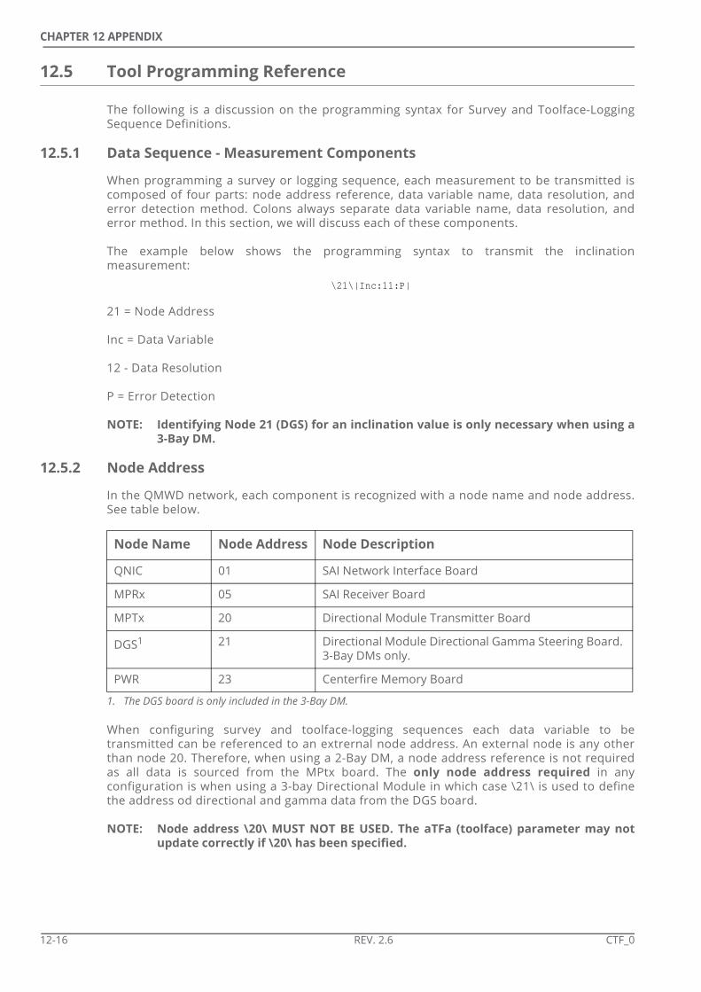
CHAPTER 12 APPENDIX
12.5 Tool Programming Reference
The following is a discussion on the programming syntax for Survey and Toolface-LoggingSequence Definitions.
12.5.1 Data Sequence - Measurement Components
When programming a survey or logging sequence, each measurement to be transmitted iscomposed of four parts: node address reference, data variable name, data resolution, anderror detection method. Colons always separate data variable name, data resolution, anderror method. In this section, we will discuss each of these components.
The example below shows the programming syntax to transmit the inclinationmeasurement:
\21\|Inc:11:P|
21 = Node Address
Inc = Data Variable
12 - Data Resolution
P = Error Detection
NOTE: Identifying Node 21 (DGS) for an inclination value is only necessary when using a3-Bay DM.
12.5.2 Node Address
In the QMWD network, each component is recognized with a node name and node address.See table below.
When configuring survey and toolface-logging sequences each data variable to betransmitted can be referenced to an extrernal node address. An external node is any otherthan node 20. Therefore, when using a 2-Bay DM, a node address reference is not requiredas all data is sourced from the MPtx board. The only node address required in anyconfiguration is when using a 3-bay Directional Module in which case \21\ is used to definethe address od directional and gamma data from the DGS board.
NOTE: Node address \20\ MUST NOT BE USED. The aTFa (toolface) parameter may notupdate correctly if \20\ has been specified.
Node Name Node Address Node Description
QNIC 01 SAI Network Interface Board
MPRx 05 SAI Receiver Board
MPTx 20 Directional Module Transmitter Board
DGS1
1. The DGS board is only included in the 3-Bay DM.
21 Directional Module Directional Gamma Steering Board. 3-Bay DMs only.
PWR 23 Centerfire Memory Board
12-16 REV. 2.6 CTF_0

CHAPTER 12 APPENDIX
12.5.3 Data Variables- Survey Sequences
All directional data for Centerfire operations when using a 2-Bay DM comes from the MPUboard which does not require node identification.
All directional data for Centerfire operations when using a 3-Bay DM comes from thedirectional module DGS board. Thus, the notation to reference the DGS board is \21\.
Directional variables commonly used in the survey sequence are:
Variables from the directional module MPU board do not need a node address reference.Variables from the MPU board commonly used in the survey sequence are:
12.5.4 Data Variables - Toolface/ Logging Sequence
All directional data for Centerfire operations when using a 2-Bay DM comes from the MPUboard which does not require node identification.
All directional data for Centerfire operations when using a 3-Bay DM comes from thedirectional module DGS board. Thus, the notation to reference the DGS board is \21\.
Directional variables commonly used in the toolface-logging sequence are:
All measurement data from the Centerfire comes from the PWR board of the Centerfire. Thisdata is automatically broadcast to the Directional Module MPU and so the the notation toreference the PWR board, “\23\” is NOT required. Measurement variables commonly used inthe toolface-logging sequence are:
Measurement Variable Name
Inclination Inc
Azimuth Azm
Magnetic Dip DipA
Total Magnetic Field MagF
Total Gravity Field Grav
Automatic Toolface aTFA
Rotation Status RotW
Measurement Variable Name
Battery Voltage BatV
Directional Module Temperature Temp
Centerfire Status Register ResR
Measurement Variable Name
Automatic Toolface aTFA
Rotation Status RotW
CTF_0 REV. 2.6 12-17

CHAPTER 12 APPENDIX
12.5.5 ReNF and ReSR
ReNF will only output a '1' if a fault or warning has occurred with the Centerfire. If thisoccurs, recycle the pumps and check the output of ReSR.
ReSR is a 4-byte Centerfire status word that gives its output in hexadecimal format. Forexample:
$8030
The user will need to take this value and write it out in binary, bit 15 is the high order bit. Usethe table below to translate hexadecimal to binary.
In this example $8030 = 1000 0000 0011 0000
Measurement Variable Name
Gamma Ray Gama
400 kHz 19” Phase Difference CCP1
2 MHz 19” Phase Difference CCP2
400 kHz 41” Phase Difference CCP3
2 MHz 41” Phase Difference CCP4
400 kHz 19” Attenuation CCA1
2 MHz 19” Attenuation CCA2
400 kHz 41” Attenuation CCA3
2 MHz 41” Attenuation CCA4
Hex Number
Bit Value
Hex Number
Bit Value
0 0000 8 1000
1 0001 9 1001
2 0010 A 1010
3 0011 B 1011
4 0100 C 1100
5 0101 D 1101
6 0110 E 1110
7 0111 F 1111
Bit Position
15 14 13 12 11 10 9 8 7 6 5 4 3 2 1 0
Binary Digit
1 0 0 0 0 0 0 0 0 0 1 1 0 0 0 0
12-18 REV. 2.6 CTF_0

CHAPTER 12 APPENDIX
The bit position of the binary digits then allows the ResR status table to determine what faultoccurred with the Centerfire based on which bits were set to '1. Therefore the errorsreported:
• D4 = Upper Short Transmitter (TRX 4)Fault
• D5 = Upper Long Transmitter (TRX 2) Fault
• D15 = ReNF is in fault as one or more errors are reported.
NOTE: After power up, any or all warning bits may be active until the initialization com-pletes and recording begins (about 1 minute after power up).
Bit Bit Name Description. Specification
D0 ReLR =1 if Lower Receiver (RX 1) Fault
D1 ReUR =1 if Upper Receiver (RX 2) Fault
D2 RLSX =1 if Lower Short Transmitter (TRX 3) Fault
D3 RLLX =1 if Lower Long Transmitter (TRX 1) Fault
D4 RUSX =1 if Upper Short Transmitter (TRX 4) Fault
D5 RULX =1 if Upper Long Transmitter (TRX 2) Fault
D6 ReBV =1 if Low Battery Warning (Battery Voltage <16 Vdc)
D7 ReBC =1 if Battery Current Limit is exceeded (>0.6 A)
D8 ReDP =1 if At least one of the three DSP power supply voltages not within spec.
D9 ReAQ =1 if No measurement data was recorded during two measure-ment periods.MWD Mode Measurement Period = 9 + Dead TimeTrip Out Measurement Period = 1.8 + Dead Time
D10 ReMW =1 if Less than 10 hours recording time remain
D11 ReMF =1 if Recorder Memory (Flash) errors (since last power on)
D12 ReSF =1 if A Processor fault occurred
D13 ReDF =1 if DSP Failed to initialize (will not acquire data unless power is cycled and the DSP initializes correctly
D14 - Not used
D15 ReNF =1 if any bit of ReSR are = 1
CTF_0 REV. 2.6 12-19

CHAPTER 12 APPENDIX
12.5.6 Data Resolution - General
Data resolution determines how much precision of the measurement is available. Thenumber of bits used and the expected range of the data determine data resolution. Thefollowing table provides recommended data resolution values for data variables commonlyused in survey and logging sequences.
NOTE: It is not required to assign a data resolution value for status flags.
Measurement Variable Name Data Resolution
Inclination Inc 11
Azimuth Azm 12
Magnetic Dip DipA 11
Total Magnetic Field MagF 12
Total Gravity Field Grav 12
Automatic Toolface aTFA 6 (+/- 2.5º)
Battery Voltage BatV 8
Directional Module Temperature Temp 8
Gamma Ray Gama 8 (0-255 API)
12-20 REV. 2.6 CTF_0

CHAPTER 12 APPENDIX
12.5.7 Data Resolution - Phase Difference and Attenuation
For phase difference [PD] and attenuation [ATTN] data, the required transmission resolutionis controlled by the data set and the expected maximum resistivity. As resistivity increasesboth PD and ATTN decrease. Therefore, at high resistivities the values being transmitted willbe very small and a greater transmission resolution will be required to allow differentiationof very small PD or ATTN values.
The following table details the recommended transmission resolution for each data typewith a range of maximum expected resistivities.
NOTE: Tensor Firmware was updated to MpTx v3.03b and MpRx v3.00c in May 2017. Thisupdate limited the range of transmitted CCP values from -360º - +360º to -45º -+315º. As a result, 1 less bit is required for transmission. When using firmwareolder than v3.03b & v3.00c add 1 to the minimum bit rates for CCP values above.
Attenuation Phase Difference
19” 400 kHz (0.1-10 ohm.m) CCA1 19” 400 kHz (0.1-250 ohm.m) CCP1
Expected Res Min Bit Rate Expected Res Min Bit Rate
1 11 1 7
3 13 20 10
5 14 100 13
10 15 250 15
19” 2 MHz (0.1-50 ohm.m) CCA2 19” 2 MHz (0.1-1000 ohm.m) CCP2
Expected Res Min Bit Rate Expected Res Min Bit Rate
1 10 1 7
10 12 50 10
20 14 250 13
50 16 1000 15
41” 400 kHz (0.1-10 ohm.m) CCA3 41” 400 kHz (0.1-500 ohm.m) CCP3
Expected Res Min Bit Rate Expected Res Min Bit Rate
1 11 1 7
3 12 20 11
5 13 200 14
10 14 500 15
41” 2 MHz (0.1-50 ohm.m) CCA4 41” 2 MHz (0.1-2000 ohm.m) CCP4
Expected Res Min Bit Rate Expected Res Min Bit Rate
1 10 1 7
10 12 100 11
20 13 500 13
50 15 2000 15
CTF_0 REV. 2.6 12-21

CHAPTER 12 APPENDIX
12.5.8 Error Detection
here are 2 types of error detection methods that can be used when configuring a datavariable: error correcting code [ECC] and parity. ECC adds 1 to 3 extra bits to the end of adata word in order to assist the receiver in recovering data if errors occur. Parity adds 1 bit tothe end of a data word that is then used by the receiver to detect errors. When configuring adata variable for a sequence, P is used for parity and E is used for error correction code.
NOTE: Parity is the common error detection method for data sequences.
12.5.9 Data Sampling
In Survey Sequences data variables separated by a space only will be acquired at the sametime and lined up for transmission sequentially. Therefore, all of the data transmitted for asurvey will be acquired at the same time from the measurements of the directional sensors.
In Toolface / Logging Sequences data variables separated by a space will be sampled directlybefore they are transmitted. This rule is not true in Repeat Loops however (see below).
12.5.10 Repeat Loops
A group of data variables can be transmitted in a repeat loop through the use of the bracketssymbols '{ }'. See the example below:
10{aTFA:6:P Gama:8:P}
In this example, the sequence is asking the tool to transmit toolface and gamma ray 10 timesbefore ending the loop.
Data variables separated by a space only will be acquired at the same time (at the beginningof the repeat loop) and lined up for transmission sequentially. Data variables separated by asemicolon (;) or a comma (,) will be acquired prior to the requirement for transmission. Thedata from the tool needed for transmission during the Toolface/Logging sequence, at times,does not need to be acquired at the same time. In fact, most data variables should beacquired separately, or as needed.
To force the tool to collect a new sample of data to be transmitted the semi-colon is usedbefore the variable in the data string. See the two examples below:
10 {aTFA:6:P Gama:8:P aTFA:6:P} BatV:8:P
In this example the second toolface will be the same as the first one as the tool has not beeninstructed to resample the data. In addition, the gamma is sampled at the beginning of therepeat loop and so by the time of transmission, especially when drilling speeds are high, thedata may be logged at the wrong depth.
10 {aTFA:6:P;Gama:8:P;aTFA:6:P} BatV:8:P
In this example the gamma and second toolface are preceded by semi-colons which instructsthe tool to collect new data samples. As a result all the transmitted data will be from “fresh”samples.
NOTE: It is STRONGLY recommended to always use semi-colons to separate variables inrepeat loops. Not doing so can result in transmission of repeated and/or ageddata.
NOTE: Although not needed, use of semi colons outside of repeat loops will have no neg-ative effect and so, to maintain consistency, Tensor DT recommends to use semicolons to separate all data variables in Toolface/ Logging sequences.
12-22 REV. 2.6 CTF_0
CHAPTER 12 APPENDIX
NOTE: Failure to include a loop count number before the brackets will create an infiniteloop where the variables inside the brackets will be repeated until the next flowoff.
Nesting can be used to create nested sequences up to 8 nests deep. In the example belowthe system will send 2 x aTFA and then 1 x Gama. This will then be repeated before the BatVis transmitted.
2 {2{aTFA:6:P} Gama:8:P} BatV:8:P
NOTE: The system does not require a semi colon before the Gama variable above. TheGama is handled as a single variable as the aTFA is at a nested level below theGama.
12.5.11 Packed Data Sets
To pack data sets the “+” symbol is used. See the example below.GrvW+TmpW:P
In this example the gravity and temperature warnings are packed into a single word. Evenwith the addition of the parity bit this combination of two single-bit warnings is moreefficient to transmit than it would be to transmit each of the warnings separately.
NOTE: The maximum size allowable for any telemetry word, including a packed word, is21 bits - including any parity or ECC bits.
12.5.12 Grouping
To group data from the same node the '|' symbol is used. See below:\21\|Inc:11:P Azm:12:P DipA:11:P|
In this example, since the inclination, azimuth, and magnetic dip measurements come fromthe DGS board, they can all use the same DGS node address reference \21\ through the useof the '|' symbol.
NOTE: Grouping is only required when using the legacy 3-bay Directional Module.
12.5.13 Special Controls
The following symbols are available for inclusion in a telemetry sequence but they areusually reserved for workshop testing:
The “^” character indicates to transmit the variable without executing a data acquisitionsequence to acquire the data value. This can be sued to force the tool to transmit the valuefrom memory. Consider the following sequence:
10{aTFa:6:P;gama:8:P} ^Temp:8:P
In this example the Directional Sensor is not powered to a acquire the temperature value butinstead the tool will transmit the temperature value that was recorded during the acquisitionof the previous toolface.
The “>” character designates to only acquire the variable but not to transmit it.
CTF_0 REV. 2.6 12-23

CHAPTER 12 APPENDIX
12.6 Gamma Module Replacement
When running the 4.75” or 6.91” tools the Gamma Module is connected to the Centerfirecollar at the workshop and ideally should not be removed or replaced at the rigsite. Thefollowing procedure outlines how to replace the Gamma Module at the rigsite in the eventthat there is a problem with the Gamma Module.
The following points should be considered before completing the procedure:
• Replacement of the Gamma Module should never be completed with the assemblies hanging in the derrick. It should always be completed with the assemblies lying on the deck.
• Every effort should be made to ensure all connections are kept perfectly clean throughout the procedure. This will involve thoroughly flushing the collars to remove any drilling fluids.
• Every effort should be made to ensure all connections are kept perfectly dry throughout the procedure.
12.6.1 Gamma Module Removal
1. Break the connection between the Centerfire Collar and the Gamma Collar on the rigfloor.
NOTE: Do not remove the Gamma Collar on the rigfloor.
2. Lay the assembly horizontally on blocks so that there is enough space to remove theGamma Collar from the Centerfire Collar.
3. Unscrew and remove the Gamma Collar, taking extra care to maintain the perfect align-ment of the Collar as it slides over the Gamma Module. Lifting straps can be used to helpmaintain the alignment and ensure the weight of the collar is never transferred to theGamma Module.
NOTE: Interconnect Bowsprings can become very sharp during downhole use. Alwayswear gloves when handling the Bowspring Interconnect.
4. Thoroughly clean and dry the bore of the Centerfire Collar around the Gamma Centralizer.
5. Unscrew the Gamma Module from the Gamma Centralizer using an adjustable spanner onthe flats on the housing. The Gamma Module should be maintained and tested accordingto the Scinturian 2 Gamma Module Maintenance Manual (TGAM_M).
12.6.2 Gamma Module Attachment
1. Inspect the uphole connector of the Gamma Module to ensure it is free of dirt or debris.
2. Inspect the connector of the Gamma Centralizer to ensure it is free of dirt or debris.
12-24 REV. 2.6 CTF_0

CHAPTER 12 APPENDIX
3. Apply grease to the 220 O-rings (422900/ 381611) on the uphole connector of the GammaModule.
4. Insert the Gamma Module into the Gamma Centralizer taking care as the module passesthe threads on the bottom connection of the Centerfire Collar.
NOTE: The Gamma Module should be held perfectly level as it is inserted into the Central-izer. Minimal force is required to screw the Module into the Centralizer. Remove,and investigate the reason for difficulty if any resistance is met when screwing theModule into the Centralizer.
5. Screw the Gamma Module into the Gamma Centralizer using an adjustable wrench on theGamma Module flats and torque to 90-100 lbf.ft (120-135 Nm).
6. Attach an Interconnect to the bottom of the Gamma Module.
NOTE: The Interconnect should be fitted with new Bowsprings or a new Finned Sleeve,with the fins cut to the internal diameter of the collar, to ensure the Gamma Mod-ule is centralised and supported within the Gamma Collar.
7. Check the Spear Point ( (981925)). The Point must be torqued to the Base. If loose, removethe Spear Point, clean the threads and re-install with Loctite 272 torquing to 50 lbf.ft / 70Nm.
8. Screw the Spear Point (981925) onto the Interconnect and torque to 50 lbf.ft / 70 Nm.
12.6.3 Gamma Collar Connection
The following procedure is used to connect the Gamma Collar to the Centerfire Collar.
1. Inspect the threads on the Centerfire Collar and the Gamma Collar to check they are per-fectly clean.
2. Apply Molykote Antisieze Compound (400193) to the threads on the Gamma Collar andCenterfire Collar and to the OD of the Bowsprings/ Rubber Finned Sleeve on the Intercon-nect.
3. Position the Centerfire Collar so that the Gamma Collar will be able to be slid over theGamma Module while keeping the Gamma Collar horizontal so as to apply no stress to theGamma Module.Use of a lifting strap (or 2 x lifting straps) to maintain the Gamma Collar in the correctalignment can aid the process.
4. While supporting the Gamma Collar and keeping it perfectly horizontal slide it over theGamma Module until it makes up to the thread of the Centerfire Collar.
NOTE: Extra care should be taken to ensure the Gamma Module is not damaged duringconnection of the Gamma Collar. The Collar should be installed slowly and itsalignment continually monitored to ensure no stress is applied to the Gamma
CTF_0 REV. 2.6 12-25

CHAPTER 12 APPENDIX
Module.
5. Screw the Gamma Collar into the Centerfire Collar.
6. Lift the assembly to the rigfloor and make up the connection to 4.75” -9600 lbf.ft/ 13000Nm, 6.91” - 24000 lbf.ft/ 32500 Nm.
12-26 REV. 2.6 CTF_0
CHAPTER
INDEX
AAcquisition Cycle 1-7Alignment Tool see Interconnect Alignment ToolAntenna Array 1-2Assembly see Toolstring ConnectionATEX Certification 6-2AttenuationSpecifications 2-2BBatteries
dealing with a damaged battery pack 12-2decomposition products 12-1passivation 12-1personnel safety 12-6recharging 12-2ruptured 12-2shelf-life 12-1storage area 12-1storage environment 12-1storage temperature 12-1
BatteryHigh Temperature 4-5Recommendations 5-1Standard 4-5
Battery - GeneralSafety S-1
Battery depletion, workshop procedure 12-2Battery Disposal S-2Battery Jumper Plug 4-42, 5-30Battery Life Calculations 4-4Battery Test 4-6Beryllium Copper S-1BHA Data, LogView II 7-3Borehole Compensation 1-7CCalibration, LogView II 7-4Casing
Logging through 8-1Shoes 8-1
Cold Climates 6-2
Comms Port see Data Dump PortCommunications
Overview 4-24Test 4-26
Compensationsee Borehole Compensation
Components 1-2Conductivity
Meter 8-4Conductivity, LogView II 7-8Configuration
Load 6-17Connection see Toolstring ConnectionCopy Memory 4-52DDamaged battery see Batteries 12-2DAO 6-9Data Dump Cover 6-24Data Dump Port
Voltage Check 4-42, 6-14Data Presentation 8-3Data Sets 5-7
LogView II 7-7Dead Time 5-24Depth Tracking 8-2DGS 4-46Directional Module 4-11Dogleg Severity see Mechanical SpecificationsDownload see Copy MemoryDrill Collar Specifications see Mechanical Specifica-tions 2-4Driller’s Assembly Offset 6-9Drilling Mode, LogView II 7-6Driver see USB DriverDump Port see Data Dump PortEElectrical Equipment Disposal S-2End of Run Check List 3-4Environmental Specifications 2-3Erase Memory 4-49
CTF_0 REV. 2.6 13-1

SECTION 13: INDEX
FFirmware Upgrades 4-25Float Valve 6-7Flow Rate 2-4GGamma Collar Connection 12-25Gamma Module Replacement 12-24Gamma Processing Controls 5-24Gamma Ray Tool Specifications see Tool Specifica-tionsHHatch Cover
Inspection 4-20Header see Log HeaderHelix End
O-ring 4-14High Temperature Battery Packs
Rigfloor 6-13Highside see ToolfaceHot Climates 6-2IInterconnect Alignment Tool 4-35Interconnect Assembly 4-33JJ-latch 6-12LLaying down the Centerfire 9-4Laying Down the MWD Tool 9-4Lifting Bail 6-11Log Header 8-3Log Plot Data 7-2Log Presentation 8-3Logging Check List 3-3Lost Circulation Material 2-3MManual Handling S-1Measurement Datums 5-32Measurement Offsets 5-31Measurement Sequence 1-7Memory
Capacity 2-2CopyTest 4-46
Memory Dump Port see Data Dump portMemory I/O 4-47, 6-21MPTx 4-46Mud Data, LogView II 7-4Mud Solids see Environmental SpecificationsMud Viscosity see Environmental SpecificationsMud Weight Specification see Environmental Specifi-cationsNNode Status 4-41, 4-44, 6-16Nodes 5-6OOffsets see Measurement Offsets
Oxide layer see Batteries, passivationPParts Lists 11-1PCD 4-46Phase Difference
Specifications 2-2Poppet Tip
Installation 4-18PRD 4-46problem solving. See troubleshooting 10-1Programming 5-5, 6-15Programming Top 4-39Pulser
Electrical Test 4-15Insertion into Centerfire 4-38Inspection 4-14
PWR Processing Controls 5-24QqWD32Server 4-28, 4-40RRacking-back 9-3Raw File
View 4-50Recorder Delay 5-24Recorder see MemoryReNF 5-9, 12-18Repeat Sections 8-4ReSR 5-9, 12-18Rig Floor
Safety 6-4Rigsite Storage 4-1Run Data, LogView II 7-5SSafety Symbols
See Warning Symbols.Sand Content see Environmental SpecificationsScribeline
DAO 6-9MWD String 5-29
Sensor Specifications. See Tool SpecificationsSet Tool Time 4-48, 6-21, 6-22Shallow Hole Test 6-29Shock Limit. See Environmental SpecificationsSoftware
Installation 4-22Spectrum Battery 4-5Start Up Check List 3-2Storage 4-1String Test 4-32Subs Data, LogView II 7-3Surface Receiver Controls 6-29Survey Offset 5-33TTap Test 4-17, 4-45Temperature limit, lithium batteries 12-2Temperature Specification 2-3TFO see Toolface
13-2 REV. 2.6 CTF_0

SECTION 13: INDEX
Tong Placement 6-6Tool Joint Make-up Torque 2-4Tool Programming see ProgrammingTool Specifications
Gamma Sensor 2-3Temperature Limit 2-3
Tool Time see Set Tool TimeToolface
Set Up 5-29Toolstring Connection 4-36, 5-2Transport 4-1troubleshooting 10-1UUSB Driver 4-23VVertical Resolution 2-2Vibration Limit see Environmental SpecificationsVoltage Check see Battery TestWWarning Symbols S-3Wear Band
Diameters 4-21Weather Extremes 6-2Weights and Dimensions 2-5Well Data, LogView II 7-2Wet Connect
Female - Preparation 6-7Male - Test 4-16
ZZero Point see Survey Offset
CTF_0 REV. 2.6 13-3

SECTION 13: INDEX
THIS PAGE INTENTIONALLY LEFT BLANK
13-4 REV. 2.6 CTF_0