centaflex-a - centa power transmission - · pdf filereliable electric insulation. ... the...
TRANSCRIPT

CENTA PRODUKT DOKUMENTATION
CENTAFLEX-A
CENTA POWER TRANSMISSION
CF-A
-17-1
5
Is this PDF up to date?
click here for an update check!
ENGLISH

CENTAFLEX-A
CENTA PRODUCT DOCUMENTATION
CF-A-EN-17-15 | PAGE 2 | PUBLISHED 20. MARCH 2017 | MAIN MENU → CHECK FOR UPDATES
COMPONENTS/ADAPTATION
Rubber elementsPage 06
HubsPage 07
FlangesPage 07
Drive shaftsPage 07
Torque limitersPage 07
SYSTEM
At a glancePage 03
AREAS OF APPLICATION
Product selection:
Which coupling for
which purpose?Page 10
TECHNICAL DATA
Product application:
Which feature for
which coupling?Page 13
VERSATILE SUPERSTAR. FOR ALL APPLICATIONS.
Is this PDF up to date?
click here for an update check!
SERVICE
Explanation of the technical data
Page APP-1
Contact
Page APP-6

CENTA PRODUCT DOCUMENTATION
CF-A-EN-17-15 | PAGE 3 | PUBLISHED 20. MARCH 2017 | MAIN MENU → CHECK FOR UPDATES
CENTAFLEX-AAT A GLANCE
Features
High flexibility in all directions
High adaptability to torsional flexibility
High design flexibility
Fail-safe device integration
Areas of application
Torque range
0.01 to 12.5 kNm
For safe transmission of high torques
and long lifespan with maximum
design flexibility
The CENTAFLEX-A presents itself as a versatile superstar when it comes to coping with sophisticated misalignment compensation, fail-safe decoupling of torsional vibrations and reliable electric insulation. Complete with maximum design flexibility.
As the bestseller among all of CENTA’s couplings, it is based on a highly elastic rubber el-ement with an integrated fail-safe device that allows for adequate and appropriate appli-cation designs. The element is available in a variety of materials and different degrees of Shore hardness. This enables the torsional flexibility of the couplings to be adapted with utmost variability to the specific application. It features a radial-axial screwing concept, unique in this market, and simplifies the mounting of these couplings significantly.
The CENTAFLEX-A is available in a number of different designs as a coupling or a drive shaft (steel, carbon-fibre or glass-fibre designs) as well as in axially plug-in design. Quick replacement of the low-maintenance rubber element is made possible by a split-design replacement element for radial mounting. Combined with a wide range of adapt-ers, flanges, and hubs, the CENTAFLEX-A adapts optimally to each installation thereby guaranteeing seamless coverage for torques up to 12.5 kNm.

LEADING BY INNOVATION
CENTA PRODUCT DOCUMENTATION
CF-A-EN-17-15 | PAGE 4 | PUBLISHED 20. MARCH 2017 | MAIN MENU → CHECK FOR UPDATES
QUALITYMODULARITYTORSIONAL FLEXIBILITYCOMPENSATION OF MISALIGNMENTS
When the going gets tough, quality
is priceless. With an exemplary
Quality Management, CENTA en-
sures products that withstand the
roughest assignments. CENTA’s
coupling systems are more than
the sum of their parts. CENTA
entertains the vision of intelligent
products that meet the highest
requirements in terms of design
and quality.
The rubber element of the
CENTAFLEX-A enables an adequate
and appropriate design solution
for practically any application with
very little effort. The versatile su-
perstar among the CENTA products
is available as a coupling and as a
drive shaft (steel, carbon fibre or
glass-fibre design).
Combined with a wide range of
adapters, flanges and hubs, the
CENTAFLEX-A can be customized
to any kind of mounting and ap-
plication condition.
The rubber elements for the
CENTAFLEX-A are available in
different degrees of Shore hard-
ness. This enables the torsional
flexibility of the couplings to be
adapted with utmost variability to
the specific application. Torsional
vibrations and impacts are reliably
dampened.
The couplings of the CENTAFLEX-A
series compensate for significant
misalignments in axial, radial and
angular directions. They are the
ideal solution for applications with
demanding misalignments.
The axial-radial screwing connec-
tion for the CENTAFLEX-A, unique
in this market, eases the assembly
significantly; moreover, it ensures
the application of pre-pressure
on the rubber columns and is
advantageous for the performance
capabilities and service-life of the
coupling. In addition, all designs
are available as plug-in versions
for axial assembly. Quick replace-
ment of the low-maintenance
rubber element is guaranteed due
to a split version of the rubber ele-
ment, which is assembled radially.
ASSEMBLY

CENTAFLEX-A
CENTA PRODUCT DOCUMENTATION
CF-A-EN-17-15 | PAGE 5 | PUBLISHED 20. MARCH 2017 | MAIN MENU → CHECK FOR UPDATES
COMPONENTSADAPTATION

CENTA PRODUCT DOCUMENTATION
CF-A-EN-17-15 | PAGE 6 | PUBLISHED 20. MARCH 2017 | MAIN MENU → CHECK FOR UPDATES
CENTAFLEX-ACOMPONENTS
RUBBER ELEMENTS
The CENTAFLEX-A rubber elements are made of high-
quality natural rubber or of silicone – for use at very high
ambient temperatures – and feature vulcanized jaws for
fastening to the drive side resp. power take-off side. By
covering the jaws in the circumferential direction, the
coupling elements are fail-safe.
The axial-radial screwing connection for the CENTAFLEX-A,
unique in this market, eases the assembly significantly;
moreover, it ensures the application of pre-pressure on the
rubber columns and is advantageous for the performance
capabilities and service-life of the coupling.
The CENTAFLEX-A rubber elements are available in various
designs either as a screw-type or as an axially plug-in
version. To allow quick replacement of the low-
maintenance rubber element, we offer a split version of
the rubber element, which is assembled radially.

CENTA PRODUCT DOCUMENTATION
CF-A-EN-17-15 | PAGE 7 | PUBLISHED 20. MARCH 2017 | MAIN MENU → CHECK FOR UPDATES
CENTAFLEX-AADAPTATION
HUBS
We offer all standard connections, such as evolute
splines, flange connections, clamping sets, keyway
connections and oil press fits. In addition, CENTA
has developed the CENTALOC clamping hub, a shaft-
hub-connection, which is completely free of backlash
and has proven itself in thousands of applications.
The clamping system prevents wear and tear due to
fretting corrosion or deflection of the gearing and is
available for all CENTAFLEX-A couplings.
FLANGES
The CENTAFLEX-A is available for all SAE flywheels
as well as for non-standard flywheels. Flanges can be
obtained for all connections and can be adapted to any
existing drive or PTO elements as desired.
TUBES
The homokinetic version of the CENTAFLEX-A can be
delivered in any requested length and thereby adap-
ted to specific mounting conditions. Short shafts are
made with tubes of round steel, longer shafts (up to 6
metres and special designs of even greater length) are
bridged by a thin-walled precision steel tube.
In addition, CENTA has developed light-weight drive
shafts made of carbon-fibre reinforced plastic. The
rigidity and stability is comparable to steel, but the
weight is significantly less, which is an advantage es-
pecially for bend-critical applications. For applications
which require extremely high insulation values, the
CENTAFLEX-A can be delivered with a glass-fibre tube.
TORQUE LIMITERS
Load holding torque limiters are available for all
CENTAFLEX-A designs, suitable for mounting either
in the middle tube as well as on the generator shaft.
Supplied with pre-set slip-through torque and
individual calibration protocol.

CENTAFLEX-A
CENTA PRODUCT DOCUMENTATION
CF-A-EN-17-15 | PAGE 8 | PUBLISHED 20. MARCH 2017 | MAIN MENU → CHECK FOR UPDATES
TYPES
Which product for your purpose?
We will gladly assist → www.centa.info/contact

CENTA PRODUCT DOCUMENTATION
CF-A-EN-17-15 | PAGE 9 | PUBLISHED 20. MARCH 2017 | MAIN MENU → CHECK FOR UPDATES
Rubber element on which the Type series is based. Made of high-quality natural rubber or silicone and avail-able in various degrees of Shore hardness.
Type S for plug-in assembly.
CouplingType 0 and 0–S
Rubber element with simple flange plate, which can be adopted to any standard and non-standard flywheel as well as any other element. Suitable for combustion engines and other applications.
Type S for plug-in assembly.
CouplingType 3 and 3–S
Highly flexible drive shaft, available in any desired length and with variable connection elements that can be cus-tomized to any kind of mounting and application condition. Extremely ver-satile and cost-effective type. Suitable for low torques and small distances.
For applications with high torques and large distances, the shafts feature additionally an accurate, low mainte-nance centering of the intermediate tube. CENTA always considers the individual operating conditions before choosing a type.
Drive shaftType G / GB / GZ
Rubber element with hub for drive resp. power take-off side. For con-nection to already existing drivetrain elements such as flywheels, pulleys or brake discs, friction or turbo clutches, freewheel clutches, cogwheels, etc.
Type S for plug-in assembly.
CouplingType 1 and 1–S
Rubber element with hub for drive resp. power take-off side. Intended for all applications in general mechan-ical engineering.
Type S for plug-in assembly.
CouplingType 2 and 2–S
CENTAFLEX-ATYPES

CENTAFLEX-A
CENTA PRODUCT DOCUMENTATION
CF-A-EN-17-15 | PAGE 10 | PUBLISHED 20. MARCH 2017 | MAIN MENU → CHECK FOR UPDATES
Which product for your purpose?
We will gladly assist → www.centa.info/contact
APPLICATIONS

CENTA PRODUCT DOCUMENTATION
CF-A-EN-17-15 | PAGE 11 | PUBLISHED 20. MARCH 2017 | MAIN MENU → CHECK FOR UPDATES
Which product for your purpose?
We will gladly assist → www.centa.info/contact
GEARBOX GEARBOX
PTO
ENGINE
PTO
ENGINE GEARBOX
ENGINE GEARBOX
COMPRESSOR
GEARBOX
HYDRAULIC ENGINE
ELECTRIC ENGINE GEARBOX EDDY-CURRENT
BRAKE
ENGINE TO
BE TESTED
TEST BENCH
RAIL APPLICATIONS
CENTAFLEX-AAPPLICATIONS
E-MOTOR E-MOTOR E-MOTOR
INDUSTRY APPLICATIONS
CENTA PRODUCT DOCUMENTATION
CF-A-EN-17-15 | PAGE 12 | PUBLISHED 20. MARCH 2017 | MAIN MENU → CHECK FOR UPDATES
Which product for your purpose?
We will gladly assist → www.centa.info/contact
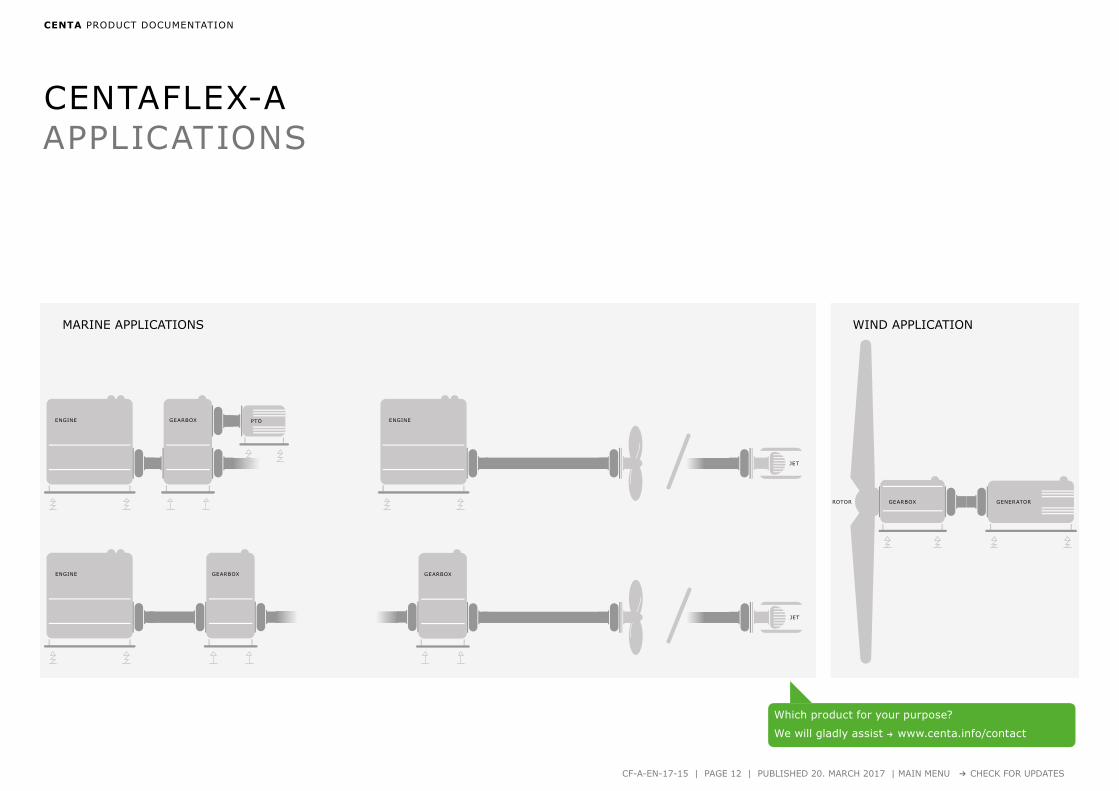
ENGINE GEARBOX
ENGINE PTO ENGINE
JET
GEARBOX
JET
MARINE APPLICATIONS WIND APPLICATION
GENERATORGEARBOXROTOR
GEARBOX
CENTAFLEX-AAPPLICATIONS
CENTAFLEX-A
CENTA PRODUCT DOCUMENTATION
CF-A-EN-17-15 | PAGE 13 | PUBLISHED 20. MARCH 2017 | MAIN MENU → CHECK FOR UPDATES
TECHNICAL DATA
Questions on product selection?
We will gladly assist → www.centa.info/contact

CENTAFLEX-A
CENTA PRODUCT DOCUMENTATION
CF-A-EN-17-15 | PAGE 14 | PUBLISHED 20. MARCH 2017 | MAIN MENU → CHECK FOR UPDATES
SERIES 0 – 3
TECHNICAL DATA
Sizes 1–28 ................................ Page 15
Sizes 30–800 ............................ Page 16
DIMENSIONS
Type 0 Sizes 1–800 ...............................Page 17
Type 0–S Sizes 1-600 .............................. Page 18
Type 1 Sizes 1–800 .............................. Page 19
Type 1–S Sizes 1-600 .............................. Page 20
Type 2 Sizes 1–800 ...............................Page 21
Type 2–S Sizes 1-600 .............................. Page 22
Type 3 Sizes 8–90 ................................ Page 23
Sizes 140–800 .......................... Page 24
Type 3-S Sizes 8-90 ................................ Page 25
Sizes 140–600 .......................... Page 26

↓
CENTAFLEX-A
150
0,010 0,025 0,005 60,09 0,60
10000 20,0266
1,50,105
30,00021
60 0,14 0,78 0,0380 0,150 0,00030
250
0,020 0,060 0,010 100,18 0,60
8000 30,0154
1,50,105
30,00021
60 0,29 0,78 0,0220 0,150 0,00030
450
0,050 0,125 0,020 150,55 0,60
7000 30,0525
1,50,350
30,00168
60 0,85 0,78 0,0750 0,500 0,00240
850
0,100 0,280 0,040 250,90 0,80
6500 40,0525
20,350
30,00252
60 1,50 1,00 0,0750 0,500 0,00360
1250
0,140 0,360 0,050 302,70 0,80
6500 40,1750
20,700
20,00630
60 4,40 1,00 0,2500 1,000 0,00900
1650
0,200 0,560 0,080 402,00 0,80
6000 50,1550
20,300
30,01750
60 3,40 1,00 0,3200 0,600 0,01900
2250
0,275 0,750 0,100 506,10 0,80
6000 50,3100
20,850
20,02100
60 9,00 1,00 0,5000 1,500 0,02400
2550
0,315 0,875 0,125 682,80 0,80
5000 50,2100
20,400
30,01900
60 4,50 1,00 0,3950 0,800 0,02100
2850
0,420 1,200 0,150 757,50 0,80
5000 50,4000
21,000
20,02400
60 12,00 1,00 0,7000 1,800 0,02800
1 2* 3 4 5 6 7 8 9** 10 11 12 13 14 15
→
CENTA PRODUCT DOCUMENTATION
CF-A-EN-17-15 | PAGE 15 | PUBLISHED 20. MARCH 2017 | MAIN MENU → CHECK FOR UPDATES
TECHNICAL DATA SIZES 1–28
* values for 70 and 75 Shore on request** At 60 Shore.
SIZES 30–800
Size Rubber quality
Nominal torque
Maximum torque
Continuous vibratory torque
Permissible power loss
Dynamic torsional stiffness
Relative damping
Speed Permissible axial
displacement
Axial stiffness
Permissible radial
displacement
Radial stiffness
Permissible angular
displacement
Angular stiffness
[Shore A] TKN TKmax TKW PKV CTdyn Ψ nmax ΔKa Ca ΔKr Cr ΔKW CW
[kNm] [kNm] [kNm] [W] [kNm/rad] [min-1] [mm] [kN/mm] [mm] [kN/mm] [°] [kNm/°]

↓
CENTAFLEX-A
3050
0,500 1,400 0,200 804,80 0,80
4000 50,2250
20,500
30,01800
60 7,80 1,00 0,4600 1,000 0,02500
5050
0,700 2,100 0,300 9012,00 0,80
4000 50,4750
21,450
20,03000
60 19,00 1,00 0,8500 2,350 0,04000
8050
0,900 2,100 0,320 10016,00 0,80
4000 30,4500
1,51,600
20,03800
60 25,00 1,00 0,7500 2,400 0,05000
9050
1,100 3,150 0,450 12010,50 0,80
3600 50,3150
20,800
30,02800
60 16,00 1,00 0,6500 1,500 0,03500
14050
1,700 4,900 0,700 15026,50 0,80
3600 50,5800
21,500
20,04200
60 40,00 1,00 1,0000 2,500 0,06700
20050
2,400 6,000 0,960 17038,70 1,05
3000 50,6400
21,500
20,06200
60 60,00 1,10 1,1000 2,650 0,06800
25050
3,000 8,750 1,250 20043,00 0,80
3000 50,6600
21,700
20,07100
60 77,00 1,00 1,2000 2,700 0,10500
40050
5,000 12,500 2,000 24075,00 1,05
2500 50,7000
21,900
20,09500
60 120,00 1,10 1,3500 3,000 0,13500
60050
8,000 20,000 3,200 330105,00 1,05
2500 50,8500
22,500
20,13000
60 160,00 1,10 1,5500 3,700 0,20000
80050
12,500 30,000 5,000 420160,00 1,05
2300 51,1000
23,300
20,43000
60 243,00 1,10 2,0000 5,000 0,56000
1 2* 3 4 5 6 7 8 9** 10 11 12 13 14 15
→
CENTA PRODUCT DOCUMENTATION
CF-A-EN-17-15 | PAGE 16 | PUBLISHED 20. MARCH 2017 | MAIN MENU → CHECK FOR UPDATES
TECHNICAL DATA SIZES 30–800
* values for 70 and 75 Shore on request** At 60 Shore.
SIZES 1–28
Size Rubber quality
Nominal torque
Maximum torque
Continuous vibratory torque
Permissible power loss
Dynamic torsional stiffness
Relative damping
Speed Permissible axial
displacement
Axial stiffness
Permissible radial
displacement
Radial stiffness
Permissible angular
displacement
Angular stiffness
[Shore A] TKN TKmax TKW PKV CTdyn Ψ nmax ΔKa Ca ΔKr Cr ΔKW CW
[kNm] [kNm] [kNm] [W] [kNm/rad] [min-1] [mm] [kN/mm] [mm] [kN/mm] [°] [kNm/°]

S
A
E
G
J1
J2
TK -Y
x2
x3
d3
x4
N1
x4
x1x5
x1 x1
P2
T2
R2
T1R1
P1
↓
CENTAFLEX-A
1 24 56 22 11 30 18 5 6,2 6,2 2 10,5 10,5 - - - - - 44 2x180° 0,00002 0,00002 0,04 0,05
2 24 85 20 10 40 12 14,2 8,2 8,2 4 13,5 13,5 4 9 3 - 3 68 2x180° 0,00009 0,00012 0,08 0,11
4 28 100 24 12 45 17 18,5 8,2 8,2 4 13,5 13,5 4 9 3 - 3 80 3x120° 0,00020 0,00020 0,13 0,15
8 32 120 28 14 60 20,5 20,5 10,2 10,2 4 16,5 16,5 4 12 4 10 3 100 3x120° 0,0006 0,0005 0,25 0,25
12 32 122 28 14 60 20,5 20,5 10,2 10,2 4 16,5 16,5 4 12 4 10 3 100 4x90° 0,0007 0,0005 0,28 0,32
16 42 150 36 18 70 23,5 25,2 12,2 12,2 6 18,1 18,3 5 18 6 13,5 5 125 3x120° 0,0015 0,0014 0,4 0,5
22 42 150 36 18 70 23,5 25,2 12,2 12,2 6 18,1 18,3 5 18 6 13,5 5 125 4x90° 0,0019 0,0016 0,5 0,6
25 46 170 40 20 85 26 26 14,2 14,2 6 21,1 22 5 18 5 14 5 140 3x120° 0,0027 0,0025 0,6 0,6
28 46 170 40 20 85 26 26 14,2 14,2 6 21,1 22 5 18 5 14 5 140 4x90° 0,0034 0,0030 0,7 0,8
30 58 200 50 25 100 34,5 33,5 16,2 16,2 8 24,1 24,5 5 20 6 18 5 165 3x120° 0,0065 0,0060 1,0 1,1
50 58 200 50 25 100 34,5 33,5 16,2 16,2 8 24,1 24,5 5 20 6 18 5 165 4x90° 0,0081 0,0072 1,3 1,2
80 65 205 61 30,5 100 34,5 34,5 16,5 16,5 4 24,1 24,5 5 20 6 18 5 165 4x90° 0,0095 0,0092 1,4 1,6
90 70 260 62 31 125 45 46 20,2 20,2 8 30,5 31 8 25 5 22,5 5 215 3x120° 0,0237 0,0213 2,2 2,3
140 70 260 62 31 125 45 46 20,2 20,2 8 30,5 31 8 25 5 22,5 5 215 4x90° 0,0286 0,0251 2,7 2,6
200 80 300 72 36 145 44 45,5 20,2 20,2 8 32 32 8 25 5 22,5 5 250 4x90° 0,0481 0,0471 3,4 3,7
250 85 340 7722,5
160 60 60 20,2 20,2 8 30,5 * 10 30 8 - 8 280 4x90° 0,081 0,086 4,5 5,554,5
400 105 370 9528,5
170 67 71 24,2 20,2 10 42,5 * 10 40 8 - 8 300 4x90° 0,155 0,154 7,5 8,266,5
600 125 470 11033
200 84 87 27,2 24,2 15 50 * 10 60 9 - 9 380 4x90° 0,464 0,363 13,8 13,377
800 145 545 128
29
230 112 103 22,2 22,2 17 45 * 10 45 9 - 9370 4x90°
0,586 0,637 20,1 24,164470 4x90°99
CENTA PRODUCT DOCUMENTATION
CF-A-EN-17-15 | PAGE 17 | PUBLISHED 20. MARCH 2017 | MAIN MENU → CHECK FOR UPDATES
DIMENSIONS SIZES 1–800
TYPE 0
* on request
Size Dimensions Mass moments of inertia and massesA d3 E G N1 P1 P2 R1 R2 S T1 T2 x1 x2 x3 x4 x5 TK Y J1 J2 m1 m2
[kgm2] [kg]

E
S
A
G
J1
J2
TK -Y
d3
x4
N1
x4
x5
x1 x1
P2
T2
R2
Ts
↓
CENTAFLEX-A
1 24 56 22 11 30 5 6,2 2 10,5 10 - - - 44 2x180° 0,00004 0,00002 0,06 0,05
2 24 85 20 10 40 14,2 8,2 4 13,5 14 4 - 3 68 2x180° 0,00011 0,00012 0,1 0,11
4 28 100 24 12 45 18,5 8,2 4 13,5 14 4 - 3 80 3x120° 0,00023 0,00020 0,15 0,15
8 32 120 28 14 60 20,5 10,2 4 16,5 17,1 4 10 3 100 3x120° 0,0007 0,0005 0,29 0,25
12 32 122 28 14 60 20,5 10,2 4 16,5 17,1 4 10 3 100 4x90° 0,0010 0,0005 0,32 0,32
16 42 150 36 18 70 25,2 12,2 6 18,3 19,1 5 13,5 5 125 3x120° 0,0019 0,0014 0,5 0,5
22 42 150 36 18 70 25,2 12,2 6 18,3 19,1 5 13,5 5 125 4x90° 0,0026 0,0016 0,6 0,6
25 46 170 40 20 85 26 14,2 6 22 22 5 14 5 140 3x120° 0,0036 0,0025 0,8 0,6
28 46 170 40 20 85 26 14,2 6 22 22,5 5 14 5 140 4x90° 0,0046 0,0030 0,9 0,8
30 58 200 50 25 100 33,5 16,2 8 24,5 25 5 18 5 165 3x120° 0,0083 0,0060 1,3 1,1
50 58 200 50 25 100 33,5 16,2 8 24,5 25,1 5 18 5 165 4x90° 0,0106 0,0072 1,7 1,2
80 65 205 61 30,5 100 34,5 16,5 4 24,5 25,1 5 18 5 165 4x90° 0,0119 0,0092 1,7 1,6
90 70 260 62 31 125 46 20,2 8 31 32 8 22,5 5 215 3x120° 0,0294 0,0213 2,7 2,3
140 70 260 62 31 125 46 20,2 8 31 32,1 8 22,5 5 215 4x90° 0,0368 0,0251 3,4 2,6
200 80 300 72 36 145 45,5 20,2 8 32 32,1 8 22,5 5 250 4x90° 0,0596 0,0471 4,2 3,7
250 85 340 7722,5
160 60 20,2 8 * 32,1 10 - 8 280 4x90° 0,091 0,086 5 5,554,5
400 105 370 9528,5
170 71 20,2 10 * 45 10 - 8 300 4x90° 0,204 0,154 9,6 8,266,5
600 125 470 11033
200 87 24,2 15 * 53 10 - 9 380 4x90° 0,569 0,363 16,5 13,377
CENTA PRODUCT DOCUMENTATION
CF-A-EN-17-15 | PAGE 18 | PUBLISHED 20. MARCH 2017 | MAIN MENU → CHECK FOR UPDATES
DIMENSIONS SIZES 1–600
TYPE 0–S
* on request
Size Dimensions Mass moments of inertia and massesA d3 E G N1 P2 R2 S T2 Ts x1 x4 x5 TK Y J1 J2 m1 m2
[kgm2] [kg]

A
S
E
J2
J1
d3
N1
TK -Y
x 2
x6
L1
d1
B1
C1
x1
M1
↓
CENTAFLEX-A
1 24 7 26 19 56 22 24 M 6 30 2 - - - 44 2x180° 0,00002 0,00003 0,04 0,13
2 24 8 32 26 85 20 28 M 8 40 4 - - - 68 2x180° 0,00009 0,00016 0,08 0,26
4 28 8 34 30 100 24 30 M 8 45 4 - - - 80 3x120° 0,00020 0,00027 0,13 0,35
8 32 10 46 38 120 28 42 M 10 60 4 - - - 100 3x120° 0,0006 0,0008 0,25 0,79
12 32 10 46 38 122 28 42 M 10 60 4 - - - 100 4x90° 0,0007 0,0008 0,28 0,85
16 42 12 56 48 150 36 50 M 12 70 6 5 18 4 125 3x120° 0,0015 0,0021 0,40 1,26
22 42 12 56 48 150 36 50 M 12 70 6 5 18 4 125 4x90° 0,0019 0,0023 0,50 1,35
25 46 14 61 55 170 40 55 M 14 85 6 5 18 5 140 3x120° 0,0027 0,0042 0,60 1,96
28 46 14 61 55 170 40 55 M 14 85 6 5 18 5 140 4x90° 0,0034 0,0047 0,70 2,10
30 58 16 74 65 200 50 66 M 16 100 8 5 20 5 165 3x120° 0,0065 0,0100 1,0 3,4
50 58 16 74 65 200 50 66 M 16 100 8 5 20 5 165 4x90° 0,0081 0,0112 1,3 3,4
80 65 16 75,5 65 205 61 66 M 16 100 9,5 5 20 5 165 4x90° 0,0095 0,0132 1,4 3,8
90 70 20 88 85 260 62 80 M 20 125 8 8 25 5 215 3x120° 0,0237 0,0327 2,2 6,3
140 70 20 88 85 260 62 80 M 20 125 8 8 25 5 215 4x90° 0,0286 0,0364 2,7 6,6
200 80 20 102 105 300 72 94 M 20 145 8 8 25 5 250 4x90° 0,0481 0,0696 3,4 9,3
250 85 20 108 115 340 77 100 M 20 160 8 10 30 6 280 4x90° 0,081 0,121 4,5 12,7
400 105 28 135 120 370 95 125 M 24 170 10 10 40 6 300 4x90° 0,155 0,212 7,5 18,9
600 125 30 170 140 470 110 155 M 27 200 15 10 60 5 380 4x90° 0,464 0,502 13,8 32,1
800 145 22 182 165 545 128 165 M 22 230 17 - - -370 4x90°
0,586 0,888 20,1 49,2470 4x90°
CENTA PRODUCT DOCUMENTATION
CF-A-EN-17-15 | PAGE 19 | PUBLISHED 20. MARCH 2017 | MAIN MENU → CHECK FOR UPDATES
DIMENSIONS
TYPE 1
SIZES 1–800
Size Dimensions Mass moments of inertia and massesA B1 C1 d1max d3 E L1 M1 N1 S x1 x2 x6 TK Y J1 J2 m1 m2
[kgm2] [kg]

E
S
A
J2
J1
d3
N1
TK -Y
L1
C1
B1
d1
M1
↓
CENTAFLEX-A
1 24 7 26 19 56 22 24 M 6 30 2 44 2x180° 0,00004 0,00003 0,06 0,13
2 24 8 32 26 85 20 28 M 8 40 4 68 2x180° 0,00011 0,00016 0,10 0,26
4 28 8 34 30 100 24 30 M 8 45 4 80 3x120° 0,00023 0,00027 0,15 0,35
8 32 10 46 38 120 28 42 M 10 60 4 100 3x120° 0,0007 0,0008 0,29 0,79
12 32 10 46 38 122 28 42 M 10 60 4 100 4x90° 0,0010 0,0008 0,32 0,85
16 42 12 56 48 150 36 50 M 12 70 6 125 3x120° 0,0019 0,0021 0,50 1,26
22 42 12 56 48 150 36 50 M 12 70 6 125 4x90° 0,0026 0,0023 0,60 1,35
25 46 14 61 55 170 40 55 M 14 85 6 140 3x120° 0,0036 0,0042 0,80 1,96
28 46 14 61 55 170 40 55 M 14 85 6 140 4x90° 0,0046 0,0047 0,90 2,10
30 58 16 74 65 200 50 66 M 16 100 8 165 3x120° 0,0083 0,0100 1,3 3,4
50 58 16 74 65 200 50 66 M 16 100 8 165 4x90° 0,0106 0,0112 1,7 3,4
80 65 16 75,5 65 205 61 66 M 16 100 9,5 165 4x90° 0,0119 0,0132 1,7 3,8
90 70 20 88 85 260 62 80 M 20 125 8 215 3x120° 0,0294 0,0327 2,7 6,3
140 70 20 88 85 260 62 80 M 20 125 8 215 4x90° 0,0368 0,0364 3,4 6,6
200 80 20 102 105 300 72 94 M 20 145 8 250 4x90° 0,0596 0,0696 4,2 9,3
250 85 20 108 115 340 77 100 M 20 160 8 280 4x90° 0,091 0,121 5,0 12,7
400 105 28 135 120 370 95 125 M 24 170 10 300 4x90° 0,204 0,212 9,6 18,9
600 125 30 170 140 470 110 155 M 27 200 15 380 4x90° 0,569 0,502 16,5 32,1
CENTA PRODUCT DOCUMENTATION
CF-A-EN-17-15 | PAGE 20 | PUBLISHED 20. MARCH 2017 | MAIN MENU → CHECK FOR UPDATES
DIMENSIONS
TYPE 1–S
SIZES 1–600
Size Dimensions Mass moments of inertia and massesA B1 C1 d1max d3 E L1 M1 N1 S TK Y J1 J2 m1 m2
[kgm2] [kg]

S
B A
E
J2
J1
d3
L1
N1
d1
d2
N2
L2
L3
↓
CENTAFLEX-A
1 24 7 19 25 56 22 24 24 50 30 36 2 0,00009 0,00003 0,22 0,13
2 24 8 26 38 85 20 28 28 60 40 55 4 0,00050 0,00016 0,55 0,26
4 28 8 30 45 100 24 30 30 64 45 65 4 0,00099 0,00027 0,81 0,35
8 32 10 38 55 120 28 42 42 88 60 80 4 0,0028 0,0008 1,59 0,79
12 32 10 38 55 122 28 42 42 88 60 80 4 0,0029 0,0008 1,62 0,85
16 42 12 48 70 150 36 50 50 106 70 100 6 0,0080 0,0021 2,86 1,26
22 42 12 48 70 150 36 50 50 106 70 100 6 0,0084 0,0023 2,90 1,35
25 46 14 55 85 170 40 55 55 116 85 115 6 0,0147 0,0042 3,93 1,96
28 46 14 55 85 170 40 55 55 116 85 115 6 0,0153 0,0047 4,00 2,10
30 58 16 65 100 200 50 66 66 140 100 140 8 0,0353 0,0100 6,8 3,4
50 58 16 65 100 200 50 66 66 140 100 140 8 0,0368 0,0112 7,1 3,4
80 65 16 65 100 205 61 66 66 141,5 100 140 9,5 0,0382 0,0132 7,2 3,8
90 70 19 85 110 260 62 80 80 168 125 160 8 0,1098 0,0327 13,6 6,3
140 70 19 85 110 260 62 80 80 168 125 160 8 0,1143 0,0364 14,0 6,6
200 80 19 105 110 300 72 94 90 192 145 160 8 0,1881 0,0696 18,2 9,3
250 85 19 115 130 340 77 100 100 208 160 195 8 0,341 0,121 26,5 12,7
400 105 25 120 140 370 95 125 125 260 170 200 10 0,594 0,212 37,9 18,9
600 125 28 140 180 470 110 155 155 325 200 280 15 1,810 0,502 77,5 32,1
800 145 28 165 230 545 128 165 165 347 230 325 17 2,652 0,888 95,3 49,2
CENTA PRODUCT DOCUMENTATION
CF-A-EN-17-15 | PAGE 21 | PUBLISHED 20. MARCH 2017 | MAIN MENU → CHECK FOR UPDATES
DIMENSIONS
TYPE 2
SIZES 1–800
Size Dimensions Mass moments of inertia and massesA B d1max d2max d3 E L1 L2 L3 N1 N2 S J1 J2 m1 m2
[kgm2] [kg]

B A
E
S
J1
J2
d3
L1
N1
d1
L2
L3
d2
N2
↓
CENTAFLEX-A
1 24 7 19 25 56 22 24 24 50 30 36 2 0,00011 0,00003 0,24 0,13
2 24 8 26 38 85 20 28 28 60 40 55 4 0,00052 0,00016 0,57 0,26
4 28 8 30 45 100 24 30 30 64 45 65 4 0,00102 0,00027 0,83 0,35
8 32 10 38 55 120 28 42 42 88 60 80 4 0,0029 0,0008 1,63 0,79
12 32 10 38 55 122 28 42 42 88 60 80 4 0,0032 0,0008 1,66 0,85
16 42 12 48 70 150 36 50 50 106 70 100 6 0,0084 0,0021 2,96 1,26
22 42 12 48 70 150 36 50 50 106 70 100 6 0,0091 0,0023 3,0 1,35
25 46 14 55 85 170 40 55 55 116 85 115 6 0,0156 0,0042 4,13 1,96
28 46 14 55 85 170 40 55 55 116 85 115 6 0,0165 0,0047 4,2 2,10
30 58 16 65 100 200 50 66 66 140 100 140 8 0,0371 0,0100 7,1 3,4
50 58 16 65 100 200 50 66 66 140 100 140 8 0,0393 0,0112 7,5 3,4
80 65 16 65 100 205 61 66 66 141,5 100 140 9,5 0,0406 0,0132 7,5 3,8
90 70 19 85 110 260 62 80 80 168 125 160 8 0,1155 0,0327 14,1 6,3
140 70 19 85 110 260 62 80 80 168 125 160 8 0,1225 0,0364 14,7 6,6
200 80 19 105 110 300 72 94 90 192 145 160 8 0,1996 0,0696 19,0 9,3
250 85 19 115 130 340 77 100 100 208 160 195 8 0,350 0,121 27,0 12,7
400 105 25 120 140 370 95 125 125 260 170 200 10 0,643 0,212 40,0 18,9
600 125 28 140 180 470 110 155 155 325 200 280 15 1,914 0,502 80,2 32,1
CENTA PRODUCT DOCUMENTATION
CF-A-EN-17-15 | PAGE 22 | PUBLISHED 20. MARCH 2017 | MAIN MENU → CHECK FOR UPDATES
DIMENSIONS
TYPE 2–S
SIZES 1–600
Size Dimensions Mass moments of inertia and massesA B d1max d2max d3 E L1 L2 L3 N1 N2 S J1 J2 m1 m2
[kgm2] [kg]

↓
CENTAFLEX-A
86,5
32 10 466 52
38 120180 9 215,9 200 6x60°
28 42 60 4 0,01350,0198 0,0008
2,450,79
7,5 6 52 190 9 241,3 222,3 8x45° 2,95
126,5
32 10 466 52
38 122180 9 215,9 200 6x60°
28 42 60 4 0,01360,0135 0,0008
2,480,85
7,5 6 52 190 9 241,3 222,3 8x45° 2,48
166,5
42 12 566 62
48 150180 9 215,9 200 6x60°
36 50 70 6 0,01550,0224 0,0021
2,91,26
7,5 6 62 190 9 241,3 222,3 8x45° 3,5
226,5
42 12 566 62
48 150180 9 215,9 200 6x60°
36 50 70 6 0,01570,0228 0,0023
3,91,35
7,5 6 62 190 9 241,3 222,3 8x45° 4,5
25
7,5
8
10
46 14 61
6
6
10
67
67
71
55 170
190
200
260
9
11
11
241,3
263,5
314,3
222,3
244,5
295,3
6x60°
6x60°
8x45°
40 55 85 6
0,0255
0,0338
0,0897
0,0042 4,54,6 1,96
28
7,5
8
10
46 14 61
6
6
10
67
67
71
55 170
190
200
260
9
11
11
241,3
263,5
314,3
222,3
244,5
295,3
6x60°
6x60°
8x45°
40 55 85 6
0,0324
0,0345
0,0904
0,0047 8,710,7 2,10
3010
58 16 7410 84
65 200270 11 314,3 295,3 8x45°
50 66 100 8 0,10390,1568 0,0100
8,93,40
11,5 10 84 310 11 352,4 333,4 8x45° 10,9
5010
58 16 7410 84
65 200270 11 314,3 295,3 8x45°
50 66 100 8 0,10540,1583 0,0112
9,03,40
11,5 10 84 310 11 352,4 333,4 8x45° 11,0
8010
65 16 75,510 85,5
65 205270 11 314,3 295,3 8x45°
61 66 100 9,5 0,10680,1597 0,0132
10,23,80
11,5 10 85,5 310 11 352,4 333,4 8x45° 12,6
9010
70 19 8810 98
85 260270 11 314,3 295,3 8x45°
62 80 125 8 0,12920,1882 0,0327
10,76,30
11,5 10 98 310 11 352,4 333,4 8x45° 13,1
S
A
B
E
J1
J2
DA
d3
L1
Dj
N1
d1
DT -Z
D2
C3
C2
C1
↓
CENTA PRODUCT DOCUMENTATION
CF-A-EN-17-15 | PAGE 23 | PUBLISHED 20. MARCH 2017 | MAIN MENU → CHECK FOR UPDATES
DIMENSIONS
TYPE 3
SIZES 8–90 SIZES 140-800
Size SAE Dimensions Mass moments of intertia and massesJ620 A B C1 C2 C3 d1max d3 Dj D2 DA DT Z E L1 N1 S J1 J2 m1 m2
[kgm2] [kg]

↓
CENTAFLEX-A
140
10
11,5
14
70 19 88
10
10
10
98
98
98
85 260
270
310
405
11
11
13
314,3
352,4
466,7
295,3
333,4
438,2
8x45°
8x45°
8x45°
62 80 125 8
0,1337
0,1931
0,5450
0,036410,713,1 6,6
20011,5
80 19 10210 112
105 300310 11 352,4 333,4 8x45°
72 94 145 80,2116
0,56390,0696 13,8
22,4 9,314 10 112 405 13 466,7 438,2 8x45°
250 14 85 19 108 10 118 115 340 405 13 466,7 438,2 8x45° 77 100 160 8 0,533 0,121 21,3 12,7
400 14 105 25 135 10 145 120 370 405 13 466,7 438,2 8x45° 95 125 170 10 0,698 0,212 27,1 18,9
60018
125 28 17020 190
140 470450 17 571,5 542,9 6x60°
110 155 200 152,234
0,502 56,677,3 32,1
21 20 190 560 17 673,1 641,4 12x30° 4,055
800 21 145 28 182 15 197 165 545 560 17 673,1 641,4 12x30° 128 165 230 17 3,325 0,888 66,9 49,2
S
A
B
E
J1
J2
DA
d3
L1
Dj
N1
d1
DT -Z
D2
C3
C2
C1
↓
CENTA PRODUCT DOCUMENTATION
CF-A-EN-17-15 | PAGE 24 | PUBLISHED 20. MARCH 2017 | MAIN MENU → CHECK FOR UPDATES
DIMENSIONS
TYPE 3
SIZES 140–800 SIZES 8–90
Size SAE Dimensions Mass moments of inertia and massesJ620 A B C1 C2 C3 d1max d3 Dj D2 DA DT Z E L1 N1 S J1 J2 m1 m2
[kgm2] [kg]

↓
CENTAFLEX-A
S
B
A
E
d3N1
d1
L1
DA
DT
-Z Dj
D2
C3
J1
J2
C2
C1
86,5
32 10 466 52
38 120180 9 215,9 200 6x60°
28 42 60 4 0,01360,0199 0,0008 2,49
2,49 0,797,5 6 52 190 9 241,3 222,3 8x45°
126,5
32 10 466 52
38 122180 9 215,9 200 6x60°
28 42 60 4 0,01390,0138 0,0008 2,52
2,52 0,857,5 6 52 190 9 241,3 222,3 8x45°
166,5
42 12 566 62
48 150180 9 215,9 200 6x60°
36 50 70 6 0,01590,0228 0,0021 3,0
3,5 1,267,5 6 62 190 9 241,3 222,3 8x45°
226,5
42 12 566 62
48 150180 9 215,9 200 6x60°
36 50 70 6 0,01640,0235 0,0023 3,0
3,5 1,357,5 6 62 190 9 241,3 222,3 8x45°
25
7,5
46 14 61
6 67
55 170
190 9 241,3 222,3 6x60°
40 55 85 60,02640,03470,0906
0,0042 4,14,7 1,968 6 67 200 11 263,5 244,5 6x60°
10 10 71 260 11 314,3 295,3 8x45°
28
7,5
46 14 61
6 67
55 170
190 9 241,3 222,3 6x60°
40 55 85 60,03360,03570,0916
0,0047 4,74,8 2,108 6 67 200 11 263,5 244,5 6x60°
10 10 71 260 11 314,3 295,3 8x45°
3010
58 16 7410 84
65 200270 11 314,3 295,3 8x45°
50 66 100 8 0,10570,1586 0,0100 9,0
11,0 3,4011,5 10 84 310 11 352,4 333,4 8x45°
5010
58 16 7410 84
65 200270 11 314,3 295,3 8x45°
50 66 100 8 0,10790,1608 0,0112 9,3
11,3 3,4011,5 10 84 310 11 352,4 333,4 8x45°
8010
65 16 75,510 85,5
65 205270 11 314,3 295,3 8x45°
61 66 100 9,5 0,10920,1621 0,0132 9,3
11,3 3,8011,5 10 85,5 310 11 352,4 333,4 8x45°
9010
70 19 8810 98
85 260270 11 314,3 295,3 8x45°
62 80 125 8 0,13490,1939 0,0327 10,7
13,1 6,3011,5 10 98 310 11 352,4 333,4 8x45°
↓
CENTA PRODUCT DOCUMENTATION
CF-A-EN-17-15 | PAGE 25 | PUBLISHED 20. MARCH 2017 | MAIN MENU → CHECK FOR UPDATES
DIMENSIONS
TYPE 3–S
SIZES 8–90 SIZES 140-600
Size SAE Dimensions Mass moments of inertia and massesJ620 A B C1 C2 C3 d1max d3 DJ D2 DA DT Z E L1 N1 S J1 J2 m1 m2
[kgm2] [kg]

↓
CENTAFLEX-A
S
B
A
E
d3N1
d1
L1
DA
DT
-Z Dj
D2
C3
J1
J2
C2
C1
140
10
11,5
14
70 19 88
10
10
10
98
98
98
85 260
270
310
405
11
11
13
314,3
352,4
466,7
295,3
333,4
438,2
8x45°
8x45°
8x45°
62 80 125 8
0,1419
0,2013
0,5532
0,0364 11,413,8 6,6
20011,5
80 19 10210 112
105 300310 11 352,4 333,4 8x45°
72 94 145 80,2231
0,57540,0696 14,6
23,9 9,314 10 112 405 13 466,7 438,2 8x45°
250 14 85 19 108 10 118 115 340 405 13 466,7 438,2 8x45° 77 100 160 8 0,543 0,121 21,8 12,7
400 14 105 25 135 10 145 120 370 405 13 466,7 438,2 8x45° 95 125 170 10 0,747 0,212 29,2 18,9
60018
125 28 17020 190
140 470450 17 571,5 542,9 6x60°
110 155 200 15 2,3394,160 0,502 59,3
80,0 32,121 20 190 560 17 673,1 641,4 12x30°
↓
CENTA PRODUCT DOCUMENTATION
CF-A-EN-17-15 | PAGE 26 | PUBLISHED 20. MARCH 2017 | MAIN MENU → CHECK FOR UPDATES
DIMENSIONS
TYPE 3–S
SIZES 140–600 SIZES 8-90
Size SAE Dimensions Mass moments of inertia and massesJ620 A B C1 C2 C3 d1max d3 DJ D2 DA DT Z E L1 N1 S J1 J2 m1 m2
[kgm2] [kg]

CENTAFLEX-A
CENTA PRODUCT DOCUMENTATION
CF-A-EN-17-15 | PAGE 27 | PUBLISHED 20. MARCH 2017 | MAIN MENU → CHECK FOR UPDATES
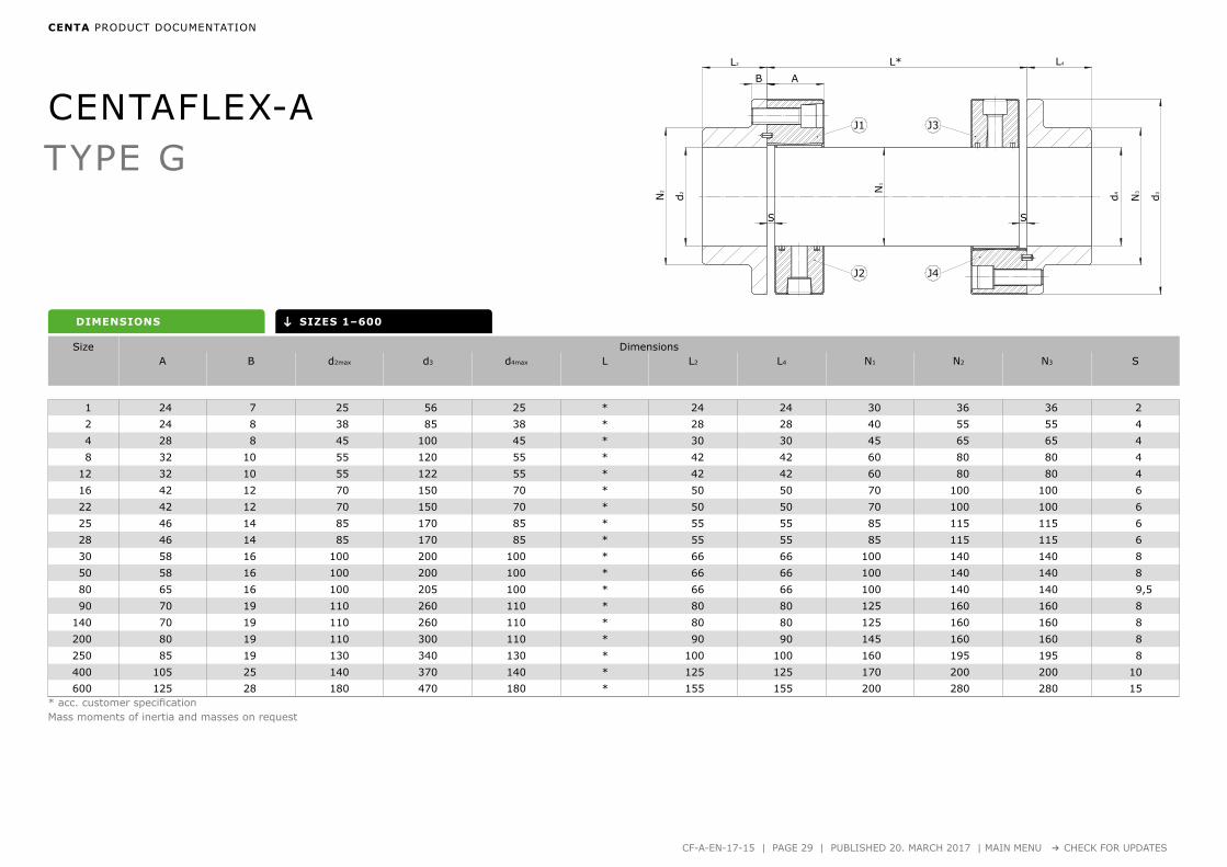
TYPE G
DRIVE SHAFTS
Type G Sizes 1–800 .............................. Page 28
DIMENSIONS
Type G Sizes 1–600 .............................. Page 29
Type GB–GZ Sizes 1–800 .............................. Page 30

CENTA PRODUCT DOCUMENTATION
CF-A-EN-17-15 | PAGE 28 | PUBLISHED 20. MARCH 2017 | MAIN MENU → CHECK FOR UPDATES
CENTAFLEX-A drive shafts in various lengths,
adaptable to the installation requirements if applied
as homokinetic shaft. Also available as carbon-fibre or
glass-fibre designs and with split element. Easy hand-
ling and mountable with minimum effort. Dampens
torsional vibrations and shocks and compensates con-
siderable axial, radial and angular misalignments.
TYPE G
The simplest design type; the centre part is centered
only by the elements. Suitable for short and medium
lengths and for speeds up to approx. 1500 min-1.
TYPE GB/GZ
Accurate, low maintenance centering of the central
part for applications with very high speeds and/or long
shaft length.
CENTAFLEX-ADRIVE SHAFTS
A
L*
B
S S
J1 J3
J2 J4
L2
N3
d4d2N2
L4
d3N
1
↓
CENTAFLEX-A
1 24 7 25 56 25 * 24 24 30 36 36 2
2 24 8 38 85 38 * 28 28 40 55 55 4
4 28 8 45 100 45 * 30 30 45 65 65 4
8 32 10 55 120 55 * 42 42 60 80 80 4
12 32 10 55 122 55 * 42 42 60 80 80 4
16 42 12 70 150 70 * 50 50 70 100 100 6
22 42 12 70 150 70 * 50 50 70 100 100 6
25 46 14 85 170 85 * 55 55 85 115 115 6
28 46 14 85 170 85 * 55 55 85 115 115 6
30 58 16 100 200 100 * 66 66 100 140 140 8
50 58 16 100 200 100 * 66 66 100 140 140 8
80 65 16 100 205 100 * 66 66 100 140 140 9,5
90 70 19 110 260 110 * 80 80 125 160 160 8
140 70 19 110 260 110 * 80 80 125 160 160 8
200 80 19 110 300 110 * 90 90 145 160 160 8
250 85 19 130 340 130 * 100 100 160 195 195 8
400 105 25 140 370 140 * 125 125 170 200 200 10
600 125 28 180 470 180 * 155 155 200 280 280 15
CENTA PRODUCT DOCUMENTATION
CF-A-EN-17-15 | PAGE 29 | PUBLISHED 20. MARCH 2017 | MAIN MENU → CHECK FOR UPDATES
DIMENSIONS
TYPE G
SIZES 1–600
* acc. customer specificationMass moments of inertia and masses on request
Size DimensionsA B d2max d3 d4max L L2 L4 N1 N2 N3 S

B
L*
S S
C A
J1
J2 J4
J3
N2
d2
d4 N3
d3
L4L2
N1
↓
CENTAFLEX-A
1 24 7 5 25 56 25 * 24 24 30 36 36 2
2 24 8 5 38 85 38 * 28 28 40 55 55 4
4 28 8 5 45 100 45 * 30 30 45 65 65 4
8 32 10 5 55 120 55 * 42 42 60 80 80 4
12 32 10 5 55 122 55 * 42 42 60 80 80 4
16 42 12 5 70 150 70 * 50 50 70 100 100 6
22 42 12 5 70 150 70 * 50 50 70 100 100 6
25 46 14 5 85 170 85 * 55 55 85 115 115 6
28 46 14 5 85 170 85 * 55 55 85 115 115 6
30 58 16 5 100 200 100 * 66 66 100 140 140 8
50 58 16 5 100 200 100 * 66 66 100 140 140 8
80 65 16 5 100 205 100 * 66 66 100 140 140 9,5
90 70 19 5 110 260 110 * 80 80 125 160 160 8
140 70 19 5 110 260 110 * 80 80 125 160 160 8
200 80 19 10 110 300 110 * 90 90 145 160 160 8
250 85 19 10 130 340 130 * 100 100 160 195 195 8
400 105 25 10 140 370 140 * 125 125 170 200 200 10
600 125 28 10 180 470 180 * 155 155 200 280 280 15
800 145 28 10 230 545 230 * 165 165 230 325 325 17
CENTA PRODUCT DOCUMENTATION
CF-A-EN-17-15 | PAGE 30 | PUBLISHED 20. MARCH 2017 | MAIN MENU → CHECK FOR UPDATES
DIMENSIONS
TYPE GB/GZ
SIZES 1–800Type GZ
* acc. customer specificationMass moments of inertia and masses on request
Size DimensionsA B C d2max d3 d4max L L2 L4 N1 N2 N3 S

CENTAFLEX-A
CENTA PRODUCT DOCUMENTATION
CF-A-EN-17-15 | PAGE APP-1 | PUBLISHED 20. MARCH 2017 | MAIN MENU → CHECK FOR UPDATES
EXPLANATION OF THE TECHNICAL DATA
This appendix shows all explanations of the technical data for all CENTA products.
the green marked explanations are relevant for this catalog:
1 Size Page APP-2
2 Rubber quality Page APP-2
3 Nominal torque Page APP-2
4 Maximum torque Page APP-2
5 Continuous vibratory torque Page APP-2
6 Permissible power loss Page APP-2
7 Dynamic torsional stiffness Page APP-3
8 Relative damping Page APP-3
9 Speed Page APP-3
10 Permissible axial displacement Page APP-3
11 Axial stiffness Page APP-4
12 Permissible radial displacement Page APP-4
13 Radial stiffness Page APP-4
14 Permissible angular displacement Page APP-4
15 Angular stiffness Page APP-4
Are these technical explanations up to date?
click here for an update check!

CENTAFLEX-A
CENTA PRODUCT DOCUMENTATION
CF-A-EN-17-15 | PAGE APP-2 | PUBLISHED 20. MARCH 2017 | MAIN MENU → CHECK FOR UPDATES
1,0
0,8
0,4
0
0,2
0,6
20 30 40 50 60 70 80 90 °C
StPKV
1 2
3
4 5 61 2
3
4 5 6
EXPLANATION OF THE TECHNICAL DATA
Size
This spontaneously selected figure des-ignates the size of the coupling.
Rubber quality
Shore A
This figure indicates the nominal shore hardness of the elastic element. The nominal value and the effective val-ue may deviate within given tolerance ranges.
Nominal torque
TKN [kNm]
Average torque which can be transmit-ted continuously over the entire speed range.
Maximum torque
[kNm]
TKmax
This is the torque that may occur occasionally and for a short period up to 1.000 times and may not lead to a substantial temperature rise in the rubber element.
In addition the following maximum tor-ques may occur:
∆TKmax =1,8 x TKN
Peak torque range (peak to peak) between maximum and minimum torque, e.g. switch-ing operation.
TKmax1 =1,5 x TKN
Temporary peak torque (e.g. passing through resonances). ΔTKmax or TKmax1 may occur 50.000 times alternating or 100.000 times swelling.
TKmax2 = 4,5 x TKN
Transient torque rating for very rare, extraordinary con-ditions (e.g. short circuits).
Continuous vibratory torque
TKW [kNm]
Amplitude of the continuously permis-sible periodic torque fluctuation with a basic load up to the value TKN.The frequency of the amplitude has no influence on the permissible continuous vibratory torque. Its main influence on the coupling temperature is taken into consideration in the calculation of the power loss.
Operating torque
TBmax [kNm]
The maximum operating torque results of TKN and TKW.
Permissible Power Loss
PKV [kW] or [W]
Damping of vibrations and displacement results in power loss within the rubber element.The permissible power loss is the maxi-mum heat (converted damping work into heat), which the rubber element can dissipate continuously to the envi-ronment (i.e. without time limit) with-out the maximum permissible tempera-ture being exceeded.The given permissible power loss refers to an ambient temperature of 30° C. If the coupling is to be operated at a higher ambient temperature, the tem-perature factor St PKV has to be taken into consideration in the calculation.The coupling can momentarily with-stand an increase of the permissible power loss for a short period under cer-tain operation modes (e.g. misfiring).
PKV30 [kW] or [W]
For a maximum period of 30 minutes the double power loss PKV30 is permis-sible. CENTA keeps record of exact pa-rameters for further operation modes.

CENTAFLEX-A
CENTA PRODUCT DOCUMENTATION
CF-A-EN-17-15 | PAGE APP-3 | PUBLISHED 20. MARCH 2017 | MAIN MENU → CHECK FOR UPDATES
1
0,9
0,8
0,7
20 30 40 50 60 70 80 90
50°Sh60°Sh70°Sh
°C
StCTdyn
1,0
0,8
0,6
0,5
20 30 40 50 60 70 80 90
50°Sh60°Sh70°Sh
°C
0,7
0,9 Stψ
7 8 9 107 8 9 10
EXPLANATION OF THE TECHNICAL DATA
Dynamic torsional stiffness
CTdyn [kNm/rad]
The dynamic torsional stiffness is the relation of the torque to the torsional angle under dynamic loading.The torsional stiffness may be linear or progressive depending on the coupling design and material. The value given for couplings with linear torsional stiffness considers following terms: • Pre-load: 50% of TKN
• Amplitude of vibratory torque: 25% of TKN
• Ambient temperature: 20°C• Frequency: 10 Hz
For couplings with progressive torsional stiffness only the pre-load value changes as stated. The tolerance of the torsional stiffness is ±15% if not stated otherwise.
The following influences need to be considered if the torsional stiffness is required for other operating modes:• Temperature
Higher temperature reduces the dynamic torsional stiffness.Temperature factor St CTdyn has to be taken into consideration in the calculation.
• Frequency of vibrationHigher frequencies increase the torsional stiffness.By experience the dynamic torsional stiffness is 30% higher than the static stiff-ness. CENTA keeps record of exact parameters.
• Amplitude of vibratory torqueHigher amplitudes reduce the torsional stiffness, therefore small amplitudes result in higher dynamic stiffness. CENTA keeps record of exact parameters.
Relative damping
ψ
The relative damping is the relationship of the damping work to the elastic de-formation during a cycle of vibration. The larger this value [ψ], the lower is the increase of the continuous vibratory torque within or close to resonance. The tolerance of the relative damping is ±20%, if not otherwise stated. The relative damping is reduced at high-er temperatures. Temperature factor St Ψ has to be taken into consideration in the calculation.The vibration amplitude and frequency only have marginal effect on the rela-tive damping.
Speed
[min-1]
nmax
The maximum speed of the cou-pling element, which may occur occasionally and for a short pe-riod (e.g. overspeed). The characteristics of mounted parts may require a reduction of the maximum speed (e.g. outer diameter or material of brake discs).
nd
The maximum permissible speed of highly flexible cou-pling elements is normally 90% thereof.
Permissible axial displacement
[mm]
∆Ka
The continuous permissible axial displacement of the coupling.This is the sum of displacement by assembly as well as static and dynamic displacements dur-ing operation.
∆Ka max
The maximum axial displace-ment of the coupling, which may occur occasionally for a short period (e.g. extreme load).The concurrent occurrence of different kinds of displacements is handled in technical docu-ments (displacement diagrams, data sheets, assembly instruc-tions).

CENTAFLEX-A
CENTA PRODUCT DOCUMENTATION
CF-A-EN-17-15 | PAGE APP-4 | PUBLISHED 20. MARCH 2017 | MAIN MENU → CHECK FOR UPDATES
11 12 13 14 1511 12 13 14 15
EXPLANATION OF THE TECHNICAL DATA
Axial stiffness
[kN/mm]
Ca
The axial stiffness determines the axial reaction force on the input and output sides upon axial displacement.
Ca dyn
By experience the dynamic stiff-ness is higher than the static one. The factor depends on the coupling series.
Permissible radial displacement
[mm]
∆Kr
The continuous permissible radi-al displacement of the coupling. This is the sum of displacement by assembly as well as static and dynamic displacements dur-ing operation.The continuous permissible ra-dial displacement depends on the operation speed and may re-quire adjustment (see diagrams Sn of the coupling series).
∆Kr max
The maximum radial displace-ment of the coupling, which may occur occasionally and for a short period without considera-tion of the operation speed (e.g. extreme overload). The concurrent occurrence of different kinds of displacements is handled in technical docu-ments (displacement diagrams, data sheets, assembly instruc-tions).
Radial stiffness
[kN/mm]
Cr
The radial stiffness determines the radial reaction force on the input and output sides upon ra-dial displacement.
Crdyn
By experience the dynamic stiff-ness is higher than the static one. The factor depends on the coupling series.
Permissible angular displacement
[<)°]
∆Kw
The continuous permissible an-gular displacement of the cou-pling. This is the sum of displacement by assembly as well as static and dynamic displacements dur-ing operation.The continuous permissible an-gular displacement depends on the operation speed and may re-quire adjustment (see diagrams Sn of the coupling series).
∆Kw max
The maximum angular displace-ment of the coupling, which may occur occasionally and for a short period without considera-tion of the operation speed (e.g. extreme overload).The concurrent occurrence of different kinds of displacements is handled in technical docu-ments (displacement diagrams, data sheets, assembly instruc-tions).
Angular stiffness
[kNm/°]
Cw
The angular stiffness determines the restoring bending moment on the input and output sides upon angular displacement.
Cwdyn
By experience the dynamic stiff-ness is higher than the static one. The factor depends on the coupling series.
150
0
1000 2000 3000 4000 5000 min-1
75
50
25
125
100
%
Sn

1. This catalog supersedes previous editions.
This catalog shows the extent of our coupling range at the time of printing. This program is still being extended with further siz-es and series. Any changes due to technological progress are reserved.
We reserve the right to amend any dimensions or detail specified or illustrated in this publication without notice and without in-curring any obligation to provide such modification to such couplings previously delivered. Please ask for an application drawing and current data before making a detailed coupling selection.
2. We would like to draw your attention to the need of preventing accidents or injury. No safety guards are included in our supply.
3. TRADEMARKS
CENTA, the CENTA logo, Centacone, CENTADISC, CENTAFIT, Centaflex, CENTALINK, Centalock, Centaloc, Centamax, Centastart, CENTAX and HYFLEX are registered trademarks of CENTA Antriebe Kirschey GmbH in Germany and other countries.
Other product and company names mentioned herein may be trademarks of their respective companies.
4. Torsional responsibility
The responsibility for ensuring the torsional vibration compatibility of the complete drive train, rests with the final assembler. As a component supplier CENTA is not responsible for such calculations, and cannot accept any liability for gear noise/-damage or coupling damage caused by torsional vibrations.
CENTA recommends that a torsional vibration analysis (TVA) is carried out on the complete drive train prior to start up of the ma-chinery. In general torsional vibration analysis can be undertaken by engine manufacturers, consultants or classicfication socie-ties. CENTA can assist with such calculations using broad experience in coupling applications and torsional vibration analysis.
5. Copyright to this technical dokument is held by CENTA Antriebe Kirschey GmbH.
6. The dimensions on the flywheel side of the couplings are based on the specifications given by the purchaser. The responsibility for ensuring dimensional compatibility rests with the assembler of the drive train. CENTA cannot accept liability for interference between the coupling and the flywheel or gearbox or for damage caused by such interference.
7. All technical data in this catalog are according to the metric SI system. All dimensions are in mm. All hub dimensions (N, N1 and N2) may vary, depending on the required finished bore. All dimensions for masses (m), inertias (J) and centres of gravity (S) re-fer to the maximum bore diameter.
CENTAFLEX-A
© 2015 by CENTA Antriebe Kirschey GmbH
Rev. CF-A-EN-17-15

CENTA is the leading producer of flexible couplings for rail, industrial, marine and power generating applications. Worldwide.
WWW.CENTA.INFO/CONTACTCENTA Antriebe
Kirschey GmbH
Bergische Strasse 7
42781 Haan/Germany
+49-2129-912-0 Phone
+49-2129-2790 Fax
www.centa.info
HEAD OFFICE