ceng 491-senior projectumasoft.weebly.com/uploads/1/7/9/0/17900971/sdd.pdf · 5 software design...
TRANSCRIPT
1 Software Design Document
No
ve
mb
er
31
, 2
01
2
CENG 491-SENIOR PROJECT
Software Design Document
3D Simulation and Management of
Video Surveillance System
SURV3D
N.Cihan Boydaş(1678804) A.Emirhan Özdemir(1631290)
Andaç Akarsu(1678630) Ziya Doğramacı(1678853)

2 Software Design Document
CHANGE OF HISTORY
Version Date Changes
1.0 11.31.2012 Document is created for the first time.
1.1 18.01.2013 Used libraries and tools part updated and
changed, each library and tools explained
Human tracking changed as human
detection.(for all part of the sdd, including
diagrams).
It is mentioned that there will be no replay
option to play the recorded video backwards

3 Software Design Document
Table of Contents
1. Introduction...................................................................................................................5
1.1 Problem Definition...... ...........................................................................................5
1.2 Purpose...................................................................................................................5
1.3 Scope........................... ...........................................................................................6
1.4 Overview.................................................................................................................6
1.5 Definitions, Acronyms and Abbreviations...............................................................7
1.6 References..............................................................................................................7
2. System Overview............................................................................................................8
3. Design Considerations....................................................................................................9
3.1 Design Assumptions, Dependencies and Constraints.............................................9
3.1.1 Design Assumptions.....................................................................................9
3.1.2 Design Constraints........................................................................................9
3.1.2.1 Time Constrains................................................................................9
3.1.2.2 Performance Constraints................................................................10
3.2 Design Goals and Guidelines.................................................................................10
4. Data Design..................................................................................................................10
4.1 Data Description....................................................................................................10
4.1.1 User Class...................................................................................................11
4.1.2 Admin Class................................................................................................12
4.1.3 Observer Class............................................................................................13
4.1.4 Camera Class..............................................................................................14
4.1.5 VideoManager Class...................................................................................15
4.2 Data Dictionary.....................................................................................................16
4.2.1 User Class...................................................................................................16
4.2.2 Admin Class................................................................................................17
4.2.3 Observer Class............................................................................................17
4.2.4 Camera Class..............................................................................................17
4.2.5 VideoManager Class...................................................................................19
4.3 Dependency Viewpoint.........................................................................................19
5. System Architecture.....................................................................................................21
5.1 Architectural Design..............................................................................................21
5.2 Decomposition Description...................................................................................22
5.2.1 InputHandler Component..........................................................................23
5.2.1.1 Processing Narrative for InputHandler Component.......................23
5.2.1.2 InputHandler Component Interface Description............................23
5.2.1.3 InputHandler Component Processing Detail..................................23
5.2.1.4 Dynamic Behaviour of InputHandler Component..........................24
5.2.2 OutputHandler Component.......................................................................24

4 Software Design Document
5.2.2.1 Processing Narrative for OutputHandler Component....................24
5.2.2.2 OutputHandler Component Interface Description.........................25
5.2.2.3 OutputHandler Component Processing Detail...............................25
5.2.2.4 Dynamic Behaviour of OutputHandler Component.......................25
5.2.3 Processor Component................................................................................25
5.2.3.1 Processing Narrative for Processor Component............................25
5.2.3.2 Processor Component Interface Description.................................26
5.2.3.3 Processor Component Processing Detail........................................26
5.2.3.4 Dynamic Behaviour of Processor Component................................27
5.2.4 DiscHandler Component............................................................................28
5.2.4.1 Processing Narrative for DiscHandler Component........................28
5.2.4.2 DiscHandler Component Interface Description..............................28
5.2.4.3 DiscHandler Component Processing Detail....................................28
5.2.4.4 Dynamic Behaviour of DiscHandler Component............................28
5.3 Design Rationale...................................................................................................29
6. Human Interface Design...............................................................................................30
6.1 Overview of User Interface...................................................................................30
6.1.1 Authentication(Login) Screen…………………………………………………………………30
6.1.2 Admin Screen…………………………………………………………………………………………30
6.1.3 Observer Screen…………………………………………………………………………………….30
6.1.4 Main Screen…………………………………………………………………………..................31
6.2 Screen Images.......................................................................................................31
6.2.1 Authentication(Login) Screen…………………………………………………………………31
6.2.2 Admin Screen…………………………………………………………………………………………31
6.2.3 Observer Screen…………………………………………………………………………………….33
6.2.4 Main Screen…………………………………………………………………………..................33
7. Libraries and Tools......................................................................................................34
8. Time Planning...............................................................................................................34
8.1 Gannt Chart………………………………………………………………………………………………………35
9. Requirements Matrix……………………………………………………………………………………………….35
10. Conclusion……………………………………………………………………………………………………………….35
5 Software Design Document
1 Introduction
This design report expresses a complete description about 3D Simulation and
Management of Video Surveillance System, sponsored by 3K Information
Technologies. This document includes features, functionalities, specifications and
explanations about the project SURV3D which is a senior design project provided by
Computer Engineering Department of Middle East Technical University.
1.1 Problem Definition
Nowadays security is becoming a major issue in many places like prisons, banks,
military areas, public areas etc. In such kind of areas, security is mainly supplied by
placing surveillance cameras around the place of interest, manually. But these cameras
may have troubles during surveillance due to some blind spots that cannot be covered
by the system. Another problem related with cameras is the fact that today there are
hundreds of different types of cameras with hundreds of different features. This
variation and evolution of cameras cause some inconsistency problems within the
surveillance system.
Problems mentioned above take time and expense to be handled. Such problems may
not be spotted until a dangerous circumstance happens in the critical area where strict
surveillance is required. Therefore it is costly to design and maintain the security
system using cameras manually.
Using a 3D simulation of the area to decide where to put cameras and manage them
using software is a solution to the mentioned problem. With this project we can
foresee design and where to put the cameras by trying out different points so that we
can cover the subject area with minimum number of cameras.
1.2 Purpose
This document describes the design plan for our project and how the requirements
stated in the Software Requirement Specifications will be fulfilled. Requirements in
the SRS document will be translated into structural components. Design concepts and
general design architecture of the project will be explained in a detailed way. Design

6 Software Design Document
issues discussed here are the guidelines we intend to follow; however, they are always
subject to change. The intended audience is prospective software developers and all
users.
1.3 Scope
The scope of this document consists of the design patterns of “SURV3D” project, brief
explanation about the goal, objectives and benefits of the project, constraints,
assumptions, dependencies, detailed data description and data dictionary, system
architecture with its components, user interface and actions of objects, libraries and
tools that will be used.
This project is going to be used as a management infrastructure of concurrent video
surveillance systems. Applying 3D simulation over the subject area that is intended to
keep secure, the system will help deciding where to put cameras and will create a
solution to manage them using software. One can decide where to put cameras by
trying out different coordinates so that the number of cameras used to track the
intended area will be kept minimum. Moreover, system can make it possible to ensure
whether the place is secure using the views of cameras with human detection abilities,
motion detection etc. 3D video fusion method to enrich the visuality of software will
also be used.
1.4 Overview
This document includes design report for “SURV3D”. At the beginning, an overview
of the problem and the product are described. Then, system overview and design
considerations are presented to the audience. After declaring the data design of this
project, system architecture will be clarified explicitly. Then user interface design and
the detailed design of the “SURV3D” are explained clearly. And finally, time planning
of the project will be given.

7 Software Design Document
1.5 Definitions, Acronyms and Abbreviations
ONVIF: open industry forum for the development of a global standard for the
interface of IP-based physical security products.
DTED: Digital Terrain Elevation Data
GDAL: Geospatial Data Abstraction Library
SRS: System requirements specification
SDD: Software Design Document
OSG: Open Scene Graph
OpenCV: Open Source Computer Vision
VTP: Virtual Terrain Project
IHDC: Idiap Human Detection Code
RTSP: Real Time Streaming Protocol
1.6 References
[1] DTED at National Geospatial-Intelligence Agency website
[2] GDAL home page: http://www.gdal.org/
[3] OSG home page: http://www.openscenegraph.org/
[4] ONVIF specifications page: http://www.onvif.org/
[5] IEEE STD 830-1998: IEEE Recommended Practice for Software Requirements
Specifications
8 Software Design Document
[6] OpenCV home page: http://opencv.org/
[7] Virtual Terrain Project home page: http://vterrain.org/
[8] Blob Extraction Library: http://opencv.willowgarage.com/wiki/cvBlobsLib
[9] IdiapHuman Detection Project: http://www.idiap.ch/~odobez/human-
detection/index.html
[10] IEEE Recommended Practice 1016-1998
2 System Overview
"SURV3D" is software which can be used by the registered observers and administrators.
In order to use the system, all users must login with entering their username and
passwords which they got when they signed up to the system. This user information is
held by database. The design will be explained more detailed in design considerations and
data design sections of this document. The administrators and observers will have
different abilities on the system.
Firstly, after logging into the system, administrators can create a 3D world by using
DTED [1] formatted map of desired area or they can just simply add 3D models. After
world creation, they can do some camera modifications. These are limited by placing
cameras, setting camera types, analyzing view frustum and changing camera perspective.
When an administrator tries to log off from the system, he/she can save the 3D world
which he/she was working on.
Secondly, observers will not have the same operation responsibilities. They can open a 3D
world with loading a saved 3D world instead of creating like administrators. When
loading operation is finished, they can interact with 3D environment. For instance they
can navigate in the environment or change camera perspective. Observes can also get live
video from IP cameras or fuse the 3D model with the video. Their last ability on this
environment is human detection. They can toggle human detection and handle human
detection.
9 Software Design Document
3 Design Considerations
3.1 Design Assumptions, Dependencies and Constraints
3.1.1 Design Assumptions
We have designed our project under some assumptions about software and hardware. First of
all, Microsoft Visual C++ 2005 Redistributable package or a higher version should be
installed. In addition, the related DTED [1] formatted maps or 3D models for the area where
surveillance will be conducted is already existed in the system for the administrators to be
able to create the environment. This is not a necessity for the observers. For the hardware
assumptions, the computer, where the software will be used, should be fast enough to handle
receiving video from the cameras. Also the computer should have a good processor to do
fusing video frames and detecting humans to get a better performance. Since the program is
about the security, time efficiency is essential. Therefore, faster the computer is better security
the user can get.
3.1.2Design Constraints
3.1.2.1 Time Constraints
We have mainly two constraints. First one is about receiving video input from cameras. To be
able to make video fusion without excessive amount of latency, we are required to get the
frames as soon as possible. Since, after receiving a frame from a camera we also need to apply
our algorithm for video fusion, we may have some delay for fusing next frame of the video
input. We have assumed that the hardware for transmission of video frames will be good
enough to send video frames and get them in a very short amount of time.
Second one is about 3d video fusion. Since it is a security program, whenever the user tries to
fuse the video frames from the camera into the 3d world, it should take less time to do the
fusion for each frame. Else the user will see delayed output, which is not suitable for a
security program. With less time for fusion, a better surveillance can be done. Therefore we
need to do the coding for fusion part in a very efficient way so that the delay between the
fusions of successive frames should be as less as possible. The same constraints are needed to
be satisfied also for human detection part which is another component of the project, related
with video processing.
3.1.2.2 Performance Constraints

10 Software Design Document
Performance is a critical issue due to the fact that this project is about security and the
surveillance in real time. Mainly, the software will need to do video fusion and human
detection in real time. So, a better performance will lead us to get a better surveillance system,
which means better security. Also the software should be bug-free since any failure in the
software may cause fatal consequences. Therefore, several tests are required to be conducted
to find any failures and analyze the performance of the software so related parts should be
revisited frequently and corrected to overcome these issues.
3.2 Design Goals and Guidelines
During in our work on the project we follow agile software development method to ensure
that we have a well-designed complete work with no failures.
4. Data Design
In this Project, we have mainly five classes namely User, Observer, Admin, Camera and
VideoManager. We are not using database in this project since we don’t have that much data
to use. Instead we will be using XML files and .ini formatted files to hold related data.
The files we will use in this project as follows:
DTED Map: This one has .ini extension. Elevation and texture information for each
tile set is stored in these files.
Users: User related information such as password, username, usertype and userId is
stored in this XML file.
Scenes: The 3D environment information which is modified by an admin will be
stored in XML files.
4.1 Data Description
In this project, we are holding some of the information in XML and .ini files. The rest of the
required information will be received from the user while application is running. We have
mainly five classes that use this information. These classes are explained below in detail.
4.1.1 User Class

11 Software Design Document
This class holds the basic information about users. This information consists of userId,
userName, userType and password of the user. This information will be hold in XML files.
Also chooseMap function is defined in this class to help user to load a DTED [1] formatted
map to create a 3D world. This class will be act as a super class for Admin and Observer
classes.
Figure 1: User Class
Types of attributes:
userId: int
userName: string
userType: int
password: string
cameras: vector<Camera>
Defined Functions:
logIn(userName: string, password: string)
logOff()
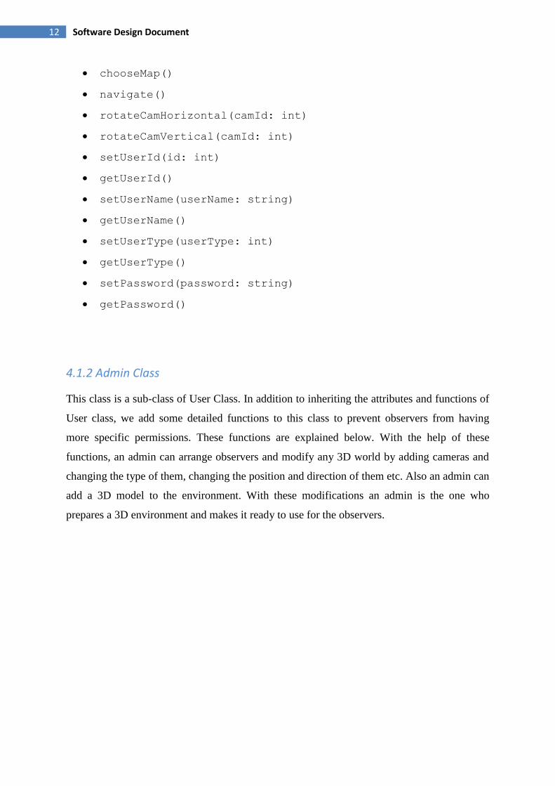
12 Software Design Document
chooseMap()
navigate()
rotateCamHorizontal(camId: int)
rotateCamVertical(camId: int)
setUserId(id: int)
getUserId()
setUserName(userName: string)
getUserName()
setUserType(userType: int)
getUserType()
setPassword(password: string)
getPassword()
4.1.2 Admin Class
This class is a sub-class of User Class. In addition to inheriting the attributes and functions of
User class, we add some detailed functions to this class to prevent observers from having
more specific permissions. These functions are explained below. With the help of these
functions, an admin can arrange observers and modify any 3D world by adding cameras and
changing the type of them, changing the position and direction of them etc. Also an admin can
add a 3D model to the environment. With these modifications an admin is the one who
prepares a 3D environment and makes it ready to use for the observers.

13 Software Design Document
Figure 2: Admin Class
Types of attributes:
elevationMapPath: string
textureMapPath: string
Defined Functions:
addObserver(userId: int, userName: string, password:
string, userType: int)
removeObserver(userId: int)
create3DMap()
save3DMap()
add3DModel()
addCamera()
setElevationMap(selectedElevationMap: string)
getElevationMap()
setTextureMap()

14 Software Design Document
4.1.3 Observer Class
This class is a sub class of User class. Like admin class, the same attributes and functions of
User class is inherited. Mainly, an observer can navigate in the environment while observing.
Also an observer can activate/deactivate humanDetection feature. Apart from this, an observer
can make 3D video fusion using video frames from ip cameras.
Figure 3: Observer Class
Defined Functions:
toggleHumanDetection(status: bool)
4.1.4 Camera Class
Figure 4: Camera Class

15 Software Design Document
Camera class is used for holding information about the cameras in an environment. After an
admin modified the world, the information will be hold in a file which is saved by him/her.
Which means whenever this saved file is loaded, camera related information also will be
loaded.
Types of attributes:
near: float
far: float
fov: float
cameraType: int
cameraId: int
cameraPosition: Coordinate
cameraDirection: Coordinate
cameraIp: string
Defined Functions:
computeViewFrustum()
4.1.5 VideoManager Class
This class handles main functionality of our system. Basically, it can get video input from ip
cameras, fuse this video with 3D environment and detects and tracks human in the video
frames. There will be no replay option in this class to play the recorded video backwards.
Figure 5: VideoManager Class

16 Software Design Document
Types of attributes:
humanDetectionStatus: bool
currentCam: Camera
Defined Functions:
makeVideoFusion()
makeHumanDetection()
getVideoFrame()
4.2 Data Dictionary
4.2.1 User Class
Attributes:
userId: It specifies id number for each user.
userName: It is the name of the user.
userType: This attribute defines the type of the user, that is admin or observer.
password: This attribute is the password for the user to use to log in.
cameras: This attribute holds the information of added camera objects.
Functions:
setUserId: sets the userId with Id.
getUserId: returns an integer which is the userId
setUserName: sets the userName
getUserName: returns a string which is the userName
setUserType: sets the userType
getUserType: returns an integer which is the userType
setPassword: sets the password
getPassword: returns a string which is the password.
chooseMap: loads the XML file which is saved by the admin.

17 Software Design Document
4.2.2 Admin Class
Attributes:
elevationMapPath: This attribute defines the path for the selected elevation map
textureMapPath: This attribute defines the path for the selected texture map
Functions:
addObserver: adds a new observer into the XML file where user information is
being held.
removeObserver: deletes the observer information from the XML file.
create3DWorld: creates a 3D world from a DTED [1] map.
save3DWorld: saves the 3D environment as a XML file to be loaded later by the
observers.
4.2.3 Observer Class
Functions:
toggleHumanDetection: activates/deactivates the human detection feature.
4.2.4 Camera Class
Attributes:
near: This attribute defines near distance of the camera’s viewing frustum.
far: This attribute defines far distance of the camera’s viewing frustum.
fov: This attribute defines the viewing angle in terms of radian.
cameraType: This attribute specifies the camera’s type.
cameraId: This attribute specifies the camera’s id.
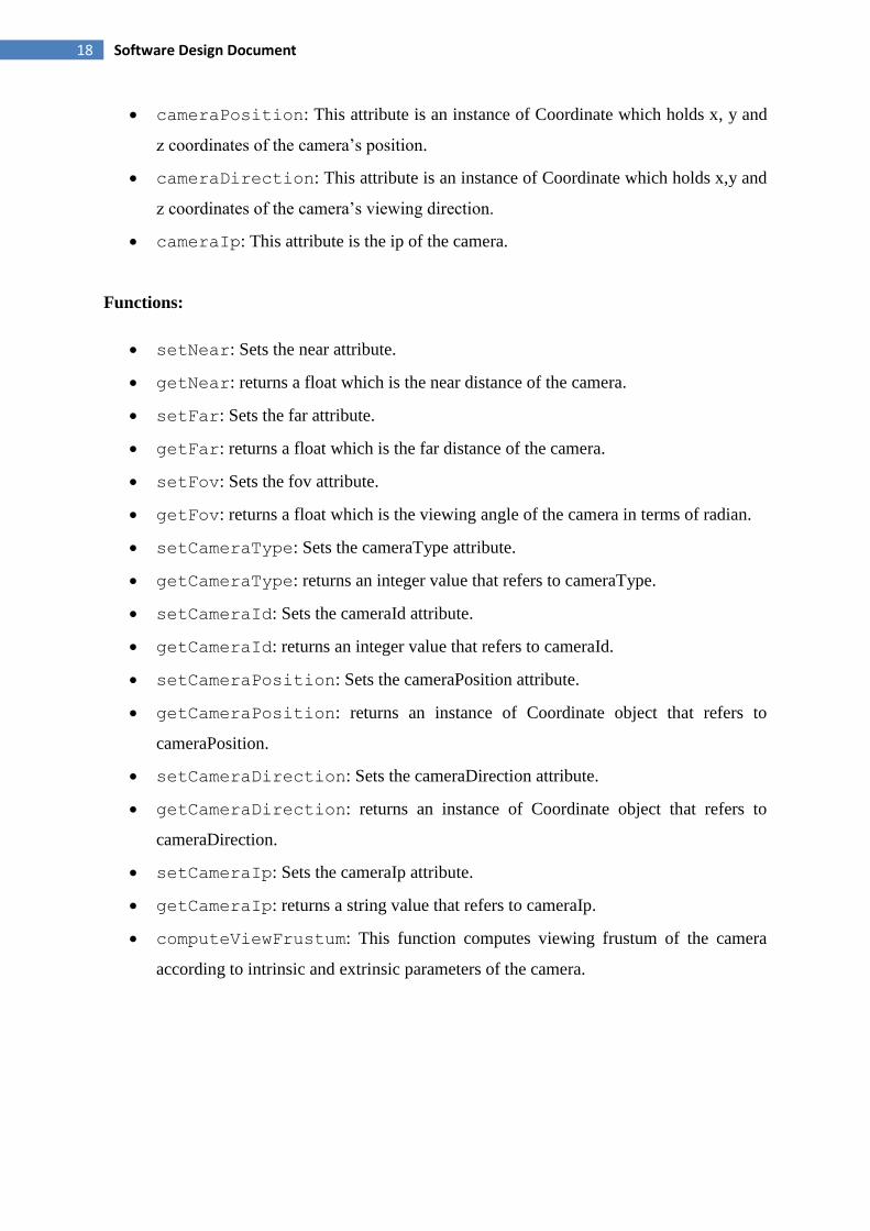
18 Software Design Document
cameraPosition: This attribute is an instance of Coordinate which holds x, y and
z coordinates of the camera’s position.
cameraDirection: This attribute is an instance of Coordinate which holds x,y and
z coordinates of the camera’s viewing direction.
cameraIp: This attribute is the ip of the camera.
Functions:
setNear: Sets the near attribute.
getNear: returns a float which is the near distance of the camera.
setFar: Sets the far attribute.
getFar: returns a float which is the far distance of the camera.
setFov: Sets the fov attribute.
getFov: returns a float which is the viewing angle of the camera in terms of radian.
setCameraType: Sets the cameraType attribute.
getCameraType: returns an integer value that refers to cameraType.
setCameraId: Sets the cameraId attribute.
getCameraId: returns an integer value that refers to cameraId.
setCameraPosition: Sets the cameraPosition attribute.
getCameraPosition: returns an instance of Coordinate object that refers to
cameraPosition.
setCameraDirection: Sets the cameraDirection attribute.
getCameraDirection: returns an instance of Coordinate object that refers to
cameraDirection.
setCameraIp: Sets the cameraIp attribute.
getCameraIp: returns a string value that refers to cameraIp.
computeViewFrustum: This function computes viewing frustum of the camera
according to intrinsic and extrinsic parameters of the camera.
19 Software Design Document
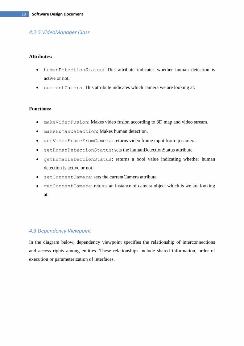
4.2.5 VideoManager Class
Attributes:
humanDetectionStatus: This attribute indicates whether human detection is
active or not.
currentCamera: This attribute indicates which camera we are looking at.
Functions:
makeVideoFusion: Makes video fusion according to 3D map and video stream.
makeHumanDetection: Makes human detection.
getVideoFrameFromCamera: returns video frame input from ip camera.
setHumanDetectionStatus: sets the humanDetectionStatus attribute.
getHumanDetectionStatus: returns a bool value indicating whether human
detection is active or not.
setCurrentCamera: sets the currentCamera attribute.
getCurrentCamera: returns an instance of camera object which is we are looking
at.
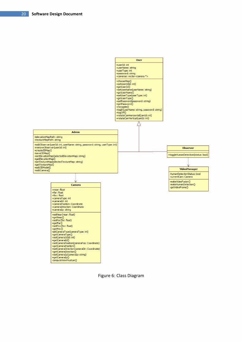
4.3 Dependency Viewpoint
In the diagram below, dependency viewpoint specifies the relationship of interconnections
and access rights among entities. These relationships include shared information, order of
execution or parameterization of interfaces.
20 Software Design Document
Figure 6: Class Diagram
21 Software Design Document
5 System Architecture
5.1 Architectural Design
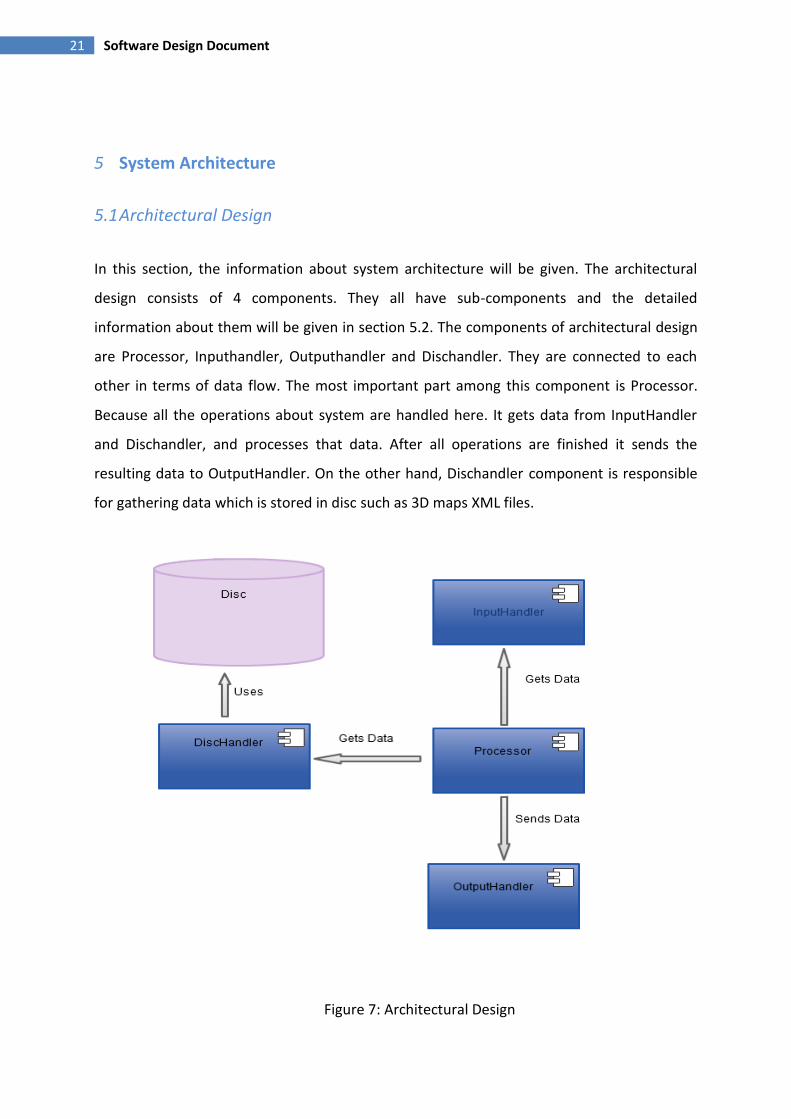
In this section, the information about system architecture will be given. The architectural
design consists of 4 components. They all have sub-components and the detailed
information about them will be given in section 5.2. The components of architectural design
are Processor, Inputhandler, Outputhandler and Dischandler. They are connected to each
other in terms of data flow. The most important part among this component is Processor.
Because all the operations about system are handled here. It gets data from InputHandler
and Dischandler, and processes that data. After all operations are finished it sends the
resulting data to OutputHandler. On the other hand, Dischandler component is responsible
for gathering data which is stored in disc such as 3D maps XML files.
Figure 7: Architectural Design

22 Software Design Document
5.2 Decomposition Description
This section describes the main components of the project. As stated previously, four
components are present namely; Inputhandler, Outputhandler, DiscHandler and Processor.
There will be detailed information about these components in the following sections.

23 Software Design Document
Figure 7: Sequence Diagram
5.2.1 InputHandler Component
5.2.1.1 Processing Narrative for Inputhandler Component
Main responsibility of this component is to receive messages from outside world and deliver
them to Processer component. This component is placed in between the environment and
Processor component. It directs the requests coming from users to Processor.
5.2.1.2 InputHandler Component Interface Description
This module gets the input from users for the whole system. By means of InputHandler
component, user can interact with Processor component. Therefore he or she can get the
expected result from OutputHandler network component and view on the screen. The data is
sent to InputHandler component can be either a request like changing camera perspective or
login information. As a result, users and the environment are the input interface of
InputHandler component, while Processor component is the output interface.
5.2.1.3 InputHandler Component Processing Detail
InputHandler component gets the requests from users. It can be just a display action, register
request or 3D map navigation. There will be two subcomponents in this network component.
It strictly depends on the information in login operation when the user enters to system. Two
subcomponents are Admin and Observer.
If the system is in InputHandler component mode;
•InputHandler’s subcomponents wait an action from users or administrators.
• Related data is taken.
•Data is sent to Processor component.

24 Software Design Document
5.2.1.4 Dynamic Behavior of InputHandler Component
InputHandler component interacts with only Processor component and users. Therefore the
behavior of InputHandler network component can be explained as this:
•User --- InputHandler Component --- Processor
•Request ==> Send Request Message
Figure 8: Sequence Diagram for InputHandler Network Component
5.2.2 OutputHandler Component
5.2.2.1 Processing Narrative for OutputHandler Component
This component is placed between Processor component and the environment. It is used to
control the outputs sent from Processor to users.

25 Software Design Document
5.2.2.2 OutputHandler Component Interface Description
OutputHandler gets the data from Processor and sends to environment. Therefore, input
interface for OutputHandler component is Processor, while output interface is environment.
5.2.2.3 OutputHandler Component Processing Detail
OutputHandler network component’s processing detail is as follows:
• OutputHandler waits for Processor’s message.
• Processor sends the message with data that is going to be displayed.
• OutputHandler shows the data in a proper way to users.
5.2.2.4 Dynamic Behavior of OutputHandler Component
The behavior of OutputHandler network component has been showed below.
• Processor --- OutputHandler Component --- User
• Respond Request Message ==>Translate Message
Figure 9: Sequence Diagram for OutputHandler Component
5.2.3 Processor Component
5.2.3.1 Processing Narrative for Processor Component
Processor is the most important component of the system since it operates on all the main
jobs. All the main functions of the system are processed in this component. Such as;
comparing the login data with stored ones, processing the given 3D models, handling maps
26 Software Design Document
and preparing what is going to be displayed are some jobs that are handled by Processor
component. On the other hand, Processor component works with DiscHandler, InputHandler
and OutputHandler. It is responsible for processing data from InputHandler and DiscHandler
and sending it to OutputHandler.
5.2.3.2 Processor Component Interface Description
The Processor component interacts with all other three components while it only requests data
from the DiscHandler component. However, InputHandler component delivers the requests
from users to Processor. Processor responds these requests via OutputHandler. Therefore,
InputHandler and DiscHandler components are input interfaces of this component. On the
other hand, OutputHandler is the output interface of Processor component.
5.2.3.3 Processor Component Processing Detail
Processor is the component where all the main data operations are done. These operations are
such as adding 3D models, using maps, handling cameras, login and register checking.
Because these operations are in different categories, there should be different subcomponents
in Processor component.
First of all, since the system has two different user types, there should be a login operation. To
handle this, there should be a subcomponent related to user types in Processor component.
When user enters his/her login information, InputHandler component will take this
information and deliver to Processor. This subcomponent of Processor will check whether it
matches with XML files. If the login information is correct, it decides if the user is
administrator or observer. Then it will direct the user to related screen according to its type.
Other subcomponent is related to visual operations. It handles visual operations such as 3D
maps and cameras. If user wants to add 3D maps, DiscHandler subcomponent sends the
information about related map to Processor component. Then, Processor makes that
information ready to be displayed and sends to OutputHandler.
Processing details of Processor component can be seen as follows:
• InputHandler sends message to Processor component.
• Processor sends a requirement message for data to DiscHandler component.

27 Software Design Document
• DiscHandler sends wanted data to Processor component.
• Processor operates on data.
• Processor sends the result of operations to OutputHandler component.
5.2.3.4 Dynamic Behavior of Processor Component
The dynamic behavior of the management component is shown below;
Figure 10: Sequence Diagram for Processor Component
28 Software Design Document
5.2.4 DiscHandler Component
5.2.4.1 Processing Narrative for DiscHandler Component
DiscHandler has an interaction with Disc where all XML files and DTED [1] maps are stored.
When any data is required, Processor interacts with DiscHandler component. DiscHandler
gets the related data from disc and sends it to Processor. The derived information is
processed in Processor component.
5.2.4.2 DiscHandler Component Interface Description
DiscHandler gets the desired information from the disc. Therefore, disc should be a
subcomponent of DiscHandler instead of being an interface.
since the information in the disc is send to Processor using DiscHandler component,
Processor is output interface for DiscHandler component.,
Also, disc gets information to be stored from Processor via DiscHandler, Processor is input
interface for DiscHandler component, too.
5.2.4.3 DiscHandler Component Processing Detail
•Processor sends a message for data requirement.
•DiscHandler gets the message
•DiscHandler sends the data information to Processor component.
5.2.4.4 Dynamic Behavior of DiscHandler Component
The dynamic behavior of the DiscHandler component is shown in Figure 11.

29 Software Design Document
Figure 11: Sequence Diagram for DiscHandler Component
5.3 Design Rationale
Our project consists of four components. Each of them handles different purposes with their
own subcomponents. Most important component is Processor since it handles all the main
functions in the system and it interacts with all other three components. While Processor
component gets the data request message from user via InputHandler, it responds the
message via OutputHandler and user gets the desired information on his/her screen. On the
other hand, Processor is in interaction with DiscHandler component to get some data which
is stored in disc. As already mentioned, our system has four components. Also, these
components have some subcomponents. Since it is really important to group and facilitate
jobs, this fragmentation into subcomponents became very useful. On the other hand, it was
important that it would be easier if components and subcomponents are not complicated.
Therefore, importance of fragmentation arises again.
The system also interacts with environment via InputHandler and OutputHandler. Users can
give inputs and they can see the output. These two components can be seen as one since
they are among users and Processor. We implement these as two different components to
make system clearer and simpler.
30 Software Design Document
Some information should have been saved such as login info and maps. Instead of using a
database XML files are used. DiscHandler component is the module that reaches those XML
files.
6 HUMAN INTERFACE DESIGN
6.1 Overview of User Interface
Product will have a graphical user interface which facilitates user’s utilization of program.
GUI will mainly have four screens as follows;
6.1.1 Authentication (Login) Screen
Trying to use the system, users will be demanded to get authorized from the system. In order
to display the interface corresponding to his/her role (admin or observer), users must be
authenticated from the system. In this screen user will write his/her user name and password
then login the system. Depending on the user type next phase will be decided.
6.1.2 Admin Screen
If the user has admin authentication, user will see this screen. In this interface admin can add
new observers and decide on their authentication. Also, 3D environment can be created in this
screen. Moreover, 3D models can be added on this screen. After the creation of the 3D world,
finishes, admin can choose camera types and add these cameras to the 3D world to set up
view frustum. When all the executed operations are done, admin can save the session and
logout from the system.
6.1.3 Observer Screen
If the user has observer authentication, user will see this screen. In this interface observer first
loads a 3D world. Observer can navigate in the 3D world freely and change camera
perspectives while viewing the environment with fused video from cameras. Also observer
can toggle human detection feature and can detect human intrusion to the system.

31 Software Design Document
6.1.4 Main Screen
Both Observer and admin users can interact with this screen and use the application according
to their authentication.
6.2 Screen Images
6.2.1 Authentication (Login) Screen
Figure 12: Authentication (Login) Screen
6.2.2 Admin Screen
Figure 13: Admin Screen
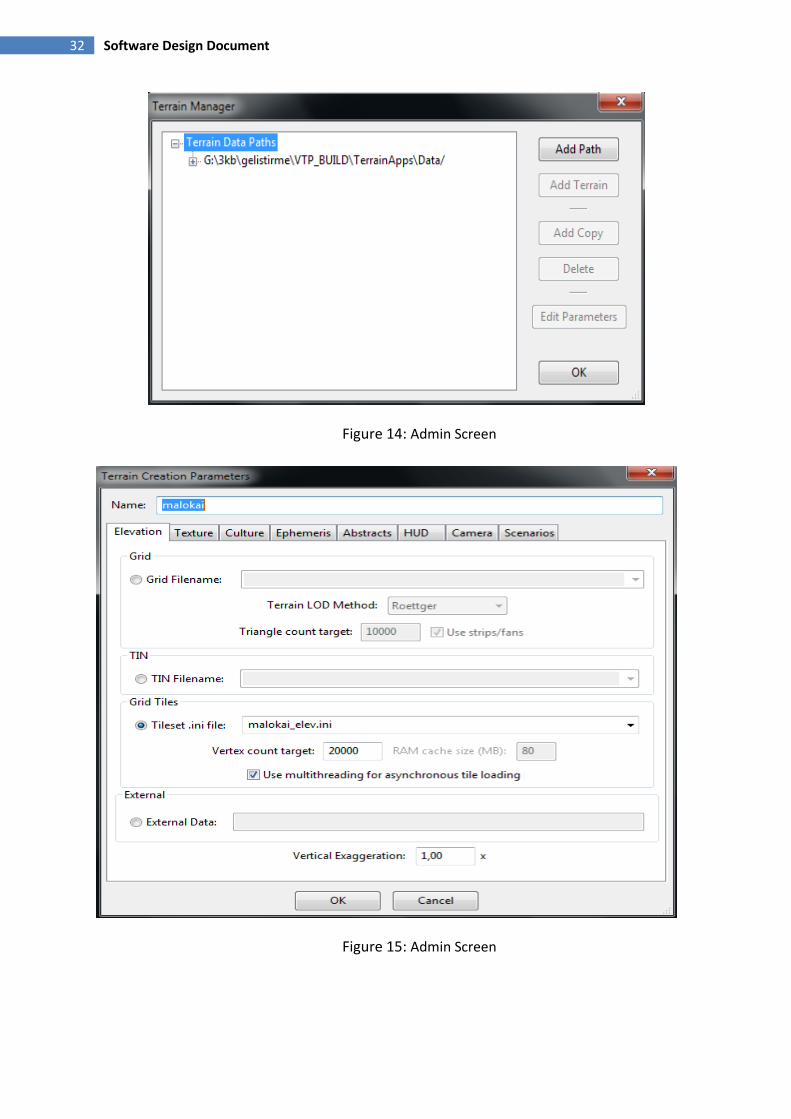
32 Software Design Document
Figure 14: Admin Screen
Figure 15: Admin Screen

33 Software Design Document
6.2.3 Observer Screen
Figure 16: Observer Screen
6.2.4 Main Screen
Figure 17: Main Screen

34 Software Design Document
7 Libraries and Tools
The software will be designed on C++ using Visual Studio 2010 on Windows x86 operating
system.
The followings are the tools and libraries that we are take advantage of while maintaining the
project:
VTP:
VTP[7] is an open source project written with C++. It is designed to foster the creation of
tools for easily constructing any part of the real world in interactive, 3D digital form. It is
composed of two different projects: vtBuilder and Enviro. vtBuilder converts the given DTED
maps(elevation map and texture map) into tilesets so that Enviro can use them to create the
desired 3D environment. Enviro uses the tilesets that are created by vtBuilder to render the 3D
environment and it also provides navigation inside the created 3D environment. It also has
several features to add vehicles, animals, trees, buildings etc. into the environment but we are
not interested with those features.
vtBuilder uses GDAL[2] library to convert the given maps into tilesets.
Enviro uses OSG library as its core to handle the navigation issue.
For the further information u can refer to the website given in references section.
Since VTP[7] provides the creation of the 3D environment and navigation inside the created
3D environment we are using it as a core inside our project. The other features of the project
will be integrated onto this core.
IHDC:
IHDC[9] designed by the research group Idiap. It is an open source project written with C++.
It is composed of two parts. First part is background subtraction. For this part a background
subtraction algorithm is used to subtract each frame from the background. For the details of
the algorithm u can refer to the article written by Jian Yao and Jean-Marc Odobez, in the website
given in references section. The second part is human detection. The details of the algorithm

35 Software Design Document
can be found in the article written by Jian Yao and Jean-Marc Odobez, in the website given in the
references section also.
The project is based on OpenCV[6] library. All the operations are handled by using built in
functions of OpenCV[6]. The project also uses cvBlobsLib[8] library to make blob detection.
For the human detection part we are planning to use this project after making some
modifications on it.
RTSPClient:
It is a project written in C++. It is an open source project. We created this project by
combining the code segments that we have found on the internet. It is now working for only
one single camera. This project takes an ip address of an rtsp camera to record the stream
8 Time Planning
Figure 18: Estimation Diagram
8.1 Gannt Chart

36 Software Design Document
Figure 19: Gannt Chart
9 Requirements Matrix
Functional requirements in SRS are given below with their document references. Also, system
components that satisfy these functional requirements are given.
Use Cases Components
2.2.1.1 Login User class- Login
2.2.1.2 Create 3D World Admin class-create3DWorld
2.2.1.3 Set Camera Type Camera class-setCameraType
2.2.1.4 Add Camera Admin class-addCamera
2.2.1.5 Analyze Camera Camera class-computeViewFrustum
2.2.1.6 Add 3D Model Admin class-add3DModel
2.2.1.7 Save 3D World Admin class-save3DWorld
2.2.1.8 Obtain Live Video VideoManager class-getVideoFrame
2.2.1.9 3D Video Fusion VideoManager class-makeVideoFusion
2.2.1.10 Navigate in 3D World User class-navigate

37 Software Design Document
2.2.1.11 Toggle Human Detection Observer class-toggleHumanDetection
2.2.1.12 Change Camera Perspective User class-rotateCamVertical and
rotateCamHorizontal
10 Conclusion
In conclusion, this report is the Software Design Document of the SURV3D project. It is
aimed to show connections between the different parts of the project and to give software
design specifications. This report was prepared according to IEEE Recommended Practice
1016-1998[10].
In the first part, there are problems that are tried to be solved, purpose and scope of the
project. In the second part, system overview is given. Third part includes all the design
considerations. In addition to all details about data design, class diagrams are given in the
fourth part. In the fifth part of the document, the information about system architecture is
given. In the sixth part, interfaces of the system are covered from the users’ perspective. In the
seventh part, libraries and tools that are going to be used are given. Time planning of the
project and the Gannt Chart is in the eighth part.