cem – introduction to primary cementing
TRANSCRIPT

CEM – Introduction to PrimaryCementingReference: 4223307Version: 1.02Release Date: 17-Sep-2008EDMS UID: 274553740Produced: 17-Sep-2008 13:44:17Owner: SRPC Doc/TBT CementingAuthor: SRPC Doc/TBT Cementing
Private
Copyright © 2008 Schlumberger, Unpublished Work. All rights reserved.
Primary Cementing - Introduction / Legal Information
Legal Information
Copyright © 2008 Schlumberger, Unpublished Work. All rights reserved.
This work contains the confidential and proprietary trade secrets of Schlumbergerand may not be copied or stored in an information retrieval system, transferred,used, distributed, translated or retransmitted in any form or by any means,electronic or mechanical, in whole or in part, without the express writtenpermission of the copyright owner.
Trademarks & Service marks
Schlumberger, the Schlumberger logotype, and other words or symbols usedto identify the products and services described herein are either trademarks,trade names or service marks of Schlumberger and its licensors, or are theproperty of their respective owners. These marks may not be copied, imitatedor used, in whole or in part, without the express prior written permission ofSchlumberger. In addition, covers, page headers, custom graphics, icons, andother design elements may be service marks, trademarks, and/or trade dressof Schlumberger, and may not be copied, imitated, or used, in whole or in part,without the express prior written permission of Schlumberger.
A complete list of Schlumberger marks may be viewed at the SchlumbergerOilfield Services Marks page: http://markslist.slb.com
Marks of Schlumberger include but may not be limited to CemCADE.
List of Trademark
Term Definition
CemCADE Mark of Schlumberger
PrivateCopyright © 2008 Schlumberger, Unpublished Work. All rights reserved.S
RPC
Doc/TBT
Cementing\SRPCDoc/TBTCementing\4223307\1.02\ReleaseDate:17-Sep-2008\EDMSUID:274553740\Produced:17-Sep-200813:44:17

Primary Cementing - Introduction / Document Control
Document ControlOwner: SRPC Doc/TBT Cementing
Author: SRPC Doc/TBT Cementing
Reviewer: SRPC Doc/TBT Cementing
Approver: SRPC Doc/TBT Cementing
Contact InformationName: SRPC Doc/TBT CementingAddress: SRPC
1 rue Becquerel92140 CLAMARTFRANCE
Phone: 33 1 45 37 20 00LDAP Alias: SRPCDoc-TBTCementing
Revision HistoryRev Effective Date Description Prepared by
1.0 01-Sep-1999 Last Technical Update SRPC Doc/TBTCementing
1.01 18-Jul-2006 EDMS conversion SRPC Doc/TBTCementing
1.02 17-Sep-2008 New references following newInTouch publication.
SRPC Doc/TBTCementing
PrivateCopyright © 2008 Schlumberger, Unpublished Work. All rights reserved.S
RPC
Doc/TBT
Cementing\SRPC
Doc/TBT
Cementing\4223307\1.02\ReleaseDate:17-Sep-2008\EDMSUID:274553740\Produced:17-Sep-200813:44:17

iv Primary Cementing - Introduction / Table of Contents iv
Table of Contents
1 Introduction ______________________________________________________ 11.1 Purpose of different cemented strings ___________________________ 2
1.1.1 Conductor pipe _____________________________________________ 21.1.2 Surface casing _____________________________________________ 31.1.3 Intermediate casing _________________________________________ 31.1.4 Production casing __________________________________________ 31.1.5 Liners _____________________________________________________ 31.1.6 Tie-back casing ____________________________________________ 41.2 Slurry placement _______________________________________________ 5
1.2.1 Successful primary cementing _______________________________ 8
2 Design __________________________________________________________ 10
3 Execution _______________________________________________________ 11
4 Evaluation ______________________________________________________ 11
5 Organization of primary cementing information _________________ 12
List of Acronym _________________________________________________ 13
PrivateCopyright © 2008 Schlumberger, Unpublished Work. All rights reserved.SR
PCDoc/TBT
Cementing\SRPC
Doc/TBT
Cementing\4223307\1.02\ReleaseDate:17-Sep-2008\EDMSUID:274553740\Produced:17-Sep-200813:44:17

1 Primary Cementing - Introduction / Introduction 1
1 IntroductionPrimary cementing is the process of placing cement slurries in the annular spacebetween the casing and the borehole or previous casing or both. In principle, thetechnique for this placement is the same regardless of the casing size, purpose,type, etc.: slurry is pumped down the string to be cemented, exits the bottomthrough the shoe and, with a preflush normally pumped ahead of it, displacesthe mud while moving up the annulus.
Cemented strings include conductor pipe, surface casing, intermediate casing,production casing and liners. The downhole equipment associated with cementplacement for each casing/pipe type is the main difference in the cementingtechniques. Exceptions are:
• stage cementing where the cement column is placed in the annulus in”stages” using a stage collar, because a downhole formation is unable tosupport the hydrostatic pressure exerted by a long column of cement,
• stab-in cementing where the slurry is pumped down drillpipe to the casingbottom using stab-in equipment,
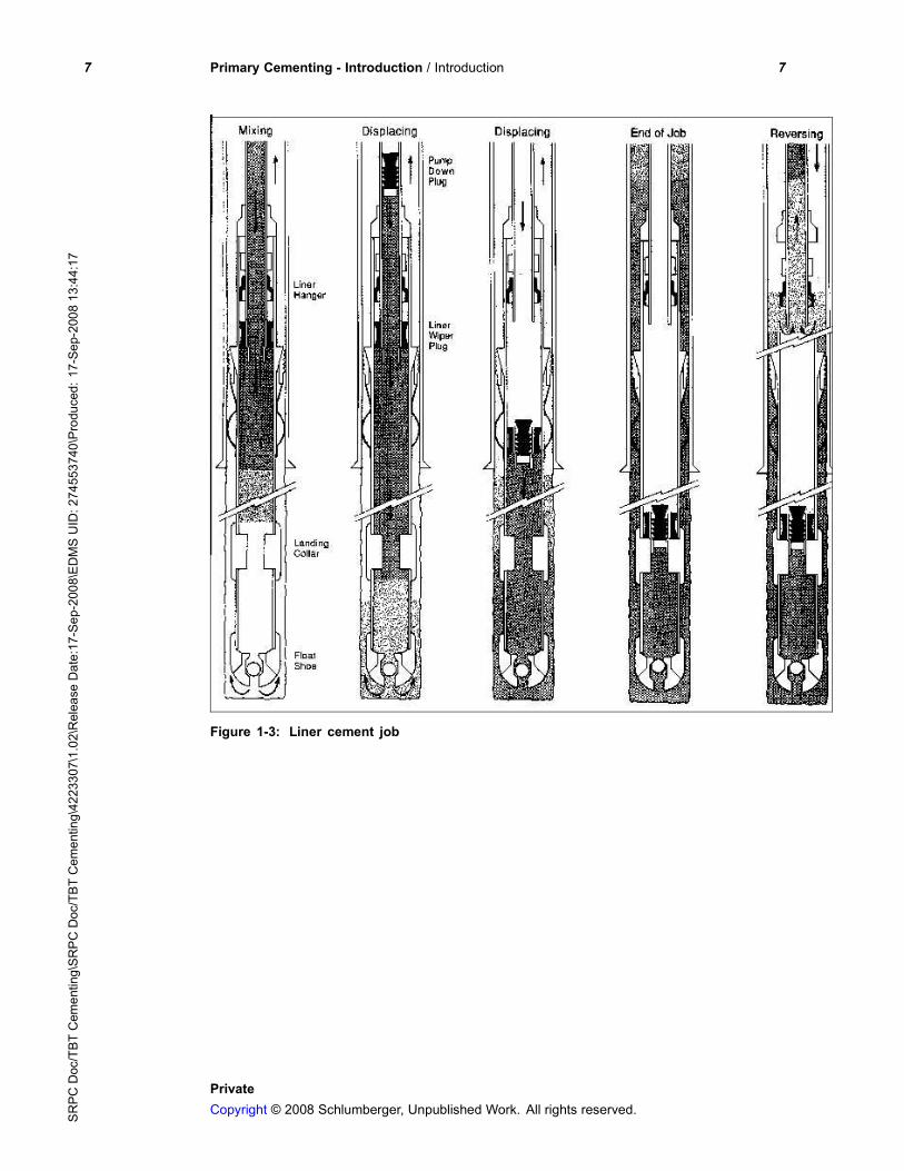
• liner cementing where the slurry reaches the shoe by traveling first throughdrillpipe, next through the liner hanger and then through the liner itself; finalcement placement is across the liner interval only (with some cement leftimmediately above the liner).
Refer to CEM Equipment Requirements, InTouch content #4223307# and CEMEexcution Procedures, InTouch content #4223307# for the description andapplication of these techniques.
The objectives of a primary cement job vary depending on the application. Theycan be any combination of the following:
• prevent the migration of formation fluids or gases in the wellbore annulus(zonal isolation),
• anchor and support the casing string,
• protect the casing string against corrosion,
• confine stimulation treatments to target intervals (zonal isolation),
• meet government regulations,
• provide customer value cost effectively.
PrivateCopyright © 2008 Schlumberger, Unpublished Work. All rights reserved.S
RPC
Doc/TBT
Cementing\SRPCDoc/TBTCementing\4223307\1.02\ReleaseDate:17-Sep-2008\EDMSUID:274553740\Produced:17-Sep-200813:44:17

2 Primary Cementing - Introduction / Introduction 2
These objectives are met when the cement job achieves:
• effective mud removal, which results in a complete cement sheath in theannulus,
• a hydraulic seal, which provides zonal isolation,
• the top of cement (TOC) as per design.
1.1 Purpose of different cemented stringsThe selection of a conductor pipe, casing strings or liners for a new wellapplication is based on the well conditions, and on operational, environmentaland safety requirements each string meets once it is cemented in place. Thefinal number of casings and liners and their configuration are influenced by thepore versus fracture pressure of the formations and the physical casing and linerlimitations versus the anticipated or known well conditions.
Casing strings and conductor pipe extend from the surface to the total depth andare partially cemented (from casing total depth to a selected depth part way upthe hole) or completely cemented (from the casing total depth to the surface).
Once completely cemented in place, liners extend from the total depth to a depthranging from 50 to 500 ft above the setting depth of the previous casing or liner(except for liners used to replace damaged production casing). The top of theliner is always well below the surface.
1.1.1 Conductor pipeA conductor pipe is only used when required. During drilling, a conductor pipe:
• protects shallow sands from contamination by drilling mud,
• helps prevent washouts of unconsolidated beds near the surface,
• provides a channel to raise the circulating fluid to the surface mud system.
A conductor pipe allows the attachment of a blowout preventer (BOP) shouldwell security be a concern during drilling to the surface casing depth. It providescorrosion protection of subsequent casing strings and may be used to supportsome of the wellhead load when the ground support may be inadequate.
PrivateCopyright © 2008 Schlumberger, Unpublished Work. All rights reserved.SR
PCDoc/TBT
Cementing\SRPC
Doc/TBT
Cementing\4223307\1.02\ReleaseDate:17-Sep-2008\EDMSUID:274553740\Produced:17-Sep-200813:44:17

3 Primary Cementing - Introduction / Introduction 3
1.1.2 Surface casingThe surface casing seals off unconsolidated formations and aquifers at relativelyshallow depths and prevents the contamination of fresh groundwater. Thesurface casing supports:
• the BOP throughout most of the drilling operation,
• part of the suspended weight of future casing strings run into the well,
• the well completion equipment (e.g., wellhead, tubing, etc.).
Government regulations may stipulate the minimum requirements of the surfacecasing.
1.1.3 Intermediate casingAn intermediate casing (see Figure 1-1) is used to:
• maintain the borehole integrity as greater drilling depths are encountered,
• seal off weak zones before drilling into high-pressure zones, for which ahigher density drilling mud is required,
• eliminate drilling fluid contamination by salt or anhydrite formations,
• protect the borehole in deviated sections,
• seal off nonproductive, high-pressure zones above the zone of interest.
1.1.4 Production casingThe placement and cementation of the production casing is the principalobjective when drilling a well. The production casing completely isolates thereservoir from undesirable fluids in the zones penetrated by the wellbore. It alsoserves as a protective housing for completion equipment used in the wellbore.
1.1.5 LinersLiners have several different applications and their types are classifiedaccordingly (see Figure 1-1).
• A production liner is used instead of production casing or is used to isolateexisting production casing that is damaged. For the latter case, the liner iscemented inside of the damaged production casing (not shown).
PrivateCopyright © 2008 Schlumberger, Unpublished Work. All rights reserved.S
RPC
Doc/TBT
Cementing\SRPCDoc/TBTCementing\4223307\1.02\ReleaseDate:17-Sep-2008\EDMSUID:274553740\Produced:17-Sep-200813:44:17
4 Primary Cementing - Introduction / Introduction 4
• A drilling or intermediate liner cases off and isolates thief zones, highlyoverpressured zones, sloughing shales or plastic formations so that drillingmay be continued.
• A tie-back stub liner is generally used to isolate damaged, worn, corrodedor deliberately perforated casing above the existing liner, and to provide thewellbore with additional protection against corrosion or pressure.
1.1.6 Tie-back casingTie-back casing is normally used during production to repair damaged casingabove a liner. It is similar to a tie-back stub liner, but it extends to the surface(see Figure 1-1).
PrivateCopyright © 2008 Schlumberger, Unpublished Work. All rights reserved.SR
PCDoc/TBT
Cementing\SRPC
Doc/TBT
Cementing\4223307\1.02\ReleaseDate:17-Sep-2008\EDMSUID:274553740\Produced:17-Sep-200813:44:17

5 Primary Cementing - Introduction / Introduction 5
Figure 1-1: Liner and casing configurations
1.2 Slurry placementThe two techniques for slurry placement are the single-stage and multiple-stagemethods.
The single-stage method achieves complete slurry placement in one step orstage.
PrivateCopyright © 2008 Schlumberger, Unpublished Work. All rights reserved.S
RPC
Doc/TBT
Cementing\SRPCDoc/TBTCementing\4223307\1.02\ReleaseDate:17-Sep-2008\EDMSUID:274553740\Produced:17-Sep-200813:44:17

6 Primary Cementing - Introduction / Introduction 6
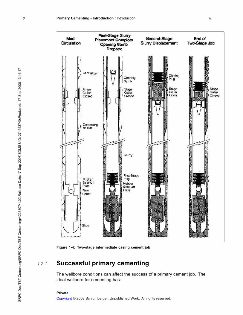
The multiple-stage method achieves complete slurry placement in two or threestages. The different phases of a regular two-stage intermediate casing cementjob. The phases are:
1. The first-stage slurry is placed as if a single-stage cement job was beingperformed.
2. An opening bomb is dropped, which seats in the lower portion of the stagecollar; once the bomb has seated, internal pressure is applied until the stagecollar opens and circulation is established.
3. The second-stage slurry is placed as if a single-stage cement job was beingperformed; the closing plug seats in the upper portion of the stage collar, andby pressuring up on this plug, the stage collar closes, which ends the job.
Primary cement jobs (casing or liner) require casing hardware for practical jobexecution and successful results. Casing hardware is fully described in CEMEquipment Requirements, InTouch content #4223307#.
Figure 1-2: Single-stage, casing cement job
PrivateCopyright © 2008 Schlumberger, Unpublished Work. All rights reserved.SR
PCDoc/TBT
Cementing\SRPC
Doc/TBT
Cementing\4223307\1.02\ReleaseDate:17-Sep-2008\EDMSUID:274553740\Produced:17-Sep-200813:44:17
7 Primary Cementing - Introduction / Introduction 7
Figure 1-3: Liner cement job
PrivateCopyright © 2008 Schlumberger, Unpublished Work. All rights reserved.S
RPC
Doc/TBT
Cementing\SRPCDoc/TBTCementing\4223307\1.02\ReleaseDate:17-Sep-2008\EDMSUID:274553740\Produced:17-Sep-200813:44:17
8 Primary Cementing - Introduction / Introduction 8
Figure 1-4: Two-stage intermediate casing cement job
1.2.1 Successful primary cementingThe wellbore conditions can affect the success of a primary cement job. Theideal wellbore for cementing has:
PrivateCopyright © 2008 Schlumberger, Unpublished Work. All rights reserved.SR
PCDoc/TBT
Cementing\SRPC
Doc/TBT
Cementing\4223307\1.02\ReleaseDate:17-Sep-2008\EDMSUID:274553740\Produced:17-Sep-200813:44:17

9 Primary Cementing - Introduction / Introduction 9
• a stabilized wellbore (e.g., no sloughing, thin and impermeable mud filtercake, and no losses or inflow),
• a uniform wellbore geometry (e.g., in gauge and as uniform as possible,no excessive doglegs or washouts),
• conditioned mud (e.g.; minimum viscosity, yield point, gel strength anddensity; degassed),
• accurate wellbore data (e.g., bottomhole static temperature [BHST],bottomhole circulating temperature [BHCT], pore pressures, fracturegradients, hole caliper, well trajectory, etc.),
• a centered casing with a 1.5-in annular gap, which prevents slurrydehydration and bridging.
Primary cementing is one of the most critical stages during the drilling andcompletion phases of a well, and it has only one chance for success. Asuccessful primary cement job:
• meets the chemical and physical requirements of slurry performance anddisplacement mechanics,
• performs the job design which has practical procedures for field execution(e.g., availability and capacity of equipment, composition of cement andmud removal systems, etc.),
• confirms cement systems by testing with the cement and water to be usedon the actual job,
• implements all special instructions or procedures determined during the jobdesign.
The consequences of an unsuccessful cement job can be:
• casing corrosion occurs when the casing is exposed to formation brines,H2S or CO2
• excess lateral loads result in the ovaling, buckling or complete collapse of thecasing, especially where plastic salts are cased off,
• gas or fluid annular migration occurs as a result of poor zonal isolation,
• stimulation treatments or secondary/tertiary recovery cannot be confined tothe zone of interest,
• costly and time-consuming remedial cementing is required to correct theprimary cement job or to repair the damage resulting from the poor primarycement job; well production is stopped during this operation.
PrivateCopyright © 2008 Schlumberger, Unpublished Work. All rights reserved.S
RPC
Doc/TBT
Cementing\SRPCDoc/TBTCementing\4223307\1.02\ReleaseDate:17-Sep-2008\EDMSUID:274553740\Produced:17-Sep-200813:44:17

2-10 Primary Cementing - Introduction / Design 2-10
2 DesignThe minimum Schlumberger requirements for primary cement-job design are theCemCADE application, which MUST be used to design all production strings andcritical jobs. The cementing parameters to be calculated include the:
• amount of cement,
• total mix water,
• design and critical pump rates,
• wellhead and bottomhole pressures during displacement,
• mixing time,
• displacement volume to bump the top plug,
• other pertinent information.
If CemCADE application is not available, the cementing parameters must becalculated prior to the job using some other procedure. For the final job design,the CemCADE fluid-data input must be taken from the laboratory tests.
The cement job is designed for turbulent-flow displacement whenever possible.If this is not possible, then the job should be designed for mud displacementin effective laminar flow. Casing centralization must be part of the cementingrecommendation.
The success of a cement job is dependent on how closely the well data used inthe final job design match the actual well conditions. Differences between thedesign well data and actual well conditions can affect the job success.
Table 2-1: Effects of differences between design well data and actual well conditions onjob success
Well Data Inaccuracy Effect on Job Design Effect on Job Success
Survey data Poor casing centralization Reduced mud removalefficiency
Caliper data Poor casing centralizationIncorrect flow technique design
Reduced mud removalefficiency
Well temperatures,formation pressures
Unacceptable slurry and set-cementproperties
Excessive WOCPremature setAnnular gas migrationWell security problems
Mud properties Incorrect flow technique design Reduced mud removalefficiency
PrivateCopyright © 2008 Schlumberger, Unpublished Work. All rights reserved.SR
PCDoc/TBT
Cementing\SRPC
Doc/TBT
Cementing\4223307\1.02\ReleaseDate:17-Sep-2008\EDMSUID:274553740\Produced:17-Sep-200813:44:17
11 Primary Cementing - Introduction / Execution 11
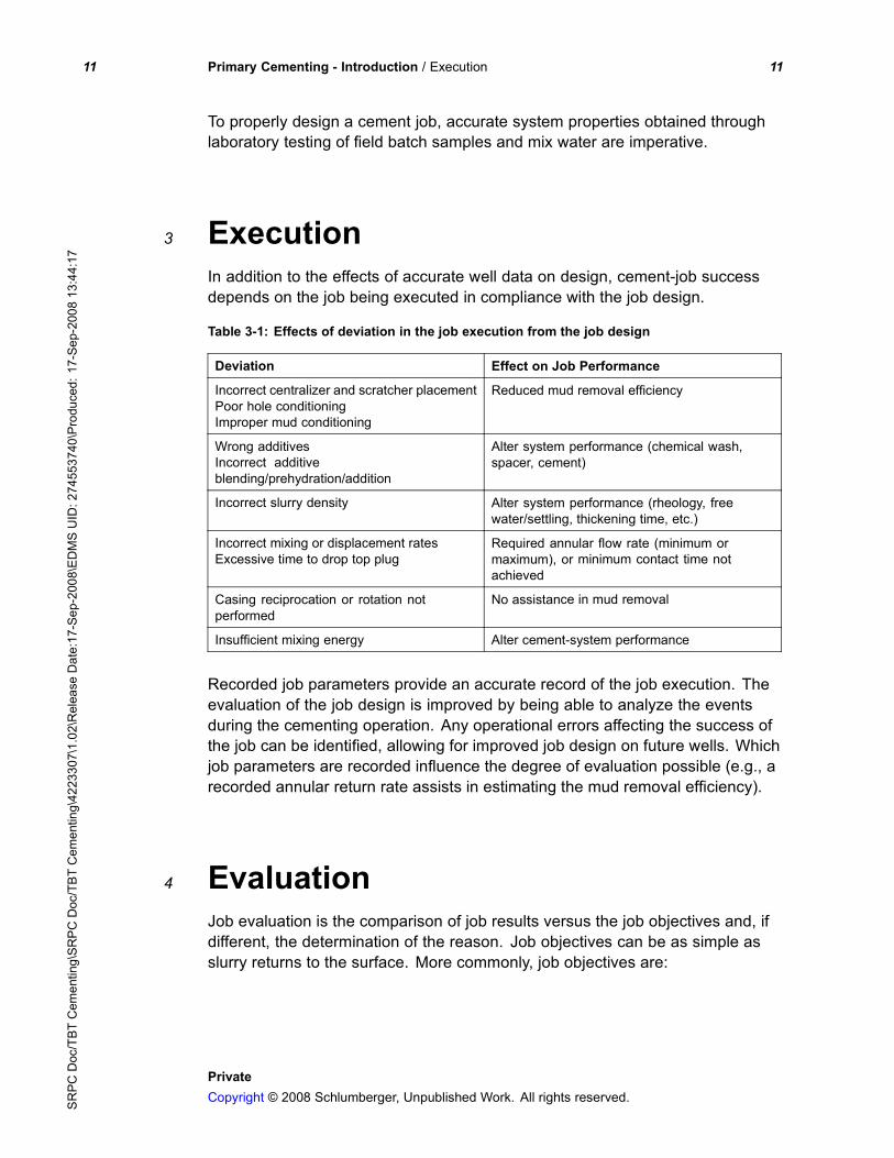
To properly design a cement job, accurate system properties obtained throughlaboratory testing of field batch samples and mix water are imperative.
3 ExecutionIn addition to the effects of accurate well data on design, cement-job successdepends on the job being executed in compliance with the job design.
Table 3-1: Effects of deviation in the job execution from the job design
Deviation Effect on Job Performance
Incorrect centralizer and scratcher placementPoor hole conditioningImproper mud conditioning
Reduced mud removal efficiency
Wrong additivesIncorrect additiveblending/prehydration/addition
Alter system performance (chemical wash,spacer, cement)
Incorrect slurry density Alter system performance (rheology, freewater/settling, thickening time, etc.)
Incorrect mixing or displacement ratesExcessive time to drop top plug
Required annular flow rate (minimum ormaximum), or minimum contact time notachieved
Casing reciprocation or rotation notperformed
No assistance in mud removal
Insufficient mixing energy Alter cement-system performance
Recorded job parameters provide an accurate record of the job execution. Theevaluation of the job design is improved by being able to analyze the eventsduring the cementing operation. Any operational errors affecting the success ofthe job can be identified, allowing for improved job design on future wells. Whichjob parameters are recorded influence the degree of evaluation possible (e.g., arecorded annular return rate assists in estimating the mud removal efficiency).
4 EvaluationJob evaluation is the comparison of job results versus the job objectives and, ifdifferent, the determination of the reason. Job objectives can be as simple asslurry returns to the surface. More commonly, job objectives are:
PrivateCopyright © 2008 Schlumberger, Unpublished Work. All rights reserved.S
RPC
Doc/TBT
Cementing\SRPCDoc/TBTCementing\4223307\1.02\ReleaseDate:17-Sep-2008\EDMSUID:274553740\Produced:17-Sep-200813:44:17

12 Primary Cementing - Introduction / Organization of primary cementing information 12
• achieve the desired cement tops to protect the casing from corrosion, toprovide adequate casing support and to maintain well control during thecement placement and setting,
• provide a seal at the casing shoe (or at the top of a liner) and support for theuncemented casing,
• provide zonal isolation across the zones of interest and the nuisance zones(e.g., unwanted water and gas zones).
When job objectives are achieved, the well can be completed and produced ina safe and efficient manner. When a failure is detected, remedial cementingoperations are required, which result in loss of rig time and increased costs. Forthese reasons, a job evaluation is required as soon as possible after every job.
When job objectives are not met, an effective job evaluation will identify thereasons. The design of future wells can then be improved to achieve the jobobjectives.
5 Organization of primary cementinginformationThe manual sections on primary cementing address the design, execution andevaluation topics common to the ”average” well (i.e., the information requiredon a regular basis). These sections are not intended to cover every specialconsideration or related topic; otherwise, the majority of the manual informationwould fall under the primary cementing topic, which would make it difficult forthe reader to find specific information.
Instead, the DEE process will be logically presented, and where specialconsiderations (e.g., gas migration, foamed cementing, horizontal wellcementing, etc.) or additional information sources (e.g., rheology, mixing energy,cement testing, etc.) are applicable, they will be briefly presented and thenreference made to later sections.
A quick review of the manual’s table of contents illustrates the modularity of themanual organization, and the location of other manual sections, many of whichare relevant to primary cementing.
PrivateCopyright © 2008 Schlumberger, Unpublished Work. All rights reserved.SR
PCDoc/TBT
Cementing\SRPC
Doc/TBT
Cementing\4223307\1.02\ReleaseDate:17-Sep-2008\EDMSUID:274553740\Produced:17-Sep-200813:44:17

13 Primary Cementing - Introduction / List of Acronym 13
List of Acronym
Term Definition
BHCT BottomHole Circulating Temperature
BHST BottomHole Static Temperature
BOP BlowOut Preventer
DEE Design Execute Evaluate
TOC Top Of Cement
WOC Wait On Cement
PrivateCopyright © 2008 Schlumberger, Unpublished Work. All rights reserved.SR
PCDoc/TBT
Cementing\SRPC
Doc/TBT
Cementing\4223307\1.02\ReleaseDate:17-Sep-2008\EDMSUID:274553740\Produced:17-Sep-200813:44:17