celtic ff - plumbasethe celtic ff is a wall mounted, low water content fan- ned balanced flue...
TRANSCRIPT

Celtic FF ROOM SEALED FANNED BALANCED FLUE
COMBINATION BOILER
G.C. No. 47 980 01 FROM SERIAL N” 391061863
This appliance has been tested and certificated by British Gas (For use on natural gas only)
.
I lil Ill
Installation and Servicing Instructions
(leave these instructions with the user)
Looking Good. Heating Better

The CELTIC FF is a wall mounted, low water content fan- ned balanced flue appliance suitable for central heating and hot water via a non storage wapr to water heat exchanger. The maximum out pufis24.0 kW (81,900 Btu/h).
The boiler is designed for sealed systems only and inclu- ded in the appliance is the expansion vessel, circulating pump, temperature and pressure gauges, safety valve and electric connection box. The flue which is 100 mm (4 in) dia pipe, can be directed to the rear or to the left or right and can be extented to a maximum length of 3 m, or 1.6 metres horizontally using the available 90” bend (see sections 1.4.1, 1.4.2 and 1.4.3 figures 2.3.3a. 3b, 3~).
Special features include : -Output to central heating fully range rated between
l/3 and full output.
- High efficiency.
-Special jig plate enabling all pipework to be installed before installing appliance.
- Independent control over central heating flow tempe- rature and hot water.
- Fully adjustable central heating flow temperature.
- regulation between 50” C and 82” C.
- High limit thermostat for both boiler and hot water.
- Integral frost thermostats to protect appliance.
-Water flow switch to protect appliance.
-Suitable for showers with mixer valves which are com- patible with water heaters.
Guarantee
The manufacturer’s guarantee on this appliance is for 12 months from the date of installation. The guarantee is void ; if the appliance is not installed in accordance with the recommendations made herein.
1.1 DIMENSIONS
1 I ’ I
REAR OUTLET
/ T _- F
SIDE OUTLET
- -
A B C D E F c H J K 1 M N P R S T
-
mm in
820.5 32.3 391.0 15.4 365.0 14.4 100.0 4.0 169.5 6.7 654.5 25.7
43.0 1.7 50.0 2.0 75.0 3.0
260.0 10.2 150.0 6.0 972.5 38.3
13.0 0.5 61.0 2.4 30.0 1.2
152.0 6.0 112.0 4.4
2

1.2 Technical Data
Hot water Input ....................... output .....................
Water flow rate raised 45” C (81” F) ................ Water flow rate raised 30” C (54” F) ................ Maximum temperature ....... Maximum pressure .......... Minimum working pressure. ... Gas rate .................... Burner pressure .............
Central heating Maximum input. ............. Maximum output ............ Gas rate (maximum) .......... Burner pressure ............. Minimum input .............. Minimum output ............. Gas rate (minimum) .......... Burner pressure ............. Minimum flow rate ........... Maximum pressure ..........
Manifold injectors 14 off ...... Pilot injector ................ Manifold restrictors 213 valve
l/3 valve.
28.41 kW j6.940 Btulh 24.0 kW II ,900 Btu/h
7.6 L/min 1.7 gal/min
11.4 L/min 2.5 gal/min 60” C 140” F 10 bar 150 psi 1 bar 15 psi
2.7 m3/h 95.35 ft3/h 12.5 mbar 5.0 in wg
28.41 kW ,6.940 Btu/h 24.0 kW II ,900 Btu/h 2.7 m3/h 95.35 ft3/h
12.5 mbar 5.0 in wg 11.6 kW 39580Btulh 8.0 kW 17.300 Btu/h
1 .O m3/h 35.31 ft3/h 1.5Tbar 0.6 in wg 300 L/h 1 .I gal/min 3.0 bar 44 psi
Natural gas 1.28 mm 0.05 in 0.3 mm 0.01 in 4.5 mm 0.18 in 2.3 mm 0.09 in
1.3 Minimum clearances around Boiler Top above air duct 50 mm (2 in) Bottom below case 200 mm (8 in) Sides 100 mm (4 in) Front 600 mm (24 in)
1.4 Wall Thicknesses
Connections
Gas .._.............. 22 mm copper Heating flow 22 mm copper Heating return ..__. _............ 22 mm copper Mains cold water inlet 15 mm copper Hot water outlet 15 mm copper
Electrical supply 240 V - 50 Hz, fused at 3A. Electrical input 195 watts Internally fused, two at F2A (BS 4265) Weight .._. _.......... Watercapacity _......... _.......... I ,“iiZs I 1;::
Ignition - Anstoss continuous spark generator
Electrode - Chaffoteaux Ltd. spark gap 5 mm Boiler thermostat - EGO (82” C)
Boiler limit thermostat - Sopac (85” C)
Hot water limit thermostat - Sopac (57” C + 3” C) Safety overheat thermostat Tokoswitch - (105” C) Frost thermostats Elmwood - (3” C and 11” C)
Gas valve - AEMF
Fan motor - SEL Pressure switch - Dungs
Pump head -Grundfos UP 15/60 Expansion vessel initial charge pressure - 0.65 bar (9.6 PSI)
The standard flue assembly can accomodate the following thicknesses. Rear : from 55 mm to 576 mm Side : from 55 mm to 392 mm (This allows for a minimum clearance of 100 mm between the appliance and the side wall. As this dimension increases, so the maximum side wall thickness available decreases). Extention flue assemblies are available to accomodate wall thicknesses of :
Rear : from 577 mm to 2876 mm Side : from 393 mm to 2692 mm
See figs. 2 and 3 for details of number of extensions required.
IMPORTANT NOTE : The extension ducts supplied, up to a maximum of 3, will in fact permit a greater length than indicated to be covered. The ducts MUST be cut so that the maximum length from the centre line of the flue turret to the outermost point of the air duct DOES NOT EXCEED 3 metres. Greater length must not be used.
3

1.4.1
1.4.2 Side Flue Outlet To cut flue assembly to length - Measure from external wall face to centre line of
external internal
FM
Celtic and subtract 37 mm (this will give required wall face wall face length ‘I”).
IL) L 50 - Cut off surplus from plastic air duct (plain end). mm, N-6. If extension sections are used ensure these are
.-I 1 I *j -_--- )-- “--P, --t-l-f-
firmly pushed together.
1 - Cut same amount off aluminium flue duct (plain L-&L- 7 end).
Flue extension accessory
L Par-t NO. 61061
700 mm max. (standard length) (I metre length)
q 1 1
13mm -I /y/q- 55 mm 1
9 I r--
295 ’ mm min min. min.
Fig. 3 SIDE OUTLET ASSEMBLY cut off from this end ci I- _ - _I
<- 7, \
I I \ a- L : -----c
standard 2 part flue duct Fig. 3a PLASTIC AIR DUCT ALUMINIUM FLUE DUCT Fig. 3b
1.4.3 Other flue arrangements
Rear Flue Outlet To cut flue assembly to length - Measure wall thickness (T). - Add 74 mm, this will give required length CL). - Mark plastic air duct for length (L) and cut off sur-
plus (from plain end). N.B. If extension sections are used ensure these are firmly pushed together, see figs. 3b and 3c. - Cut off same amount from aluminium flue duct
(plain end).
Flue extension accessory Part No. 61061 (I metre length)
Fig. 2 REAR OUTLET ASSEMBLY
1. Distance from internal corner 300 mm without kit, 150 mm with kit no. 76216 (GC No, 264 833).
OE WI L”E
? 5
OE L”E f
1 \ 2
Fig. 3c
2. Distance below balconies or eaves 200 mm without kit, 150 mm with kit no. 76216 (GC No 264 833).
3. Appliance is normally supplied packed with standard 650 mm straight flue section. Addi- tional straight extention lengths of 1 metre. Part No. 62823 (GC No 264 459), can be used up to a total straight length of 3 metres. It is also possible to incorporate one bend in the flue using Part No. 65572 (GC No. 264 835). In this case the length Ll + L2 should not exceed 1,6 metres horizontally.
4

1.5 Description
Fig. 4
The appliance is mounted in a steel case which has a whi- te epoxy resin paivt finish. 1. Chassis : The chassis is a rigid plated mild steel pressing on which all components are mounted.
2. Flue hood : Is an aluminium alloy casting onto which the two speed fan is mounted.
3. Combustion chamber : This is assembled from a number of components moun- ted onto the chassis. The front panel is simply removed for servicing complete with the expansion vessel, hooks are fitted below the appliance to accept and retain the panel during servicing.
4. Expansion vessel : The expansion vessel has a capacity of 5,4 litres (1.19 gal) and is sized for a normal system water content whe- re the-load is equivalent to the maximum output of the boiler. The charge pressure is 0.65 bar.
5. Pilot security is by thermocouple flame failure :
6. Multigas burner cbmprising : stainless steel blades (14) and a manifold with injectors (14).
7. Gas section including thermoelectric valve and two stage valves.
8. Secondary heat exchanger : The secondary heat exchanger is a plate type heat ex- changer. A thermostat is fitted on the pipework limiting the domestic hot water temperature to a maximum of 5733” c.
9. Change over valve : The valve is activated by a demand for domestic hot wa- ter, closes the heating circuits, and directs water to the secondary heat exchanger.
10. Electricial box containing : Mains connection Fuses Printed circuit board Connections for external controls Connections for fan, pressure switch and Flow Switch Connections for pump
11. Solenoid valve : Block on which 3 valves are mounted : l/3 valve - 1st stage valve-heating and hot water (blue) 2/3 valve - full output to hot water (black) 2/3 valve - (variable valve) central heating (orange).
12. Grundfos pump motor
13. Air separator and vent directly connected to the pump inlet (not illustrated).
14. Regulation screw to adjust output to heating (2/3 valve).
15. Heating body comprising : Copper finned tube heat exchanger protected with sili- cone resin paint. Combustion chamber in aluminium coated steel. Combustion chamber lining - ceramic fibre panels.
16. High limit thermostat.
17. Water service tap (not illustrated)
18. Flow isolating valve - heating (not illustrated).
19. Gas service tap (not illustrated).
20. Domestic hot water outlet (not illustrated).
21. Safety valve with drain tap (not illustrated)
22. Heating return isolating valve with filter (not illus- trated).
23. Ignition button.
24. Thermometer indicating boiler flow temperature
25. Temperature selector for domestic hot Water
26. Selector switch - hot water only/OFF/heating and hot water.
27. Thermostat to regulate heating flow temperature.
28. Pressure gauge.
29. Pressure switch.
30. Integral frost thermostats.
31. Water flow switch.

1.6 Description of Operation 1.6.3 Hot Water (see fig. 6) 1.6.1 The Celtic FF is a dual purpose or combination boiler
providing central heating and hot water. Hot water is provided on a demand basis. For the duration of the demand for hot water the central heating is interrup- ted. The appliance operates in two modes. A hot water only setting where it operates only on hot water de- mand and a hot water + central heating setting providing central heating and switching to hot water on demand.
1.6.2 Central Heating (see fig. 5) The pump (21) circulates water which returns to the boiler via the return valve (31) which incorporates a filter (30). Before reaching the pump it passesthrough an air separator and air purger (17). The return water passes through the heat exchanger (2) where it is heated. It then pcsses through the change over valve (19) which in heating mode is in its rest position (fig. 3) and out via the flow valve (27) to the radiator circuits (34). The boiler thermostat (8) controls the temperature of the circulation water between a minimum of 50” C approx and a nominal maximum of 82” C. The boiler thermostat also controls the opening of the l/3 (I I) and variable solenoid valve (IO). The limit thermostat (16) set to 85” C closes both so- lenoids valves in the event of its set temperature being reached as could occur under the low flow conditions. The boiler is protected by a high limit thermostat (4) the operation of which interrupts the thermocouple and extinguishes the pllot. If the high limit thermo- stat operates it is necessary to manually re-establish the oilot
When there is a demand water flows through the water section part (35) of the change over valve (19). The inclusion of a venturi (24) produces high pressure under the diaphragm (231 causing it to rise. This movement IS transmitted to the change over valve closing the heating port and opening the hot water port, as shown (20). The primary water heated by the boiler now passes through the water to water heat exchanger (18) where it flows through alternate pla- tes indirectly heating the DHW.
The rising of the change over valve spindle causes :
1. The opening of a microswitch stopping the pump. This circuit is remade by a second microswitch making when the hot water port is fully open.
2. The by-passing of the boiler thermostat brings the boiler under control of a fixed temperature thei-mo- stat (32) which operates on the 2/3 fixed solenoid (12).
3. The selection-of the ‘l/3 valve and the fixed 213 valve. The water temperature is under control of the user and the opening of the regulator (25) increases the flow of the water and thus reduces the temperature.
When the regulator is closed - hottest setting, lowest flow - a limiting thermostat (32) prevents the secondary hot water temperature exceeding 60” C by cycling the solenoid valve without interrupting the flow of water.
CENTRAL HEATING ‘I-1 1
Fig. 5 Ll
‘I-1 1 HOT WATER
:ig. 6 Id
6

1.6.4 Gas (see figs. 5 and 6)
1.6.5
When the main gas tap (33) is turned to the on posi- tion gas is admitted to the gas section (7). Pressing the ignitor button (9) operates a microswitch causing the commencement of a firing cycle. The fan chan- ges from low to high speed and after a purge period of approx 14 seconds a continuous stream of sparks are delivered lighting the pilot gas (3). Simultaneously, the thermoelectric valve (14) is opened and after a further 5 seconds, sufficient energy is being produ- ced by the thermocouple (5) for the thermoelectric valve to be retained in the open position.
When the ignitor button is slowly released gas is ad- mitted to the underside of the solenoid valves (IO, 11 and 12).
There are 3 solenoid valves (I) the centre (blue) valve (11) fixed at l/3 of max rated output, (2) the right hand hot water (black) valve (12) fixed at 213 of maxi- mum rated output, (3) the left hand central heating (orange) valve (IO) which is variable up top 2/3 maxi- mum rated output.
The gas admitted by the orange valve is varied by ad- juster (6).
FUNCTIONAL FLOW DIAGRAM
1 1 Switch 1 1 S$Toff 1 \siq S!!h 1 Pressure over Switch on Valve
,r 11°C
- Frost Thermostat
Limit
Boiler 82°C Control
Thermostat
113 C Blue Solenoid
Fig. 7
1.6.6 Safety Controls In addition to the normal safety controls the CELTIC FF incorporates the following features. Should the central heating water flow reduce to be- low 300 L/h (1.1 gal/min) the gas supply to the burner is turned off, see figs 3 & 4 (36).
Built in boiler protection is provided by turning the burner and pump on if there is any risk of frost da- mage.
7

I OR. ORANGE GN. GREEN YELLOW B. BLUE I R. RED I IGNITION BUTTON
SELENOID VALVE
BK. BLACK v. VIOLET BR. BROWN W WHITE BOILER TH. HOT
* WATER
8. BK. 213
240V .1-I. 1 III 2
EXTERNAL CONTROL
PRINTED CIRCUIT
= B & R B’
240 V, - SELECTOR SWITCH -.
r-4
I - r u WATER FLOW 1 24V
1 e)L- xwITCH Or E Bk
’ ‘Ll Bk
FAN CAPACITOR/
PRESSURE SWITCH I 3
BOILER THERMOSTAT HEATING
Fig. 9
ILLUSTRATED WIRING DIAGRAM
L
8
2 INSTALLATION REQUIREMENTS 2.1 General
The installation of the boiler must be in accordance with Gas Safety (Installation and Use) Regulations 1984, Building Regulations, current I.E.E. Wiring Regulations and the Byelaws of the Local Water Undertaking. It should be in accordance also with the BS Codes of Practice and the British Gas Specifica- tions for Domestic Wet Central Heating Systems and any relevant requirements of the local Gas Region and Local Authority Building Standards (Scotland) Regulations. Detailed recommendations are stated in the following British Standard Codes of Practice : BS 6891 : 1988, BS 6798 1987, BS 5440 1979, BS 5440 : 1 1990 and 2 : 1989, BS 5449 : 1 1990. Note : Gas Safety Installation and Use Reg 1984. It is thelawthatallgasappliancesareinstalledbyC.0.R.G.I. Registred persons in accordance with the above regulations. Failure to install appliances correctly could lead to prosecution. It is in your own interest and that of safety to ensure compliance with the law.
2.2 Location The boiler is not suitable for external installation. The position chosen for the boiler must permit the provi- sion of a satisfactory flue termination. The location must also permit adequate space for servicing and air circulation around the boiler. The surface on which the boiler is mounted must be of non combustible material. The boiler may be installed in any room or internal space although particular attention is drawn to the requirements of the current I.E.E. Wiring Regulations and, in Scotland, the electrical provisions of the Buil- ding Regulations applicable to Scotland, with respect to the installation of a heater utilising mains electricity in a room or internal space containing a bath or shower. Where the installation of the boiler will be in an unusual location special procedures may be necessary and BS 5546 gives detailed guidance on this aspect. A compartment used to enclose the heater must be designed and constructed specifically for this purpose. An existing cupboard or compartment may be used provided that it is modified for the purpose. Details of essential features of cupboard/compart- ment design are given in BS 6798: 1987.
2.3
2.4
Water Circulation System The Celtic FF is suitable for SEALED SYSTEMS only and should be in accordance with the relevant recommen- dations given in BS 6798: 1987, BS 5449:l (for the smallbore or/and microbore systems) and the British Gas Specifications for Central Heating Systems.
Siting the Flue Terminal Refer to section 1.4 for details of wall thicknesses which can be covered.
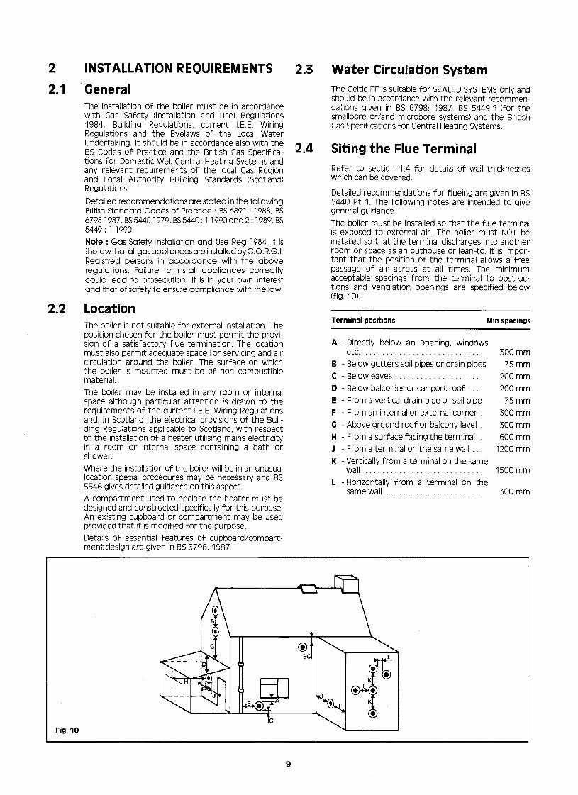
Detailed recommendations for flueing are given in BS 5440 Pt 1. The following notes are intended to give general guidance. The boiler must be installed so that the flue terminal is exposed to external air. The boil& must NOT be installed so that the terminal discharges into another room or space as an outhouse or lean-to. It is impor- tant that the position of the terminal allows a free passage of air across at all times. The minimum acceptable spacings from the terminal to obstruc- tions and ventilation openings are specified below (fig. IO).
Terminal positions Min spacings
A - Directly below an opening, windows etc. .._ .__..., ,....,
B - Below gutters soil pipes or drain pipes C - Below eaves D - Below balconies or car port roof E - From a vertical drain pipe or soil pipe F - From an internal or external corner G - Above ground roof or balcony level H - From a surface facing the terminal J - From a terminal on the same wall K - Vertically from a terminal on the same
wall .._ ..__.., L - Horizontally from a terminal on the
same wall
300 mm 75 mm
200 mm 200 mm 75 mm
300 mm 300 mm 600 mm
1200 mm
1500 mm
300 mm
Fig. 10

Note : The flue can be extended to clear a projection. BUILDING REGULATIONS 1985 excerpt. Approved document J Part B 1.4 (C) (D).
C) Protect with a terminal guard if it could come in contact with people near the building or be subjected to damage.
D) Designed so as to prevent the entry of any matter which might restrict the flue. (A terminal guard G.C. No 381 782 is available from).
Quinnel Barret & Quinnel Wireworks Old Kent Road London SE15 1NL Tel. 08 1-639-l 357
The air inlet/outlet duct and the terminal of the appliance must not be closer than 25 mm (1 in) to any combustible material Detailed recommendations on the protection of combustiable material are given in BS 5440 Pt 1 : 1990. IMPORTANT NOTICE : TIMBER FRAMED HOUSES IF THE APPLIANCE IS TO BE FITTED IN A TIMBER FRA- MED BUILDING, IT SHOULD BE FITTED IN ACCORDANCE WITH THE BRITISH GAS PUBLICATION - “GUIDE FOR GAS INSTALLATIONS IN TIMBER FRAMED HOUSING” reference DM2. IF IN DOUBT, ADVICE MUST BE SOUGHT FROM THE LOCAL REGION OF BRITISH GAS.
2.5 Air Supply The room in which the boiler is installed does not re- quire a purpose provided air vent. If the boiler is installed in a cupboard or compartment permanent air vents are required in the cupboard or compartment, one at high level and one at low level either direct to the outside air or to a room. Both high and low level air vents must communicate with the same space.
2.6
Position of vents Air from room Air direct from outside
High level 264 cm2 (40 in2) 132 cm2 (20 in2)
Low level 264 cm2 (40 in2) 132 cm2 (20 in2)
Electrical Supply - This appliance must be earthed. - All wiring external to the appliance must conform to the current I.E.E. Regulations. - The Celtic FF requires a 240 V + 50 Hz supply. - Connection of the appliance and any system controls to the mains supply must be through a common isolator and must be fused at 3A maximum. This should preferably be an unswitched shuttered socket outlet and 3 pin plug to BS 1363. Alternatively, a double pole isolating switch may be used, provided it has a minimum contact separation of 3 mm in both poles. The isolator should be clearly marked showing its purpose, preferably positioned close to the appliance. - Fuse the supply at 3A. - The supply cord must be 0.75 mm* (24 x 0.2 mm) three core to BS 6500 Table 16.
2.7
3.
3.1
Gas Supply The Celtic FF requires : 2.7 m3/h (95.35 ft3/h) gas flow. The meter and supply pipes should be capable of deli- vering this quantity of gas in addition to the demand from any other appliances in the house. The complete installation must be tested for soundness as described in BS 6891 : 1988
SYSTEM GUIDANCE
General The low water content CELTIC FF dual purpose boiler includes the expansion vessel, safety overheat ther- mostat, temperature and pressure gauges, and safe- ty valve. The thermostat is adjustable and on its maximum setting gives a nominal 82” C (180” F) flow tempera- ture. Detailed recommendations for water circulation are given in BS 5546 : 1990. Whilst the boiler provides hot water, there may be occasions when a cylinder will be used, for instance, if the property has two bathrooms. Detailed recommendations of this appli- cation are given in sections 3.13 to 3.16 Thermostatic control should be used in the heating circuits and the cylinder if one is fitted. It must be remembered that a combination appliance has a limited volume of hot water that can be sup- plied at any one time for a given temperature. Indeed in most respects it is equivalent to a multipoint water heater and many of the contraints associated with multipoints apply equally to combination boilers. The appliance has two separate functions, to provide heating and hot water on demand. It can have a third which is to supply hot water high demand through the use of an indirect cylinder. Such a course could recommend itself if, for instance, there is more than one bathroom or if the standard and appointments of the property, such as basins in all bedrooms and a large kitchen indicate a high usage of hot water. Hot water produced indirectly through a cylinder can be used to satisfy high simultaneous demand outlets - bathrooms etc. whilst the benefits of high efficien- cy in generally small quantities of hot water, can be fully utilised in kitchens, cloakrooms and so on. Figs. 14, 15, 16 and 17 indicate various layouts for the production of hot water. It is recommended that only a high recovery cylinder is used and circumstanceS may from time to time dictate that a special saturated heat exchanger in an indirect cylinder may be desira- ble. Separate time and temperature control over hot water generated in this way can be achieved by the use either of two port valves or three port valves of a flow share or priority pattern (see notes on drawing). It is also possible, where the occupation of the house is variable, to provide either for a small or large load. This is best achieved with a tall, small diameter cylinder. See section 5 for possible wiring arrangements. When using the hot water side of the appliance the use of non-return valves and/or loose jumpered stop cocks is just as critical as with the conventional multi- point and should be avoided. If a non-return valve is fitted in the incoming water supply then an expan- sion vessel MUST be fitted in the domestic hot water circuit with a capacity of at least 0.16 litres.
10

3.2
3.3
3.4
If the mains cold water supply is in excess of 10 bar (150 psi) a pressure limiter must be fitted to avoid excessive pressure being applied to the boiler. When replacing an existing cylinder storage system with CELTIC FF it is essential that all redundant pipe- work is removed and dead legs eliminated. In properties where there are multiple draw-off points on different levels consideration should be given to the use of non-return valves in the secondary hot water system to avoid “active dead legs”. No-non re- turn valve should be less than 3 ft (I m) above the top of the appliance and ideally should be as close as possible to the terminal fitting.
System controls The boiler is electrically controlled and is suitable for most control schemes currently available including thermostatic radiator valve and motorised valves. When using motorised valves the controls should be arranged to switch off the boiler when circuits Bre satisfield. The boiler requires a minimum flow rate of 300 L/h (1.1 gal/min) and consequently, if thermostatic radiator valves are fitted to all radiators, a by pass will be necessary. This will ensure that the boiler will operate correctly when all TRVs are closed.
Pump The boiler is fitted with a Grundfos UP. 15/60 pump head. The graph (fig. 11) indicatesthe residual head available for the system.
flow rate in g.p.m. 1 2 3 4 5
Fig. 11
Expansion vessel The expansion vessel which is fitted on-the front of the combustion chamber maintains pressure and accomodates system water expansion. The vessel has a capacity of 5.4 litres (1.19 gals) and is charged to a pressure of 0.65 bar.
The connection in the centre of the expansion vessel is not a vent point.
At the design flow temperature and the initial system pressures quoted the maximum allowable system volume is 75 litres.
3.5
3.6
3.7
3.8
If the water volume is not known and cannot be accurately assessed from manufacturers data the following volumes may be used to give a conservative estimate of the system volume.
Boiler .4 litres (0,8 gals) Small bore pipework .0.3 litres (0.07 gals)
per 0.292 kW Microbore pipework .7 litres (1.5 gals) Steel panel radiators .2.3 litres (0.5 gals)
per 0.292 kW (1000 Btu/h) of system output Hot water cylinder .(0.44 gals)
If the volume exceeds 75 litres an additional vessel will be required fitted in the flow from the appliances. Refer to BS 7074 Pt. 1 or BS 5449 for details of sizing. Mains Water Connection There shall be no permanent connection to the Heating System Pipework for filling or replenishing without the approval of the Local Water Authority.
Filling point (see BS 6798: 1987 Appendix A)
Filling and recharging can be done : I) Through a temporary hose connection from a draw off tap supplied from a service pipe under mains pressure provided that this is acceptable to the Local Water Authority, see fig. 12). 2) Through a self contained unit comprising a cistern, pressure pump if required and if necessary a pressure reducing valve or flow restrictor, fig. 13. 3) Through a cistern, used for no other purpos-, per- manently connected to a service pipe. The static head available must be sufficient to provide the designed initial system pressure.
Make up system Provision must be made for replacing water lost from the system indicated by a reduction in pressure shown on the pressure gauge. Recharge through the filling point (see section 3.6).
Pipework should be of copper, small bore or microbo- re with capillary or compression jointing to a high standard, leak sealant must not be used in the system.
11

heating system
f\ anti-vacuum valve
this method may only be used if acceptable to the Local Water
complies with BS 6798
appendix A, method A. 1. stop non-return valve
valve
test co&k
Fig. 12
heating system overflow
L
cistern Note : Cistern to be supplied
-1 1-1
through a temporary complies with
BS 6798 \ -7-w . connection from the ----,A/ service pipe or cold
appendix A stop valve I reducing valve pressure pump water distributing pipe.
method A2 (if required)
Fig. 13
3.9.1 Boiler replacement (retrofit) 3.11 Inhibitors In an old system where the boiler is being replaced, we recommend the use of a strainer, fitted with a drain tap on the heating return, designed to retain scale particles and other solid debris. It is godd practice to use a chemical cleaner with a floctuating agent, used as recommended by the cleanser manufacturer, to clean the system before the old boiler is removed.
Chaffoteaux Ltd do not generally recommend the use of inhibitors in systems using the Celtic FF boiler. It is however, appreciated that the use of a corrosion and limescale inhibitor may be desirable or specified. The following are the appliance manufacturer’s recommendations :
1) Use only a British Gas or similar approved inhibitor from the Fernox Manufacturing Company Limited
3.9.2 Existing systems Valves and joints should be carefully checked for leaks and the appropriate action should be taken either as a repair or replacement. The old open system has probably only been subjected to a pressure of 0.4 bar or less. When you change to a sealed system where the charge pressure will be 1.0 bar and the running pressure exceeding 1.5 bar, consideration should be given to the replacement of radiator valves with a pattern capable of sealing at the higher pressures.
3.10 Cylinder Where a domestic hot water cylinder is used with the Celtic FF it MUST be of the Indirect and high recovery type to BS 1566:Pt I. Single feed cylinders are not suitable for use with this appliance. Flow and return pipework to the cylinder should be in 22 mm copper pipe.
Britannica Works, Clavering,-Essex CBl 1 4QZ - Tel : 0799 085811 ; Grace Service Cheminal, Grace Dearbon Ltd - Widness - Cheshire WA8 8 UD Tel : 051 424 5351 - Telex : 627 341 - Fax : 051 423 2722 2) Use only the quantities specified by the inhibitor manufacturer. 3) Cleanse the system as required by the inhibitor manufacturer.
4) Add inhibitor only after flushing when finally re-filling the system.
3.12 Add-on devices It is important that no external control devices eg. economisers be directly fitted to this appliance unless covered by these installation instructions or agreed with the manufacturer in writing. Any direct connection of a control device not approved by the manufacturer could make the guarantee vaid and also infringe the Gas Safety (Installation & Use) Regulations 1984.
12

Heating & stored hot water - spring return
1 1 valves only
Heating & stored hot water using flow share
relay required
Fig. 15
1 Remote by-pass
Celtic
remote by pass with L/S valve
hot water
3.13 Heating and hot water systems It must be remembered that a combination appliance has a limited volume of hot water that can be sup- plied at any one time for a given temperature. Indeed in most respects it is equivalent to a multipoint water heater and many of constraints associated with mul- tipoints apply equally to the combination boilers. The appliance has two separate functions, to provide heating and hot water on demand. It can have a third, which is to supply hot water high demand through the use of an indirect cylinder. Such a course would recommend itself if for instance there is more than one bathroom. If the standard and appointments of the property such as basins in all bedrooms and a large kitchen indicate a high usage of hot water.
3.14
3.15
Hot water produced indirectly through a cylinder can be used to satisfy high simultaneous demand outlets - bathrooms etc. Whilst the benefits of the high effi- ciency in generally small quantities of hot water, can be fully utilised in kitchens, cloakrooms and so on. Figs. 14, 15, 16 and 17 indicate various layouts for the production of hot water. It is recommended that only a high recovery cylinder is used and circumstances may from time to time dictate that a special saturated heat exchanger in an indirect cylinder may be desirable. Separate time and temperature control over hot water generated in this way can be achieved by the use either of two port valves or three port valves of a flow share or priority pattern (see notes on drawing). It is also possible, where the occupation of the house is variable, to provide either for a small or large load. This is best achieved with a tall, small diameter cylinder (fig. 16, see sections 5 for possible wiring arrangements).
When using the instantaneous side of the appliance the use of non-return valves and/or loose jumpered stop cocks is just as critical as with the conventional multipoint and should be avoided. If a non-return valve is fitted in the incoming water supply then an expansion vessel MUST be fitted in the domestic hot water circuit with a capacity of at least 0.16 litres When replacing an exisiting cylinder storage system with an instantaneous type system it is essential that all redundant pipework is removed and dead legs eliminated. In properties where there are multiple draw off points on different level consideration should be given to the use of non-return valves in the secondary hot water system to avoid “active dead legs”. No non- return valve should be less than 3 ft (I m) above the top of the appliance and ideally should be as close as possible to the terminal fitting
3.16 The consideration of heating systems using thermo- static valves should ensure that the minimum flow rate through the appliance is maintained and in this connection the remote by-pass is preferred (see fig. 17).
13

4. INSTALLING THE BOILER A vertical flat area is required for the boiler : 1122 mm high x 591 mm wide (44 in x 23.25 in). The surface on which the boiler is mounted must be of a non reverberating and of a non combustible material. The appliance is supplied in a single carton which contains : I) The chassis with all functional parts attached. 2) Casing comprising : 2 side panels
1 front panel 1 controls fascia cover 1 glass door complete with hinges
3) Mounting bracket comprising : flue guide top support plate spacing strip bottom support plate plastic jig plate connection
4) Plastic bag containing : gas filter/washer 5) Box containing : gas and water connections inc.4 above. 6) Box containing : controi knobs
safety valve wall plugs screws and fixings.
7) Flue assembly : flue turret with pressure differential switch and 1st flue duct section plastic wall liner with terminal flue duct plastic turret cover 2nd flue section
8) Plastic bag containing : flue locking ring ‘0’ ring 2 gaskets - one cork and one rubber 4 mounting screws with washers for flue turret
N.B. (i) Extension flue assemblies are not supplied as standard, and must be ordered to suit (see section 1.4)
4.1
4.2
Fig. 18
Positioning the boiler a) Select the location for the boiler referring to the
dimensions shown in 1.1 and 1.3 terminal location positions (2.4 - fig. IO).
b) Check flue length (see 1.4 - figs. 2 and 3). c) Check clearance on external wall for flue terminal
position (see table 2.4 - fig. IO) d) Assemble the mounting bracket made up from 4
pieces (fig. 18) using 4 thread forming screws. e) If for rear flue installation, remember to include
the flue guide plate E, using 2 thread forming screws.
Rear outlet flue a) Mark vertical centre line for boiler on wall. b) Mark horizontal centre line for 107 mm (4.2 in) dia
wall opening and one for upper bracket fixing screws (A).
c) Using bracket as template mark 4 fixing points (A) and (BL
d) Mark wall for flue opening using flue guide plate. e) Drill the wall for the flue opening using a 107 mm
(4.2 in) core drill. f) Drill 4 fixing holes (A) and (B) 7.9 mm (5116 in) and
plug. g) Fix bracket to wall using 6 mm x 50 mm wood
screws provided.
Fig. 19 N.B. Ensure bracket is square and plumb to vertical centre line before tightening.

4.3 295 mm minimum 4
Side outlet flue a) Mark vertical centre line for boiler on wall (see fig.
20).
IF
! b) Using bracket as template mark 4 fixing slots (A) and (B).
169.5 1 - - ------- *
r
c) Mark horizontal line through the fixing slots (A) and project to side wall.
Fig. 20
4.4
Fig. 21
4.5
Fig. 22
4.6 Water connections a) Make connections to copper tails using either solder capillary fittings or compression type.
4.7 Gas connection
d) Mark vertical axis of flue opening 112 mm (4.4 in) from corner of wall.
el Mark wall for centre of flue opening 169.5 mm above the horizontal on side wall.
f) Drill the wall for the flue opening using a 107 mm (4.2 in) core drill.
g) Drill 4 fixing holes (for (A) top of slot) and (for (B) center of slotl.
h) Fix bracket to wall using 6 mm x 50 mm wood screws provided.
N.B. Ensure bracket is square and plumb to vertical centre line before tightening.
Jig plate N.B. By using the plastic jig plate the piping system can be completed before the boiler is mounted. a) Attach plastic jig plate to bottom bracket using 4.6
mm x 10 hexagonal screws provided (fig. 21). b) Fit copper tails and washers to jig plate, the mains
water inlet tail (M) is the shorter of the two 15 mm tails (fig. 22).
c) The water can either come from above or below using the standard tails provided. The gas must en- ter from below.
Gas and water Tube Thread connections diameter size
Jl Heating return 22 mm 3/4 in K) Hot water outlet domestic 15mm l/2 in 1) Gas inlet 22 mm 3/4 in Ml Mains water inlet domestic 15 mm l/2 in N) Heating flow 22 mm 3/4 in
Pipework a) Fit or cut pipework to connect with copper tails
on jig plate.
a) The gas connection is 22 mm diameter. b) Make the gas connection. N.B. The gas supply pipe must not be less than 22 mm diameter.
IMPORTANT NOTE : At this stage the pipework can be completed and tested before the boiler is positioned. Having completed a Satis- factory test on the pipework the boiler can now be fitted or retained for fitting at a later date.
15

4.8 Fitting the boiler al Before hanging the boiler, uncoil wiring harness
(connections to pressure switch) stored by changeover valve, route through lower part of chassis and up back of boiler, place into clips.
b) Remove plastic jig plate from bracket and retain screws.
c) Hang boiler on mounting bracket, ensure that it is properly located.
N.B. Insert washer into union nut and offer assembly to boiler. Use the plain black 3/4 and l/2 diameter graphited fibre washers for water unions, and the white 3/4 filter/washer for the gas union. d) Connect water union using plain washers, working
from left to right. el Connect the gas union using the filter/washer
packed separately either way round.
Fig. 23
N.B. As an alternative to using the plastic jig plate the tails can be fitted to the boiler before mounting, then connected to the services.
4.9 c) Fit 14 mm tail drain bend using washer provided. d) Fit plastic tube from air separator to nipple on
14 mm tail. N.B. The drain must be 22 mm and the 14 mm drain bend from the safety valve must be installed so that discharge of water is readily visible. A tundish arrangement is acceptable. The connection must NOT be made by a capilary or compression fitting directly betweenthe mmdrain bendandthe22 mmdischarge pipe without an air gap. see fig. 24.
Fig. 24
Fit safety valve , The 22 mm discharge pipe must discharge to the
The safety valve is mounted below the outside of the building where possible over a drain. The
heating return (J) (fig. 22) isolating valve. discharge must be such that it will not be hazardous to
a) Ensure ‘0’ ring is in position within the occupants or cause damage to external electrical
socket from heating return isolating components or wiring. The pipe should be directed downwards. It must not discharge above an entrance or
b) Fit safety valve and secure with grub window or any type of public access as the temperature
screw provides. of the water being discharged may reach 100” C.
c) Remove plastic turret cover (D) from flue turret (B) held by two screws.
d) Peel off protective paper from adhesive side of cork gasket (A) place on mating side of flue turret (B) li- ning up with four clearance holes, press together.
e) Assemble second part of flue duct CH), push fit. f) Slide locking ring (C) and ‘0’ ring over plastic air duct. g) Slide air duct over flue duct, engage end of flue duct
into terminal and locate air duct into turret (B). h) Slide ‘0’ ring along air duct 0, to contact with the
face of the turret (B). Locate lugs on locking ring CC) between lugs on flue turret (B). Push together and turn to lock.
jl Position square channelled rubber gasket (E) on the flue hood outlet of the boiler, channel facing downwards.
k) Pass the flue assembly through the wall and seat turret (B), onto the flue outlet, secure with 4 screws provided.
Fitting the flue up to 700 mm long a) Cut plastic duct (G) to length required, see fig. 2 or
3 dimension CL). b) Cut same amount from aluminium flue duct CH). N.B. In very cold weather the plastic air duct becomes brittle, warm before cutting.
N.B. The terminal must extend 13 mm (0.5 in) past the surface of the external wall. I) Fit wall plate (F) provided With mastic sealing ring
over air duct to structure. m) Make good internal wall face where the air/flue
duct assemblies exit the room. n) Do not fit plastic turret cover ‘D’ until electrical
connections have been made.
16

4.11
4.12
4.13
Fitting the flue over 700 mm long
al Assembly is precisely as detailed in section 4.10 using the requisite number of extension flue and air ducts. In particular note the following.
b) The standard flue duct is always used (both sec- tions) at the appliance end (uncut).
c) The standard air duct is always used at the terminal end (uncut).
d) When cutting, always cut one extension flue duct and the same amount from one extension air duct. Always cut the plain end NOT the socket end.
e) Full details of dimensions and assembly are given in figs. 2 or 3 as applicable.
f) If internal fixtures prevent the assembled ducts being passed through the wall from the inside, the ducts may be pushed through from outside (remo- ve the locking ring VJ and 0 ring first).
Connection to the pressure switch a) The two wires on the harness must be connected. b) Push spade terminals onto tags COM (P) and No (2)
-the common and normally open contacts - polari- ty immaterial.
c) Fitturretcove?(D) (fig.25)ensuringthatboththeair tube and cables are not trapped, with the cable retaining clip positioned as shown, see fig. 26, within the cover. N.B. NC (1) Terminal is not used.
zig. 26
Making the electrical connection N.B. See Section 2.6 for electrical supply requirements THIS APPLIANCE MUST BE EARTHED. a) Pull out fuses (A). b) Remove two screws (B). c) Open door to left hand side of electrical box. d) Cut the cable entries to the size of the cable being
used which should not be less than 0.75 mm2. e) Remove cable clamp. f) Connect permanent live to (L) (Ph) and neutral to N. g) Connect earth to earth pillar ( & ). h) Connect external controls - time clock room ther-
mostat etc. across terminal 4 and 5, (sections 5.1-5.5).
i> Secure cables with cable clamp and locate flex into clip on boiler chassis.
k) Close door and secure with two screws. I) Replace fuses. N-B. The length of the earth wire between the cable clamp and the terminal must be such that the live and
Fig. 27 neutral wires become taut before the earth wire if the supply cord is pulled.
In the event of an electrical fault after installation preliminary electrical system checks must be carried out. Checks to ensure electrical safety should be carried out by a competent person i.e earth continuity, polarity and resistance to earth. Use only voltage free external control switching. No supply voltage should be connected to terminals 3,4 or 5.
17

5.
5.1
5.2
N.B. For additional information contact Time Control Manufacturers
Terminal 3 is a neutral for acceleration if required.
Supply through : 1. Double pole fused
switch spur
2. 13 amp unswitched plug and socket
; boiler terminal block
’ (terminals are not shown in ----------- same order as on boiler -
follow notation).
remove link between terminals 4 and 5.
Fig. 28
Time clock - Time clock and room stat
- The time clock contacts must be voltage free (remove external links). -. The room stat accelerator should be connected if fitted. - Supplv fuse valve 3 amp.
NB. I) X in table indicates no earth connection in time clock. 2) * In table indicates that external links on time clock must be removed. 3) + in table indicates no ‘spare’ connection in time clock so a connector will be required.
room thermostat cylinder thermostat Honeywell T60 60B Honeywell L6 41 A
240 V 50 Hz fused 3 amp.
boiler terminals (remove link4-5)
Fig. 29
18

5.3
5.4
Programmer and zone valves
spring return motorised valves w.ith end switch.
I- --- 1
Fig. 30
room thermostat
boiler terminal block
Honeywell Y plan, Satchwell flow share or Satchwell mini valves to control zones.
Refer to controls manufacturers literature. Live to re- lay coil is the wire in their literature which carries the si- gnal to the boiler.
relay l-
---- 1
,&Jr boiler terminal block
Fig. 31
5.5 Frost thermostat.
The appliance is protected by integral frost thermostats. It is advisable to protect the system from frost damage by fitting an additional remote frost ther- mostat which will over ride the controls whilst the selector switch is set to hot water + central hea- trng (II).
frost thermostat r ---- 1
Fig. 32
19

6. COMMISSIONING
6.1
6.2
6.3
Hot water circuits - filling
I) Check that stop cocks up stream of appliance are of a fixed jumper type.
2) Open mains cold water inlet valve (fig. 33) (A) 3) Vent installation by opening taps and closing. 4) Check that “dead legs” have been eliminated 5) Check for water soundness and rectify if necessary,
Fig. 33
5) Set system charge pressure to design cold pressure. For a new installation we suggest 1.0 bar. For an old system see section (3, 9, 2) set to system static head or 0.8 bar which ever is the greater.
6) Check for water soundness and rectify any leaks. 71 Switch on electrical supply. 8) Manually check bump is free to rotate. Remove
cap (fig. 35 D). Insert small electrical screwdriver (3 mm blade), locate in slot in pump shaft, rotate clockwise to ensure that pump is free replace cap CD).
Fig. 34 9) Switch to HOT WATER + CENTRAL HEATING on Central heating circuits - filling selector switch (A) (fig. 35) switch position (II).
1) Ensure that the isolating valves are open (fig. 34 B 101 Allow pump to run for further IO-15 minutes. and C). N.B. Valve (C) must be turned anti-clockwise Switch OFF. by the knurled nut until it dislocates from the 11) Isolate water supply and drain boiler by disconnecting thread and then pulled out horizontally to its fill system and opening the drain valve (F). This is extremity (approximately 30 mm (1 114 ins)). incorporated in the safety valve and is achieved
2) Fill system to charge condition, see section 3. by screwing down the head until the valve lifts. 3) Vent radiators and any high points. Open all low level drain cocks. 4) Vent automatic air separator/air purger by loosening 12) Remove filter in the return isolating valve (C) and
screw (fig. 35) (E) two complete turns from inspect for any installation debris, see section
closed position. (7.6) to clean and replace.
N.B. Leave screw (E) in open position. 13) Refill system as above.
lighting the boiler I) Purge gas supply. Switch on electrical supply. 2) Turn the lever on the gas service tap (fig. 34) 0 to the
left. In the open position the flame sign is to the front. 3) Temporarily locate the three blue control ‘knobs’ -
one thermostat knob, one ignition button extension and one temperature control knob.
4) Switch to HOT WATER + CENTRAL HEATING (II) on the selector switch (A). The fan will run at low speed.
5) Press the ignition button (R) and hold in. a) The fan will change to high speed to purge the
combustion chamber. Gas is admitted to the pilot.
Fig. 35 b) After approx 14 seconds the spark generator pas-
ses a continuous stream of sparks to light the pilot. ATTENTION :COMMlSSlONlNGINCOLDWEATHER cl When the pilot is alight - viewed through the
This holler is protected by two m-built frost thermostats. During cold weather the boiler sight glass, wait for a further 5 seconds before
may operate under the control of these thermostats. slowly releasing the button. Thus can happen under two conditions : 6) When the button is released, while the boiler is set 1. If the boiler temperature is less than 3’ C (e.g. the boiler has been stored under to heating and any ancillary controls are in demand
very cold conditions) the fan will not run, the pump will operate continuously, It will position, the boiler will fire. still be possible to light the pilot but not the main burner. 7) Check for gas soundness using leak detection fluid. Wait for a few mmutes to allow the heat of the pilot to reset the safety controls permitting the main burner to fire.
8) Check and adjust gas pressure/gas rate, see Section 6.4
2. If the boiler temperature is between 3’ C and 11’ C the frost thermostat will overri- de the external controls. This will cause the marn burner to fire for a few minutes N.B. The thermocouple outp,ut should be checked at and then turn off. Thus applies if the switch is rn posrtion I or II and is quite normal. this stage, should be greater than 12 mv.
20

6.4 Gas rate adjustment
N.B. Before adjustment check gas pressure on the in- let to the appliance, with the appliance working - this should be 20 m bar (8 in wg) for natural gas. The maximum gas rate on hot water is fixed and is a function of the restrictor size. The central heating variable adjuster is factory set at 100 % i.e for an out- put of approx 24.0 kW (81.900 Btu/h). I) Switch boiler to the off (0) central position, see
section 6.3 (fig. 35).
Fig.36
2) Remove the pressure test point screw - (B) and connect a suitable pressure gauge.
3) Remove the hexagonal cap from gas rate adjuster exposing the adjusting screw (CL
4) Switch the boiler to hot water and central heating (II) and check that any fitted external controls are calling for heat.
5) Adjust. Setting pressures are given in graph figs. 37 and 38. The pressure will be reduced by clockwise movement of screw, increased by anticlockwise movement. Now select hot water only, adjust temperature knob, see fig. 4 (25), to minimum and open the largest volume draw-off tap. The gas pressure should now be the maximum as indicated in Technical Data. Now reduce the water flow to minimum and check that the burner reduces its output, this will take a short period of time.
6) Switch boiler off (0). Remove pressure gauge and replace test point screw and gas rate adjuster hexagon cap. Check for gas soundness around screw.
7) Mark the data badge, located on the front of the combustion chamber below the sight glass to indicate output to heating system.
Output/ Burner pressure lnput/Burnerpressure OutputkW lnputft'/h
6
OutputBtdhx103
Fig. 37
k F
2 .G
E 2
2 3 E B
h h
k b f f
2 Ii UIO 125 1.50 1.75 2.00 2.25 2.50 2.75
Input m 3/h
Fig.38
21

6.5
6.6
Remote by pass Adjusting the heating system by-pass Where a by-pass is fitted, see section 3.2, it is necessary to adjust to obtain the boiler minimum flow requirement of 300 I/h (I .I gal/min).
remote by pass with L/S valve
I) Set boiler thermostat to maximum, switch boiler to HOT WATER + CENTRAL HEATING (11).
2) Open all radiators and close the by-pass. Check the temperature rise accross the boiler which should not be greater than 20” C (36” F).
3) Adjust system to minimum load. This is normally done by closing valves on all but two radiators.
4) Open by-pass gradually until the boiler operates quietly and the temperature rise is maintained.
N.B. The by-pass valve should be of the lock shield pattern. The flow switch operates at approx 300 I/h (1 .I gal/min).
Fitting the casing I) Take from the carton the controls cover CH), the
glass door (J1 the top front panel (K) and the side panels (A).
2) Remove control knobs used during testing and commissioning.
3) Fit side panels (A) and secure with screws at bottom rear(B).
4) Put the control cover (H) in posrtion and secure with five screws.
5) Fit the front top panel over the pins at the top of the boiler (0 and secure with two screws at the bottom (D)
6) Fit the various control knobs, gas push button, and domestic hot water temperature selector.
7) To fit the glass door proceed as follows : N.B. THE TIE ROD (G) MUST BE USED
a) Remove the nuts from the machine screws securing the tie rod to the hinges.
b) Offer the door up vertically. Engage part (E) in the profile of the right hand side panel. Fix assembly with screw from beneath (0.
c) Pivot the left hand hinge and engage into profile of the left hand side panel. Fix assembly with screw from beneath.
6.7 HAND OVER THE USERS INSTRUCTIONSAND EXPLAIN THE BASIC FUNCTIONS OF OPERATING THE APPLIANCE. LEAVE THE INSTALLATION AND SERVICING INSTRUCTIONS ADJACENT TO THE GAS SERVICE METER. IF THE ELECTRICITY SUPPLY IS INTERRUPTED THE PILOT MAY HAVE EXTINGUISHED. WHEN THE SUPPLY IS RESTORED RELIGHT THE PILOT SEE SECTION 6.3
22

7.
7.1
7.2
ROUTINE SERVICING
To ensure continued efficient and safe operation of the appliance it is recommended that it is checked and serviced annually. It is the law that any service work must be carried out by a C.O.R.G.I. Registred person. This routine service will normally be confined to :
1) Cleaning the burner.
2) Cleaning the heat exchanger.
3) Checking the gas controls.
4) Cleaning water filters and hoses.
The following schedules are recommended :
a) Check the function of appliance, burner pressure and gas flow rate.
b) Observe flame picture.
c) Check, clean or replace components as necessary.
N.B. Before commencing any work turn off gas at the gas inlet tap (fig. 34) item (G) and ensure that the electricity supply is disconnected. Isolate water supply and drain Appliance if required.
Remove front casing a) Remove two screws (A) bottom rear of boiler. b) Remove screw (B) centre of lower front panel. c) Remove control knobs. d) Remove case by easing forward at bottom and lif-
ting off lugs at top. If necessary, remove the lower control cover (4 screws) and lift off the upper front panel before removing case.
?g. 41
To remove combustion chamber front panel and heating body panels to expose heat exchanger (pri- mary) a) Remove four screws (A) securing the combustion
chamber front panel. b) Lift off front panel complete with expansion vessel
and hang on hooks provided below boiler through matching holes on top folded edge.
N.B. Alternatively support on worktop or floor to avoid damage to flexible tube.
c) Remove eight screws (C) and lift off heating body front panel with access panel (B).
d) Cleantheheatexchangerafterremovingthe burner and pilot, see section 7.7.
Fig. 42
23

7.3
7.4
7.5
7.6
Remove burner assembly
a) Remove two screws (Fl) and remove closure plate by withdrawing forward.
b) Remove four screws (F2) and remove burner by withdrawing forwards, taking care not to trap ignition electrode lead.
c) Remove gasket and retain in safe place,or if adhered to onesutiace, leave alone as removal may damage the gasket.
d) To clean burner see action 7.7.
Fig. 43
To remove pilot a) Remove two screws (A) securing deflector plate
and pilot head. Lift off deflector plate (D) taking care not to damage the electrode tip.
b) Remove pilot air filter(B). c) Using a 7 mm spanner, remove pilot body 03 from
pilot burner base.
C ta-
d) Check injector and clean the filter. N.B. The pilot injector (F) is retained in the base of the
d body with an ‘0’ ring 0. If the injector is replaced it is
u fitted bright side uppermost. e) Ensure deflector plate CD) is correctly located on
the pilot.
Fig. 44
To clean mains water inlet filter a) Isolate from mains water and drain from valve (A)
beneath the change over valve. b) Remove governor and filter (B) and (C). c) Clean filter 0 grease governor spindle, using a
high temperature silicone grease. N.B. Take care upon removal of governor and filter, a spring is situated between the spindle and the screwed section. Ensure this is correctly replaced.
Fig. 45
To clean heating return filter a) Close heating flow and return valves (B and C) and
drain through safety valve (F) wsection 6.2). bl Using spanner remove return valve spindle guide
assembly (D). N.B. Take care not to damage the capillary tube right hand side. c) Lift filter(E) off assembly. d) Clean in warm water. e) Replace in reverse order. Replace all components removed in reverse order.
Fig. 46 I
24

7.7
8. REPLACEMENT OF PARTS N-6. Before commencing ensure gas and electricity supplies are isolated.
8.1
Cleaning and replacement of parts a) The burner can be cleaned by inverting and brushing
with a soft brush. Inspect injectors, ensure they are clear.
b) The heat exchanger flueways can be cleaned by thoroughly brushing the finned surface. After brushing inspect to ensure that the flueways are completely clear.
c) The thermocouple can be wiped with a lint free cloth to remove any deposits. If the thermocouple tip appears burnt or cracked, exchange to avoid a possible break at a later date - see section 8.1
d) Electrode : examine and clean, the tip, if the tip appears damaged replace electrode and lead assembly - see section 8.2
e) Replace all components in reverse order noting particularly that the deflector plate - see section 7.4 D is correctly located on the pilot jet. The gasket between the gas section and the manifold must be correctly positioned upon reassembly.
f) Open all isolation valves and repressurise system if necessary.
g) Recommission and check controls. h) After the boiler is lit, check all gas connections for
soundess. j) Allow the boiler to warm up thoroughly, then check
the burner pressure and adjust as necessary to that given inthetableforrequiredoutput-seesection6.4
k) Restore any sytem controls and clocks to their original setting.
The remove thermocouple a) Remove front case, see section 7.1. b) Remove outer front panel, see section 7.2. c) Remove burner, see section 7.3. d) Disconnect high limit stat see section 8.3. e) Remove thermocouple from thermoelectric valve
connection (F). f) Loosen securing screw (G) two full turns to relieve
tension from locking spring. g) Remove thermocouple by sliding down through gas
section.
Fig. 47
h) Remove grommet (E) from base of combustion chamber.
j) Carefully form a 4 inch radius to thermocouple and insert thermocouple into combustion chamber (pathx).
k) Slide grommet (E) over the thermocouple. i) Continue feeding the thermocouple into its location
until it is hard against the thermocouple stop H in the pilot head.
m) Tighten fixing screw (G), previously loosened. n) Reposition grommet in baseofcombustion chamber. o) Form the new thermocouple and connect to
thermoelectric valve (F).
Fig. 48
p) Reconnect high limit thermostat. NOTE : When replacing the thermocouple the conductor may need manipulating - avoiding bending at acute angles.
25

8.2
8.3
8.4
To replace electrode and l&ad assembly a) Remove front case, see section 7.1 b) Remove outer front panel and combustion
chamber front panel, see section 7.2 c) Remove burner, see section 7.3 d) Remove deflector plate CD), see section 7.4 e) Disconnect from electrical box by pulling off elec-
trode lead at lower left hand rear. f) Feed cable up through gas section (H) removing
grommet (J). g) Remove electrode by pulling upward from location
groove.
Fig. 49 h) Replace in reverse order locating electrode in-
deflector plate CD), spark gap 5 mm.
To replace safety overheat thermostat a) Remove front case, see section 7.1 b) Remove two screws securing high limit thermostat
to bracket (BL c) Remove high limit stat and thermocouple see 8.1. d) Withdraw noting route e) Replace in reverse order. Use heat sink grease
between high limit stat and bracket (B)
Fig. 50
To replace ignition microswitch a) Remove front case, see section 7.1 b) Remove outer front panel and combustion
chamber front cover, see section 7.2 c) Remove burner see section 7.3 d) Remove electrical control box, see section 8.9 e) Remove plugs from solenoid valves (A), noting
colours. f) Pull off three tab connectors (C) from microswitch
noting their position (blue top, red centre, black bottom).
Note : Microswitch connections must be made in accordance with wiring diagram. (fig. 9)
g) Release gas union (B).
Fig. 51
h) Remove the two screws (D) retaining gas section.
j) Slide out gas section (H) by pulling forwards (com- prises solenoid valves, gas valve, pilot assembly electrode, etc).
k) Remove two screws (S) retaining microswitch.
m) Remove microswitch.
n) Replace in reverse order.
26

8.5
8.6
8.7
To replace change over valve microswitch a) Remove front case, see section 7.1 b) Undo screw (A) and remove microswitch box cover. N.B. Upper microswitch operates for D, H, W mode. Lower microswitch operates for C, H mode. c) Lift spring (B) and pull operating lever off mounting
pins. dl Remove respective microswitch from mounting
pins. e) Note colour code and pull off electrical tags. f) Replace in reverse order. When replacing box cover, ensure tha the lugs on the connector block are clamped inside the box. N.B. Refer to fig. 9 for colour codes.
Fig. 52
To replace the flow switch assy a) Remove air separator see section 8.13 b) Disconnect high pressure tube at union A. c) Disconnect low pressure tube at union B. d) Undo retaining nut C. e) Remove assembly by lifting up and forward. f) Replace reverse order.
Fig. 53
Fig. 54
To replace venturi a) Remove front case, see section 7. I b) Isolate from mains water and drain down from
valve (E). c) Undo union (A) at rear of change over valve. d) Loosen union (B) on secondary heat exchanger and
move pipe to one side. e) Remove plug, spring and plastic valve (C) from right
hand side of change over valve. f) Use small screw driver to gently push out venturi
ensure screw driver does not enter throat of ven- turi.
N.B. The venturi is contained within the union (A) and can be removed using access at CD). g) Replace in reverse order.
27

8.8
8.9
Fig. 55
To replace primary heat exchanger a) Remove front case, see section 7.1 b) Isolate appliance from system by closing heating
flow and return valves (B and C), see fig. 34. c) Drain boiler (primary side) through safety valve (F)
(fig. 34). d) Remove combustion chamber panels, see section 7.2 e) Remove burner, see section 7.3 f) Remove 14 screws holding left and right hand side
combustion chamber panels. g) Pull out lower split pin (D) and remove boiler
thermostat sensing phial (C). h) Remove four screws (A) secunng combustron
chamber to chassis. j) Undo bottom flow and return pipe unions (E) and sli-
de primary heat exchanger forwards with flow pi- pes and heating body (three sides) to remove.
g N.B. To replace, the flow pipe unions need to be made
g!yz- on to the heat exchanger before refitting. Check that bottom unions align correctly before continuing.
Fig. 56
Fig. 56a
Fig. 56b
To remove electrical control box a) Remove front casing, see section 7.1 b) Remove fuses by pulling fuse carrier (B) from elec-
trical box. c) Remove five screws (C) lift electrical box cover
away and unplug from PCB. d) Remove temperature gauge by easing off from by
pass tube see section 8.33 e) Pull off plug from solenoid valves (note cable co-
lours match solenoid case colours). f) Unplug pump connector and earth wire from PCB. g) Unplug connector to change over valve. h) Unplug three leads from ignition microswitch. j) Unplug connector of frost thermostat from PCB. k) Unplug connector from fan leads at PCB. I) Remove one screw(D) andtwoscrews (E). (Electrical
box support bracket to lower chassis). m) Carefully ease electrical boxfotwardto allow access
t0 flow switch lead, also to electrode at bottom rear of box.
n) Disconnect lead from flow switch. 01 Disconnect electrode from rear of electrical box. p) Carefully move the electrical box away from the
appliance and to the right whilst straightening the capillary tube from boiler control thermostat and domestic hot water thermostat.
q) Contrnue moving electrical box until bottom support bracket can be positioned on hook at bot- tom of appliance, see fig. 56 B.
To remove the electrical box completely, continue in the following manner : r) Isolate appliance from the system by closing valves
A, B and C, see Section 6.2 (Fig. 34). s) Drain secondary side by opening drain plug (HI (fig. 34). t) Drain primary side through safety valve (F) (fig. 34). u) Remove clip and phial from boiler thermostat pocket. VI Remove clip and phial from DHW thermostat pocket. WI Remove split pin and phial from limit thermostat
pocket. x1 Remove box completely. To replace electrical box in reverse order note : a) Hang box on hook. b) Capillaries must be routed behind any pipework
except the boiler control thermostat capillary which must be routed behind the expansion vessel pipe.
c) Connect three leads to ignition microswitch prior to locating the electrical box.
28

8.10
8.11
8.12
To replace pump head a) Remove front case,see section 7.1 b) Remove electrical box see section 8.9 c) Isolate boiler from system by closing flow and re-
turn valves see section 6.2 (B and CL d) Drain boiler (primary side) through safety valve see
section 6.2 (F). e) Remove four screws (A) f) Remove pump head noting orientation. g) Take off electrical connection cover by removing
screw.
Fig. 57
h) Remove lead and transfer to new pump head. j) Replace in reverse order. k) Open flow and return valves. Top up system if ne-
cessary.
To replace change over valve (C, 0, V) a) Remove front case, see section 7.1 b) Disconnect and remove electrical box, see section 8.9 c) Turn off main water at valve see section 6.2 (A). d) Turn off central heating flow and return valves see
section 6 (B) e) Drain secondary side by opening drain plug on
bottom of change over valve (H). f) Unplug thermocouple connectors in cables to
safety overheat thermostat. g) Remove front tube (I) from change over valve
complete with safety overheat thermostat. h) Remove flow pressure tube (2) from heat
exchanger to flow switch. i) Remove tube (3) from C, 0, V, to return valve. N.B. Swing microswitch box to give access to union nuts. j) Remove rear tube (4) from C, 0, V, to secondary
heat exchanger. k) Unscrew union nut (5) of mains water inlet to C, 0, V. I) Unscrew heating return tube nut (6) from C, 0, V. m) Unscrew union nut (7) of C, 0, V, to secondary
heat exchanger. n) Remove C, 0, V.
Fig. 58a
01 To inspect diaphragm remove four screws (E) securing valve to water section.
N.B. Do not remove spring clips. p) Clean or replace diaphragm. q) Flush out water section. t-1 Replace in reverse order. s) Open flow and return valves. Top up system if
necessary.
To replace secondary heat exchanger a) Remove front case, see section 7.1. b) Disconnect and remove electrical box, see section 8.9 c) Remove change over valve, see section 8.11. d) Unscrew union nut (8) at top of secondary heat
exchanger.
Fig. 59
e) Unscrew bottom left hand union nut (9) of secondary heat exchanger.
f) Slacken top screw (A) of heat exchanger to chassis. g) Remove bottom screw (B) and spacer. h) Remove secondary heat exchanger. i) Replace in reverse order. N.B. Do not unscrew the four tierods in the secondary heat exchanger.
29

8.13
8.14
To replace air separator a) Remove front case, see section 7.1 b) Remove electrical box see section 8.9 c) Close heating flow and return valves (B & C), see
section 8.11 (fig. 58 A). d) Drain boiler down through safety valve (F), see sec-
tion 8.11 (fig. 56). e) Disconnect bleed pipe union from pump volute (E). f) Pull off plastic drain tube (B). g) Pull out spring clip (A) with pliers. hl Disconnect flexible pipe union (D) at pump outlet. j) Pull pump complete with volute forwards and
remove. k) Disconnect union nut at base of air separator. m) Ease air separator forward and disengage integral
peg from chassis. n) Remove four screws (C) retaining cap. 0) Lift out float.
Fig. 59a
p) Clean float and inspect valve. q) Replace in reverse order. Ensure that washer is
replaced in lower union of separator. r) Open flow and return valves. Re-pressurise system if
necessary.
To replace boiler thermostat a) Remove front case see section 7.1. b) Remove five screws (A) and remove electrical box
cover. Unplug from the PCB the single connector for the switch.
c) Remove clip retaining thermostat phial see section 8.8 fig. 55 (D) in pocket-remove phial section 8.8 fig. 55 (C) N.B. Primary water must be drained from appliance
d) Remove two screws (D) which secure boiler thermostat onto moulded pegs in electrical box.
e) Remove the spade connectors noting position, see illustrated wiring diagram fig. 9.
0 Feed out capillary through electrical box having removed the split grommet.
g) Replace in reverse order.
Fig. 60
30

To replace boiler limit thermostat a) Remove front case, see section 7.1 b) Remove electrical box, see section 8.9 N.B. Thermostat is situated to right top of electrical box, sensor in pocket on flow pipe on right hand lower side. c) Remove split pin from dry pocket on flow pipe (A). d) This thermostat is located on moulded pins - ease
forward and remove spade connectors. e) Feed capillary through the control box having re-
moved the split grommet, f) Replace in reverse order (polarity immaterial).
Fig. 61
Fig. 62
To replace domestic hot water thermostat a) Remove front case see section 7.1 b) Remove electrical box front cover see section 8.9 cc). c) Isolate mains water supplv - drain from valve beneath
the change over valve, see section 8.11 fig. 58 CH). d) Remove clip which retains phial in wet pocket, e) Remove phial from pocket. f) Ease thermostat off moulded pegs and pull of spa-
de connections. g) Feed capillary through the control box, having re-
moved the split grommet. h) Replace in reverse order. Polarity immaterial.
To replace spark generator a) Remove front case see section 7.1 b) Remove electrical box cover see section 8.9 (0. cl Remove PCB see section 8.18. d) Remove insulating separator board (behind PCB). e) Pull tab connections from spark generator noting
position. f) Slacken bottom fixing screw and remove top screw
from generator. g) Lift up off bottom screw and pull forwards. h) Replace in reverse order. (Connect leads before
locating generator). N.B. Ensure earth is connected and when re- positioning insulated separator board, wires must pass through cut outs.
Fig. 63
31

8.18 To replace printed circuit board (PCB) a) Remove front case, see section 7.1 b) Remove electrical box front cover see section 8.9 K3 c) Remove all plug-in connections (IO). d) Disconnect mains input cable at terminals 1 and 2
but not the earth. e) Disconnect external controls, if fitted, from
terminals 4 and 5. f) Remove two screws (A) gl Ease back plastic catches (B) at left and right side
of PCB. h) Remove by pulling to the left and forward, disen-
gage from guide - centre bottom and top
Fig. 64
j) Pull PCB forward. k) Replace in reverse order
Fig. 65
3 4567
Ilg 1: : 15h6 Ik 1 Summer/Winter Switch 7 D.H.W. Thermostat Capillarv 13 Igniter 2 Pump 8 Change Over Valve 14 D.H.W. Thermostat 3 Earth 9 Push Button Ignition 15 Boiler Thermostat 4 Bolter Thermostat Caplllarv IO Solenoid Gas Valves 16 Limit Thermostat 5 C.H. Limit Thermostat 11 Fan 17 Fuse 6 Water Flow Switch 12 Frost Thermostat 18 Not Used
ELECTRICAL BOX SHOWING POSITION OF COMPONENTS WITH LAYOUT OF PLUGS AND WIRING.
32

8.19
8.20
8.21
8.22
To replace thermoelectric valve a) Remove front case, see section 7.1 b) Remove thermocouple connection (B). c) Remove nut (A) securing thermoelectric valve. d) Withdraw thermoelectric valve. e) Replace in reverse order. N.B. Care should be taken when replacing the nut securing the thermoelectric valve - fine threads.
Fig. 66
To replace solenoid valves a) Remove front case see section 7.1 b) Withdraw plugs - colour coded - from solenoids (B). c) Remove four screws (A) securing valve mounting
plate. d) Remove mounting plate and solenoids take care
not to misplace valve springs and plungers. e) Replace in reverse order using a NEW GASKET.
Fig. 6
To replace heating body linings a) Remove case, see section 7.1 b) Remove combustion chamber front panel with ex-
pansion vessel, see section 7.2 (A, B, C and D1. c) Remove burner, see section 7.3 d) First slide out side linings followed by rear which is
removed by easing upwards and sliding out from bottom.
e) Replace in reverse order.
Fig. 68
To replace fan a) Remove case see section 7.1 b) Remove outer front panel see section 7.2 c) Remove 7 screws right hand side of combustion
chamber and lift off side panel. d) Pull off 4 spade connections from frost thermostats. e) Pull off 4 spade connections from fan. f) Remove four screws - two on flue hood (A) and two
on support bracket(B).
me g) Turn anti-clockwise 10’ to disengage lug from rear and withdraw assembly.
I 7 t Brown h)
I Remove three screws securing motor to bracket 0
EARTH Yellow-Green 2 leaving grommet in bracket.
j) Replace in reverse order using new gasket.
Capacitor N.B. Ensure frost stat leads are paired i.e mauve on top white on bottom. Ensure correct location of fan connectors and that the lug at the near is located correctly.
Fig. 69 Red I I
33

8.23
8.24
8.25
A
sampling tube
Fig. 70
To replace pressure switch
a) Remove two screws (A) retaining plastic turret cover and remove terminal cover.
b) Note position of spade connectors and remove (COM-P and No 2).
c) Disconnect pressure sampling tube by pulling off nipple.
d) Remove two screws retaining pressure switch. B e) Replace in reverse order.
N.B. Ensure ‘0’ ring is position on rear of pressure switch to seal pressure switch - high pressure sample joint. Transfer 4 mm support screw (C) and nut onto the new switch.
Fig. 71
To re-pressurise expansion vessel a) Remove case see section 7.1 bf Close heating flow and return valves and drain boi-
ler through safety valve, see section 6.2 fig. 34 (FL c) Remove protective cap and check pressure on
Schroeder valve with gauge. N.B. The setting pressure is 0.65 bar (9.5 psi) d) To re-pressurise use car foot pump or bicycle
pump with adaptor. e) Refill and commission boiler.
Fig. 72
Fig. 73
solenoid valves
To replace pressure gauge a) Remove case see section 7.1 b) Close heating flow and return valves and drain boiler
through safety valve, see section 6.2 fig. 34 (FL c) Pull off connectors noting colour on solenoid valves
to improve access. d) Undo union nut (A) on pressure tube at rear of
gauge. e) Undo locknut (B) and withdraw gauge, taking care
not to misplace washer. f) Replace in reverse order. g) Open flow and return valves. Re-pressurise system
if necessary.
34

8.26
8.27
8.28
frost thermostats
Fig. 74
To replace frost themostats a) Remove case, see section 7.1 b) Remove outer front panel, see section 7.2 c) Remove 7 screws securing right hand side panel d) Remove leads from each thermostat. e) Remove 2 screws securing each thermostat. f) Replace in reverse order.
Fig. 75
To replace main burner al Remove case, see section 7.1 b) Remove outer front panel, see section 7.2 c) Remove burner, see section 7.3 d) Replace in reverse order ensuring that the gasket
is correctly positioned between the injector cover plate and the manifold.
To replace the burner manifold assembly a) Remove the front case, see section 7.1 b) Remove the combustion chamber front panel to
expose the burner manifold see section 7.2 (a to c.) c) Remove the two screws Fl and remove the closure
plate. N.B. When replacing the manifold it is advisable to replace the gasket at the same time.
d) Remove the two screws F2 and lift off from Burner base.
e) Replace in reverse order.
Fig. 76
35

8.29
8.30
8.31
To replace pilot injector, air filter, deflector plate/ burner head al Remove as detailed in section 7.4 bl Replace in reverse order.
Fig. 77
Fig. 78
To replace expansion vessel a) Remove front case, see section 7.1 b) Isolate appliance from system by closing flow and
return valves see section 6.2 fig. 34 (B et C). c) Drain boiler (primary side) through safety valve
fig. 34 (F) and vent expansion vessel at (C). d) Remove flexible pipe from expansion vessel, AT (A). e) Loosen upper securing screw, (B) support and loosen
lower screw. Slide out expansion vessel. f) Replace in reverse order, engaging the thread of
the flexible pipe before screwing fully home screws (B). The vessel must be central on the front panel.
g) Re-pressurise expansion vessel see section 8.24. h) Open flow and return valves. If necessary, re-
pressurise system.
To replace viewing window a) Remove front case, see section 7.1 b) Remove combustion chamber front panel (A), see
section 7.2 c) Remove the screws (B) securing the sight glass
bracket 0. Take care not to loose the two nuts (D). d) Replace in reverse order referring to diagram
opposite.
Fig. 79
36
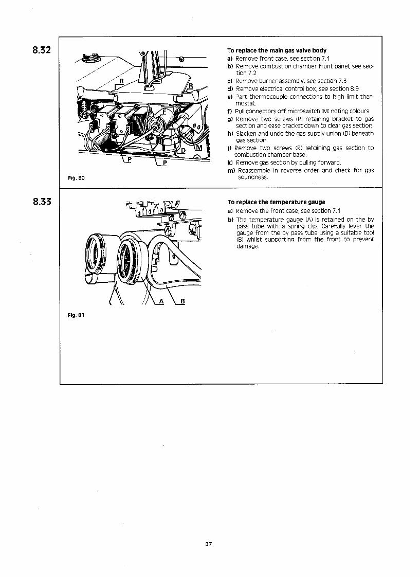
Fig. 80
To replace the main gas valve body a) Remove front case, see section 7.1 bl Remove combustion chamber front panel, see sec-
tion 7.2 c) Remove burner assembly, see section 7.3 d) Remove electrical control box, see section 8.9 e) Part thermocouple connections to high limit ther-
mostat. f) Pull connectors off microswitch (MI noting colours. g) Remove two screws (P) retaining bracket to gas
section and ease bracket down to clear gas section. h) Slacken and undo the gas supply union (D) beneath
gas section. j) Remove two screws (R) retaining gas section to
combustion chamber base. k) Remove gas section by pulling forward. m) Reassemble in reverse order and check for gas
soundness.
To replace the temperature gauge a) Remove the front case, see section 7.1 b) The temperature gauge (A) is retained on the by
pass tube with a spring clip Carefully lever the gauge from the by pass tube using a suitable tool (B) whilst supporting from the front to prevent damage.
Fig. 81
37

9. FAULT FINDING
9.1 logic sequence
I electrical supply I
summer I winter
1r
1r
yes L LA yes 4 I‘
no
no
+ time delay purge
combustion chamber +
1 spark I
+ check low speed
+
no
no
1r no
Yes
zero volts check
AL
+
1st stage solenoid open I 1st stage solenoid open I
time delay 5 sec. max. time delay 5 sec. max.
+ 2nd stage solenoid opens I 2nd stage solenoid opens - I
38

9.2 FAULT FINDING CENTRAL HEATING OPERATION
SEQUENTIAL FLOW CHART 1 READ IN CONJUNCTION WITH SECTIONS (9.1 & 9.3)
Check
START il System water pressure - 1 bar
ii) Gas cock open gas lines PUT- w-d
set selector switch to central heating and hot water.
Check il External controls in demand
mode. iii) Electrical supply switched on.
c I
IS 240 V a.c. across red and brown wires on fan connector on PCB.
Check electrode lead connected to rear of electrical box. Check electro- de and lead for physical damage. Is 240V a.~. across red and blue igniter connection on printed circuit board.
Isolate supply is there continuity to pressure switch between two
Check external fuse and/or rectify
Check connections to main switch.
iii) Pilot injector is clean
il Position of ii, CA.-,+ kn-rl
Measure millivolt output at thermo electric valve (TEV) greater than 12
limit thermostat
t I I/ IS output to TN less than 12 mV?
diators valves open. Rectify
Remove plugs from board and check
b) Water flow switch (black leads) cl CH limit stat (black leads) dl CH control stat (red and black
leads) Is there ContinuitV across all compo- I
39

9.3 FAULT FINDING
START
T
Open
I:: hot water tap
DOMESTIC WATER OPERATION SEQUENTIAL FLOW CHART 2
READ IN CONJUNCTION WITH SECTIONS (9.1 & 9.2)
1 END
Ensure microswitch is made.
yes
Is there continuity across domestic hot water thermostat ?
ii4L?l Ensure water inlet pressure greater
Check inlet filter and venturi for Fl Ensure all isolating valves and stop
Check diaphragm is OK.
Replace if necessary.
40

9.4 FAULT FINDING TABULAR CHART
PROBLEM CAUSE REMEDY
1 Explosive ignition i) Poor pilot flame a) Inlet pressure low - should be 8” wg
(20 mbar) working pressure b) Blocked gas filter c) Pilot injector dirty
ii) l/3 valve not operating a) 24 volt supply to valve bl No voltage at solenoid
la) Check meter and pipe sizing, see sections 2.7 and 4.7.
lb) Clean ICI Replace, see section 8.29
2al Replace solenoids, see section 8.20 2b) Check plugs on printed circuit board 2~) Replace printed circuit board,
see section 8.18
iii) Crosslighting strip - missing/incorrectly positioned.
3a) Replace or reposition.
!I Unstable burner i) Incorrect injectors I) Replace manifold 1.28 mm injectors for natural gas, see section 8.28
ii) Gas pressure at manifold a) Too high b) Too low
2a) Adjust, see section 6.4 2b) Check restrictors and inlet pressure,
see section 1.2
iii) Terminal incorrectly positioned
iv) Incorrectly assembled flue duct
3) See section 2.4
4) Check and reassemble, see section 4.10
VI Fan incorrectly located 5) Remove and refit correctly, see section 8.22
vi) Combustion chamber front cover not sealing 6a) Tighten 5b) Replace sealing strip
vii) Heat exchanger fins blocked 7) Clean, see section 7.2 et 7.7.
viii) Neoprene gasket in turret not correctly fitted 8) Fit or refit, see section 4.10. or missing
I) Central heating - low flow temperature
i) Boiler thermostat out of calibration
ii) Limit stat out of calibration
iii) Insufficient gas pressure
I) Replace, see section 8.14
2) Replace, see section 8.15
3) Check pressure at meter and pipe sizing, see sections 2.7 and 4.7
iv) I/3 blue or 2/3 orange gas valve not opening a) 24 volts at solenoid. 4a) Replace solenoid, see section 8.20 b) No voltage at solenoid 4b) Replace printed circuit board,
see section 8.18
VI Hot water valve in change over valve assembly sticking a) Dead leg on hot water system 5a) Eliminate b) Bent spindle in valve 5b) Replace, see section 8.11
vi) By-pass, if fitted, incorrectly adjusted 6) Adjust, see section 3.16
vii) Pressure switch hunting 7) Replace, see section 8.23
41

PROBLEM CAUSE REMEDY
I) Boiler noisy i) On heating only a) Low flow rate as result of system resistance la) Check and if omitted fit by-pass
see section 3.16 b) Air in system lb) Purge by venting radiators
ii) On hot water and central heating a) Low pressure in sealed system 2a) Repressurise tp 1 bar cold,
see section 6.2 (5) b) Pump not running 2bl Replace pump head, see section 8.10
iii) Blocked filter on heating return 3) Clean and replace, see section 7.6 iv) GaS filter fitted t0 heating flow or retUrn pipes 4) Remove and reposition,
see section 4.5 v) Heat exchanger scaled 5a) Descale
5b) Replace, see section 8.8 vi) Overgassed 6al Check gas pressure and adjust,
see section 6.4 6b) Check restrictors, see section I .2
(VII) Isolating valves not fully oper I 7) Open fully see section 6.2
5) Hot water does not i) Water govenor sticking 11 Lubricate and replace, operate over see section 7.5 temperature range ii) Low inlet water pressure 2) Ensure all down stream
stop cocks open iii) Inlet water filter blocked 3) Clean and replace, see section 7.5 iv) Incorrect venturi fitted 4) Replace with 5.4 mm diameter,
see section 8.7 v) Hot water limit stat out of calibration 5) Replace, see section 8.16
vi) Solenoids not operating 6) See section 9.2. Flow chart 1 vii) Pressure switch hunting 7) Replace, see section 8.23
viii) Low inlet gas pressure 8) See section 6.4
5) No main burner
7) Safety valve discharges
i) Lack of water flow
ii) Pump jammed iii) No water iv) Flow switch not operating v) Heating thermostat faulty (CH only)
i) System pressure too high ii) Not isolated from mains
iii) Vessel lost air charge
1) Checks valves are open, see sections 6.1 and 6.2
2) Manually check, see section 6.2 (8) 3) Fill system, see section 6.2 4) Replace switch, see section 8.34 5) Replace see section 8.14
I) Adjust to 1 bar cold 2) Remove filling loop 3) Recharge to 0.65 bar,
see section 8.24 iv) Secondary heat exchanger (water to water).
Internal water leak. 4) Replace, see section 8.12
3) Pump noisy i) Air in system ii) Air seperator not venting
a) Needle stuck b) Float stuck
iii) Debris in pump iv) Water filter blocked.
I) Vent radiators 2) Open vent on air separator,
see section 6.2 (4) 2a) Release and lubricate 2b) Release and lubricate 3) Clean and replace, see section 8.10 4) Clean and replace, !ee section 7.6
42

PROBLEM CAUSE REMEDY
9) Excessive temperature rise across boiler
i) Return filter blocked
ii) Low water flow rate a) Pump defective b) High system resistance c) Gas filter inadvertantly fitted in flow
or return connection
iii) Gas rate too high
I) Clean and replace, see section 7.6
2a) Replace, see section 8.10 2b) Fit by-pass, see section 3.16 2~) Remove and refit, see section 4.5
3) Adjust, see section 6.4
10) Rapid cycling high/low or high/low/off
i) Low water flow rate
ii) Limit stat out of calibration
iii) By-pass if fitted not regulated
iv) Blocked heat exchanger
I) See ‘System guidance’ section 3.3
2) Replace, see section 8.15
3) Adjust, see section 6.5
4) Clean or replace, see section 8.8
11) Fan on high speed continuously
i) Defective printed circuit board I) Replace, see section 8.18
12) Lossofpressure shown on gauge
i) Leak on system
ii) Leak on appliance
I) Locate and rectify
2) Locate and rectify
13) Gain in pressure shown on gauge
i) Filling loop still fitted and letting by I) Close stop cocks and remove
ii) Blockage in expansion chamber flexible hose 2) Clear blockage
iii) Secondary heat exchanger (water to water). 3) Replace, see section 8.12 Internal water leak
43
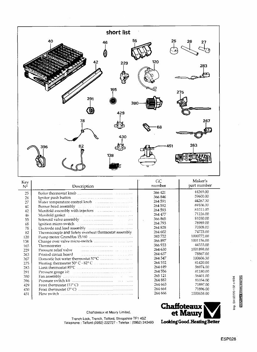
?O A 46
short list
380
283
78 & 267 - *’
0 0 68
Key N”
25 26 27 40 42 46 55 68 78 82
120 138 165 229 263 267 275 283 291 380 396 429 430 451
Descridion
Boiler thermostat knob ............................................ Ignitor push button ............................................ Water temperature control knob .............................. Burner head assembly ........................................ Manifold assembly with injectors ............................ Manifold gasket ................................................... Solenoid valve assembly ........................................ Ignition micro-switch ......................................... Electrode and lead assembly ................................... Thermocouple and Safety overheat thermostat assembly Pump motor Grundfos 15/60 ................................... Change over valve micro-switch ............ .................. Thermometer ........................................................ Pressure relief valve ............................................... Printed circuit board ..................................... Domestic hot water thermostat 57°C .......................... Heating thermostat 50” C - 82” C .......................... Limit thermostat 85°C ............................................. Pressure gauge kit .......................................... Fan assembly ....................................... ..... ....... Pressure switch kit ............................................ Frost thermostat (ll” C) ......................................... Frost thermostat (3” C) ............................................ Flow switch ....................................................
Chaffoteaux et Maury Limited,
GC number
366421 366846 264591 264592 264593 264477 366865 264793 264828 264602 383722 366897 366933 264630 264637 264547 264552 264649 264556 265121 264882 264663 264664 264666
Trench Lock, Trench, Telford, Shropshire TFl 4SZ Telephone : Telford (0952) 222727 - Telefax : (0952) 243493
Maker’s part number
44269.00 59600.00 44267.00 69106.00 81011.00 71226.00 81030.00 78989.00 70308.00 74723.00
1000772.00 1001156.00
44333.00 1001898.00
78867.00 100606.30 81420.00 56974.00 81180.00 56401.00 81054.00 71897.00 71896.00
1000658.00
ESP028