ceiec pmc-43 series - cet.dyndns-ip.comcet.dyndns-ip.com/products/user-manual/meters/pmc-53 series...
TRANSCRIPT

PMC-53 Series Intelligent Multifunction Meter
User Manual
Version: V5.2A
02/07/2012
Ceiec Electric Technology

Ceiec Electric Technology
2
This manual may not be reproduced in whole or in part by any means without the express
written permission from Ceiec Electric Technology (CET).
The information contained in this manual is believed to be accurate at the time of
publication; however, CET assumes no responsibility for any errors which may appear here
and reserves the right to make changes without notice. Please consult CET or your local
representative for the latest product specifications.
Standards Compliance
DANGER
This symbol indicates the presence of danger that may result in severe injury or death and
permanent equipment damage if proper precautions are not taken during the installation,
operation or maintenance of the device.
CAUTION
This symbol indicates the potential of personal injury or equipment damage if proper
precautions are not taken during the installation, operation or maintenance of the device.

Ceiec Electric Technology
3
DANGER Failure to observe the following instructions may result in severe injury or
death and/or equipment damage.
Installation, operation and maintenance of the meter should only be
performed by qualified, competent personnel that have the appropriate
training and experience with high voltage and current devices. The meter
must be installed in accordance with all local and national electrical codes.
Ensure that all incoming AC power and other power sources are turned OFF
before performing any work on the meter.
Before connecting the meter to the power source, check the label on top of
the meter to ensure that it is equipped with the appropriate power supply,
and the correct voltage and current input specifications for your application.
During normal operation of the meter, hazardous voltages are present on its
terminal strips and throughout the connected potential transformers (PT) and
current transformers (CT). PT and CT secondary circuits are capable of
generating lethal voltages and currents with their primary circuits energized.
Follow standard safety precautions while performing any installation or
service work (i.e. removing PT fuses, shorting CT secondaries, …etc).
Do not use the meter for primary protection functions where failure of the
device can cause fire, injury or death. The meter should only be used for
shadow protection if needed.
Under no circumstances should the meter be connected to a power source if
it is damaged.
To prevent potential fire or shock hazard, do not expose the meter to rain or
moisture.
Setup procedures must be performed only by qualified personnel familiar
with the instrument and its associated electrical equipment.
DO NOT open the instrument under any circumstances.

Ceiec Electric Technology
4
Limited warranty
Ceiec Electric Technology (CET) offers the customer a minimum of 12-month
functional warranty on the meter for faulty parts or workmanship from the date
of dispatch from the distributor. This warranty is on a return to factory for
repair basis.
CET does not accept liability for any damage caused by meter malfunctions.
CET accepts no responsibility for the suitability of the meter to the application
for which it was purchased.
Failure to install, set up or operate the meter according to the instructions
herein will void the warranty.
Only CET’s duly authorized representative may open your meter. The unit
should only be opened in a fully anti-static environment. Failure to do so may
damage the electronic components and will void the warranty.

Ceiec Electric Technology
5
Table of Contents
Chapter 1 Introduction ............................................................................................................................ 7
1.1 Overview .................................................................................................................................... 7
1.2 Features ...................................................................................................................................... 7
1.3 PMC-53 series’ application in Power and Energy Management Systems ................................... 9
1.4 Getting more information ........................................................................................................ 10
Chapter 2 Installation ............................................................................................................................ 11
2.1 Appearance .............................................................................................................................. 11
2.2 Unit Dimensions ....................................................................................................................... 12
2.3 Mounting .................................................................................................................................. 12
2.4 Wiring connections .................................................................................................................. 13
2.4.1 3-phase 4-wire Wye Direct Connection ........................................................................ 13
2.4.2 3-phase 4-wire Wye with 3PTs and 3CTs ....................................................................... 14
2.4.3 3-phase 3-wire Open Delta Direct Connection ............................................................. 14
2.4.4 3-phase 3-wire Open Delta with 2PTs and 3CTs ............................................................ 15
2.4.5 3-phase 3-wire Open Delta with 2PTs and 2CTs ............................................................ 15
2.5 Communications Wiring ........................................................................................................... 16
2.6 Digital Input Wiring .................................................................................................................. 16
2.7 Digital Output Wiring ............................................................................................................... 16
2.8 Pulse Output Wiring ................................................................................................................. 17
2.9 I residual Input Wiring .............................................................................................................. 17
2.10 Temperature Input Wiring ...................................................................................................... 17
2.11 Power Supply Wiring .............................................................................................................. 17
Chapter 3 Front Panel ............................................................................................................................ 18
3.1 LCD Display ............................................................................................................................... 18
3.1.1 LCD Testing .................................................................................................................... 18
3.1.2 LCD Display Areas .......................................................................................................... 18
3.1.3 Peak Demand Display .................................................................................................... 20
3.2 LED Indicators ........................................................................................................................... 20
3.3 Display Screen Types ................................................................................................................ 20
3.3.1 Default Screen ............................................................................................................... 21
3.3.2 Data Display .................................................................................................................. 21
3.4 Setup Configuration via the Front Panel .................................................................................. 22
3.4.1 Functions of buttons ..................................................................................................... 22
3.4.2 Reset the Alarm LED and Buzzer ................................................................................... 23
3.4.3 Setup Menu .................................................................................................................. 24
3.4.4 Configuration ................................................................................................................ 25
Chapter 4 Applications .......................................................................................................................... 30
4.1 Inputs and Outputs................................................................................................................... 30
4.1.1 Digital Inputs ................................................................................................................. 30
4.1.2 Digital Outputs .............................................................................................................. 30
4.1.3 Energy Pulse Outputs .................................................................................................... 31
4.1.4 I residual Input .............................................................................................................. 31

Ceiec Electric Technology
6
4.1.5 Temperature Input ........................................................................................................ 32
4.2 Power and Energy .................................................................................................................... 32
4.2.1 Voltage and Current Phase Angles ................................................................................ 32
4.2.2 Energy ........................................................................................................................... 32
4.2.3 Demands ....................................................................................................................... 33
4.3 Setpoints .................................................................................................................................. 33
4.3.1 Control Setpoints .......................................................................................................... 33
4.3.2 Digital Input Setpoints................................................................................................... 34
4.3.3 I residual Setpoints ........................................................................................................ 35
4.3.4 Temperature Setpoint ................................................................................................... 36
4.4 SOE ........................................................................................................................................... 36
4.5 Power Quality ........................................................................................................................... 37
4.5.1 Harmonics ..................................................................................................................... 37
4.5.2 Unbalance ..................................................................................................................... 37
Chapter 5 Modbus Register Map........................................................................................................... 38
5.1 Basic Measurements ................................................................................................................ 38
5.2 Energy Measurements ............................................................................................................. 40
5.3 Peak Demands .......................................................................................................................... 41
5.4 Harmonic Measurements ......................................................................................................... 41
5.5 Setup Parameters ..................................................................................................................... 42
5.6 SOE Log ..................................................................................................................................... 44
5.7 Time ......................................................................................................................................... 46
5.8 DO Control ................................................................................................................................ 47
5.9 Meter Information .................................................................................................................... 47
Revision History ..................................................................................................................................... 49
Appendix A Technical Specifications ..................................................................................................... 50
Appendix B Residual Current Sensor (Zero Sequence CT) .................................................................... 52
Appendix C Temperature Sensor ........................................................................................................... 54
Appendix D Standards Compliance ....................................................................................................... 55
Appendix E Ordering Guide ................................................................................................................... 56
Contact us .............................................................................................................................................. 56

Ceiec Electric Technology
7
Chapter 1 Introduction
This manual explains how to use the PMC-53 Series Intelligent Multifunction Meter. Throughout the
manual the term “meter” generally refers to all models. Differences between the models are
indicated with the appropriate model number.
This chapter provides an overview of the PMC-53 series meter and summarizes many of its key
features.
1.1 Overview
The PMC-53 Series Intelligent Multifunction Meter is CET’s latest offer for the low-cost digital
power/energy metering market. Housed in an industry standard DIN form factor measuring
96mmx96mmx75mm, it is perfectly suited for industrial, commercial and utility metering applications.
The PMC-53 features quality construction, multifunction measurements and a large, backlit, easy to
read LCD display. Compliance with the IEC 62053-22 Class 0.5S kWh Accuracy Standard, it is a cost
effective replacement for analog instrumentation, capable of displaying 3-phase measurements at
once. It optionally provides two Digital Inputs for status monitoring and two Digital Outputs for
control, alarm or energy pulsing applications. Further, it has optional inputs for I residual as well as
RTD temperature measurements for fire alarm monitoring, transformer temperature monitoring or
other applications. The standard SOE Log records all setup changes, DI/Setpoint status changes and
DO operations in 1ms resolution. With the standard RS485 port and Modbus protocol support, the
PMC-53 becomes a vital component of an intelligent, multifunction monitoring solution for any Power
and Energy Management systems.
You can setup the meter through its front panel or via our free PMC Setup software. The meter is
also supported by our PecStar® Integrated Energy Management System.
The PMC-53 is available in three models: PMC-53V, PMC-53I and PMC-53M. Following is a list of
typical applications for the PMC-53:
Analog meter replacement
Low and medium voltage applications
Industrial and commercial panel metering
Substation, factory and building automation
Sub-metering, cost allocation
Residual Current and Temperature monitoring
Contact CET Technical Support should you require further assistance with your application.
1.2 Features
Enhanced Measurements (Firmware Version V1.20.01 or later)
Neutral Current, Displacement PF
Voltage and Current Unbalance, THD and K-Factor
kW Total, kvar Total, kVA Total and Current Demands/Peak Demands
Voltage and Current Phase Angles

Ceiec Electric Technology
8
Ease of use
Large, backlit, easy to read, 5-line LCD display with wide viewing angle
Password-protected setup via front panel or free PMC Setup software
Easy installation with mounting clips, no tools required
Built in alarm buzzer for optional I residual and Temperature alarms
Setpoints
6 user programmable setpoints
Configurable thresholds, time delays and DO triggers
SOE Log
32 events time-stamped to ±1ms resolution
Setup changes, Setpoint and DI status changes and DO operations
Communications
Optically isolated RS485 port
Selectable baud rate from 1200 bps to 19,200 bps
Modbus RTU protocol
System Integration
Supported by our PecStar® Integrated Energy Management System
Easy integration into other Automation or SCADA systems
Optional features
I residual Input (Residual Current)
Requires an optional, external Zero Sequence CT (1A nominal)
Two levels of alarm – ALARM and TRIP. Each alarm level:
Can be enabled individually
Programmable threshold and time delay
Logs an SOE event, sounds the alarm buzzer AND triggers a dedicated DO when activated
RTD Temperature Input
Requires an optional, external RTD temperature probe
Programmable threshold and time delay
Logs an SOE event, sounds the alarm buzzer AND triggers a dedicated DO when activated
Digital Inputs and Outputs
Digital Inputs – 2 volts free dry contact, 24VDC internally wetted
Digital Outputs – 2 Form A DO (mechanical) or Solid State (SS) relays
2 DO relays
DO1 is for I residual or Temperature ALARM output if present AND enabled
DO2 is for I residual TRIP output if present AND enabled
2 SS relays for kWh and kvarh pulsing
Ceiec Electric Technology
9
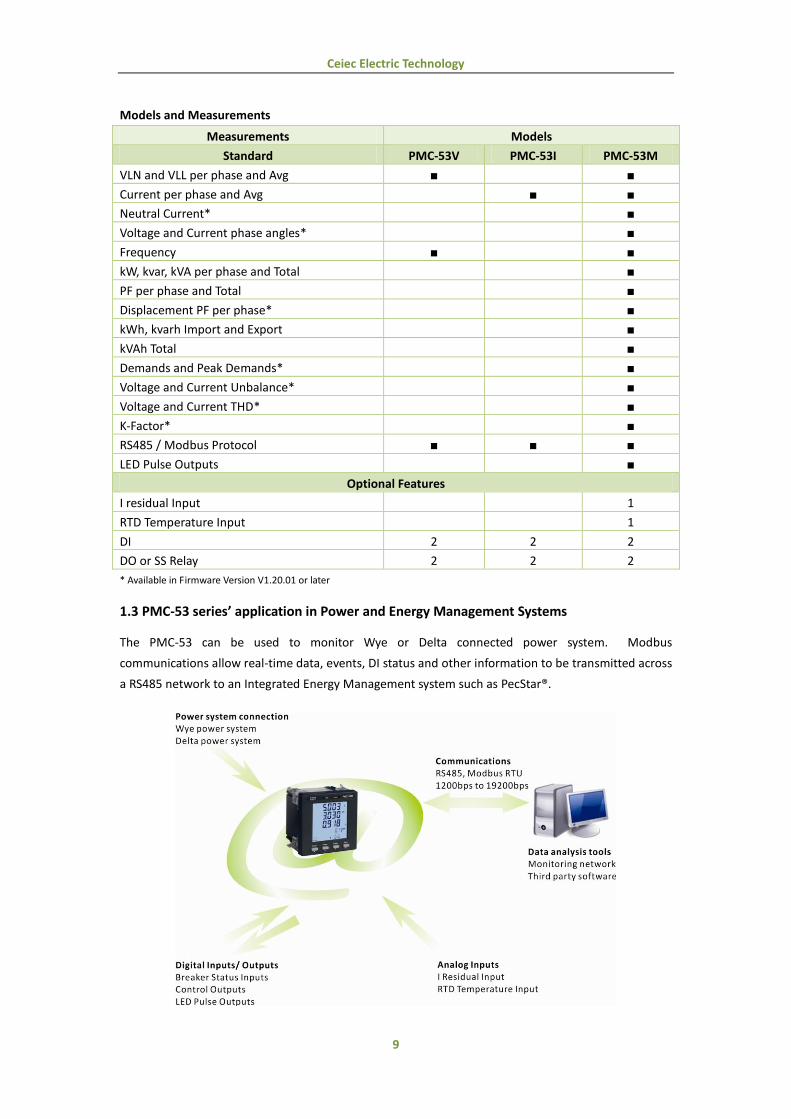
Models and Measurements
Measurements Models
Standard PMC-53V PMC-53I PMC-53M
VLN and VLL per phase and Avg
Current per phase and Avg
Neutral Current*
Voltage and Current phase angles*
Frequency
kW, kvar, kVA per phase and Total
PF per phase and Total
Displacement PF per phase*
kWh, kvarh Import and Export
kVAh Total
Demands and Peak Demands*
Voltage and Current Unbalance*
Voltage and Current THD*
K-Factor*
RS485 / Modbus Protocol
LED Pulse Outputs
Optional Features
I residual Input 1
RTD Temperature Input 1
DI 2 2 2
DO or SS Relay 2 2 2
* Available in Firmware Version V1.20.01 or later
1.3 PMC-53 series’ application in Power and Energy Management Systems
The PMC-53 can be used to monitor Wye or Delta connected power system. Modbus
communications allow real-time data, events, DI status and other information to be transmitted across
a RS485 network to an Integrated Energy Management system such as PecStar®.

Ceiec Electric Technology
10
1.4 Getting more information
Additional information is available from CET via the following sources:
Visit www.ceiec-electric.com
Contact your local representative
Contact CET directly via email or telephone

Ceiec Electric Technology
11
Chapter 2 Installation
2.1 Appearance
Figure 2-1 Appearance
Caution
Installation of the PMC-53 should only be performed by qualified, competent personnel
that have the appropriate training and experience with high voltage and current devices.
The meter must be installed in accordance with all local and national electrical codes.
During the operation of the meter, hazardous voltages are present at the input terminals.
Failure to observe precautions can result in serious or even fatal injury and equipment
damage.

Ceiec Electric Technology
12
2.2 Unit Dimensions
Figure 2-2 Dimensions
2.3 Mounting
The PMC-53 series meter should be installed in a dry environment with no dust and kept away from
heat, radiation and electrical noise source.
Installation steps:
Remove the installation clips from the meter
Fit the meter through a 92mmx92mm cutout as shown in Figure 2-3
Re-install the installation clips and push the clips tightly against the panel to secure the meter
Figure 2-3 Panel Cutout

Ceiec Electric Technology
13
2.4 Wiring connections
PMC-53 can satisfy almost any three phase power systems. Please read this section carefully before
installation and choose the correct wiring method for your power system. The following Wiring
Modes are supported:
3-phase 4-wire Wye Direct Connection
3-phase 4-wire Wye with 3PTs and 3CTs
3-phase 3-wire open Delta Direct Connection
3-phase 3-wire open Delta with 2PTs and 3CTs.
3-phase 3-wire open Delta with 2PTs and 2CTs
2.4.1 3-phase 4-wire Wye Direct Connection
Please consult the serial number label to ensure that the system phase voltage is less than or equal to
the meter’s voltage input specification.
Set the Wiring Mode to Wye.
Figure 2-4 4-Wire Wye, Direct Connection
Caution
Under no circumstances should the PT secondary be shorted.
Under no circumstances should the CT secondary be open when the CT primary is
energized. CT shorting blocks should be installed to allow for easy maintenance.
Ceiec Electric Technology
14
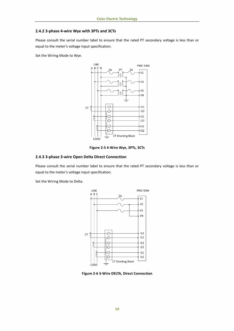
2.4.2 3-phase 4-wire Wye with 3PTs and 3CTs
Please consult the serial number label to ensure that the rated PT secondary voltage is less than or
equal to the meter’s voltage input specification.
Set the Wiring Mode to Wye.
Figure 2-5 4-Wire Wye, 3PTs, 3CTs
2.4.3 3-phase 3-wire Open Delta Direct Connection
Please consult the serial number label to ensure that the rated PT secondary voltage is less than or
equal to the meter’s voltage input specification.
Set the Wiring Mode to Delta.
Figure 2-6 3-Wire DELTA, Direct Connection
Ceiec Electric Technology
15
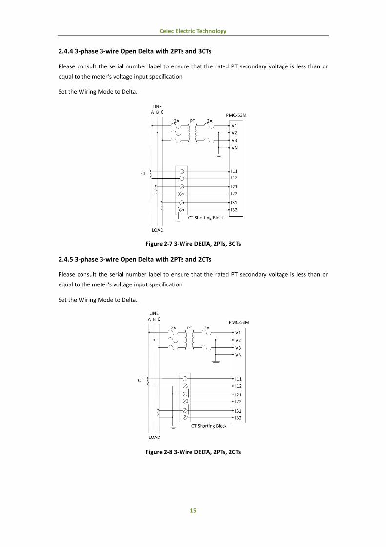
2.4.4 3-phase 3-wire Open Delta with 2PTs and 3CTs
Please consult the serial number label to ensure that the rated PT secondary voltage is less than or
equal to the meter’s voltage input specification.
Set the Wiring Mode to Delta.
Figure 2-7 3-Wire DELTA, 2PTs, 3CTs
2.4.5 3-phase 3-wire Open Delta with 2PTs and 2CTs
Please consult the serial number label to ensure that the rated PT secondary voltage is less than or
equal to the meter’s voltage input specification.
Set the Wiring Mode to Delta.
Figure 2-8 3-Wire DELTA, 2PTs, 2CTs

Ceiec Electric Technology
16
2.5 Communications Wiring
The following figure illustrates the RS485 communications connections on the PMC-53:
Figure 2-9 Communications Connections
The PMC-53 provides one RS485 port and supports the Modbus RTU protocol. Up to 32 devices can
be connected on a RS485 bus. The overall length of the RS485 cable connecting all devices should
not exceed 1200m.
If the master station does not have a RS485 communications port, a RS232/RS485 or USB/RS485
converter with optically isolated output and surge protection should be used.
2.6 Digital Input Wiring
The following figure illustrates the Digital Input connections on the PMC-53:
Figure 2-10 DI Connections
2.7 Digital Output Wiring
The following figure illustrates the Digital Output connections on the PMC-53:
Figure 2-11 DO Connections
Ceiec Electric Technology
17
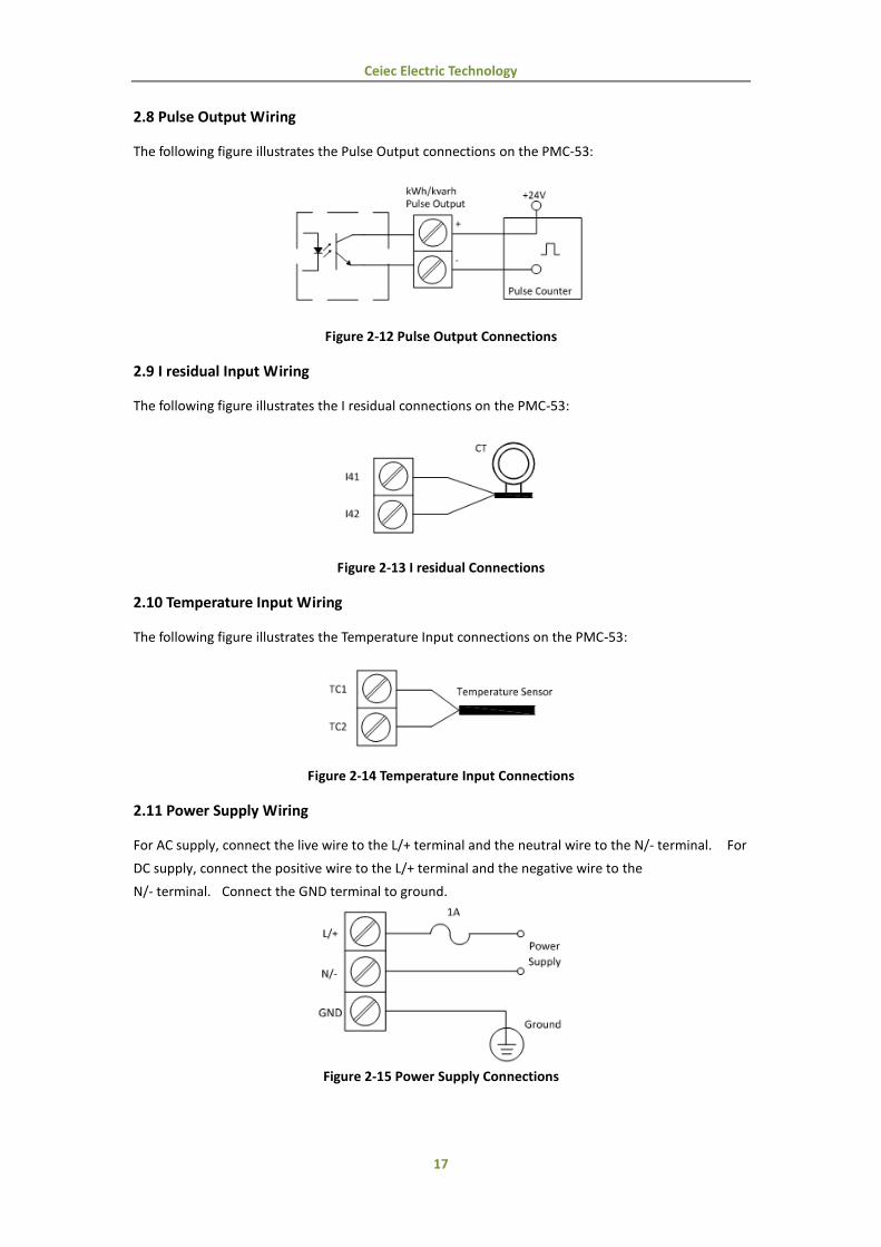
2.8 Pulse Output Wiring
The following figure illustrates the Pulse Output connections on the PMC-53:
Figure 2-12 Pulse Output Connections
2.9 I residual Input Wiring
The following figure illustrates the I residual connections on the PMC-53:
Figure 2-13 I residual Connections
2.10 Temperature Input Wiring
The following figure illustrates the Temperature Input connections on the PMC-53:
Figure 2-14 Temperature Input Connections
2.11 Power Supply Wiring
For AC supply, connect the live wire to the L/+ terminal and the neutral wire to the N/- terminal. For
DC supply, connect the positive wire to the L/+ terminal and the negative wire to the
N/- terminal. Connect the GND terminal to ground.
Figure 2-15 Power Supply Connections
Ceiec Electric Technology
18
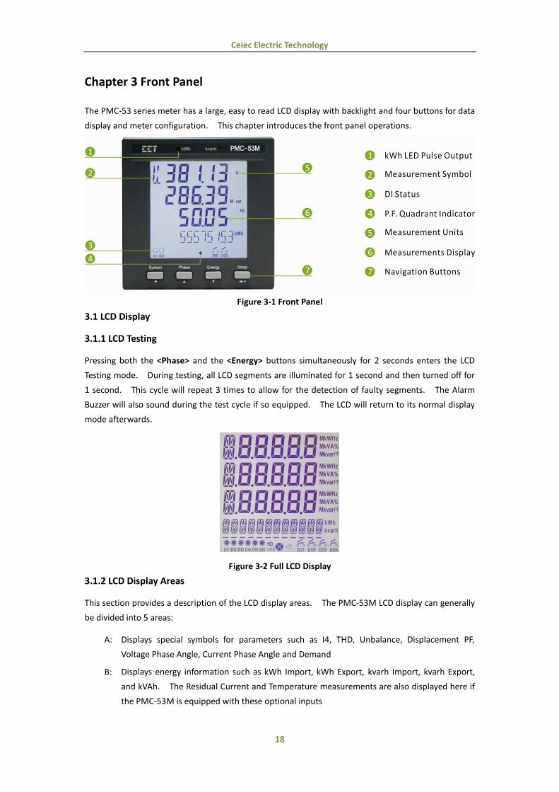
Chapter 3 Front Panel
The PMC-53 series meter has a large, easy to read LCD display with backlight and four buttons for data
display and meter configuration. This chapter introduces the front panel operations.
Figure 3-1 Front Panel
3.1 LCD Display
3.1.1 LCD Testing
Pressing both the <Phase> and the <Energy> buttons simultaneously for 2 seconds enters the LCD
Testing mode. During testing, all LCD segments are illuminated for 1 second and then turned off for
1 second. This cycle will repeat 3 times to allow for the detection of faulty segments. The Alarm
Buzzer will also sound during the test cycle if so equipped. The LCD will return to its normal display
mode afterwards.
Figure 3-2 Full LCD Display
3.1.2 LCD Display Areas
This section provides a description of the LCD display areas. The PMC-53M LCD display can generally
be divided into 5 areas:
A: Displays special symbols for parameters such as I4, THD, Unbalance, Displacement PF,
Voltage Phase Angle, Current Phase Angle and Demand
B: Displays energy information such as kWh Import, kWh Export, kvarh Import, kvarh Export,
and kVAh. The Residual Current and Temperature measurements are also displayed here if
the PMC-53M is equipped with these optional inputs

Ceiec Electric Technology
19
C: Displays the indicators for DI status, DO status, Harmonic Distortion (HD), Unbalance (unb),
PF Quadrant and Alarm status
D: Displays Measurement values
E: Displays Measurement Units
Figure 3-3 LCD Display
The following table shows the special LCD display symbols:
Area Segments Symbol Description
A
Phase Voltage
Line Voltage
I4
Voltage/Current Unbalance
Demand
Displacement PF
Va/Vb/Vc THD
Ia/Ib/Ic THD
K-Factor
Va/Vb/Vc Angle
Ia/Ib/Ic Angle
B
kVAh Indicator
kWh/kvarh Export Indicator
C
DI Open
DI Close
DO Open
DO Close
Harmonic
Distortion
Unbalance
PF Quadrant
Alarm Symbol
Table 3-1 Special LCD Display Symbols
Ceiec Electric Technology
20
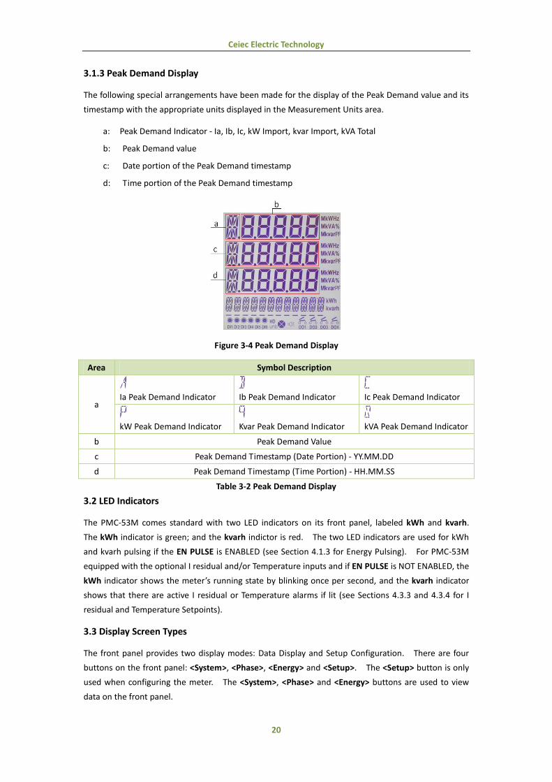
3.1.3 Peak Demand Display
The following special arrangements have been made for the display of the Peak Demand value and its
timestamp with the appropriate units displayed in the Measurement Units area.
a: Peak Demand Indicator - Ia, Ib, Ic, kW Import, kvar Import, kVA Total
b: Peak Demand value
c: Date portion of the Peak Demand timestamp
d: Time portion of the Peak Demand timestamp
Figure 3-4 Peak Demand Display
Area Symbol Description
a
Ia Peak Demand Indicator
Ib Peak Demand Indicator
Ic Peak Demand Indicator
kW Peak Demand Indicator
Kvar Peak Demand Indicator
kVA Peak Demand Indicator
b Peak Demand Value
c Peak Demand Timestamp (Date Portion) - YY.MM.DD
d Peak Demand Timestamp (Time Portion) - HH.MM.SS
Table 3-2 Peak Demand Display
3.2 LED Indicators
The PMC-53M comes standard with two LED indicators on its front panel, labeled kWh and kvarh.
The kWh indicator is green; and the kvarh indictor is red. The two LED indicators are used for kWh
and kvarh pulsing if the EN PULSE is ENABLED (see Section 4.1.3 for Energy Pulsing). For PMC-53M
equipped with the optional I residual and/or Temperature inputs and if EN PULSE is NOT ENABLED, the
kWh indicator shows the meter’s running state by blinking once per second, and the kvarh indicator
shows that there are active I residual or Temperature alarms if lit (see Sections 4.3.3 and 4.3.4 for I
residual and Temperature Setpoints).
3.3 Display Screen Types
The front panel provides two display modes: Data Display and Setup Configuration. There are four
buttons on the front panel: <System>, <Phase>, <Energy> and <Setup>. The <Setup> button is only
used when configuring the meter. The <System>, <Phase> and <Energy> buttons are used to view
data on the front panel.
Ceiec Electric Technology
21
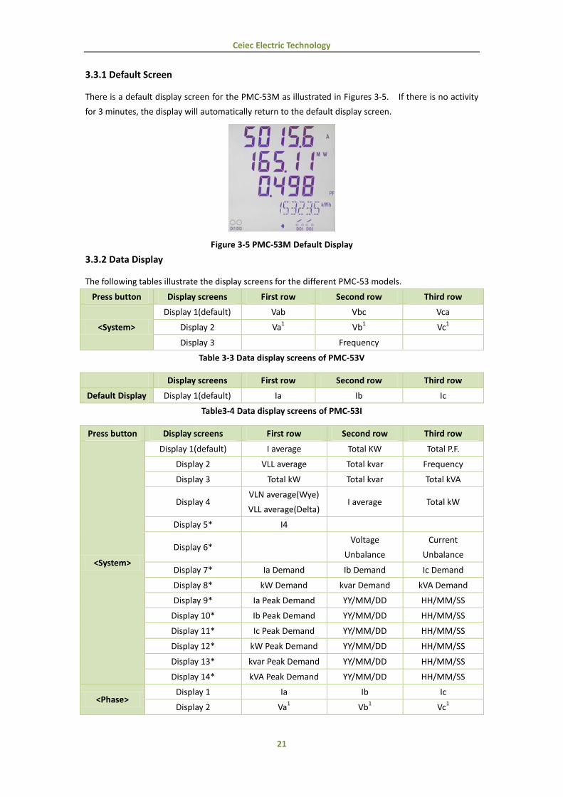
3.3.1 Default Screen
There is a default display screen for the PMC-53M as illustrated in Figures 3-5. If there is no activity
for 3 minutes, the display will automatically return to the default display screen.
Figure 3-5 PMC-53M Default Display
3.3.2 Data Display
The following tables illustrate the display screens for the different PMC-53 models.
Press button Display screens First row Second row Third row
<System>
Display 1(default) Vab Vbc Vca
Display 2 Va1 Vb
1 Vc
1
Display 3 Frequency
Table 3-3 Data display screens of PMC-53V
Display screens First row Second row Third row
Default Display Display 1(default) Ia Ib Ic
Table3-4 Data display screens of PMC-53I
Press button Display screens First row Second row Third row
<System>
Display 1(default) I average Total KW Total P.F.
Display 2 VLL average Total kvar Frequency
Display 3 Total kW Total kvar Total kVA
Display 4 VLN average(Wye)
VLL average(Delta) I average Total kW
Display 5* I4
Display 6* Voltage
Unbalance
Current
Unbalance
Display 7* Ia Demand Ib Demand Ic Demand
Display 8* kW Demand kvar Demand kVA Demand
Display 9* Ia Peak Demand YY/MM/DD HH/MM/SS
Display 10* Ib Peak Demand YY/MM/DD HH/MM/SS
Display 11* Ic Peak Demand YY/MM/DD HH/MM/SS
Display 12* kW Peak Demand YY/MM/DD HH/MM/SS
Display 13* kvar Peak Demand YY/MM/DD HH/MM/SS
Display 14* kVA Peak Demand YY/MM/DD HH/MM/SS
<Phase> Display 1 Ia Ib Ic
Display 2 Va1 Vb
1 Vc
1

Ceiec Electric Technology
22
Display 3 Vab Vbc Vca
Display 4 kWa1 kWb
1 kWc
1
Display 5 kvara1 kvarb
1 kvarc
1
Display 6 kVAa1 kVAb
1 kVAc
1
Display 7 P.F.a1 P.F.b
1 P.F.c
1
Display 8* dP.F.a1 dP.F.b
1 dP.F.c
1
Display 9* Va THD Vb THD Vc THD
Display 10* Ia THD Ib THD Ic THD
Display 11* Ia K-Factor Ib K-Factor Ic K-Factor
Display 12* Va Angle Vb Angle Vc Angle
Display 13* Ia Angle Ib Angle Ic Angle
<Energy>
Display 1 kWh Import
Display 2 kWh Export
Display 3 kvarh Import
Display 4 kvarh Export
Display 5 KVAh
Display 6 I residual2
Display 7 Temperature3
* Available in Firmware Version V1.20.01 or later
Table 3-5 Data display screens of PMC-53M
Notes:
1) When connected in Delta mode, the meter displays “-” instead of phase voltages.
2) This display only appears if the meter is equipped with the I residual Input. If the I residual
Sensor is not connected, the display will show N/C.
3) This display only appears if the meter is equipped with the Temperature Input. If the RTD
temperature probe is not connected or if the measured temperature is above 250°C, the display
will show N/C. If the measured temperature is above 200°C and below 250°C, the display will
show OVER, which means the measured value has exceeded the applicable measurement range.
3.4 Setup Configuration via the Front Panel
Pressing the <Setup> button for more than three seconds enters the Setup Configuration mode where
the setup parameters can be changed. Upon completion, pressing the <Setup> button for more than
three seconds returns to the Data Display mode.
3.4.1 Functions of buttons
The four front panel buttons take on different meanings in the Setup Configuration mode and are
described below:
<Setup>: Pressing this button for more than three seconds toggles between Data Display mode
and Setup Configuration mode. Once inside the Setup Configuration mode, pressing
this button selects the parameter for modification. After changing the parameter,
pressing this button again saves the new setting into memory.

Ceiec Electric Technology
23
<Phase>: Before a parameter is selected for modification, pressing this button advances to the
next parameter in the menu. If a parameter is already selected, pressing this button
increments a numeric value or advances to the next value in the selection list.
<Energy>: Before a parameter is selected for modification, pressing this button goes back to the last
parameter in the menu. If a parameter is already selected, pressing this button
decrements a numeric value or goes back to the last value in the selection list.
<System>: Pressing this button moves the cursor to the left by one position if the parameter being
changed is a numeric value. Otherwise, this button is ignored.
Making setup changes:
Press the <Setup> button for more than 3 seconds to access Setup Configuration mode.
Press the <Phase> button to advance to the Password page.
A correct password must be entered before changes are allowed. The factory default
password is zero. Press the <Setup> button to select the parameter for modification. Use
the <System>, <Phase> and <Energy> buttons to enter the correct password.
Selecting a parameter to change:
Use the <Phase> and <Energy> button to scroll to the desired parameter.
Press the <Setup> button to select the parameter. Once selected, the parameter value will
blink.
Changing and saving a parameter:
Use the <System>, <Phase> and <Energy> buttons to make modification to the selected
parameter.
After modification, press the <Setup> button to save the new value into memory.
Returning to Data Display mode:
Pressing the <Setup> button for more than three seconds to return to the default display
screen.
3.4.2 Reset the Alarm LED and Buzzer
If the PMC-53 is equipped with the Alarm Buzzer, the I residual and/or Temperature inputs, the
<System> and <Phase> buttons are implemented with additional functions.
<System>: Pressing this button for 3 seconds resets the Alarm LED and Buzzer after the I residual
and/or Temperature ALARM Setpoint has become inactive.
<Phase>: Pressing this button for 3 seconds mutes the Alarm Buzzer while the I residual and/or
Temperature ALARM Setpoint is active.

Ceiec Electric Technology
24
3.4.3 Setup Menu
Figure 3-6 Setup Menu
Ceiec Electric Technology
25
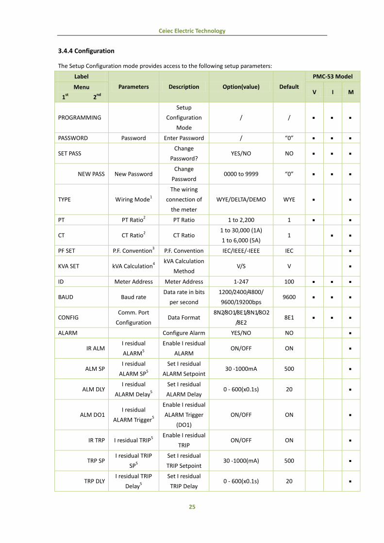
3.4.4 Configuration
The Setup Configuration mode provides access to the following setup parameters:
Label
Parameters Description Option(value) Default
PMC-53 Model
Menu
1st
2nd
V I M
PROGRAMMING
Setup
Configuration
Mode
/ /
PASSWORD Password Enter Password / “0”
SET PASS Change
Password? YES/NO NO
NEW PASS New Password Change
Password 0000 to 9999 “0”
TYPE Wiring Mode1
The wiring
connection of
the meter
WYE/DELTA/DEMO WYE
PT PT Ratio2 PT Ratio 1 to 2,200 1
CT CT Ratio2 CT Ratio
1 to 30,000 (1A)
1 to 6,000 (5A) 1
PF SET P.F. Convention3 P.F. Convention IEC/IEEE/-IEEE IEC
KVA SET kVA Calculation4
kVA Calculation
Method V/S V
ID Meter Address Meter Address 1-247 100
BAUD Baud rate Data rate in bits
per second
1200/2400/4800/
9600/19200bps 9600
CONFIG Comm. Port
Configuration Data Format
8N2/8O1/8E1/8N1/8O2
/8E2 8E1
ALARM Configure Alarm YES/NO NO
IR ALM I residual
ALARM5
Enable I residual
ALARM ON/OFF ON
ALM SP I residual
ALARM SP5
Set I residual
ALARM Setpoint 30 -1000mA 500
ALM DLY I residual
ALARM Delay5
Set I residual
ALARM Delay 0 - 600(x0.1s) 20
ALM DO1 I residual
ALARM Trigger5
Enable I residual
ALARM Trigger
(DO1)
ON/OFF ON
IR TRP I residual TRIP5
Enable I residual
TRIP ON/OFF ON
TRP SP I residual TRIP
SP5
Set I residual
TRIP Setpoint 30 -1000(mA) 500
TRP DLY I residual TRIP
Delay5
Set I residual
TRIP Delay 0 - 600(x0.1s) 20

Ceiec Electric Technology
26
ALM TMP Temperature
ALARM5
Enable
Temperature
ALARM
ON/OFF ON
TMP SP Temperature
ALARM SP5
Set
Temperature
ALARM Setpoint
55 -140(°C) 80
TMP DLY Temperature
ALARM Delay5
Set
Temperature
ALARM Delay
0 - 400(x0.1s) 20
TMP DO1 Temperature
ALARM Trigger5
Set
Temperature
ALARM Trigger
(DO1)
ON/OFF OFF
DI1 PRO DI1 SP Output
Trigger
Enable DI1 SP
Output Trigger OFF/DO1/DO2 OFF
DI2 PRO DI2 SP Output
Trigger
Enable DI2 SP
Output Trigger OFF/DO1/DO2 OFF
DATE Date Enter the
Current Date YY-MM-DD /
CLK Time Enter the
Current Time HH:MM:SS /
SET ENGY Preset Energy
Values
Preset Energy
Values YES/NO NO
kWh kWh Import Preset kWh
Import Value 0 to 99,999,999.9 0
-kWh* kWh Export Preset kWh
Export Value 0 to 99,999,999.9 0
kvarh kvarh Import Preset kvarh
Import Value 0 to 99,999,999.9 0
-kvarh* kvarh Export Preset kvarh
Export Value 0 to 99,999,999.9 0
kVAh kVAh Preset kVAh
Export Value 0 to 99,999,999.9 0
DMD SET* Demand
Parameters
Configure
Demand
Parameters
YES/NO NO
PERIOD Demand
Interval
Set Demand
Interval
1, 2, 3, 5, 10, 15, 30,
60 (minutes) 15
NUM
Number of
Sliding
Windows
Set Number of
Sliding
Windows
1-15 1
EN PULSE Energy Pulsing
Enable kWh and
kvarh Energy
Pulsing
YES/NO NO

Ceiec Electric Technology
27
EN CONST6 Pulse Constant Pulse Constant
1k(1000)/3.2k(3200)/
5k(5000)/6.4k(6400)/
12.8k(12800)
1k
CLR ENGY Clear Energy Clear kWh,
kvarh and kVAh YES/NO NO
CLR DMD* Clear Demand Clear Peak
Demands YES/NO NO
CLR SOE Clear SOE Clear SOE Log YES/NO NO
DO CTRL DO Control
Mode
Change DO
Control Mode YES/NO NO
DO1 DO1 Control
Mode
DO1 Control
Mode NORMAL/ON/OFF NORMAL
DO2 DO2 Control
Mode
DO2 Control
Mode NORMAL/ON/OFF NORMAL
CT REV Reverse CT Change CT
Polarity YES/NO NO
I1 REV Phase A CT Reverse Phase A
CT Polarity YES/NO NO
I2 REV Phase B CT Reverse Phase B
CT Polarity YES/NO NO
I3 REV Phase C CT Reverse Phase C
CT Polarity YES/NO NO
INFO Information
(Read Only)
Check Meter
Information YES/NO NO
5M Version Firmware
Version
For example, 5M
11000 means the
meter is PMC-53M
and the firmware
version is V1.10.00.
5M means PMC-53M;
5I means PMC-53I;
5V means PMC-53V
/
PRO VER Protocol Version Protocol Version e.g. 50 means V5.0 /
UPDATE Update Date Firmware
Update Date e.g. 090821 /
Serial Number Meter Serial
Number e.g. 0811280100 /
* Available in Firmware Version V1.20.01 or later
Table 3-6 Setup Parameters
Notes:
1) The PMC-53V does not the support the DEMO Wiring Mode.
2) PT Ratio × CT Ratio × Rated Phase Voltage Input × Rated Current Input x √3 must be less than
790,000,000.
Ceiec Electric Technology
28
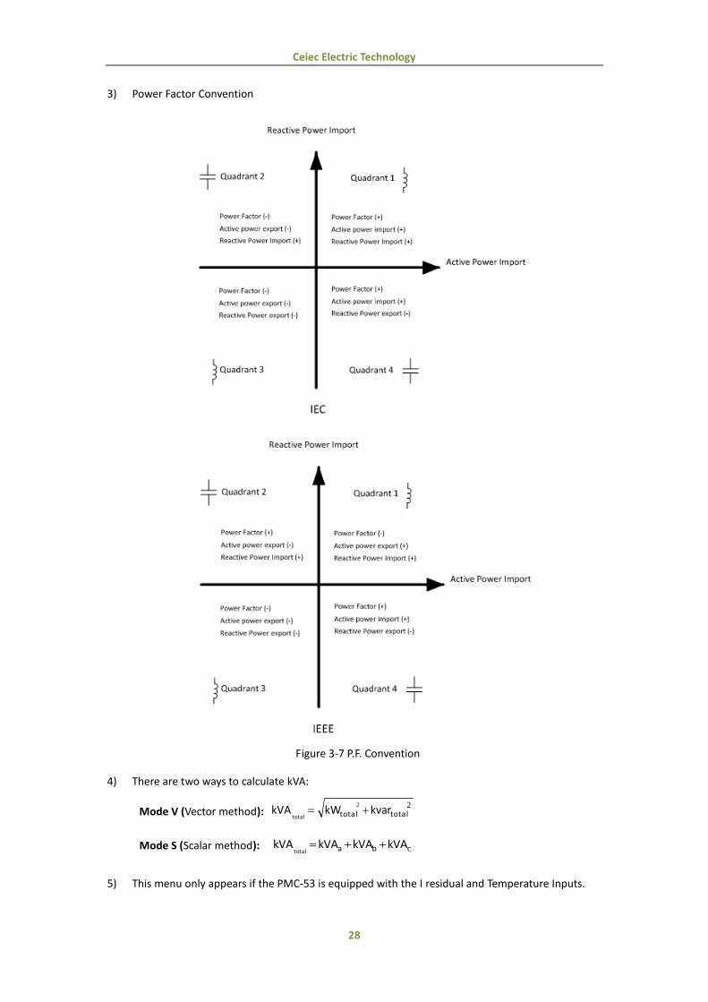
3) Power Factor Convention
Figure 3-7 P.F. Convention
4) There are two ways to calculate kVA:
Mode V (Vector method): 22
totaltotal kvarkWkVAtotal
Mode S (Scalar method): ckVAkVAkVAkVA batotal
5) This menu only appears if the PMC-53 is equipped with the I residual and Temperature Inputs.

Ceiec Electric Technology
29
6) The PMC-53M provides the following pulse constant configurations for different input ratings:
PMC-53M Configurations Pulse Constant Options (imp/kWh, imp/kvarh) Default
57.75VLN/100VLL, 1A 1000/3200/5000/6400/12800 1000
57.75VLN/100VLL, 5A 1000/3200/5000/6400/12800 1000
220VLN/380VLL, 1A 1000/3200/5000/6400/12800 1000
220VLN/380VLL, 5A 1000/3200/5000 1000
Table 3-7 Pulse Constant

Ceiec Electric Technology
30
Chapter 4 Applications
4.1 Inputs and Outputs
4.1.1 Digital Inputs
The PMC-53 optionally provides two self-excited Digital Inputs that are internally wetted at 24 VDC.
Digital Inputs are typically used for monitoring external status which can help prevent equipment
damage, improve maintenance, and track security breaches. The real-time statuses of the Digital
Inputs are available on the front panel LCD Display as well as through communications. Changes in
Digital Input status are stored as events in the SOE Log in 1 ms resolution. Further, the PMC-53
Digital Input provides setpoint capability which can trigger output action when its status changes.
Please refer to Section 4.3.2 for a complete description of the Digital Input Setpoints.
4.1.2 Digital Outputs
The PMC-53 optionally provides two Digital Outputs. They can be of either electromechanical or
solid state type. Digital Outputs are normally used for setpoint alarming, load control, or remote
control applications.
Digital Outputs on the PMC-53 can be used in the following applications:
1) Front Panel Control: Manually operated from the front panel. Please refer to the DO
CTRL setup parameter in Section 3.4.4 for a detailed description.
2) Remote Control: Remotely operated over communications via our free PMC Setup
software or the PecStar® Integrated Energy Management System.
3) Control Setpoint: Control Setpoints can be programmed to trigger DO action upon
becoming active. Please refer to Section 4.3.1 for a detailed
description.
4) Digital Input Setpoint: Digital Inputs can be programmed to trigger DO action upon
becoming active. Please refer to Section 4.3.2 for a detailed
description.
5) I residual Setpoint: If the PMC-53 is equipped with the optional I residual Input, the I
residual ALARM and TRIP setpoints can be enabled to provide
residual current monitoring and trigger DO actions in response to
the I residual setpoints becoming active. Please refer to Section
4.3.3 for a detailed description.
6) Temperature Setpoint: If the PMC-53 is equipped with the optional Temperature input,
the Temperature ALARM setpoint can be enabled to provide
temperature monitoring and trigger DO action in response to the
temperature setpoint becoming active. Please refer to Section
4.3.4 for a detailed description.
Since there are so many ways to utilize the Digital Outputs on the PMC-53, a prioritized scheme
has been developed to avoid conflicts between different applications. In general, Front Panel

Ceiec Electric Technology
31
Control has the highest priority and can override any other applications. Next in the priority list
is Remote Control.
I residual Setpoints, Temperature Setpoint and Digital Input Setpoints share the same priority,
meaning that they can all be programmed to control the same Digital Output. This scheme is
equivalent to having an implicit Logical OR operation for the control of a Digital Output and may
be useful in providing a generic alarm output signal. However, the sharing of a Digital Output is
not recommended if the user intends to generate a control signal in response to a specific
setpoint condition.
Control Setpoints have the lowest priority. It should also be noted that if I residual and/or
Temperature inputs are equipped on the PMC-53, DO1 and DO2 will be reserved for the I residual
and Temperature Setpoints whether they are actually enabled or not. If a Control Setpoint is
programmed to trigger either DO1 or DO2 upon becoming active, the trigger action will not
succeed because Control Setpoints have the lowest priority and therefore will not be able to
control Digital Outputs when I residual and/or Temperature Inputs are present. However,
Control Setpoints can still be used for monitoring and alarming purpose via our PecStar®
Integrated Energy Management System.
4.1.3 Energy Pulse Outputs
The PMC-53 comes standard with two front panel LED Pulse Outputs and can be equipped with two
additional Solid State Digital Outputs for kWh and kvarh pulsing. Energy pulsing can be enabled from
the front panel through the EN PULSE setup parameter. Energy Pulse Outputs are typically used for
accuracy testing. The pulse constant can be configured as 1000/3200/5000/6400/12800 imp/kxh, and
the pulse width is fixed at 80ms. If the PMC-53 is equipped with two Solid State Digital Outputs for
pulsing applications, Terminals DO1 and DO2 are reserved for kWh and kvarh Pulse Outputs,
respectively.
Note:
If the PMC-53M is equipped with the optional I residual and/or Temperature inputs and EN PULSE is
NOT ENABLED, these two front panel LEDs take on different meanings. The green kWh LED shows
the running state by blinking once per second, and the red kvarh LED is lit if there are any active I
residual or Temperature ALARM setpoints.
4.1.4 I residual Input
The PMC-53 optionally provides an I residual Input along with an external Residual Current Sensor
(see Appendix B) that has an input range of 20mA to 1200mA and an output range of 0 to 1.2V. The
outputs of the Residual Current Sensor are connected to the I residual input terminals of the PMC-53
if so equipped. This is illustrated in Figure 4-1 below.
The I residual input provides accurate ground fault monitoring and is mainly used for indirect
grounding protection to ensure personnel safety. Please refer to Section 4.3.3 for a complete
description of the I residual Setpoint operation.

Ceiec Electric Technology
32
Figure 4-1 I Residual Connections
4.1.5 Temperature Input
The PMC-53 optionally provides a RTD Temperature Input along with an external RTD Temperature
Sensor (see Appendix C) to provide temperature measurement. The outputs of the Temperature
Sensor are connected to the Temperature Input of the PMC-53 if so equipped.
The Temperature Input provides accurate temperature monitoring and is mainly used for measuring
the temperature of the Neutral Conductor, Transformer or other equipment that requires temperature
monitoring. Please refer to Section 4.3.4 for a complete description of the Temperature Setpoint
operation.
4.2 Power and Energy
4.2.1 Voltage and Current Phase Angles
Phase analysis is used to identify the angle relationship between the three-phase voltages and
currents.
For Wye connected systems, the per phase difference of the current and voltage angles should
correspond to the per phase PF. For example, if the power factor is 0.5 Lag and the voltage phase
angles are 0.0°, 240.0° and 120.0°, the current phase angles should have the values of -60.0°, 180.0°
and 60.0°.
For Delta connected systems, the current phasors lag line-to-line voltage phasors by 30°. For
example, if the total power factor for a balanced 3-phase system is 0.5 Lag and the line-to-line voltage
phase angles are 0.0°, 240.0° and 120.0°, the current phase angles should have the values of -90.0°,
150.0° and 30.0°.
4.2.2 Energy
Basic energy parameters include active energy (kWh), reactive energy (kvarh) and apparent energy
(kVAh) with a resolution of 0.1k and a maximum value of ±99,999,999.9. When the maximum value
is reached, the energy registers will automatically roll over to zero.
The energy can be reset manually or preset to user-defined values through the front panel or via
communications.
The PMC-53 provides the following energy measurements:

Ceiec Electric Technology
33
Active Energy kWh Import kWh Export
Reactive Energy kvarh Import kvarh Export
Apparent Energy kVAh Total
Table 4-1 Energy
4.2.3 Demands
Demand is defined as the average power consumption over a fixed interval (usually 15 minutes). The
PMC-53 supports the sliding window demand calculation for Ia, Ib, Ic, kW Total, kvar Total and kVA
Total. Demand has the following setup parameters which can be set up via the front panel or over
communications:
# of Sliding Windows: 1-15
Demand Period: 1, 2, 3, 5, 10, 15, 30, 60 minutes. For example, if the # of Sliding
Windows is set as 1 and the Demand Period is 15 minutes, the
demand cycle will be 1×15=15 minutes.
The PMC-53 provides the following Demand parameters. For Peak Demands, both the Peak Demand
value as well as the time stamp are displayed on the front panel. Please refer to Section 3.3 Data
Display for more information.
Real time Demand kW Demand kvar Demand kVA Demand
Ia Demand Ib Demand Ic Demand
Peak Demand kW Peak Demand kvar Demand kVA Demand
Ia Peak Demand Ib Peak Demand Ic Peak Demand
Table 4-2 Demand Parameters
4.3 Setpoints
The PMC-53 provides four different types of setpoints for different applications.
1) Control Setpoint: General purpose control and alarming applications.
2) Digital Input Setpoint: Provides control output actions in response to changes in Digital
Input status.
3) I residual Setpoint: Residual Current monitoring and alarming
4) Temperature Setpoint: Temperature monitoring and alarming
4.3.1 Control Setpoints
The PMC-53 comes standard with 6 user programmable Control Setpoints which provide extensive
control by allowing a user to initiate an action in response to a specific condition. The alarm symbol
at the bottom of the LCD display is lit if there are any active Control Setpoints. Typical setpoint
applications include alarming and fault detection. The setpoints can be programmed over
communications and have the following setup parameters:
1) Setpoint Type: Specifies the parameter to be monitored and the condition of
monitoring (Over or Under). Table 4-3 below provides a list of
Setpoint Parameters and their associated conditions.
Ceiec Electric Technology
34
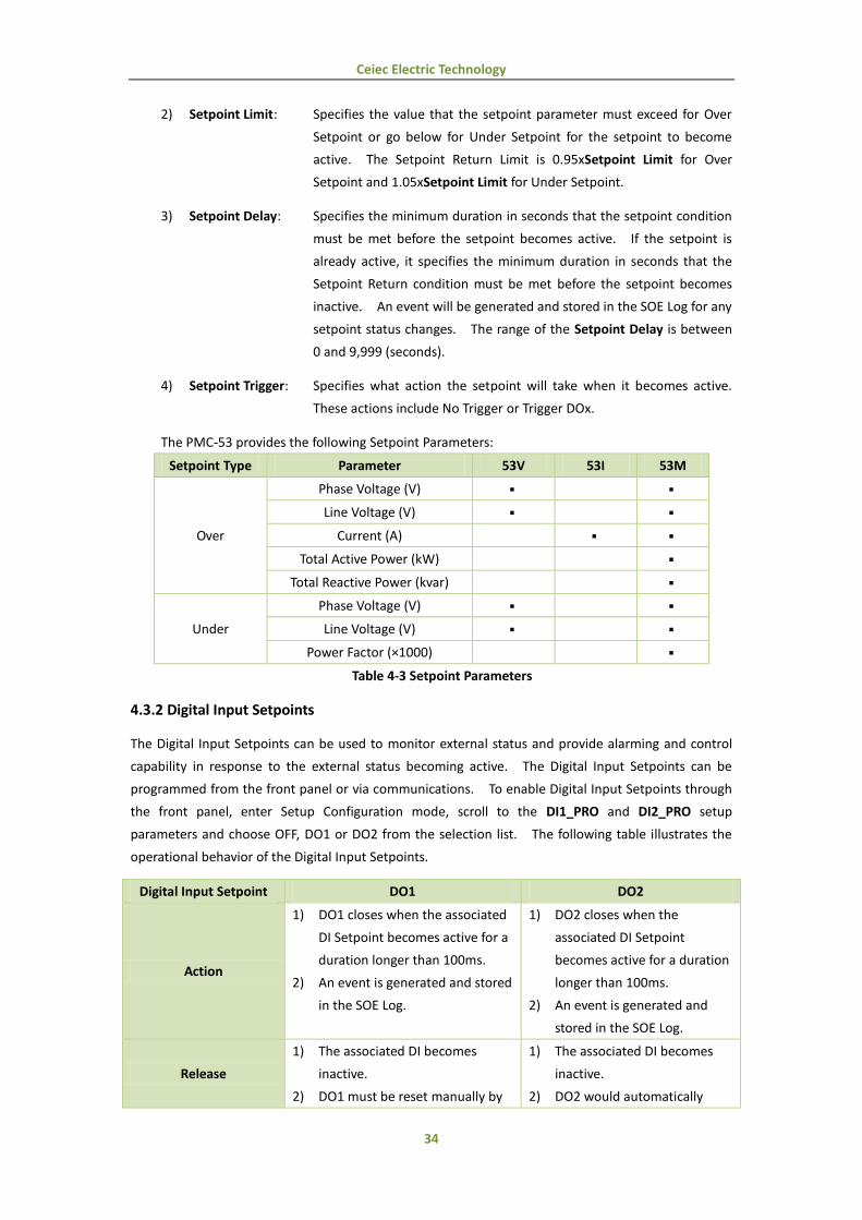
2) Setpoint Limit: Specifies the value that the setpoint parameter must exceed for Over
Setpoint or go below for Under Setpoint for the setpoint to become
active. The Setpoint Return Limit is 0.95xSetpoint Limit for Over
Setpoint and 1.05xSetpoint Limit for Under Setpoint.
3) Setpoint Delay: Specifies the minimum duration in seconds that the setpoint condition
must be met before the setpoint becomes active. If the setpoint is
already active, it specifies the minimum duration in seconds that the
Setpoint Return condition must be met before the setpoint becomes
inactive. An event will be generated and stored in the SOE Log for any
setpoint status changes. The range of the Setpoint Delay is between
0 and 9,999 (seconds).
4) Setpoint Trigger: Specifies what action the setpoint will take when it becomes active.
These actions include No Trigger or Trigger DOx.
The PMC-53 provides the following Setpoint Parameters:
Setpoint Type Parameter 53V 53I 53M
Over
Phase Voltage (V)
Line Voltage (V)
Current (A)
Total Active Power (kW)
Total Reactive Power (kvar)
Under
Phase Voltage (V)
Line Voltage (V)
Power Factor (×1000)
Table 4-3 Setpoint Parameters
4.3.2 Digital Input Setpoints
The Digital Input Setpoints can be used to monitor external status and provide alarming and control
capability in response to the external status becoming active. The Digital Input Setpoints can be
programmed from the front panel or via communications. To enable Digital Input Setpoints through
the front panel, enter Setup Configuration mode, scroll to the DI1_PRO and DI2_PRO setup
parameters and choose OFF, DO1 or DO2 from the selection list. The following table illustrates the
operational behavior of the Digital Input Setpoints.
Digital Input Setpoint DO1 DO2
Action
1) DO1 closes when the associated
DI Setpoint becomes active for a
duration longer than 100ms.
2) An event is generated and stored
in the SOE Log.
1) DO2 closes when the
associated DI Setpoint
becomes active for a duration
longer than 100ms.
2) An event is generated and
stored in the SOE Log.
Release
1) The associated DI becomes
inactive.
2) DO1 must be reset manually by
1) The associated DI becomes
inactive.
2) DO2 would automatically

Ceiec Electric Technology
35
holding down the <System>
button for 3 seconds or via
communications.
open 1 second later.
Table 4-4 Digital Input Setpoint Details
4.3.3 I residual Setpoints
The I residual Setpoints can be used to monitor residual current and provide alarming and control
capability if the residual current exceeds a pre-determined level. The PMC-53 provides two types of I
residual Setpoints: ALARM and TRIP. The programming of the I residual Setpoints is supported
through front panel operation and via communications. These two setpoints can be individually
enabled, and their programming and operational details are illustrated in the following table.
I residual Setpoint ALARM TRIP
Mode ON/OFF ON/OFF
Setpoint Limit 30 to 1000 (mA) 30 to 1000 (mA)
Action/Release Delay 0 to 600 (x0.1S) 0 to 600 (x0.1S)
Setpoint Trigger ON/OFF -
Action
1) I residual >= 0.9 × ALARM
Setpoint Limit
2) The ALARM Setpoint becomes
active when I residual has
exceeded 0.9 x ALARM Setpoint
Limit for a duration longer than
the Action Delay time.
3) When ALARM is active, an SOE
event would be generated, the
front panel Alarm LED would be
lit and the Alarm buzzer would
sound.
4) If Setpoint Trigger is enabled,
DO1 would close.
5) While ALARM is active, the
Alarm buzzer can be muted by
holding down the <Phase>
button for 3 seconds.
1) I residual >= I residual TRIP
Setpoint Limit
2) The TRIP Setpoint becomes
active when I residual has
exceeded the TRIP Setpoint
Limit for a duration longer
than the Action Delay time.
3) When TRIP is active, an SOE
event would be generated
and DO2 would close.
Release
1) I residual < 0.8 × ALARM
Setpoint Limit
2) The ALARM Setpoint becomes
inactive when I residual is less
than 0.8 x ALARM Setpoint Limit
for a duration longer than the
Release Delay time.
3) The front panel Alarm LED, the
Alarm buzzer, and DO1 (if
1) I residual < 0.8 × TRIP
Setpoint Limit
2) The TRIP Setpoint becomes
inactive when I residual is less
than 0.8 x TRIP Setpoint Limit
for a duration longer than the
Release Delay time.
3) DO2 would open
automatically.
Ceiec Electric Technology
36
enabled) must be reset manually
by holding down the <System>
button for 3 seconds or via
communications after the I
residual ALARM has become
inactive.
Table 4-5 I Residual ALARM and TRIP Setpoints
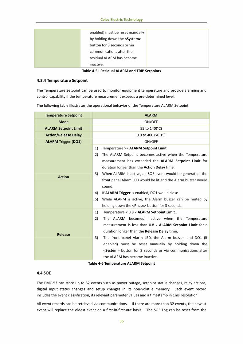
4.3.4 Temperature Setpoint
The Temperature Setpoint can be used to monitor equipment temperature and provide alarming and
control capability if the temperature measurement exceeds a pre-determined level.
The following table illustrates the operational behavior of the Temperature ALARM Setpoint.
Temperature Setpoint ALARM
Mode ON/OFF
ALARM Setpoint Limit 55 to 140(°C)
Action/Release Delay 0.0 to 400 (x0.1S)
ALARM Trigger (DO1) ON/OFF
Action
1) Temperature >= ALARM Setpoint Limit
2) The ALARM Setpoint becomes active when the Temperature
measurement has exceeded the ALARM Setpoint Limit for
duration longer than the Action Delay time.
3) When ALARM is active, an SOE event would be generated, the
front panel Alarm LED would be lit and the Alarm buzzer would
sound.
4) If ALARM Trigger is enabled, DO1 would close.
5) While ALARM is active, the Alarm buzzer can be muted by
holding down the <Phase> button for 3 seconds.
Release
1) Temperature < 0.8 × ALARM Setpoint Limit.
2) The ALARM becomes inactive when the Temperature
measurement is less than 0.8 x ALARM Setpoint Limit for a
duration longer than the Release Delay time.
3) The front panel Alarm LED, the Alarm buzzer, and DO1 (if
enabled) must be reset manually by holding down the
<System> button for 3 seconds or via communications after
the ALARM has become inactive.
Table 4-6 Temperature ALARM Setpoint
4.4 SOE
The PMC-53 can store up to 32 events such as power outage, setpoint status changes, relay actions,
digital input status changes and setup changes in its non-volatile memory. Each event record
includes the event classification, its relevant parameter values and a timestamp in 1ms resolution.
All event records can be retrieved via communications. If there are more than 32 events, the newest
event will replace the oldest event on a first-in-first-out basis. The SOE Log can be reset from the

Ceiec Electric Technology
37
front panel or via communications.
4.5 Power Quality
4.5.1 Harmonics
The PMC-53 provides harmonic analysis for THD. All harmonic parameters are available through
communications as well as the front panel LCD display.
The PMC-53 provides the following Harmonic measurements:
Harmonics
Va THD Vb THD Vc THD
Ia THD Ib THD Ic THD
Ia K-Factor Ib K-Factor Ic K-Factor
Table 4-7 Harmonic Measurements
4.5.2 Unbalance
The PMC-53 can measure Voltage and Current Unbalances. The calculation method of Voltage and
Current Unbalances is listed below:
100%Vavg
|]VavgVc||,VavgVb||,VavgVa[|UnblanceVoltage MAX
100%Iavg
|]IavgIc||,VavgIb||,IavgIa[| UnblanceCurrent MAX

Ceiec Electric Technology
38
Chapter 5 Modbus Register Map
This chapter provides a complete description of the Modbus register map (Protocol Version 6.0) for
the PMC-53 series power meter to facilitate the development of 3rd
party communications driver for
accessing information on the PMC-53. In general, the registers on the PMC-53 are implemented as
Modbus Holding Registers (4XXXXX) with the exception of the DO Control registers, which are
implemented as “Write Only” Modbus Coil Registers (0XXXXX). The PMC-53 supports 6-digit
addressing scheme and the following Modbus functions:
1) Read Holding Registers (Function Code 0x03)
2) Force Single Coil (Function Code 0x05)
3) Preset Multiple Registers (Function Code 0x10)
The register addresses are listed without the Modbus Address Prefix, 4 for Holding Registers and 0
for Coil Registers. Therefore, it’s not necessary to subtract 400001 for Holding Registers or 000001
for Coil Registers to obtain the starting address number. For a complete Modbus Protocol
Specification, please visit http://www.modbus.org.
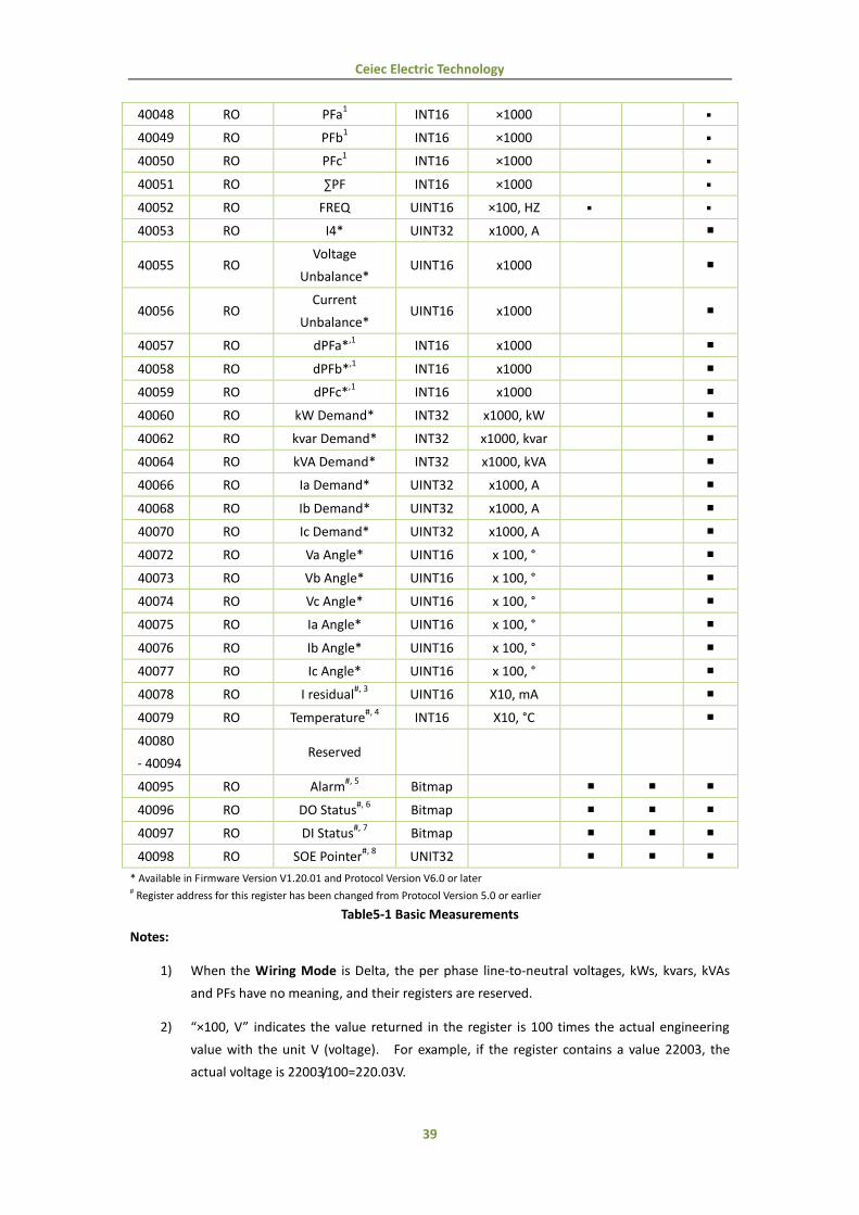
5.1 Basic Measurements
Register Property Description Format Scale/Unit PMC-53 Model
V I M
40000 RO Va1 UINT32 ×100, V
2
40002 RO Vb1 UINT32 ×100, V
40004 RO Vc1 UINT32 ×100, V
40006 RO VLN average UINT32 ×100, V
40008 RO Vab UINT32 ×100, V
40010 RO Vbc UINT32 ×100, V
40012 RO Vca UINT32 ×100, V
40014 RO VLL average UINT32 ×100, V
40016 RO Ia UINT32 ×1000, A
40018 RO Ib UINT32 ×1000, A
40020 RO Ic UINT32 ×1000, A
40022 RO I average UINT32 ×1000, A
40024 RO kWa1 INT32 ×1000, kW
40026 RO kWb1 INT32 ×1000, kW
40028 RO kWc1 INT32 ×1000, kW
40030 RO ∑kW INT32 ×1000, kW
40032 RO kvara1 INT32 ×1000, kvar
40034 RO kvarb1 INT32 ×1000, kvar
40036 RO kvarc1 INT32 ×1000, kvar
40038 RO ∑kvar INT32 ×1000, kvar
40040 RO kVAa1 INT32 ×1000, kVA
40042 RO kVAb1 INT32 ×1000, kVA
40044 RO kVAc1 INT32 ×1000, kVA
40046 RO ∑kVA INT32 ×1000, kVA
Ceiec Electric Technology
39
40048 RO PFa1 INT16 ×1000
40049 RO PFb1 INT16 ×1000
40050 RO PFc1 INT16 ×1000
40051 RO ∑PF INT16 ×1000
40052 RO FREQ UINT16 ×100, HZ
40053 RO I4* UINT32 x1000, A
40055 RO Voltage
Unbalance* UINT16 x1000
40056 RO Current
Unbalance* UINT16 x1000
40057 RO dPFa*,1
INT16 x1000
40058 RO dPFb*,1
INT16 x1000
40059 RO dPFc*,1
INT16 x1000
40060 RO kW Demand* INT32 x1000, kW
40062 RO kvar Demand* INT32 x1000, kvar
40064 RO kVA Demand* INT32 x1000, kVA
40066 RO Ia Demand* UINT32 x1000, A
40068 RO Ib Demand* UINT32 x1000, A
40070 RO Ic Demand* UINT32 x1000, A
40072 RO Va Angle* UINT16 x 100, °
40073 RO Vb Angle* UINT16 x 100, °
40074 RO Vc Angle* UINT16 x 100, °
40075 RO Ia Angle* UINT16 x 100, °
40076 RO Ib Angle* UINT16 x 100, °
40077 RO Ic Angle* UINT16 x 100, °
40078 RO I residual#, 3
UINT16 X10, mA
40079 RO Temperature#, 4
INT16 X10, °C
40080
- 40094 Reserved
40095 RO Alarm#, 5
Bitmap
40096 RO DO Status#, 6
Bitmap
40097 RO DI Status#, 7
Bitmap
40098 RO SOE Pointer#, 8
UNIT32
* Available in Firmware Version V1.20.01 and Protocol Version V6.0 or later # Register address for this register has been changed from Protocol Version 5.0 or earlier
Table5-1 Basic Measurements
Notes:
1) When the Wiring Mode is Delta, the per phase line-to-neutral voltages, kWs, kvars, kVAs
and PFs have no meaning, and their registers are reserved.
2) “×100, V” indicates the value returned in the register is 100 times the actual engineering
value with the unit V (voltage). For example, if the register contains a value 22003, the
actual voltage is 22003/100=220.03V.

Ceiec Electric Technology
40
3) When the residual current sensor is not connected, the value in register 40078 is 0x7FFF.
4) When the temperature sensor was broken or not connected, the value in register 40079 is
30000. When the temperature is below -40°C, the value in register 40079 is -400.
5) The Alarm register indicates the various alarm states with a bit value of 1 meaning active
and 0 meaning inactive. The following table illustrates the details of the Alarm register.
For PMC-53I and PMC-53V, B0 to B2 are reserved.
Bit Alarm Event
B0 I residual ALARM
B1 I residual TRIP
B2 Temperature ALARM
B3 Setpoint 1
B4 Setpoint 2
B5 Setpoint 3
B6 Setpoint 4
B7 Setpoint 5
B8 Setpoint 6
Other bits Reserved
Table 5-2 Alarm Register (40095)
6) For the DO Status register, the bit values of B0 and B1 represent the states of DO1 and DO2,
respectively, with “1” meaning active (closed) and “0” meaning inactive (open).
7) For the DI Status register, the bit values of B0 and B1 represent the states of DI1 and DI2,
respectively, with “1” meaning active (closed) and “0” meaning inactive (open).
8) The range of the SOE Pointer is between 0 and 0xFFFFFFFF. The SOE Pointer is incremented
by one for every event generated, and will roll over to 0 if its current value is 0xFFFFFFFF.
Since the SOE Pointer is a 32-bit value and the SOE Log capacity is relatively small with only
32 events in the PMC-53, an assumption has been made that the SOE Pointer will never roll
over. If a CLR SOE is performed from the front panel or via communications, the SOE
Pointer will be reset to zero and then immediately incremented by one with a new ”Setup
Changes via Front Panel” or “Setup Changes via Communications” event. Therefore, any
3rd
party software should assume that a CLR SOE action has been performed if it sees the
SOE Pointer rolling over to one or to a value that is smaller than its own pointer. In this
case, the new SOE Pointer also indicates the number of events in the SOE Log if it is less
than 32. Otherwise, there will always be 32 events in the SOE Log.
5.2 Energy Measurements
Register Property Description Format unit PMC-53 Model
V I M
40100 RW kWh Import UINT32 x0.1kWh
40102 RW kWh Export UINT32 X0.1kWh
40104 Reserved
40106 RW kvarh Import UINT32 X0.1kvarh
Ceiec Electric Technology
41
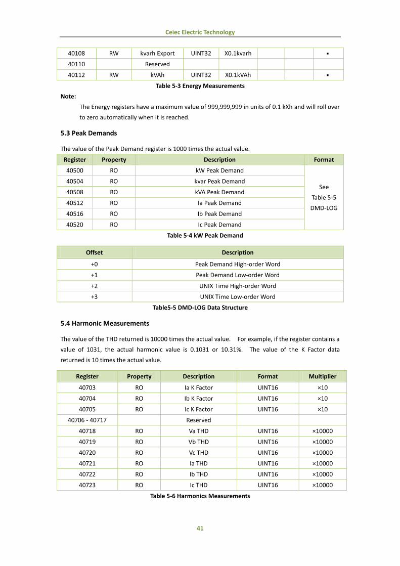
40108 RW kvarh Export UINT32 X0.1kvarh
40110 Reserved
40112 RW kVAh UINT32 X0.1kVAh
Table 5-3 Energy Measurements
Note:
The Energy registers have a maximum value of 999,999,999 in units of 0.1 kXh and will roll over
to zero automatically when it is reached.
5.3 Peak Demands
The value of the Peak Demand register is 1000 times the actual value.
Register Property Description Format
40500 RO kW Peak Demand
See
Table 5-5
DMD-LOG
40504 RO kvar Peak Demand
40508 RO kVA Peak Demand
40512 RO Ia Peak Demand
40516 RO Ib Peak Demand
40520 RO Ic Peak Demand
Table 5-4 kW Peak Demand
Offset Description
+0 Peak Demand High-order Word
+1 Peak Demand Low-order Word
+2 UNIX Time High-order Word
+3 UNIX Time Low-order Word
Table5-5 DMD-LOG Data Structure
5.4 Harmonic Measurements
The value of the THD returned is 10000 times the actual value. For example, if the register contains a
value of 1031, the actual harmonic value is 0.1031 or 10.31%. The value of the K Factor data
returned is 10 times the actual value.
Register Property Description Format Multiplier
40703 RO Ia K Factor UINT16 ×10
40704 RO Ib K Factor UINT16 ×10
40705 RO Ic K Factor UINT16 ×10
40706 - 40717 Reserved
40718 RO Va THD UINT16 ×10000
40719 RO Vb THD UINT16 ×10000
40720 RO Vc THD UINT16 ×10000
40721 RO Ia THD UINT16 ×10000
40722 RO Ib THD UINT16 ×10000
40723 RO Ic THD UINT16 ×10000
Table 5-6 Harmonics Measurements
Ceiec Electric Technology
42
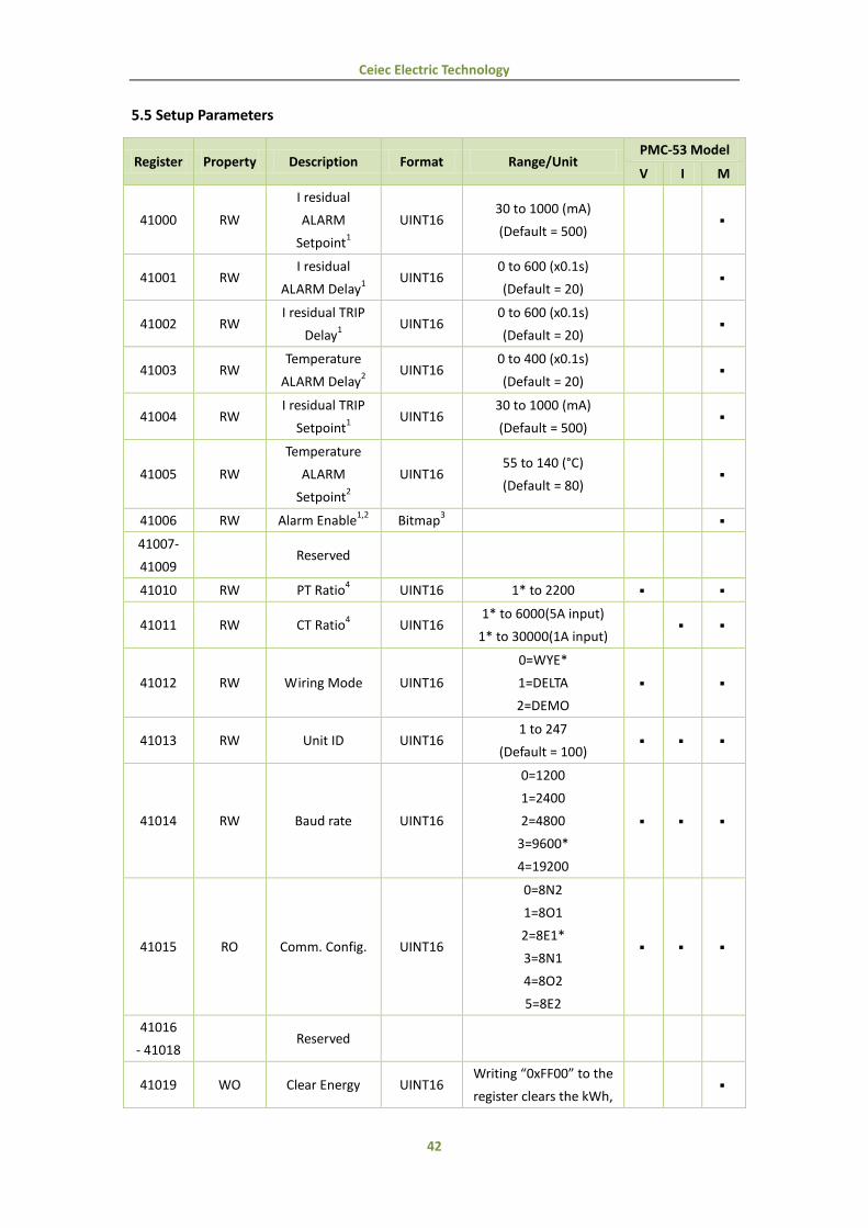
5.5 Setup Parameters
Register Property Description Format Range/Unit PMC-53 Model
V I M
41000 RW
I residual
ALARM
Setpoint1
UINT16 30 to 1000 (mA)
(Default = 500)
41001 RW I residual
ALARM Delay1
UINT16 0 to 600 (x0.1s)
(Default = 20)
41002 RW I residual TRIP
Delay1
UINT16 0 to 600 (x0.1s)
(Default = 20)
41003 RW Temperature
ALARM Delay2
UINT16 0 to 400 (x0.1s)
(Default = 20)
41004 RW I residual TRIP
Setpoint1
UINT16 30 to 1000 (mA)
(Default = 500)
41005 RW
Temperature
ALARM
Setpoint2
UINT16 55 to 140 (°C)
(Default = 80)
41006 RW Alarm Enable1,2
Bitmap3
41007-
41009 Reserved
41010 RW PT Ratio4 UINT16 1* to 2200
41011 RW CT Ratio4 UINT16
1* to 6000(5A input)
1* to 30000(1A input)
41012 RW Wiring Mode UINT16
0=WYE*
1=DELTA
2=DEMO
41013 RW Unit ID UINT16 1 to 247
(Default = 100)
41014 RW Baud rate UINT16
0=1200
1=2400
2=4800
3=9600*
4=19200
41015 RO Comm. Config. UINT16
0=8N2
1=8O1
2=8E1*
3=8N1
4=8O2
5=8E2
41016
- 41018 Reserved
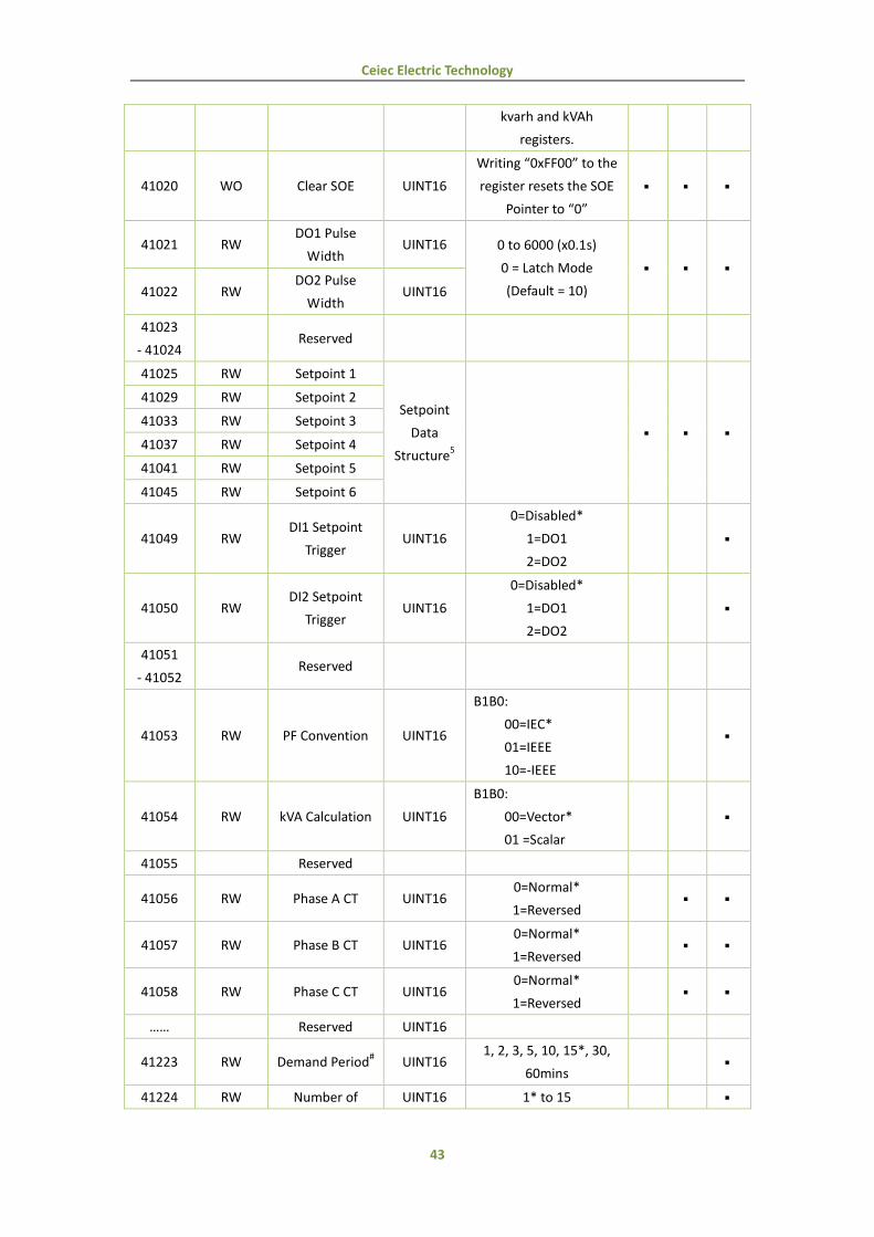
41019 WO Clear Energy UINT16 Writing “0xFF00” to the
register clears the kWh,
Ceiec Electric Technology
43
kvarh and kVAh
registers.
41020 WO Clear SOE UINT16
Writing “0xFF00” to the
register resets the SOE
Pointer to “0”
41021 RW DO1 Pulse
Width UINT16 0 to 6000 (x0.1s)
0 = Latch Mode
(Default = 10)
41022 RW DO2 Pulse
Width UINT16
41023
- 41024 Reserved
41025 RW Setpoint 1
Setpoint
Data
Structure5
41029 RW Setpoint 2
41033 RW Setpoint 3
41037 RW Setpoint 4
41041 RW Setpoint 5
41045 RW Setpoint 6
41049 RW DI1 Setpoint
Trigger UINT16
0=Disabled*
1=DO1
2=DO2
41050 RW DI2 Setpoint
Trigger UINT16
0=Disabled*
1=DO1
2=DO2
41051
- 41052 Reserved
41053 RW PF Convention UINT16
B1B0:
00=IEC*
01=IEEE
10=-IEEE
41054 RW kVA Calculation UINT16
B1B0:
00=Vector*
01 =Scalar
41055 Reserved
41056 RW Phase A CT UINT16 0=Normal*
1=Reversed
41057 RW Phase B CT UINT16 0=Normal*
1=Reversed
41058 RW Phase C CT UINT16 0=Normal*
1=Reversed
…… Reserved UINT16
41223 RW Demand Period# UINT16
1, 2, 3, 5, 10, 15*, 30,
60mins
41224 RW Number of UINT16 1* to 15

Ceiec Electric Technology
44
Sliding
Windows#
41225 Reserved
41226 WO Clear Peak
Demands#
UINT16
Writing ”0xFF00” to the
register resets the Peak
Demand to “0”
# Available in Firmware Version V1.20.01 and Protocol Version V6.0 or later
*Default
Table5-7 Setup Parameters
Notes:
1) Registers 41000-41002, 41004 and 41006 are valid only if the meter is equipped with the I
residual Input. Otherwise, they are reserved.
2) Registers 41003, 41005 and 41006 are valid only if the meter is equipped with the
Temperature Input. Otherwise, they are reserved.
3) The bitmap definition of the Alarm Enable register is shown in the following table. For Bits
0 to 4, the value “1” means that the specified function is enabled; otherwise, it is disabled.
Bits 5 to 15 are reserved.
Bit 4 3 2 1 0
Function
Temperature
ALARM DO1
Trigger
I residual
ALARM DO1
Trigger
Temperature
ALARM Enable
I residual
TRIP Enable
I residual
ALARM Enable
Table 5-8 Alarm Enable Register Bitmap Definition (41006)
4) PT Ratio × CT Ratio × Rated Phase Voltage Input × Rated Current Input x √3 must be less
than 790,000,000.
5) Setpoint Data Structure
Offset Format Description
+0
(low-order) UINT16
Over Setpoint Under Setpoint
1=VLN, 2=VLL, 3=I, 4=∑P, 5=∑Q 6=VLN, 7=VLL, 8=∑PF
+0
(high-order) Setpoint Trigger: 0= No Trigger, 1=Trigger DO1, 2=Trigger DO2
+1 UINT32 Setpoint Limit
+3 UINT16 Setpoint Delay: 0 to 9999 (seconds)
Table 5-9 Setpoint Data Structure
The Setpoint Limit for PF is 1000 times the actual PF value. For example, if the actual desired limit is
0.866, the Setpoint Limit should be specified as 866.
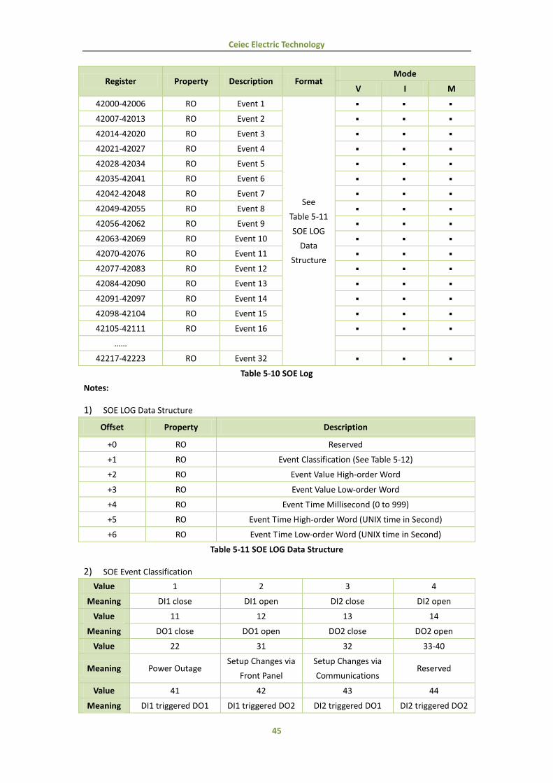
5.6 SOE Log
Each SOE event occupies 7 registers as shown in the following table. The SOE LOG Data Structure is
described in Table 5-11.
Ceiec Electric Technology
45
Register Property Description Format Mode
V I M
42000-42006 RO Event 1
See
Table 5-11
SOE LOG
Data
Structure
42007-42013 RO Event 2
42014-42020 RO Event 3
42021-42027 RO Event 4
42028-42034 RO Event 5
42035-42041 RO Event 6
42042-42048 RO Event 7
42049-42055 RO Event 8
42056-42062 RO Event 9
42063-42069 RO Event 10
42070-42076 RO Event 11
42077-42083 RO Event 12
42084-42090 RO Event 13
42091-42097 RO Event 14
42098-42104 RO Event 15
42105-42111 RO Event 16
……
42217-42223 RO Event 32
Table 5-10 SOE Log
Notes:
1) SOE LOG Data Structure
Offset Property Description
+0 RO Reserved
+1 RO Event Classification (See Table 5-12)
+2 RO Event Value High-order Word
+3 RO Event Value Low-order Word
+4 RO Event Time Millisecond (0 to 999)
+5 RO Event Time High-order Word (UNIX time in Second)
+6 RO Event Time Low-order Word (UNIX time in Second)
Table 5-11 SOE LOG Data Structure
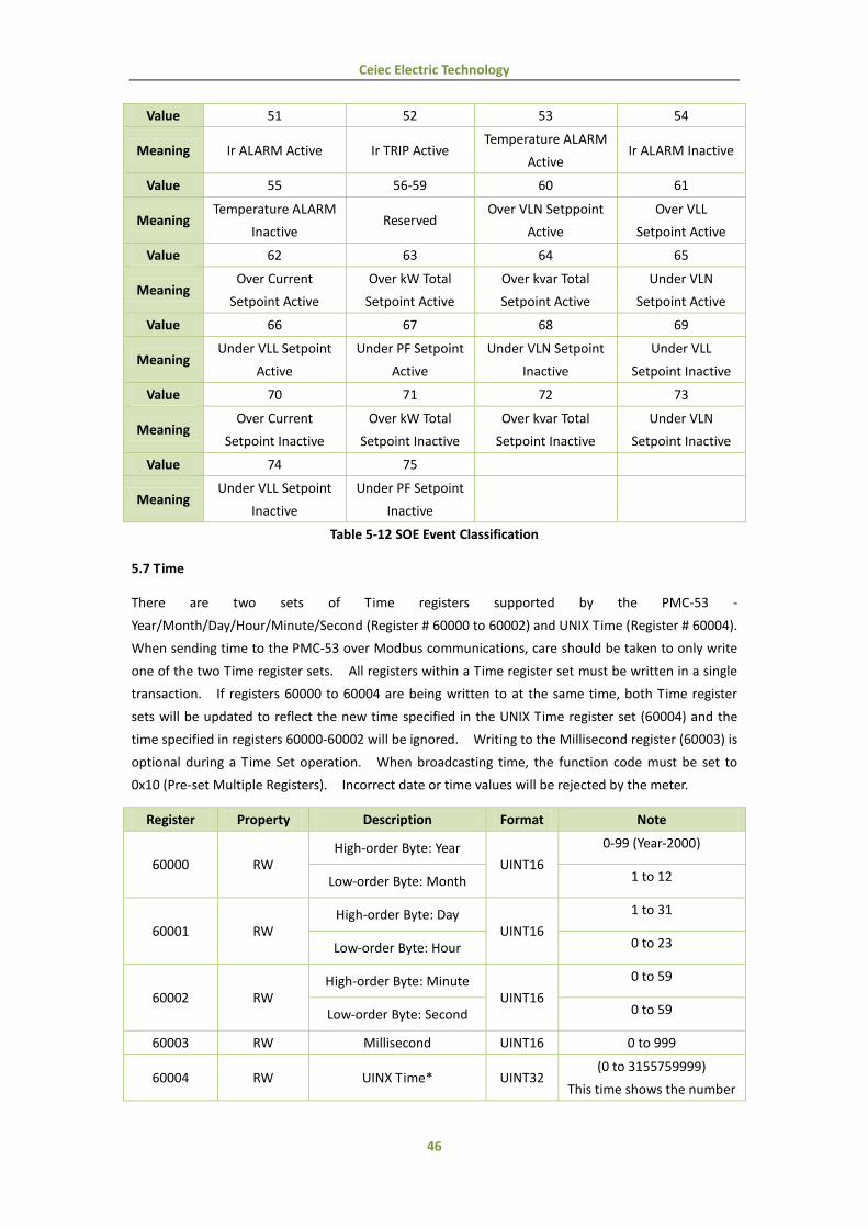
2) SOE Event Classification
Value 1 2 3 4
Meaning DI1 close DI1 open DI2 close DI2 open
Value 11 12 13 14
Meaning DO1 close DO1 open DO2 close DO2 open
Value 22 31 32 33-40
Meaning Power Outage Setup Changes via
Front Panel
Setup Changes via
Communications Reserved
Value 41 42 43 44
Meaning DI1 triggered DO1 DI1 triggered DO2 DI2 triggered DO1 DI2 triggered DO2
Ceiec Electric Technology
46
Value 51 52 53 54
Meaning Ir ALARM Active Ir TRIP Active Temperature ALARM
Active Ir ALARM Inactive
Value 55 56-59 60 61
Meaning Temperature ALARM
Inactive Reserved
Over VLN Setppoint
Active
Over VLL
Setpoint Active
Value 62 63 64 65
Meaning Over Current
Setpoint Active
Over kW Total
Setpoint Active
Over kvar Total
Setpoint Active
Under VLN
Setpoint Active
Value 66 67 68 69
Meaning Under VLL Setpoint
Active
Under PF Setpoint
Active
Under VLN Setpoint
Inactive
Under VLL
Setpoint Inactive
Value 70 71 72 73
Meaning Over Current
Setpoint Inactive
Over kW Total
Setpoint Inactive
Over kvar Total
Setpoint Inactive
Under VLN
Setpoint Inactive
Value 74 75
Meaning Under VLL Setpoint
Inactive
Under PF Setpoint
Inactive
Table 5-12 SOE Event Classification
5.7 Time
There are two sets of Time registers supported by the PMC-53 -
Year/Month/Day/Hour/Minute/Second (Register # 60000 to 60002) and UNIX Time (Register # 60004).
When sending time to the PMC-53 over Modbus communications, care should be taken to only write
one of the two Time register sets. All registers within a Time register set must be written in a single
transaction. If registers 60000 to 60004 are being written to at the same time, both Time register
sets will be updated to reflect the new time specified in the UNIX Time register set (60004) and the
time specified in registers 60000-60002 will be ignored. Writing to the Millisecond register (60003) is
optional during a Time Set operation. When broadcasting time, the function code must be set to
0x10 (Pre-set Multiple Registers). Incorrect date or time values will be rejected by the meter.
Register Property Description Format Note
60000 RW High-order Byte: Year
UINT16
0-99 (Year-2000)
Low-order Byte: Month 1 to 12
60001 RW High-order Byte: Day
UINT16
1 to 31
Low-order Byte: Hour 0 to 23
60002 RW High-order Byte: Minute
UINT16
0 to 59
Low-order Byte: Second 0 to 59
60003 RW Millisecond UINT16 0 to 999
60004 RW UINX Time* UINT32 (0 to 3155759999)
This time shows the number

Ceiec Electric Technology
47
of seconds since 00:00:00
January 1, 1970
* Available in Firmware Version V1.20.01 and Protocol Version V6.0 or later
Table 5-13 Time Registers
5.8 DO Control
The DO Control registers are implemented as “Write-Only” Modbus Coil Registers (0XXXXX) and can
be controlled with the Force Single Coil command (Function Code 0x05). The PMC-53 does not
support the Read Coils command (Function Code 0x01) because DO Control registers are “Write-Only”.
Register 40066 (DO Status) should be read instead to determine the current DO status.
The PMC-53 adopts the ARM before EXECUTE operation for the remote control of its Digital Outputs.
Before executing an OPEN or CLOSE command on a Digital Output, it must be “Armed” first. This is
achieved by writing the value 0xFF00 to the appropriate register to “Arm” a particular DO operation.
The DO will be “Disarmed” if an “Execute” command is not received within 15 seconds after it has
been “Armed”. If an “Execute” command is received without first having received an “Arm”
command, the meter ignores the “Execute” command and returns the 0x04 exception code.
Register Property Format Description
60064 WO UINT16 Arm DO1 close
60065 WO UINT16 Execute DO1 close
60066 WO UINT16 Arm DO1 open
60067 WO UINT16 Execute DO1 open
60068 WO UINT16 Arm DO2 close
60069 WO UINT16 Execute DO2 close
60070 WO UINT16 Arm DO2 open
60071 WO UINT16 Execute DO2 open
60072-60127 Reserved
60128 WO UINT16 Arm the reset of Alarm LED and Buzzer
60129 WO UINT16 Execute the reset of Alarm LED and Buzzer
Table 5-14 DO Control Registers
5.9 Meter Information
Register Property Description Format Note
60200- 60219 RO Meter model1 UINT16 See Table 5-16
60220 RO Firmware Version UINT16 e.g. 10000 means V1.00.00
60221 RO Protocol Version UINT16 e.g. 40 means V4.0
60222 RO Firmware Update Date:
Year-2000 UINT16
e.g. 080709 means July 9,
2008 60223 RO
Firmware Update Date:
Month UINT16
60224 RO Firmware Update Date:
Day UINT16
60225 RO Serial Number: UINT32 e.g. 0908471895 means that
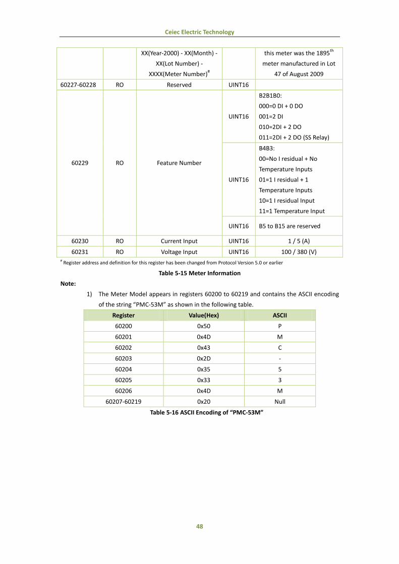
Ceiec Electric Technology
48
XX(Year-2000) - XX(Month) -
XX(Lot Number) -
XXXX(Meter Number)#
this meter was the 1895th
meter manufactured in Lot
47 of August 2009
60227-60228 RO Reserved UINT16
60229 RO Feature Number
UINT16
B2B1B0:
000=0 DI + 0 DO
001=2 DI
010=2DI + 2 DO
011=2DI + 2 DO (SS Relay)
UINT16
B4B3:
00=No I residual + No
Temperature Inputs
01=1 I residual + 1
Temperature Inputs
10=1 I residual Input
11=1 Temperature Input
UINT16 B5 to B15 are reserved
60230 RO Current Input UINT16 1 / 5 (A)
60231 RO Voltage Input UINT16 100 / 380 (V) # Register address and definition for this register has been changed from Protocol Version 5.0 or earlier
Table 5-15 Meter Information
Note:
1) The Meter Model appears in registers 60200 to 60219 and contains the ASCII encoding
of the string “PMC-53M” as shown in the following table.
Register Value(Hex) ASCII
60200 0x50 P
60201 0x4D M
60202 0x43 C
60203 0x2D -
60204 0x35 5
60205 0x33 3
60206 0x4D M
60207-60219 0x20 Null
Table 5-16 ASCII Encoding of “PMC-53M”

Ceiec Electric Technology
49
Revision History
Revision Date Description
4.0A 20100623 First Edition
5.0A 20110225
P2: Added the explanation for the graphic symbols for Danger
and Caution
P7: Updated the description for Figures descriptions
P9: Updated the Models and Measurements Table
P18: Added Section 3.1.2 LCD Display Areas
P20: Added Section 3.1.3 Peak Demand Display
Added Section 3.2 LED Indicators
P22: Updated Table 3-5 Data display screens of PMC-53M
P24: Updated Figure 3-4 Setup Menu
P25: Updated Table 3-6 Setup Parameters
P31: Added Section 4.2 Power and Energy
P36: Added Section 4.5 Power Quality
P37: Updated Table5-1 Basic Measurements
P40: Added Section 5.3 Peak Demands
P40: Added Section 5.4 Harmonics Measurements
P41: Updated Table5-7 Setup Parameters
P46: Added the description for UNIX Time registers
P48: Added “Revision History”
P49: Updated the Power Supply specification in Appendix A
Updated the Voltage Input specification in Appendix A
P51: Added the Pollution Degree and Measurement Category
to the Technical Specifications in Appendix A
P51: Updated the Residual Current Sensor Ordering Guide in
Appendix B
P54: Updated the Standards Compliance Table in Appendix C
P55: Updated the PMC-53 Ordering Guide in Appendix E
V5.2A 20120207
P9: Updated the application figure
P11: Updated the Figure 2-1 Appearance
P14: Added the Figure 2-6 3-wire Delta, Direct Connection
P16: Updated Figure 2-10 RS485 Communication Connections
P18: Update Figure 3-1 Front Panel
P24: Updated the Figure 3-6 Setup Menu
P27: Added the Pulse Constant in Table 3-5 Setup Parameters
P56: Updated the PMC-53 Ordering Guide in Appendix E
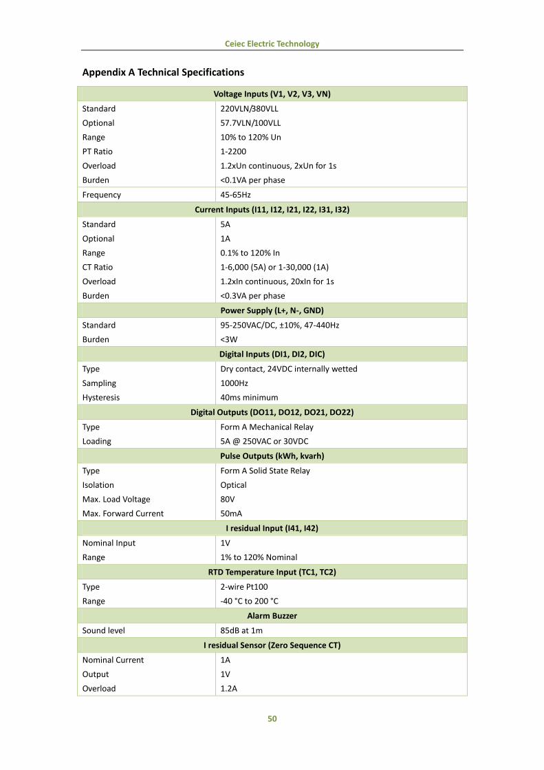
Ceiec Electric Technology
50
Appendix A Technical Specifications
Voltage Inputs (V1, V2, V3, VN)
Standard
Optional
Range
PT Ratio
Overload
Burden
220VLN/380VLL
57.7VLN/100VLL
10% to 120% Un
1-2200
1.2xUn continuous, 2xUn for 1s
<0.1VA per phase
Frequency 45-65Hz
Current Inputs (I11, I12, I21, I22, I31, I32)
Standard
Optional
Range
CT Ratio
Overload
Burden
5A
1A
0.1% to 120% In
1-6,000 (5A) or 1-30,000 (1A)
1.2xIn continuous, 20xIn for 1s
<0.3VA per phase
Power Supply (L+, N-, GND)
Standard
Burden
95-250VAC/DC, ±10%, 47-440Hz
<3W
Digital Inputs (DI1, DI2, DIC)
Type
Sampling
Hysteresis
Dry contact, 24VDC internally wetted
1000Hz
40ms minimum
Digital Outputs (DO11, DO12, DO21, DO22)
Type
Loading
Form A Mechanical Relay
5A @ 250VAC or 30VDC
Pulse Outputs (kWh, kvarh)
Type
Isolation
Max. Load Voltage
Max. Forward Current
Form A Solid State Relay
Optical
80V
50mA
I residual Input (I41, I42)
Nominal Input
Range
1V
1% to 120% Nominal
RTD Temperature Input (TC1, TC2)
Type
Range
2-wire Pt100
-40 °C to 200 °C
Alarm Buzzer
Sound level 85dB at 1m
I residual Sensor (Zero Sequence CT)
Nominal Current
Output
Overload
1A
1V
1.2A
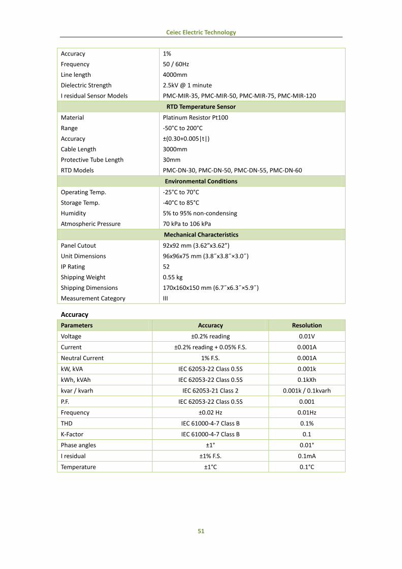
Ceiec Electric Technology
51
Accuracy
Frequency
Line length
Dielectric Strength
I residual Sensor Models
1%
50 / 60Hz
4000mm
2.5kV @ 1 minute
PMC-MIR-35, PMC-MIR-50, PMC-MIR-75, PMC-MIR-120
RTD Temperature Sensor
Material
Range
Accuracy
Cable Length
Protective Tube Length
RTD Models
Platinum Resistor Pt100
-50°C to 200°C
±(0.30+0.005|t|)
3000mm
30mm
PMC-DN-30, PMC-DN-50, PMC-DN-55, PMC-DN-60
Environmental Conditions
Operating Temp.
Storage Temp.
Humidity
Atmospheric Pressure
-25°C to 70°C
-40°C to 85°C
5% to 95% non-condensing
70 kPa to 106 kPa
Mechanical Characteristics
Panel Cutout
Unit Dimensions
IP Rating
Shipping Weight
Shipping Dimensions
Measurement Category
92x92 mm (3.62”x3.62”)
96x96x75 mm (3.8˝x3.8˝×3.0˝)
52
0.55 kg
170x160x150 mm (6.7˝x6.3˝×5.9˝)
III
Accuracy
Parameters Accuracy Resolution
Voltage ±0.2% reading 0.01V
Current ±0.2% reading + 0.05% F.S. 0.001A
Neutral Current 1% F.S. 0.001A
kW, kVA IEC 62053-22 Class 0.5S 0.001k
kWh, kVAh IEC 62053-22 Class 0.5S 0.1kXh
kvar / kvarh IEC 62053-21 Class 2 0.001k / 0.1kvarh
P.F. IEC 62053-22 Class 0.5S 0.001
Frequency ±0.02 Hz 0.01Hz
THD IEC 61000-4-7 Class B 0.1%
K-Factor IEC 61000-4-7 Class B 0.1
Phase angles ±1° 0.01°
I residual ±1% F.S. 0.1mA
Temperature ±1°C 0.1°C
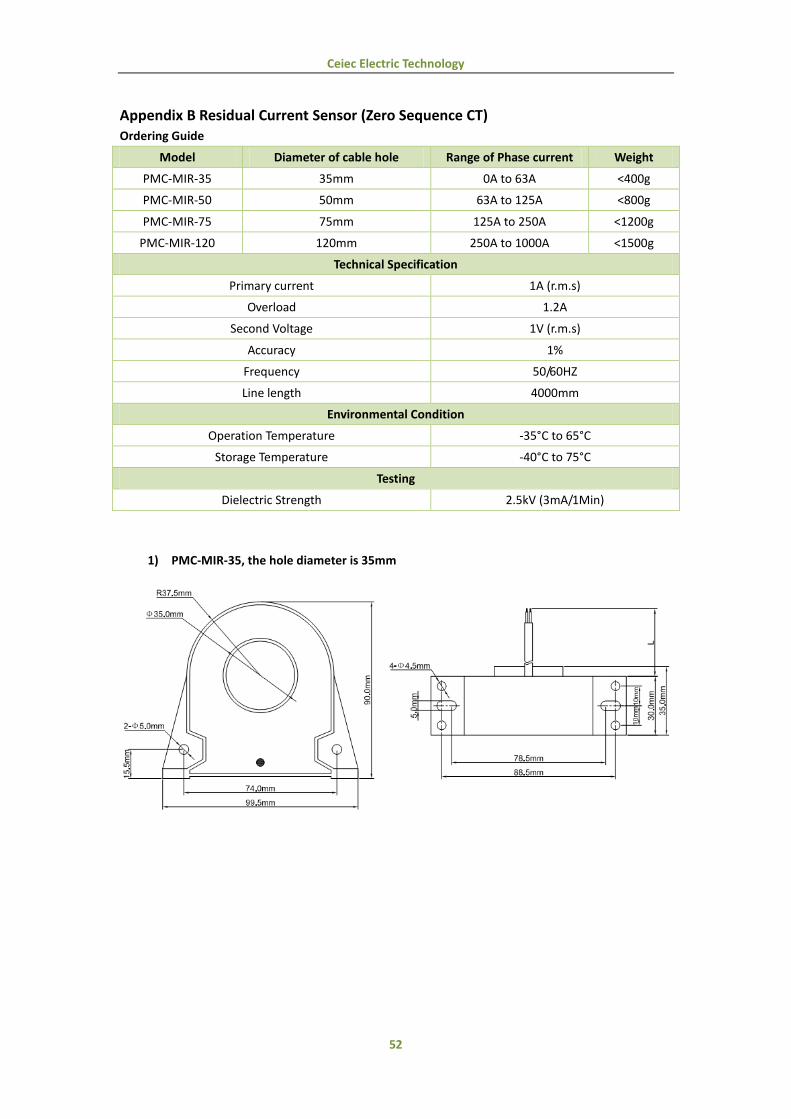
Ceiec Electric Technology
52
Appendix B Residual Current Sensor (Zero Sequence CT) Ordering Guide
Model Diameter of cable hole Range of Phase current Weight
PMC-MIR-35 35mm 0A to 63A <400g
PMC-MIR-50 50mm 63A to 125A <800g
PMC-MIR-75 75mm 125A to 250A <1200g
PMC-MIR-120 120mm 250A to 1000A <1500g
Technical Specification
Primary current 1A (r.m.s)
Overload 1.2A
Second Voltage 1V (r.m.s)
Accuracy 1%
Frequency 50/60HZ
Line length 4000mm
Environmental Condition
Operation Temperature -35°C to 65°C
Storage Temperature -40°C to 75°C
Testing
Dielectric Strength 2.5kV (3mA/1Min)
1) PMC-MIR-35, the hole diameter is 35mm

Ceiec Electric Technology
53
2) PMC-MIR-50, the hole diameter is 50mm
3) PMC-MIR-75, the hole diameter is 75mm
4) PMC-MIR-120, the hole diameter is 120mm

Ceiec Electric Technology
54
Appendix C Temperature Sensor
Hoop Model Diameter Range of Hoop Weight
PMC-DN-30 18 to 32mm <=58g
PMC-DN-50 27 to 51mm <=62g
PMC-DN-55 33 to 57mm <=64g
PMC-DN-60 40 to 63mm <=66g
Technical Specification
Material Platinum resistor Pt100
Work Range -40°C to 200°C
Accuracy ±(0.30+0.005|t|)
Line Length 3000mm
Protective Tube Length 30mm
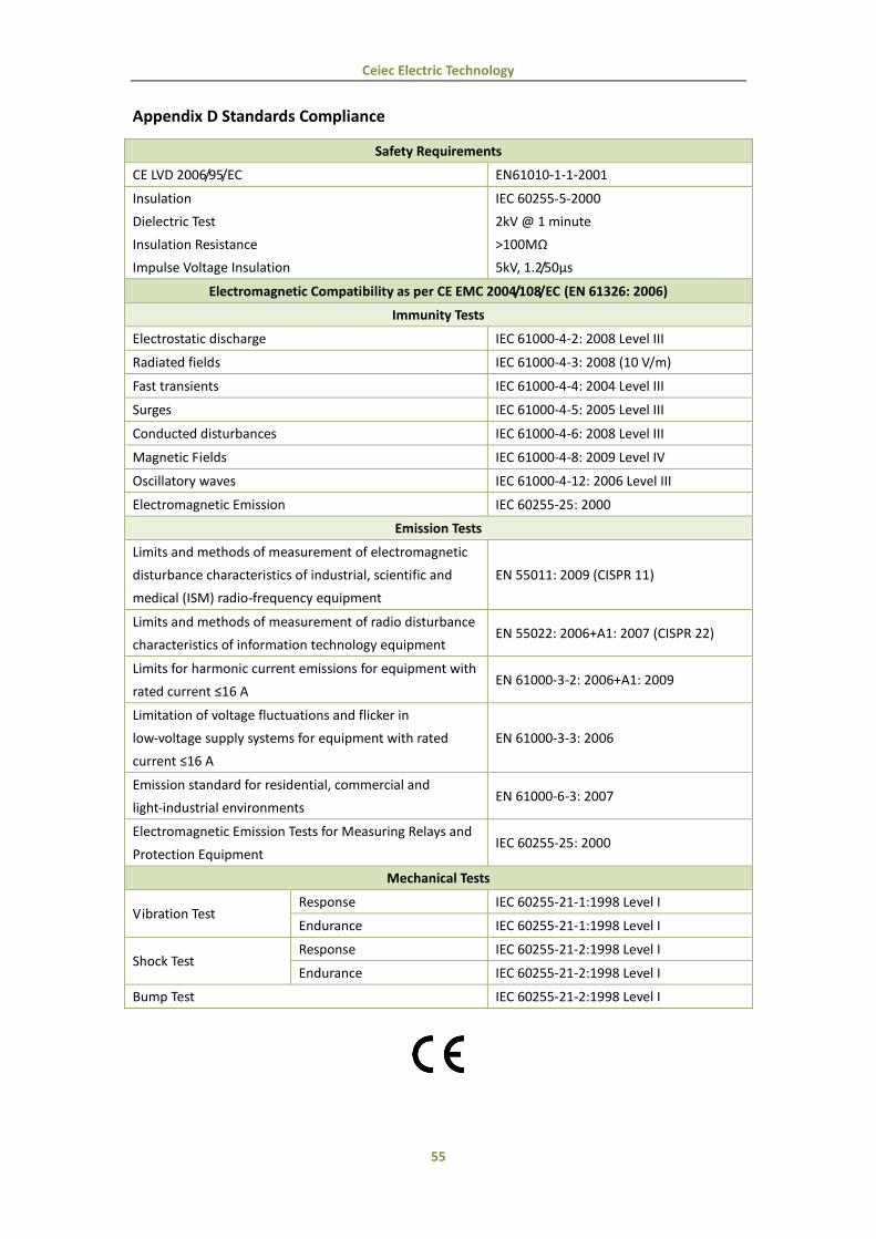
Ceiec Electric Technology
55
Appendix D Standards Compliance
Safety Requirements
CE LVD 2006/95/EC EN61010-1-1-2001
Insulation
Dielectric Test
Insulation Resistance
Impulse Voltage Insulation
IEC 60255-5-2000
2kV @ 1 minute
>100MΩ
5kV, 1.2/50µs
Electromagnetic Compatibility as per CE EMC 2004/108/EC (EN 61326: 2006)
Immunity Tests
Electrostatic discharge IEC 61000-4-2: 2008 Level III
Radiated fields IEC 61000-4-3: 2008 (10 V/m)
Fast transients IEC 61000-4-4: 2004 Level III
Surges IEC 61000-4-5: 2005 Level III
Conducted disturbances IEC 61000-4-6: 2008 Level III
Magnetic Fields IEC 61000-4-8: 2009 Level IV
Oscillatory waves IEC 61000-4-12: 2006 Level III
Electromagnetic Emission IEC 60255-25: 2000
Emission Tests
Limits and methods of measurement of electromagnetic
disturbance characteristics of industrial, scientific and
medical (ISM) radio-frequency equipment
EN 55011: 2009 (CISPR 11)
Limits and methods of measurement of radio disturbance
characteristics of information technology equipment EN 55022: 2006+A1: 2007 (CISPR 22)
Limits for harmonic current emissions for equipment with
rated current ≤16 A EN 61000-3-2: 2006+A1: 2009
Limitation of voltage fluctuations and flicker in
low-voltage supply systems for equipment with rated
current ≤16 A
EN 61000-3-3: 2006
Emission standard for residential, commercial and
light-industrial environments EN 61000-6-3: 2007
Electromagnetic Emission Tests for Measuring Relays and
Protection Equipment IEC 60255-25: 2000
Mechanical Tests
Vibration Test Response IEC 60255-21-1:1998 Level I
Endurance IEC 60255-21-1:1998 Level I
Shock Test Response IEC 60255-21-2:1998 Level I
Endurance IEC 60255-21-2:1998 Level I
Bump Test IEC 60255-21-2:1998 Level I

Ceiec Electric Technology
56
Appendix E Ordering Guide
Contact us
Ceiec Electric Technology Headquarters
8/F, Westside, Building 201, Terra Industrial & Tradepark, Che Gong Miao, Shenzhen, Guangdong,
P.R.China 518040
Tel: +86.755.8341.5187
Fax: +86.755.8341.0291
Email: [email protected]
Web: www.ceiec-electric.com