ce specifications of automobilesdocs.cams.com.au/manual/race/ra27-group-3k-2016-2.pdf ·...
TRANSCRIPT

SPECIFICATION OF AUTOMOBILES – GROUP 3K Last updated: 19/07/16 1 © Confederation of Australian Motor Sport Ltd. All use subject to Conditions of Use at www.cams.com.au
2016 CAMS Manual of Motor Sport
SPECIFICATIONS OF AUTOMOBILES
ALL VEHICLES IN RACES AND OTHER SPEED EVENTS MUST COMPLY WITH THE GENERAL
REQUIREMENTS OF AUTOMOBILES (SEE “GENERAL REQUIREMENTS FOR CARS AND
DRIVERS” IN THE CAMS MANUAL OF MOTOR SPORT).
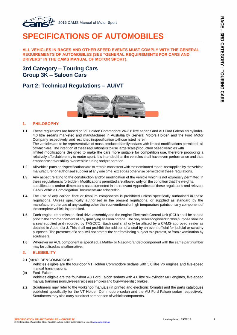
3rd Category – Touring Cars Group 3K – Saloon Cars
PART 1: TECHNICAL REGULATIONS – EA/VN
1. DEFINITIONS
1.1 These regulations are based on VN/VP Holden Commodore V6 3.8 litre sedans and EA/EB Ford Falcon six-
cylinder 3.9 litre sedans, and components from said vehicles marketed and manufactured in Australia by
General Motors Holden and the Ford Motor Company during the period 1988 to 1993 and restricted in
specification to those listed herein.
The vehicles are to be representative of mass produced family sedans with limited modifications permitted,
all of which are designed to make the cars more suitable for competition use. The intention of these regulations
is to emphasise driver ability in a production based vehicle with limited modifications permitted, therefore
producing a relatively affordable entry to motor sport.
1.2 All vehicle parts and specifications are to remain consistent with the nominated model as supplied by the vehicle
manufacturer or authorised supplier at any one time except as otherwise permitted in the present regulations.
1.3 Any aspect relating to the construction and/or modification of the vehicle which is not expressly permitted in
these regulations is forbidden. Modifications permitted are allowed only on the condition that the weights,
specifications and/or dimensions mentioned on the relevant CAMS Vehicle Recognition Document are adhered
to.
1.4 The use of any carbon fibre or titanium components is prohibited unless specifically authorised in these
regulations. Unless specifically authorised in the present regulations or supplied as standard by the
manufacturer, the use of any coatings other than conventional or high temperature paints on any component of
the complete vehicle is prohibited.
1.5 Each engine, engine Electronic Control Unit (ECU), transmission and final drive assembly shall be sealed prior
to the commencement of any official practice, qualifying session or race. The only seal recognised for this
purpose shall be a seal supplied and recorded by The Australian Saloon Car Company Pty Ltd (TASCCO).
Each seal shall only be affixed by a CAMS-approved sealer as detailed in Appendix J. This shall not prohibit the
addition of a seal by an event official for judicial or scrutiny purposes. The presence of a seal will not protect
the car from being subject to a protest, or from examination by scrutineers.
1.6 Wherever an ACL component is specified, a Mahle- or Nason-branded component with the same part number
may be utilised as an alternative.
2. ELIGIBILITY
2.1
(a) Holden Commodore
Vehicles eligible are the four-door VN/VP Holden Commodore sedans (non-IRS) with 3.8 litre V6 engines, five-
speed (T5) manual transmissions, and four-wheel disc brakes. The eligible vehicles are described by the
manufacture VIN prefix 6H8VNK19, 6H8VNL19 and 6H8VNX19, 6H8VPK19, 6H8VPL19.
(b) Ford Falcon
Vehicles eligible are the four-door EA/EB (Series 1 EB only) Ford Falcon sedans with 3.9 litre six-cylinder MPI
engines, five-speed (T50D) manual transmissions and four-wheel disc brakes. The eligible vehicles are
described by the manufacture identification as “Prefix body code” JG23/25/32/34/SW. Model numbers 18733,
18933, 18133, 18734, 18934, 18134, 18737, 18937, 18132.
2.2 Scrutineers may refer to the workshop manuals and the parts catalogues published by General Motors-Holden
and the Ford Motor Company of Australia, specifically for the VN/VP Holden Commodore sedan and the EA/
EB Ford Falcon sedan respectively. Scrutineers may also carry out direct comparison of vehicle components.
RA
CE
– 3R
D C
AT
EG
OR
Y : T
OU
RIN
G C
AR
S

SPECIFICATION OF AUTOMOBILES – GROUP 3K Last updated: 19/07/16 2 © Confederation of Australian Motor Sport Ltd. All use subject to Conditions of Use at www.cams.com.au
3. COACHWORK
3.1 External body trim (decorations) e.g., side protection mouldings may be removed. Where the vehicle was
originally equipped with external embellishments which may have an aerodynamic effect, such as spoilers,
wings, skirts etc., these must be removed. Additional fastening bolts may be added to the trailing edge of the
front bumper facia, and the front of the rear bumper facia. Said bolts must be for securing of bumper only.
3.2 (a) The following interior trim and fittings may be removed:
• hood and pillar linings and sun visors
• arm rests
• centre console
• parcel shelf covering
• spare wheel and jack
• pinch weld mouldings
• door opening seals
• windscreen washer reservoir, hoses and jets.
(b) The following interior trim and fittings must be removed:
• the spare wheel and jack
• floor coverings including underfelt and deadener material.
The original door trims may be replaced with flat metal trims; e.g., fabricated from sheet aluminium. The door
trims must be fastened with screws and be readily removable.
It is permitted to remove the lower dashboard panels and glove box to enable the fitment of the safety cage.
The original dashboard crash pad must be retained and all cables, wiring and ducting must be secured in a
neat and tidy fashion.
3.3 It is permitted to remove all heater and air conditioning components.
3.4 The driver’s seat must be replaced by one complying with Schedule C (refer “General Requirements for Cars and
Drivers” in the CAMS Manual of Motor Sport); all other seats must be removed.
3.5 The complete steering wheel assembly may be replaced by one that complies with Schedule B. It is permitted
to weld an adaptor to the original steering shaft to facilitate the fitment of a quick-release steering wheel
assembly.
When a quick-release steering wheel assembly is fitted, the original upper steering shaft (column) length shall be
maintained (±50mm). The quick-release steering wheel assembly adaptor shall not exceed 75mm in length.
3.6 A footrest may be fitted to the left of the clutch pedal. A floor covering of anti-slip type may be fixed to the
floor of the driver’s compartment, forward of the driver’s seat. Replacement pedal pads are permitted. A clutch
pedal stop may be fitted.
3.7 A front strut brace may be fitted between the front suspension towers. If fitted, the strut brace shall be attached
by bolting only at the suspension towers.
3.8 It is permitted to cut a hole in the passenger floor well for the fitment of a Dorian transmitter holder in accordance
with Appendix A of these regulations.
3.9 The edges of the mudguard panels may be folded back if they protrude inside the wheel housing. Plastic wheel
arch splash guards may be removed.
3.10 The windscreen may incorporate electric heating elements.
3.11 All bodywork including any subsequent repair of race-day damage shall be to a tradesman-like standard and
must permit the vehicle to be presented in as near to original condition as is possible and is subject to the
approval of the Chief Scrutineer.
3.12 It is permitted to strengthen the original Commodore panhard bar mounting bracket on the bodyshell.
3.13 The original primary bonnet fasteners and release mechanisms must be removed and an adequate alternative
retention system is must be fitted in accordance with Schedules B and C (refer “General Requirements for Cars
and Drivers” in the CAMS Manual of Motor Sport). Boot lid fasteners may be removed provided an alternative
closing system is fitted.
3.14 It is permitted to relocated the interior door opening devices to allow for the fitment of roll over protection. The
interior door opening mechanisms must remain functional.
4. SUSPENSION
4.1 The following specified components must be utilised in each respective vehicle. All such components must be
supplied by Pedders Suspension and be identifiable by the Pedders Suspension part number:
• road springs
• strut inserts and Suspension dampers
• adjustable strut upper insulating blocks **
• stabiliser bars
• panhard bar
• front camber adjustment kit (Falcon) ***.
** It is permitted to use K-Mac adjustable strut upper insulating blocks. It is permitted to fit a Pedders
stabiliser bar link rod kit.
*** It is permitted to fit XF Falcon eccentric camber adjustment pins to the EA/EB Falcon models.
RA
CE
– 3R
D C
AT
EG
OR
Y : T
OU
RIN
G C
AR
S

SPECIFICATION OF AUTOMOBILES – GROUP 3K Last updated: 19/07/16 3 © Confederation of Australian Motor Sport Ltd. All use subject to Conditions of Use at www.cams.com.au
4.2 It is permitted to fit adjustable front suspension tension rods, supplied by Croft Engineering. It is permitted to fit
Noltec® offset lower/inner control arm bushes. Ford part No. N52550 – Holden part No. N52490.
It is permitted to fit Urethane bushes to the K-Frame for the tension rods. It is permitted to fit urethane bushes
to the rear of the tension rod where they pass through the suspension arm.
4.3 The maximum negative camber at each front wheel is 5°. On the Commodore, it is permitted to reposition the
lower control arm inner pivot point on the “K” frame an equal amount on both sides, on the same horizontal
plane as the original pivot points in accordance with Appendix B of these regulations.
4.4 It is permitted to remove the original top rear spring insulators. Solid spacers of uniform section may be fitted
between the springs and their unmodified mounting points to achieve a desired ride height, with a maximum
spacer/s thickness of 30mm in total on any one spring.
4.5 It is permitted to fit an oil cooler to the power steering system. It is permitted to vent the power steering fluid
reservoir into a catch tank. It is permitted to remove or render the stabiliser bars and associated hardware
inoperative.
4.6 It is permitted to remove or render the stabiliser bars and associated hardware inoperative.
5. BRAKES
5.1 Both the Commodore and the Falcon must use ferrous front brake rotors with the maximum dimensions of
330mm diameter and 32mm thickness. Brake hats are free. For both EA and VN models it is permitted to use
either the PBR-C4 twin piston front caliper, or the six piston Wilwood front brake caliper - Wilwood part number
120-13267-N (RH) and 120-13267-N (LH).
5.2 Original brake flexible hoses may be replaced by others of adequate strength and quality.
5.3 It is permitted to fit a variable brake pressure valve in the rear brake line. This valve may be mounted within reach
of the driver whilst racing. The rear brake line may be modified to accomplish the fitment.
5.4 The brake pads are free provided that the contact surface area of the pad is not greater than that supplied by
the manufacturer of the caliper assembly. The maximum permitted thickness of the backing plate is 6mm.
The retention of the pad assembly in the caliper must be by the method prescribed by the manufacturer of the
caliper assembly.
5.5 Brake rotor protection shields may be modified or removed for brake cooling. If removed a brake hose support
bracket must be fitted. The handbrake and all associated components may be disconnected or removed.
5.6 It is permitted to fit one flexible pipe (maximum 100mm internal diameter) to carry air to each front brake. All air
must be supplied through the air intake ducts and be for brake cooling only as described in Appendix A, Part 1
of these regulations. The front air intake ducts must be located in the front bumper bar and be a maximum
diameter of 100mm. Fittings at the exhaust end of the pipe are free, subject to no modifications being made to
other components to allow fitment of the ducting. The fitment of rear cooling ducts is free.
5.7 Master cylinders: The master cylinder must be as supplied by the manufacturer, save that the bore size and
valving is free. Sleeving is permitted.
5.8 Anti-lock braking systems (ABS) must be removed.
6. ELECTRICAL
6.1 The location of the battery is free, save that it may not be located in the habitacle. The maximum battery size
must be that which can fit the standard battery tray in each vehicle. The battery box must be a maximum
weight of 2kg and be permanently fastened.
6.2 It is permitted to remove the central locking components, radio and the interior lights and any non-functional
electrical wiring, modules and connectors. It is permitted to replace the wiring loom save that the following
electrical equipment remains operational – windscreen wipers, head and tail lights, stop lights including the high-
level brake light. A high-level brake light is mandatory. Fuses and a master electrical circuit breaker may be
added to the electrical system. Data logging shall be limited to lap liming, drive line and engine function only.
The use of telemetry is prohibited.
6.3 Supplementary switches and instruments may be fitted. The original instrument cluster may be removed.
6.4 The only ECU permitted is the sealed model 4424 Stinger®, as supplied by Engine Management Systems Pty
Ltd (EMS). The specified ECU must be located in the front passenger area and be readily accessible. The
original ECU connector (plug) in the vehicle wiring harness (as fitted by the manufacturer) must be removed.
It is permitted to remove the map sensor and idle control motor; a blanking plate must be fitted to the resulting
apertures.
It is permitted to relocate the ignition coil (Falcon) to the left hand inner mudguard skirt.
It is permitted to fit an approved data storage device, including a multi-display dash with only ability to store
vehicle data.
Any device which has capability of outputting any signal or data to the vehicle ECU, or that is capable of altering
the vehicle engine functions in any way, irrespective of whether it is being used or not will be considered to be
an ECU and therefore in breach of these regulations. Any such unit is specifically not
permitted in the vehicle during competition. The data storage unit must be mounted in a visually accessible
position.
The software for the data storage device must not show any pin allocations set-up to read sensors other
RA
CE
– 3R
D C
AT
EG
OR
Y : T
OU
RIN
G C
AR
S

SPECIFICATION OF AUTOMOBILES – GROUP 3K Last updated: 19/07/16 4 © Confederation of Australian Motor Sport Ltd. All use subject to Conditions of Use at www.cams.com.au
than those permitted.
The only approved data storage devices are as per the following: AIM MXL Strata, Pista Pro Data, Video VBOX
Lite acquisition systems, MoTeC ADL-8/CDL3, EMS mini logger that is supplied with the Stinger ECU and
Synergy Series EDL-7 Race Dash.
It is permitted to fit an ignition module supplied by EMS. 6.5 The maximum engine rpm for both the EA/EB Falcon and the VN/VP Commodore is 5800rpm. Maximum
engine rpm must be set and sealed in the control Stinger 4424 ECU as supplied by Engine Management Systems P/L (EMS) for the specific model.
7. FUEL & FUEL TANKS
Only Commercial Fuel as defined by CAMS may be used. Refer Schedule G. With the exception of ambient
atmospheric air, no other substance may be added to the intake charge of the engine.
It is mandatory that a Jiffy-Tite 2000 series fuel-sampling coupling (female coupling only) be fitted to the fuel
system (under bonnet).
The Technical Commissioner and/or scrutineers may require a fuel sample at any time.
Original equipment fuel injectors may be replaced by other interchangeable units. Fuel pressure must not
exceed 400kPa.
The main fuel tanks must be as provided by the manufacturer. The fuel tank may be filled with anti-spray foam.
Fuel caps are free. Baffling of the fuel tank is permitted.
It is permitted to fit one anti-surge fuel tank of 5.5 litre maximum capacity and one additional electric fuel pump.
The anti-surge tank and pump must only be fitted in the rear of the vehicle.
If the anti-surge tank/pump kit components are mounted inside the rear luggage compartment (boot) area, a
fireproof and liquid-proof bulkhead must separate the cockpit from the rear luggage compartment.
8. TYRES & RIMS
8.1 Each automobile shall only be fitted with Bridgestone Potenza RE11 Type SR2 235/50R16 or 235/45R17 tyres.
8.2 Wheels are free save that they must be 16” x 8” or 17” x 8”, and when fitted, the vehicle must comply with the
track dimensions detailed in Article 14.
The minimum weight for each wheel rim is 9kg for 16 inch and 10kg for 17 inch. All four wheels fitted must be of
the same style and size.
8.3 At the commencement of practice, qualifying or racing the tread, shall be not less than 1.5mm depth when
measured at any point, save that this does not apply to the shoulder of the tyre.
9 (A). ENGINE – VN/VP HOLDEN COMMODORE
9.1 (a) It is only permitted to use the Holden V6 engine as fitted to the Commodore VN Series 1 and 2, and Commodore
VP Series 1.
9.2 (a) Cylinder heads: It is permitted to machine the valve seats in the cylinder heads at 45° with the overcut
angles/radii being free. The valve seat faces must be re-cut at 45°. Back cutting of the valves is permitted. The
maximum inlet valve size is 43.56mm and the exhaust is 37.97mm.
It is permitted to reclaim the valve seats as per the manufacturer’s specifications, including through the use of a
seat insert.
It is permitted to refurbish valve guides using thin wall type valve guides (K-Line or equivalent).
It is permitted to machine the cylinder head face parallel to the original to obtain a minimum combustion
chamber volume of 36cc for ACL part number 3800 pistons and 37.5cc for ACL part number 9380 pistons and
Precision Parts Australia part number PHO38006040MMS pistons.
It is permitted to machine the ports from the valve seat to the untouched valve guide boss with the largest
diameter of any taper at the valve seat. All machine work must be concentric with the centre line of the original
valve guide.
The use of hardened or machined valve collets and retainers is permitted.
The valve springs are free subject to there being a maximum of two springs per valve. It is permitted to fit shims
under the valve springs.
It is permitted to machine the valve spring seats to obtain the correct valve spring installed height. It is
permitted to de-burr the valve spring seats locally after machining, provided it is to industry standards. Other
hand or mechanical finishing of the valve spring seats is not permitted. 9.3 (a) Camshaft: All cars must be fitted with the Crow Cams part number SCRA3800 camshaft or a Clive Cams part
number SSTC3800. Each camshaft must match the Crow Cams cam doctor report specific for that camshaft.
It is permitted to remove the balance shaft and gears.
The timing chain and gears are free. The camshaft phase angle in relation to the crankshaft is free.
9.4 (a) Crankshaft & rods: The crankshaft journals may be reground a maximum of 1.0mm undersize, with a
maximum stroke of 86.36mm. The crankshaft minimum weight shall be 16.00kg bare (VN) or 15.50 (VP).
The connecting rods may be re-sized and machined to provide additional side clearance and to attain the
correct piston height, and to facilitate the use of replacement rod bolts. The connecting rod minimum weight is
640.0 grams.
Main and connecting rod bearings are free save that they must maintain the original external dimensions. It is
permitted to dowel the flywheel to the crankshaft. 9.5 (a) Balancing: All rotating and reciprocating components may be balanced by the removal of metal only from the
locations so provided by the manufacturer.
Piston balancing will be achieved by removal of metal from the underside of the piston only.
RA
CE
– 3R
D C
AT
EG
OR
Y : T
OU
RIN
G C
AR
S

SPECIFICATION OF AUTOMOBILES – GROUP 3K Last updated: 19/07/16 5 © Confederation of Australian Motor Sport Ltd. All use subject to Conditions of Use at www.cams.com.au
The flywheel may be machined on the friction surface only, and balanced to a minimum weight of 9.50kg. It is
permitted to use a Powerbond torsional damper (Harmonic balancer).
The minimum torsional damper weight shall be 3.20kg.
9.6 (a) Intake manifold: The intake manifold may be glass bead blasted. It may be machined on the cylinder head
and block mating faces to obtain correct fitment to the engine.
Match porting of the inlet manifold ports for a maximum distance of 6mm from each left and right hand face is
permitted in accordance with Appendix E.
The original air cleaner box must be removed and replaced with a cone-type replacement air element directly
attached to the unmodified front snorkel tube mounted in its original location. The PVC system must be
removed, and the resulting holes in the inlet manifold and throttle body must be mechanically sealed. 9.7 (a) Lubrication: Baffling of the sump is permitted, save that the external appearance of the sump is as supplied
by the manufacturer as standard.
The oil pressure relief valve spring may be shimmed.
It is permitted to fit an engine oil cooler provided that the bodywork is not altered for the purpose of its fitment,
nor may it be fitted outside the confines of the standard bodywork. 9.8 (a) Engine block: The engine block may be re-bored to a maximum of 1.0mm oversize.
The only pistons permissible shall be ACL part number 6MKRY3800 or part number 6MKRY9380 and
Precision Parts Australia part number PHO38006040MMS pistons. The minimum permissible piston weight,
with gudgeon pin, is 555g.
The piston rings shall comply with the following requirements:
• There must be two compression rings and a segmented oil ring on each piston;
• ‘Gapless’ piston rings are not permitted;
• The piston ring gaps may be adjusted, however the ends of each compression ring must be parallel to the
centre line of the cylinder bore.
Where ACL pistons are fitted, piston ring pack ACL part number MP1727 (for 6MKRY3800 pistons) or M1812
(for 6MKRY9380 pistons) shall be used.
The engine block face may be machined in a plane perpendicular to the cylinder bores. The pistons must not
protrude from the engine block face at TDC.
For the sole purpose of achieving equal piston deck heights, it is permitted to machine a minimal amount of
material from the top surface (crown) of any four (4) pistons per engine.
It is permitted to fit extra engine breathers, but all breathers must discharge to a catch tank that is vented to the
atmosphere.
9.9 (a) Head gasket: The cylinder head gaskets must be of standard configuration type and dimensions for the
model with a minimum thickness of 0.95mm. 9.10 (a) Valve train: It is permitted to shim the rocker arm pedestals to obtain the correct tappet settings.
9.11 (a) It is permitted to fit an external timing pointer to the timing chain cover. It is permitted to slot the crank angle
sensor to permit timing adjustment.
9 (B). ENGINE – EA/EB FORD FALCON
9.1 (b) It is only permitted to use the Ford 3.9 litre multi-point electronic fuel injected engine as fitted to the Falcon EA
and EB Series 1.
9.2 (b) Cylinder head: It is permitted to machine the valve seats in the cylinder head at 45° with the overcut and
undercut angles/radii being free. The valve seat faces must be re-cut at 45°. Back cutting of the valves is
permitted. The maximum inlet valve size is 47.0mm and the exhaust is 39.0mm.
It is permitted to reclaim the valve seats as per the manufacturer’s specifications, including through the use of a
seat insert.
It is permitted to machine the cylinder head face to obtain a minimum combustion chamber volume of 55cc (for
6MKRY2809 and 6MKRY3900 pistons) and 57cc for 6MKRY9390 pistons and Precision Parts Australia part
number PFO39006040MMS pistons. Angle milling is not permitted.
It is permitted to machine the ports from the valve seat to the untouched valve guide boss with the largest
diameter of any taper at the valve seat. All machine work must be concentric with the centre line of the original
valve guide.
The following dimensions must be respected:
• Valve guide total length: minimum 62.2mm.
• Valve guide protrusion: maximum 19.1mm above guide boss on top of cylinder head.
The use of hardened and/or machined collets and retainers is permitted. The valve springs are free subject to
there being a maximum of two springs per valve. It is permitted to fit shims under the valve springs.
It is permitted to machine the valve spring seats to obtain the correct valve spring installed height. It is
permitted to de-burr the valve spring seats locally after machining, provided it is to industry standards. Other
hand or mechanical finishing of the valve spring seats is not permitted.
It is permitted to use camshaft rocker arms as fitted to Ford Falcon six-cylinder models EA to EF.
9.3 (b) Camshaft: The camshaft shall be Crow Cams part number SCRA3900 or Clive Cams part number SSTC3900.
Each camshaft must match the Crow Cams cam doctor report specific for that camshaft.
The timing chain and gears are free. The camshaft phase angle in relation to the crankshaft is free.
9.4 (b) Crankshaft & rods: The crankshaft journals may be reground to a maximum 1.0mm undersize with a
maximum stroke of 99.31mm. The crankshaft minimum weight shall be 25.75kg.
The connecting rods may be re-sized and machined to provide additional side clearance and to attain the
correct piston height, and to facilitate the use of replacement rod bolts. The connecting rod minimum weight is
610g.
RA
CE
– 3R
D C
AT
EG
OR
Y : T
OU
RIN
G C
AR
S

SPECIFICATION OF AUTOMOBILES – GROUP 3K Last updated: 19/07/16 6 © Confederation of Australian Motor Sport Ltd. All use subject to Conditions of Use at www.cams.com.au
Main and connecting rod bearings are free save that they must maintain the original external dimensions.
9.5 (b) Balancing: All rotating and reciprocating components may be balanced by the removal of metal only from the
locations so provided by the manufacturer.
Piston balancing will be achieved by removal of metal from the underside of the piston only.
The flywheel may be machined on the friction surface only, and balanced to a minimum weight of 11.00kg. The
minimum torsional damper weight shall be 4.40kg. 9.6 (b) Intake manifold: The intake manifold may be glass bead blasted. The manifold may be machined on the
cylinder head mating face to match the cylinder head and thus obtain correct fitment to the engine.
Match porting of the inlet manifold ports for a maximum distance of 6mm from the mounting face is permitted
as per Appendix E. The inlet manifold must be Ford part number 87DA9425.
The original air cleaner box must be removed and replaced with a cone-type replacement air element attached
directly to the unmodified front snorkel tube, elbow and external support bracket. 9.7 (b) Lubrication: Baffling of the sump is permitted. Save that the external appearance of the sump is as supplied
by the manufacture as standard.
The oil pressure relief valve spring may be shimmed.
It is permitted to fit an engine oil cooler provided that the bodywork is not altered for the purpose of its fitment,
nor may it be fitted outside the confines of the standard bodywork. 9.8 (b) Engine block: The engine block may be rebored to a maximum oversize of 1.0mm.
The only pistons permissible shall be ACL part number 6MKRY2809, 6MKRY3900 or 6MKRY9390 and
Precision Parts Australia part number PFO39006040MMS. The minimum weight of each piston and gudgeon
pin shall be 600 grams for 6MKRY2809 pistons, 562g for 6MKRY3900 pistons or 558g for 6MKRY9390 and
PFO39006040MMS pistons.
The piston rings shall comply with the following requirements:
• There must be two compression rings and a segmented oil ring on each piston;
• ‘Gapless’ piston rings are not permitted;
• The piston ring gaps may be adjusted, however the ends of each compression ring must be parallel to the
centre line of the cylinder bore.
Where ACL pistons are fitted, piston ring pack ACL part number MP1717 shall be used.
The engine block face may be machined in a plane perpendicular to the cylinder bores. The pistons must not
protrude from the engine block face at TDC.
For the sole purpose of achieving equal piston deck heights, it is permitted to machine a minimal amount of
material from the top surface (crown) of any four (4) pistons per engine.
It is permitted to fit extra engine breathers, but all breathers must discharge to a catch tank vented to the
atmosphere.
9.9 (b) Cylinder head gasket: The cylinder head gasket must be of standard configuration type and dimensions for
the model with a minimum thickness of 0.70mm. 9.10 (b) It is permitted to fit an additional idler pulley to support the power steering pump drive belt.
10. EXHAUST
The exhaust system is free from the exit of the cylinder head. It is permitted to modify the pinch weld flanges
under the sill panel (locally) to facilitate the exit of the exhaust.
The exhaust system may be coated with materials other than paint (e.g., ceramic/high-temperature coatings).
11. COOLING SYSTEM
11.1 ENGINE: It is permitted to remove the original fan and fit a replacement electric radiator fan. The fan shroud
may be removed.
The thermostat is free as is the control system of the fan.
The original radiator may be replaced provided that the original mounting points are utilised, the front plane of
the radiator remains in the same location as the original and that no modifications are carried out for its
fitment. The radiator design, construction and fitment must serve no purpose other than to cool the engine
coolant. A protective mesh screen may be fitted in front of the radiator.
A water filter may be fitted to the top radiator hose.
11.2 TRANSMISSION: It is permitted to fit a transmission lubricant cooler, filter and pump. The cooler, filter and
pump must be fitted beneath the vehicle in the rear “seat well” area (in accordance with Appendix F of these
regulations) which must be utilised only for the cooling of the transmission lubricant.
It is permitted to drill and tap a thread into the transmission casing to accommodate the cooler return line.
12. TRANSMISSION
12.1 GEARBOX: The only permitted gear ratios are:
Commodore Falcon
1st 3.25:1 3.50:1 or 3.25:1
2nd 1.99:1 2.14:1 or 1.99:1
3rd 1.29:1 1.39:1 or 1.29:1
RA
CE
– 3R
D C
AT
EG
OR
Y : T
OU
RIN
G C
AR
S

SPECIFICATION OF AUTOMOBILES – GROUP 3K Last updated: 19/07/16 7 © Confederation of Australian Motor Sport Ltd. All use subject to Conditions of Use at www.cams.com.au
4th 1.00:1 1.00:1
5th 0.72:1 0.72:1 or 0.78:1 or 0.83:1
Reverse 3.15:1 3.39:1
VN/VP Commodore: Only the T5 manual five-speed Borg-Warner gearbox as fitted by GMH as original
equipment may be used (Production option M78-V6).
EA/EB Falcon: Only the T50D (part number 87DA-7003-AA, 87DA-7003-AB, 90DA-7003-AA, 91DA-7003-
BA) It is permitted to use the T5 five-speed manual five-speed gearbox as fitted by Ford Motor Company as
original equipment in the XF/EA and EB/AU model Falcon vehicles. It is permitted to use a 0.83:1 5th gear ratio. may
be used. Internal gearbox components are free save that they shall perform the original operation of the T5
for the Holden Commodore and T50D for the Ford Falcon; ie, synchromesh operation. Dog-tooth engagement
is prohibited.
It is permitted to use non-genuine rotating gearbox components as supplied by Pfitzner Performance Gearbox.
Falcon part no. SL-T5-34-S-F; Commodore part no. SL-T5-34-S-C.
It is permitted to replace the original rear countershaft bearing and primary shaft bearing retainers with an
aftermarket unit.
It is permitted to carry out local modification of the gearbox casing to allow the fitment of alternate bearings.
A circular hole of 50mm diameter must be made in the bottom of the bell housing to facilitate inspection of the
clutch assembly and flywheel.
12.2 The breathers for the gearbox and the final drive assembly may have extensions fitted by way of a length of
tubing.
12.3 REAR AXLE ASSEMBLY: The differential action of the rear axle must be disabled. A 28-spline “mini spool” may
be fitted to the existing differential casing or a full spool may replace the original differential carrier assembly.
It is permitted to fit mechanically-identical replacement rear axles.
The final drive ratio must be 3.45:1 (tooth count 38:11) for both cars. Rear axle bearing retainer plates are free.
12.4 CLUTCH: The clutch assembly may be replaced by authorised parts (refer article 15), save that the pressure
plate assembly cover must be of steel construction.
It must use a single driven plate; said driven plate must be of the same diameter as the original unit as fitted by
the manufacturer.
12.5 It is permitted to fit an aftermarket gear shifter subject to the original shift pattern being retained.
13. SAFETY CAGE
The safety cage design must be in compliance with Schedule J (refer “General Requirements for Cars and
Drivers”). The minimum thickness of all safety cage members shall be 2.5mm. It is not permissible to use
additional members which would require CAMS homologation.
No part of the safety cage may penetrate the front or rear firewall, save for mounting bolts. The safety cage
must be attached to the bodyshell at only those locations shown in drawings J-12, J-29 to J-46, or to the “A”
and “B” pillars. No other connection to the bodyshell is permitted.
14. WEIGHTS AND DIMENSIONS
Commodore Falcon
14.1 Minimum racing weight: 1350kg 1430kg
14.2 Track: Front 1780mm maximum 1875mm maximum
Rear 1485mm 1545mm
14.3 All fully-sprung components of the vehicle, in as raced condition (excluding the complete exhaust system) shall
be at least 100mm above the ground.
14.4 Ballast may be used to achieve the minimum weight requirements, and, if used, shall comply with CAMS
requirements.
14.5 The maximum track dimension shall be the distance between the outermost parts of the walls of each tyre on
the same axle measured in line with the axle centreline as presented for competition.
RA
CE
– 3R
D C
AT
EG
OR
Y : T
OU
RIN
G C
AR
S

SPECIFICATION OF AUTOMOBILES – GROUP 3K Last updated: 19/07/16 8 © Confederation of Australian Motor Sport Ltd. All use subject to Conditions of Use at www.cams.com.au
15. AUTHORISED PARTS
The following service parts may be from any source provided that their use does not result in unauthorised
modification of any other component:
• gaskets
• fasteners
• nuts, bolts, screws and other fasteners
• lamps
• battery
• battery clamp and leads
• fluid filters, engine ancillary drive belts,
water hoses and clamps
• water pump
• idler pulleys
• auxiliary gauges
• spark plugs and leads
• coil packs
• auxiliary bonnet fasteners
• gear shifter
• tie rods
• suspension stabiliser bar link pin kits
• clutch pressure plate
16. NON-GENUINE PARTS
• clutch driven plate
• clutch throw out bearing
• seals
• engine cylinder head valves
• bearings
• gearbox, rear axle and differential bearings
• differential gears
• head and tail light assemblies
• brake caliper kits
• shims and spacers
• universal joints and CV joints
• wheel bearings
• fuel pumps
• valve rocker covers
• valve guides and pushrods
• suspension bushes
• brake rotors and rear brake caliper mounting
brackets and harmonic balancers.
The following replacement parts must be mechanically, functionally and dimensionally identical replacement for
the original parts:
tie rod ends water pump
ball joints window glass
17. AMENDMENTS
CAMS reserves the right to amend these regulations at any time, including, but not limited to, such items as
may affect the performance parity between the vehicle models.
Appendix A
Front Brake Duct Installation
This is an EA/EB front bar example
100mm vertical
Ford 1 Ford 2
200mm maximum horizontal
This is a VN/VP front bar example
100mm vertical
Commodore 1 Commodore 2
200mm maximum
RA
CE
– 3R
D C
AT
EG
OR
Y : T
OU
RIN
G C
AR
S
SPECIFICATION OF AUTOMOBILES – GROUP 3K Last updated: 19/07/16 9 © Confederation of Australian Motor Sport Ltd. All use subject to Conditions of Use at www.cams.com.au
2016 CAMS Manual of Motor Sport
SPECIFICATIONS OF AUTOMOBILES
ALL VEHICLES IN RACES AND OTHER SPEED EVENTS MUST COMPLY WITH THE GENERAL
REQUIREMENTS OF AUTOMOBILES (SEE “GENERAL REQUIREMENTS FOR CARS AND
DRIVERS” IN THE CAMS MANUAL OF MOTOR SPORT).
3rd Category – Touring Cars Group 3K – Saloon Cars
Part 2: Technical Regulations – AU/VT
1. PHILOSOPHY
1.1 These regulations are based on VT Holden Commodore V6-3.8 litre sedans and AU Ford Falcon six cylinder-
4.0 litre sedans marketed and manufactured in Australia by General Motors Holden and the Ford Motor
Company respectively, and restricted in specification to those listed herein.
The vehicles are to be representative of mass-produced family sedans with limited modifications permitted, all
of which are. The intention of these regulations is to use large scale production based vehicles with
limited modifications designed to make the cars more suitable for competition use, therefore producing a
relatively affordable entry to motor sport. It is intended that the vehicles shall have even performance and thus
emphasise driver ability over vehicle tuning and preparation.
1.2 All vehicle parts and specifications are to remain consistent with the nominated model as supplied by the vehicle
manufacturer or authorised supplier at any one time, except as otherwise permitted in these regulations.
1.3 Any aspect relating to the construction and/or modification of the vehicle which is not expressly permitted in
these regulations is forbidden. Modifications permitted are allowed only on the condition that the weights,
specifications and/or dimensions as documented in the relevant Appendices of these regulations and relevant
CAMS Vehicle Homologation Documents are adhered to.
1.4 The use of any carbon fibre or titanium components is prohibited unless specifically authorised in these
regulations. Unless specifically authorised in the present regulations, or supplied as standard by the
manufacturer, the use of any coating other than conventional or high temperature paints on any component of
the complete vehicle is prohibited.
1.5 Each engine, transmission, final drive assembly and the engine Electronic Control Unit (ECU) shall be sealed
prior to the commencement of any qualifying session or race. The only seal recognised for this purpose shall be
a seal supplied and recorded by TASCCO. Each seal shall only be affixed by a CAMS-approved sealer as
detailed in Appendix J. This shall not prohibit the addition of a seal by an event official for judicial or scrutiny
purposes. The presence of a seal will not protect the car from being subject to a protest, or from examination by
scrutineers.
1.6 Wherever an ACL component is specified, a Mahle- or Nason-branded component with the same part number
may be utilised as an alternative.
2. ELIGIBILITY
2.1 (a) HOLDEN COMMODORE
Vehicles eligible are the four-door VT Holden Commodore sedans with 3.8 litre V6 engines and five-speed
manual transmissions.
(b) Ford Falcon
Vehicles eligible are the four-door AU Ford Falcon sedans with 4.0 litre six-cylinder MPI engines, five-speed
manual transmissions, live rear axle assemblies and four-wheel disc brakes.
2.2 Scrutineers may refer to the workshop manuals (in printed and electronic formats) and the parts catalogues
published specifically for the VT Holden Commodore sedan and the AU Ford Falcon sedan respectively.
Scrutineers may also carry out direct comparison of vehicle components.
RA
CE
– 3R
D C
AT
EG
OR
Y : T
OU
RIN
G C
AR
S

SPECIFICATION OF AUTOMOBILES – GROUP 3K Last updated: 19/07/16 10 © Confederation of Australian Motor Sport Ltd. All use subject to Conditions of Use at www.cams.com.au
3. COACHWORK
3.1 Each VT Commodore and AU Falcon must be fitted with the specified front bumper fascia and boot lid wing as
per the following:
• Each VT Commodore must be fitted with either a VT - SS front bumper fascia and bootlid wing as fitted to the
Series 1 VT - SS model by GM Holden, or an aftermarket replacement that retains the original external shape,
dimensions and pitch. The original (OEM) mounting/attachment points must be used. It is permitted to fit
a standard VT Holden Commodore front bumper bar providing that it is fitted with VT-SS lower front lip. Only
VT Commodore rocker panel covers as fitted to the non-optioned base model Executive vehicles are permitted. It is permitted to fit a VX-SS Commodore front bumper facia as fitted by GM Holden or an
aftermarket replacement which retains the original external shape.
• Each AU Falcon must be fitted with either an AU XR6 front bumper fascia and bootlid wing as fitted to the
AU XR-6 model by Ford Australia, or an aftermarket replacement that retains the original external shape and
dimensions. The original (OEM) mounting/attachment points must be used. It is permitted to remove the inner
headlights provided that a blanking plate is secured to cover the resulting apertures. It is permitted to remove
the front indicator assemblies. Additional fastening bolts may be added to the trailing edge of the front bumper
fascia, and the front of the rear bumper fascia. Said bolts must be for securing the bumper bars only.
• The only side skirts permitted for both models are the standard model skirts as fitted to the base model
vehicle. The only bonnet and mountings permitted for the AU Falcon shall be as fitted to the AU Falcon Forte series 1 or
XR6 series 2. It is permitted to update the VT Commodore body to a VY model update must be a complete panel
change and include all VY-SS panels and fittings.
3.2 (a) The following interior trim and fittings may be removed:
• hood and pillar linings and sun visors,
• arm rests
• centre console
• parcel shelf covering
• pinch weld mouldings
• door opening seals.
(b) The following interior trim and fittings must be removed:
• the spare wheel and jack
• floor coverings including underfelt and deadener material.
It is permitted to remove the lower dashboard panels and glove box to enable the fitment of the safety cage. The
original dashboard crash pad must be retained and all cables, wiring and ducting must be secured in a neat
and tidy fashion.
3.3 Original interior door trims must be replaced with flat metal trims; ie, fabricated from sheet aluminium. The door
trims must be fastened with screws and be readily removable.
3.4 External body trim (decorations), e.g., side protection mouldings, may be removed
3.5 It is permitted to remove all heater and air conditioning components.
3.6 The driver’s seat must be replaced by one complying with Schedule C (refer “General Requirements for Cars and Drivers” in the CAMS Manual of Motor Sport); all other seats may be removed. It is permitted to remove the
original seat mounting structure to enable the fitment of a transverse cross member seat mounting
as per Appendix J of these regulations.
3.7 The complete steering wheel assembly may be replaced by one that complies with Schedule B. It is permitted
to weld an adapter to the original steering shaft to facilitate the fitment of a quick-release steering wheel
assembly. The VT Commodore upper steering shaft (column) may be replaced with a VY Commodore upper
steering shaft.
When a quick-release steering wheel assembly is fitted, the original upper steering shaft (column) length shall be
maintained (±50mm). The quick-release steering wheel assembly adaptor shall not exceed 75mm in length.
3.8 A footrest may be fitted to the left of the clutch pedal. A floor covering of anti-slip type may be fixed to the floor
of the habitacle, forward of the driver’s seat. Replacement pedal pads are permitted.
3.9 A front strut brace may be fitted between the front suspension towers. This may be added by bolting only, and
must be attached to the body shell only at the suspension towers.
3.10 It is permitted to cut a hole in the passenger floor well for the fitment of a Dorian transmitter holder as per
Appendix A of these regulations.
3.11 The edges of the mudguard panels may be folded where they protrude inside the wheel housing. Plastic wheel
arch splash guards may be removed. The maximum width of each VT Holden Commodore measured between
the outer edges of both front and rear mudguards shall be: front – 1820mm and rear – 1840mm measured at
the axle centre line.
3.12 The windscreen may be replaced by another one of laminated glass, possibly incorporating electric heating
elements. It is permitted to fit aftermarket windscreen demisters.
3.13 All bodywork including any subsequent repair of race-day damage shall be to a tradesman-like standard and
must permit the vehicle to be presented in as near to original condition as possible and is subject to approval by
RA
CE
– 3R
D C
AT
EG
OR
Y : T
OU
RIN
G C
AR
S

SPECIFICATION OF AUTOMOBILES – GROUP 3K Last updated: 19/07/16 11 © Confederation of Australian Motor Sport Ltd. All use subject to Conditions of Use at www.cams.com.au
the Chief Scrutineer.
3.14 The original primary bonnet fasteners and release mechanisms must be removed and an adequate alternative
retention system fitted. The boot lid fasteners may be removed provided an alternative system is provided.
3.15 It is permitted to remove the side indicator lamp assemblies (located at rear of front mudguards), the resultant
hole must be covered or filled.
3.16 It is permitted to remove the VT Commodore rear seat lower mounting bracket.
3.17 It is permitted to re-locate and/or modify the interior door opening devices to allow for the fitment of rollover
protection. The interior door opening mechanisms must remain functional.
4. SUSPENSION & STEERING
4.1 The following specified components shall be utilised in each respective vehicle:
• road springs
• suspension dampers, including strut inserts
Each unit shall be part numbered as per the automobile homologation documents.
The only rear spring permitted for the VT Commodore shall be King Springworks P/L - COM-SAL R/C. The use
of spherical bearing tie-rod ends (rose joints) is prohibited.
4.2 It is permitted to fit an aftermarket suspension stabiliser bar link pin. It is permitted to reinforce the AU Falcon
front stabiliser bar mounting brackets.
4.3 Each suspension bush shall be of elastomeric construction.
4.4 It is permitted to fit adjustable front suspension tension rods, supplied by Croft Engineering.
4.5 On the Commodore, it is permitted to:
(a) Reposition the lower control arm inner pivot point on the “K” frame an equal amount on both sides, on a
horizontal plane in line with the centre of the original pivot points. The distance between the horizontal centre line
of this pivot point and the upper mounting surface of the K frame to the chassis rail shall be 92mm (± 1.5mm),
as per Dimension A of Appendix B of these regulations
(b) Replace the original lower control arms and tie rod ends with adjustable units as supplied by Croft Engineering.
All replacement arms must bear original Croft Engineering insignia and part numbers. See Appendix C.
(c) Relocate the bolt holes on the front strut mounting perches to obtain the desired negative camber and ride
height measurement. After achieving the desired measurement it is required to weld a washer over any slotted
hole to prevent movement.
(d) Fit a front strut bearing retainer.
(e) Secure the top of the rear springs to their original mounting points.
(f) It is permitted to shorten the rear shock absorber dust cover by a maximum of 120mm.
4.6 It is permitted to fit wheel spacers with a maximum thickness of 6mm between the hubs and the front wheels.
Wheel spacers must comply with all requirements of Schedule E (see “General Requirements for Cars and
Drivers”).
4.7
(a) The Falcon front suspension uprights must be as fitted to the series two AU model (front mounted brake caliper).
(b) The AU Falcon top inner camber kits are free save that they must utilise the original mounting points and respect
the original horizontal plane and vertical height. The centre of the top wishbone pivot point on the camber kit
may be lowered by 15mm from standard must be 25mm from the centre of the mounting stud as per Appendix
D I of these regulations.
4.8 It is permitted to remove the original rubber spring insulators. Solid spacers of uniform section may be fitted
between the springs and their unmodified mounting points to achieve a desired ride height, with a maximum spacer/s thickness of 30mm in total on any one spring. The minimum ride height for the AU Falcon is
90mm.
4.9 It is permitted to fit an oil cooler to the power steering system. It is permitted to vent the power steering fluid
reservoir into a catch tank.
4.10 Wheel alignment on the front wheels is free within the limits of the specified components, save that the maximum
negative camber at each front wheel is 5°.
4.11 It is permitted to remove or render the stabiliser bars and associated hardware inoperative.
4.12 Each bump stop may be modified or replaced, but where they are replaced they shall be constructed of
elastomeric material.
4.14 On the Commodore, it is permitted to machine the top of the specified strut to reduce its effective length by
10mm.
4.15 It is permitted to relocate the AU Falcon front damper assembly lower mounting hole a maximum of 20mm to
achieve the desired ride height. It is permitted to weld a washer to the relocated hole. It is permitted to remove
metal from the AU Falcon lower front shock absorber mounting to allow clearance of the suspension
components as per Appendix H.
5. BRAKES
5.1 Both models shall use ferrous front brake rotors with the maximum dimensions of 330mm diameter and 32mm
RA
CE
– 3R
D C
AT
EG
OR
Y : T
OU
RIN
G C
AR
S

SPECIFICATION OF AUTOMOBILES – GROUP 3K Last updated: 19/07/16 12 © Confederation of Australian Motor Sport Ltd. All use subject to Conditions of Use at www.cams.com.au
thickness. Brake hats are free.
5.2 For both AU and VT models it is permitted to use the PBR-C4 twin piston front brake caliper or Wilwood front
brake caliper - Wilwood part number 120-13267-N (RH) and 120-13267-N (LH).
5.3 Anti-lock braking systems (ABS) must be removed.
5.4 Original brake pipes and flexible hoses may be replaced by others of adequate strength and quality.
5.5 It is permitted to fit a variable brake pressure proportioning valve in the rear brake line. This valve may be
mounted within reach of the driver whilst racing. It is permitted to fit a residual line pressure valve to the braking
system.
5.6 The brake pads are free. The retention of the pad assembly in the caliper must be by the method envisaged by
the manufacturer of the caliper assembly.
5.7 The handbrake and all associated components, linkages, brackets, cables and return springs may be
disconnected or removed.
5.8 It is permitted to fit one flexible pipe (maximum 100mm internal diameter) to carry air to each front brake. It is
only permitted to locate the air intake ducts into the driving light apertures in the VT-SS front bumper bar or
where a standard VT Commodore front bumper bar with a VT-SS lower front lip is fitted. It is only permitted to
fit air intake ducts into the central radiator air intake. No other apertures are permitted for brake air intake ducts.
All air must be for brake cooling only. The fitting at the exhaust end of the pipe is free, subject to the
only modifications made to other components being those required to provide attachment of the fitting. Brake
rotor protection shields may be removed or modified for brake cooling.
5.9 MASTER CYLINDERS: The master cylinder may be replaced by one interchangeable with the original. The
bore size and internal valving are free.
5.10 It is permitted to fit rear cooling ducts.
5.11
• It is permitted to modify the AU Falcon rear braking system with the fitment of 328mm x 26mm brake rotors and
Ford brake calipers part numbers SX2K327A and SX2K328A (Ford Territory).
• It is permitted to modify the VT Commodore rear braking system with the fitment of 316mm x 18mm brake
rotors and any Holden single-piston rear brake calipers (i.e., a caliper which was originally designed to be used
on the rear). In order to fit the permitted rear brake modification, it is permitted to fit an aftermarket caliper
mounting bracket in accordance with Article 15.
6. ELECTRICAL
6.1 The location of the battery is free, save that it may not be located in the habitacle. The maximum battery size
must be that which can fit the standard battery tray in each vehicle. The battery box must be a maximum
weight of 2kg and be permanently fastened to the vehicle.
6.2 It is permitted to remove the central locking components, radio, interior lights and any non-functional electrical
wiring, modules and connectors. It is permitted to replace the wiring loom save that the following electrical
equipment remains operational: windscreen wipers, head and tail lights, stop lights including the high-level
light. Fuses and a master electrical circuit breaker may be added to the electrical system. Data logging shall be
limited to lap timing, drive line and engine functions only. The use of telemetry is prohibited.
6.3 Supplementary switches and instruments may be fitted. The instrument cluster may be removed.
6.4 The only ECU permitted is the sealed model 4424 Stinger, as supplied by Engine Management Systems P/L
(EMS). The Specified ECU must be located in the front passenger area and be readily accessible for
inspection. The original ECU connector (plug) in the vehicle wiring harness (as fitted by the manufacturer) must
be removed.
It is permitted to fit an ignition module supplied by EMS.
6.5 A high-level brake light is mandatory.
6.6 On both models, it is permitted to remove the MAP and MAF sensor and idle control motor; a blanking plate
must be fitted to the resulting apertures.
6.7 It is permitted to relocate the coil packs of the AU Falcon within the engine compartment.
6.8 It is permitted to fit an approved data storage device, including a multi-display dash with only ability to store
vehicle data.
Any device which has the capability of outputting any signal or data to the vehicle ECU, or that is capable of
altering the vehicle engine functions in any way, irrespective of whether it is being used or not will be
considered to be an ECU and therefore in breach of these regulations. Any such unit is specifically not
permitted in the vehicle during competition. The data storage device must be mounted in a visually accessible
position.
The software for the data storage device must not show any pin allocations set-up to read sensors other than
those permitted.
The use of any form of real time telemetry or the transmission of any data other than a lap trigger signal to or
from the vehicle is specifically prohibited.
The only approved data storage devices are as per the following: AIM MXL Strata, Pista Pro Data, Video VBOX
Lite acquisition systems, EDL-7 Data Acquisition, MoTeC CDL/ADL-8 and the EMS mini logger that is supplied
RA
CE
– 3R
D C
AT
EG
OR
Y : T
OU
RIN
G C
AR
S

SPECIFICATION OF AUTOMOBILES – GROUP 3K Last updated: 19/07/16 13 © Confederation of Australian Motor Sport Ltd. All use subject to Conditions of Use at www.cams.com.au
with the Stinger ECU. Other types/brands may be considered upon application to CAMS.
Stand-alone “lap timers” are free save that their only function is that of a lap timer.
6.9 The maximum engine rpm (revs) for the VT Commodore is 6250 rpm.
The maximum engine rpm (revs) for the AU Falcon is 5800 rpm.
Maximum engine rpm must be set and sealed in the control Stinger ECU by Engine Management Systems
P/L (EMS).
7. FUEL & FUEL TANKS
7.1 Only Commercial Fuel as defined by CAMS may be used. With the exception of ambient atmospheric air, no
other substance may be added to the intake charge of the engine.
7.2 Fuel tanks must be as provided by the manufacturer.
It is permitted to fit one anti-surge fuel tank of 5.5 litre maximum capacity and one additional electric fuel pump.
The anti-surge tank and pump must only be fitted in the rear of the vehicle.
If the anti-surge tank/pump kit components are mounted inside the rear luggage compartment (boot) area, a
fireproof and liquid-proof bulkhead must separate the cockpit from the rear luggage compartment.
7.3 To facilitate both fuel sampling and pressure testing, a Jiffy-Tite 2000 series “dry break” coupling (female
coupling only) shall be fitted to the fuel system under the bonnet. Each competitor shall furnish the appropriate
matching connector to facilitate such sampling and pressure testing.
7.4 Original equipment fuel injectors may be replaced by other interchangeable units. Fuel rail pressure must not
exceed 400kPa.
8. TYRES & RIMS
8.1 Each automobile shall only be fitted with Bridgestone Potenza RE11 Type SR2 235/45R17 tyres.
8.2 Wheels are free save that they must be 17” x 8”, and when fitted to the vehicle must comply with the vehicle
track dimensions as detailed in Article 14. The minimum weight for each wheel rim is 10kg. All four wheels fitted
must be of the same style and size.
8.3 At the commencement of practice, qualifying or racing the tread, shall be not less than 1.5mm depth when
measured at any point, save that this does not apply to the shoulder of the tyre.
9 (A). ENGINE – VT HOLDEN COMMODORE
9.1 (a) The only permitted engine is the V6 Ecotec engine as fitted to the VT Holden Commodore.
9.2 (a) Cylinder head valves: The valves’ seat faces must be re-cut at 45°. Back cutting of the valves is permitted.
The maximum inlet valve size is 45.7mm and the exhaust 38.6mm.
Cylinder heads: It is permitted to machine the valve seats in the cylinder heads at 45° with the overcut/ undercut
angles/radii being free. It is permitted to reclaim the valve seats as per the manufacturer’s specifications,
including through the use of a seat insert.
It is permitted to machine the top of the valve guides to a minimum height of 20mm above the spring seat.
It is permitted to machine the ports from the valve seat to the untouched valve guide boss with the largest
diameter at the valve seat. All machine work must be concentric with the centre line of the original valve guide.
It is permitted to machine the cylinder head face parallel to the original surface to obtain the minimum
combustion chamber volume.
The use of hardened or machined valve collets and retainers is permitted.
The valve springs are free subject to there being a maximum of two springs per valve. It is permitted to fit shims
under the valve springs.
It is permitted to machine the valve spring seats to obtain the correct valve spring installed height. It is
permitted to de-burr the valve spring seats locally after machining, provided it is to industry standards. Other
hand or mechanical finishing of the valve spring seats is not permitted.
9.3 (a) Camshaft: The only camshaft permitted shall be Crow Cams part number TASCCO3800 or Clive Cams part
number SSTC3800. Each camshaft must match the Crow CAMS cam doctor report for that specific camshaft.
It is permitted to remove the internal balance shaft and gears, whereupon the rear balance shaft bearing oil
supply hole may be blocked. The timing chain and gears are free. The camshaft phase angle in relation to the
crankshaft is free. 9.4 (a) Crankshaft & Connecting rods: The crankshaft journals may be reground a maximum of 1.0mm (.040”)
undersize, with a maximum stroke of 86.4mm. The crankshaft minimum weight shall be 15.20kg. The
connecting rods may be re-sized and machined to provide additional side clearance and to attain the correct
piston height. The connecting rod minimum weight is 610g. Localised machining is authorised to facilitate the
use of replacement rod bolts.
Main and connecting rod bearings are free save that they must maintain the original external dimensions. It is
permitted to dowel the flywheel to the crankshaft. 9.5 (a) Balancing: All rotating and reciprocating components may be balanced by the removal of metal only from the
locations so provided by the manufacturer.
Piston balancing will be achieved by removal of metal from the underside of the piston only.
Only the specified flywheel as supplied by Adelaide Clutch Service (part number FGM112C) is permitted. The
flywheel may be machined on the friction surface only, and balanced to a minimum weight of 9.50kg.
The minimum torsional damper weight shall be 3.50kg.
It is permitted to use a Powerbond torsional damper (Harmonic balancer).
RA
CE
– 3R
D C
AT
EG
OR
Y : T
OU
RIN
G C
AR
S

SPECIFICATION OF AUTOMOBILES – GROUP 3K Last updated: 19/07/16 14 © Confederation of Australian Motor Sport Ltd. All use subject to Conditions of Use at www.cams.com.au
9.6 (a) Intake manifold: The intake manifold may be glass bead blasted. It may be machined on the cylinder head
and block mating faces to obtain correct fitment to the engine.
Match porting of the inlet manifold ports for a maximum distance of 6mm from each left and right hand face is
permitted, as per Appendix E of these regulations.
The original air cleaner box must be removed and replaced with a cone-type replacement air element. The
element must be attached directly to the controlled air intake tube as supplied by Pacemaker – part number
5100. It is permitted to remove the inlet manifold mounting lug to obtain correct fitment of the intake tube. It is
permitted to fit the air temperature sensor to the Pacemaker tube. The original air flow meter must be removed
and any devise, bracket or component used to enclose or partly enclose the air intake element is prohibited.
he PCV system must be removed, and the resulting holes in the inlet manifold and throttle body must be
mechanically sealed.
9.7 (a) Lubrication: Baffling of the sump is permitted save that the external appearance of the sump is as supplied by
the manufacturer as standard. The oil pressure relief valve spring may be shimmed. It is permitted to fit an engine
oil cooler provided that the bodywork is not altered for the purpose of its fitment, nor may it be fitted outside the
confines of the standard bodywork. 9.8 (a) Engine block: The engine block may be re-bored to a maximum of 1.00mm (0.040”) oversize.
The only pistons permissible shall be ACL/Nason part number 6MKRY3802 or 6MKRY9381S or Precision Parts
Australia part number PHO3800L6040MMS. For ACL 6MKRY3802 and Precision Parts Australia part number
PHO3800L6040MMS pistons the minimum cylinder head combustion chamber volume is 50cc. For ACL/Nason
6MKRY9381S pistons the minimum cylinder head combustion chamber volume is 54cc. The minimum
permissible piston weight, with gudgeon pin, is 474g.
The piston rings shall comply with the following requirements:
• There must be two compression rings and a segmented oil ring on each piston;
• ‘Gapless’ piston rings are not permitted;
• The piston ring gaps may be adjusted, however the ends of each compression ring must be parallel to the
centre line of the cylinder bore.
The engine block face may be machined in a plane perpendicular to the cylinder bores. The 6MKRY93802 and
PHO3800L6040MMS pistons must not protrude above the block face any more than 0.25mm (0.010”) from the
engine block face at TDC.
For the sole purpose of achieving equal piston deck heights, it is permitted to machine a minimal amount of
material from the top surface (crown) of any four (4) pistons per engine.
The ACL6MKRY9381 pistons must not protrude above the block face at TDC.
It is permitted to fit extra engine breathers, but all breathers must discharge to a catch tank which is vented to
the atmosphere.
9.9 (a) Head gasket: The cylinder head gaskets must be of standard configuration type and dimensions for the model
with the following minimum thickness: 0.95mm. 9.10 (a) Valve train: It is permitted to shim the rocker arm pedestals to obtain the correct tappet settings.
9.11 (a) It is permitted to fit an external timing pointer to the timing chain cover.
9 (B). ENGINE – AU FORD FALCON
9.1 (b) The only permitted engine is the 4.0 litre MPI engine as fitted to the AU Ford Falcon.
9.2 (b) Cylinder head valves: The valves’ seat faces must be re-cut at 45°. Back cutting of the valves is permitted.
The maximum inlet valve size is 47.0mm and the exhaust 41.0mm.
Cylinder head: It is permitted to machine the valve seats in the cylinder head at 45° with the overcut and
undercut angles/radii being free. It is permitted to reclaim the valve seats as per the manufacturer’s
specifications. It is permitted to machine the ports from the valve seat to the untouched valve guide boss with
the largest diameter at the valve seat. All machine work must be concentric with the centre line of the original
valve guide.
It is permitted to machine the cylinder head face to obtain a minimum combustion chamber volume of 5750cc
for part number 6MKRY4002 pistons, and a minimum combustion chamber volume of 6457cc for part number
6MKRY9414S and Precision Parts Australia part number PFO3986L6040MMS pistons. It is permitted to fly cut
the 6MKRY4002 piston to facilitate exhaust valve clearance.
Machining of the head face is permitted provided it is parallel to the original surface.
The use of hardened and/or machined collets and retainers is permitted. The valve springs are free subject to
there being a maximum of two springs per valve. It is permitted to fit shims under the valve springs.
It is permitted to machine the valve spring seats to obtain the correct valve spring installed height. It is
permitted to de-burr the valve spring seats locally after machining, provided it is to industry standards. Other
hand or mechanical finishing of the valve spring seats is not permitted. 9.3 (b) Camshaft: The only camshaft permitted shall be Crow Cams part number TASCCO3900AU or Clive Cams
part number SSTC4000. Each camshaft must match the Crow CAMS cam doctor report for that specific
camshaft. The timing chain and gears are free. The camshaft phase angle in relation to the crankshaft is free.
9.4 (b) Crankshaft & Connecting rods: The crankshaft journals may be reground to a maximum stroke of 99.3mm.
The crankshaft minimum weight shall be 29.40kg.
The connecting rods may be re-sized and machined to provide additional side clearance and to attain the correct
piston height. The connecting rod minimum weight is 615g. Localised machining is authorised to facilitate the
use of replacement rod bolts.
Main and connecting rod bearings are free save that they must maintain the original external dimensions. It is
permitted to dowel the flywheel to the crankshaft.
9.5 (b) Balancing: All rotating and reciprocating components may be balanced by the removal of metal only from the
RA
CE
– 3R
D C
AT
EG
OR
Y : T
OU
RIN
G C
AR
S

SPECIFICATION OF AUTOMOBILES – GROUP 3K Last updated: 19/07/16 15 © Confederation of Australian Motor Sport Ltd. All use subject to Conditions of Use at www.cams.com.au
location so provided by the manufacturer. Piston balancing will be achieved by removal of metal from the
underside of the piston only.
The flywheel may be machined on the friction surface only, and be balanced to a minimum weight of 9.100kg.
It is permitted to use an after market flywheel as supplied by Adelaide Clutch Service (part number FFD112C).
The minimum torsional damper (harmonic balancer) weight shall be 4.30kg.
It is permitted to use a Powerbond torsional damper (Harmonic balancer).
9.6 (b) Intake manifold: The intake manifold may be glass bead blasted. It may be machined on the cylinder head
mating face to obtain correct fitment to the engine. Match porting of the inlet manifold ports for a maximum
distance of 6mm from the mounting face is permitted, as per Appendix E of these regulations. The original air cleaner box must be removed and replaced with a cone-type replacement air element
attached directly to the controlled air intake tube as supplied by Pacemaker – part number 4100. It is permitted
to remove the inlet manifold mounting lug to obtain correct fitment of the intake tube. Any device, bracket or
component used to enclose or partly enclose the air intake element is prohibited.
It is permitted to fit an after-market vacuum tank.
9.7 (b) Lubrication: Baffling of the sump is permitted save that the external appearance of the sump is as supplied by
the manufacturer as standard. The oil pressure relief valve spring may be shimmed.
It is permitted to fit an engine oil cooler provided that the bodywork is not altered for the purpose of its fitment,
nor may it be fitted outside the confines of the standard bodywork.
9.8 (b) Engine block: The engine block may be rebored to a maximum oversize of 1.0mm (.040”).
The only pistons permissible shall be ACL/Nason part number 6MKRY4002 or 6MKRY9414S and Precision
Parts Australia part number PFO3986L6040MMS. The minimum weight of each piston with gudgeon pin shall
be 499g.
The piston rings shall comply with the following requirements:
• There must be two compression rings and a segmented oil ring on each piston;
• ‘Gapless’ piston rings are not permitted;
• The piston ring gaps may be adjusted, however the ends of each compression ring must be parallel to the
centre line of the cylinder bore.
The engine block face may be machined in a plane perpendicular to the cylinder bores. The pistons must not
protrude from the engine block face at TDC.
For the sole purpose of achieving equal piston deck heights, it is permitted to machine a minimal amount of
material from the top surface (crown) of any four (4) pistons per engine.
It is permitted to fit extra crankcase breathers but all breathers must discharge to a catch tank that is vented to
the atmosphere. 9.9 (b) The cylinder head gasket must be of standard configuration type and dimensions for the model with the
following minimum thickness: 0.70mm.
10. EXHAUST
The exhaust system is free from the exit of the cylinder head. It is permitted to modify the pinch weld flanges
under the sill panel (locally) to facilitate the exit of the exhaust. The exhaust system may coated with materials
other than paint (eg, ceramic/high temperature coatings).
It is permitted to raise the rear passenger footwell on one side of the vehicle only to a maximum vertical height
of 75mm and a maximum width of 300mm to accommodate the muffler. Such modification shall be fully welded
to the remaining floorpan, shall not extend into the sill box section and shall serve no purpose other than to
accommodate the muffler.
11. COOLING SYSTEM
11.1 ENGINE: It is permitted to remove the original fan and fit a replacement electric fan. The fan shroud may be
removed. The thermostat is free as is the control system of the fan. The original radiator may be
replaced provided that the original mounting points are utilised, the front plane of the radiator remains in the
same location as the original and that no modifications are carried out for its fitment. The radiator design,
construction and fitment must serve no purpose other than to cool the engine coolant. A protective mesh screen
may be fitted in front of the radiator. A water filter may be fitted to the top radiator hose.
It is permitted to fit radiator air ducting to the front of the radiator to aid engine cooling, provided that the
bodywork is not altered for the purpose of its fitment, nor may it be fitted outside the confines of the standard
bodywork. All ducting must serve no other purpose other than radiator coolant cooling.
11.2 TRANSMISSION: It is permitted to fit a transmission lubricant cooler, filter and pump. The cooler, filter and
pump must be fitted beneath the vehicle in the “seat well” area as per Appendix F of these regulations, and must
only be utilised for the cooling of the transmission lubricant. Local machining of the bell housing is permitted
on the Commodore to facilitate clearance for the starter motor. A circular hole of diameter 50mm must be made
in the bottom of the bell housing to facilitate inspection of the clutch assembly and flywheel.
It is permitted to drill and tap a thread into the transmission casing to accommodate the cooler return line.
12. TRANSMISSION
12.1 GEARBOX:
VT Holden Commodore: Only tThe T5 manual five-speed Borg-Warner gearbox and bell housing from the VN-
VS Series 1 models or the Tremec TR6060 six speed manual gearbox may be used.
AU Ford Falcon: Only the T50D manual five-speed gearbox and bell housing EA – AU may be used. It is permitted to use the T5 five-speed manual gearbox as fitted by Ford Motor Company as original
RA
CE
– 3R
D C
AT
EG
OR
Y : T
OU
RIN
G C
AR
S

SPECIFICATION OF AUTOMOBILES – GROUP 3K Last updated: 19/07/16 16 © Confederation of Australian Motor Sport Ltd. All use subject to Conditions of Use at www.cams.com.au
equipment in the XF/EA and EB/AU model Falcon vehicles or the Tremec TR6060 six speed manual gearbox.
To facilitate the fitment of the T5 (VT) and T50D (AU) manual transmissions it is permitted to modify the rear
transmission mounting and cross-member, and the gear change aperture in the floor pan as per Appendix F of
these regulations.
It is permitted to replace the original rear countershaft bearing retainer with an aftermarket unit.
It is permitted to carry out local modification of the gearbox casing to allow the fitment of alternate bearings.
Internal gearbox components are free save that they shall perform the original operation of the T5 for
Holden Commodore and the T50D for the Ford Falcon, i.e., synchromesh operation. Dog tooth engagement is prohibited.
The only permitted gear ratios are:
Commodore Falcon Tremec
1st 3.25:1 3.50:1 or 3.25:1 2.97:1
2nd 1.77 or 1.99:1 2.14:1 or 1.99:1 1.78:1
3rd 1.29:1 1.39:1 or 1.29:1 1.30:1
4th 1.00:1 1.00:1 1.00:1
5th 0.83:1* 0.78:1 or 0.83:1 0.80:1
6th N/A N/A 0.63:1
Reverse 3.15:1 3.39:1 N/A
12.2 The breathers for the gearbox and final drive assembly may have extensions fitted by way of a length of tubing.
12.3 REAR AXLE ASSEMBLY: The differential action of the rear axle must be disabled. A “mini spool” may be
fitted to the existing differential casing or a full spool may replace the original differential carrier assembly. It is
permitted to fit mechanically identical replacement rear axles or half shaft assemblies. It is permitted to fit a VT
Commodore V8 differential housing and gears to the Commodore.
The final drive ratio must be 3.45:1 for the AU Falcon and either 3.73:1 or 3.7:1 for the VT Commodore.
It is permitted to fit one flexible pipe (maximum 100mm internal diameter) to carry air to the VT final drive
assembly. It is permitted to fit the Harrop “Enduro” differential cover (Harrop part no. 99-ACVR6941-00) to the
VT Commodore.
Rear axle bearing retainer plates are free.
12.4 CLUTCH: The clutch assembly may be replaced by authorised parts (refer Article 15). The pressure plate
assembly cover must be of steel construction. It must use a single driven plate. The minimum diameter of the
clutch driven plate for both models is 240mm.
12.5 It is permitted to modify the Commodore clutch actuating system.
12.6 It is permitted to fit a clutch pedal stop.
12.7 It is permitted to fit an aftermarket gear shifter subject to the original shift pattern being retained. The
gearchange lever is free, save that the replacement must serve only as a gearchange lever, and it must be
attached in the original manner.
12.8 It is permitted to shorten the front section of the Commodore tailshaft, or utilise the front section of a V8
automatic (VT) tailshaft to obtain the correct fitment to the T5 manual transmission. It is permitted to elongate
the VT Commodore tailshaft centre bearing mounting bolt holes to facilitate the correct fitment of the tailshaft.
It is permitted to replace the front tailshaft yoke (VT) with the yoke suited to the T5 manual transmission as fitted
to the VN-VP model Commodores.
13. SAFETY CAGE
The safety cage design must be in compliance with Schedule J (see “General Requirements for Cars and
Drivers”). No part of the safety cage may penetrate the front or rear firewalls, save for mounting bolts.
14. WEIGHTS & DIMENSIONS
Commodore Falcon
14.1 Minimum racing weight: 1450kg 1450kg
14.2 Track: Front 1900mm maximum 1854mm maximum
Rear 1846mm maximum 1825mm maximum
14.3 Wheelbase: 2840mm ±20mm 2792mm ±20mm
14.4 All fully-sprung components of the vehicle, in as raced condition (excluding the complete exhaust system) shall
be at least 100mm above the ground.
14.5 Ballast may be used to achieve the minimum weight requirements, and, if used, shall comply with CAMS
requirements.
RA
CE
– 3R
D C
AT
EG
OR
Y : T
OU
RIN
G C
AR
S

SPECIFICATION OF AUTOMOBILES – GROUP 3K Last updated: 19/07/16 17 © Confederation of Australian Motor Sport Ltd. All use subject to Conditions of Use at www.cams.com.au
14.6 The maximum track dimension shall be the distance between the outermost part of the walls of each tyre on the
same axle measured in line with the axle centreline as presented for competition.
15. AUTHORISED PARTS
The following parts may be from any source provided that their use does not result in unauthorised modification
of any other component:
• gaskets
• fasteners
• nuts, bolts, screws and other fasteners
• lamps
• battery
• battery clamp and leads
• fluid filters
• engine ancillary drive belts
• water hoses and clamps
• water pump
• idler pulleys
• auxiliary gauges
• spark plugs and leads
• coil packs
• auxiliary bonnet fasteners
• gear shifter
• tie rods
• suspension stabiliser bar link pin kits
• clutch pressure plate
• AU Falcon rear trailing arms.
16. NON-GENUINE PARTS
• clutch driven plate
• clutch throw out bearing
• seals
• engine cylinder head valves
• bearings
• gearbox, rear axle and differential bearings
• differential gears
• head and tail light assemblies
• brake caliper repair kits
• shims and spacers
• universal joints and CV joints
• wheel bearings
• fuel pumps
• valve rocker covers
• valve guides and pushrods
• suspension bushes
• brake rotors and rear brake caliper mounting
brackets.
The following replacement parts must be mechanically, functionally and dimensionally identical replacements for
the original:
tie rod ends water pump
ball joints window glass
17. AMENDMENTS
CAMS reserves the right to amend these regulations at any time, including, but not limited to, such items as may
affect the performance parity between the vehicle models.
RA
CE
– 3R
D C
AT
EG
OR
Y : T
OU
RIN
G C
AR
S

SPECIFICATION OF AUTOMOBILES – GROUP 3K Last updated: 19/07/16 18 © Confederation of Australian Motor Sport Ltd. All use subject to Conditions of Use at www.cams.com.au
Appendix A
AU Falcon VT Commodore
Dorian transmitter location
Appendix B
Dimension A
VT Commodore “K” Frame Modification
VT Commodore Front ‘K’ Frame
Original hole
Centre Line
RA
CE
– 3R
D C
AT
EG
OR
Y : T
OU
RIN
G C
AR
S

SPECIFICATION OF AUTOMOBILES – GROUP 3K Last updated: 19/07/16 19 © Confederation of Australian Motor Sport Ltd. All use subject to Conditions of Use at www.cams.com.au
Appendix C
VT Commodore Croft suspension arm and tie rod ends
Appendix D
AU Falcon upper wishbone mount
Centre line
25mm between centres
Centre line
RA
CE
– 3R
D C
AT
EG
OR
Y : T
OU
RIN
G C
AR
S

SPECIFICATION OF AUTOMOBILES – GROUP 3K Last updated: 19/07/16 20 © Confederation of Australian Motor Sport Ltd. All use subject to Conditions of Use at www.cams.com.au
Appendix E
Match porting of inlet manifold
Match porting of the inlet manifold ports for a maximum distance of
6mm from each left- and right-hand face
Existing port dimension
6mm max.
Existing port dimension
RA
CE
– 3R
D C
AT
EG
OR
Y : T
OU
RIN
G C
AR
S
6m
m m
ax.
6m
m m
ax.

SPECIFICATION OF AUTOMOBILES – GROUP 3K Last updated: 19/07/16 21 © Confederation of Australian Motor Sport Ltd. All use subject to Conditions of Use at www.cams.com.au
Appendix F
Figure 1. Cooler, filter & pump installation
Figure 2: Return hose
RA
CE
– 3R
D C
AT
EG
OR
Y : T
OU
RIN
G C
AR
S

SPECIFICATION OF AUTOMOBILES – GROUP 3K Last updated: 19/07/16 22 © Confederation of Australian Motor Sport Ltd. All use subject to Conditions of Use at www.cams.com.au
Appendix G
AU Falcon transmission mounting modification VT Commodore transmission mounting
Appendix H
VT Commodore clutch actuating modifications
RA
CE
– 3R
D C
AT
EG
OR
Y : T
OU
RIN
G C
AR
S

SPECIFICATION OF AUTOMOBILES – GROUP 3K Last updated: 19/07/16 23 © Confederation of Australian Motor Sport Ltd. All use subject to Conditions of Use at www.cams.com.au
Appendix I
Slotted Slotted 3mm
Appendix J
RA
CE
– 3R
D C
AT
EG
OR
Y : T
OU
RIN
G C
AR
S

SPECIFICATION OF AUTOMOBILES – GROUP 3K Last updated: 19/07/16 24 © Confederation of Australian Motor Sport Ltd. All use subject to Conditions of Use at www.cams.com.au
SPECIFICATIONS OF AUTOMOBILES
ALL VEHICLES IN RACES AND OTHER SPEED EVENTS MUST COMPLY WITH THE GENERAL
REQUIREMENTS OF AUTOMOBILES (SEE “GENERAL REQUIREMENTS FOR CARS AND
DRIVERS” IN THE CAMS MANUAL OF MOTOR SPORT).
3rd Category – Touring Cars Group 3K – Saloon Cars
Part 3: Technical Regulations – BA/VY Applicable only to the CAMS approved national Saloon Car series.
PREAMBLE
Vehicles complying with these regulations are only eligible to compete in the CAMS approved
National Saloon Car series until further notice. The Series Manager appointed by CAMS is recognised by
CAMS as the sole entity which may make recommendations regarding maintenance of and/or proposed
changes to Part 3 of the Group 3K technical regulations.
1. PHILOSOPHY
1.1 These regulations are based on VY Holden Commodore V6-3.8 litre sedans and BA Ford Falcon six cylinder-
4.0 litre Sedans marketed and manufactured in Australia by General Motors Holden and the Ford Motor
Company respectively, and restricted in specification to those listed herein.
The vehicles are to be representative of mass-produced non-optioned family sedans with limited
modifications permitted, all of which are designed to make the vehicles more suitable for competition use,
therefore producing a relatively affordable entry to motor sport. It is intended that the vehicles shall have even
performance and thus emphasise driver ability over vehicle tuning and preparation.
1.2 All vehicle parts and specifications are to remain consistent with the nominated model as supplied by the vehicle
manufacturer or authorised supplier at any one time, except as otherwise permitted in these
regulations. Supersession parts and part numbers are not permitted unless specifically authorised in these
regulations.
1.3 Any aspect relating to the construction and/or modification of the vehicle which is not expressly permitted in
these regulations is forbidden. Modifications permitted are allowed only on the condition that the weights,
specifications and/or dimensions as documented in the relevant Appendices of the regulations and relevant
CAMS Vehicle Homologation Documents are adhered to.
1.4 The use of any carbon fibre or titanium components is prohibited unless specifically authorised in these
regulations. Unless specifically authorised in the present regulations, or supplied as standard by the
manufacturer, the use of any coating other than conventional high temperature paints on any component of the
complete vehicle is prohibited.
1.5 All engines, transmissions, final drive assemblies and the engine control unit (ECU) must be sealed prior to the
commencement of any qualifying session or race. The only seals recognised for this purpose shall be seals
supplied and recorded by the Series Manager appointed by CAMS. Super Six Touring Cars P/L. Such seals
shall only be affixed by a CAMS approved sealer as detailed in Appendix A. This shall not prohibit the addition
of seals by event officials for judicial or scrutiny purposes. The presence of a seal will not protect the vehicle
from being subject to a protest, or from examination by scrutineers.
1.6 Whenever an ACL component is specified, a Mahle or Nason branded component with the same part number
may be utilised as an alternative.
RA
CE
– 3R
D C
AT
EG
OR
Y : T
OU
RIN
G C
AR
S

SPECIFICATION OF AUTOMOBILES – GROUP 3K Last updated: 19/07/16 25 © Confederation of Australian Motor Sport Ltd. All use subject to Conditions of Use at www.cams.com.au
2. ELIGIBILITY
2.1 (a) Holden Commodore
Vehicles eligible are the four-door VY Holden Commodore sedans with V6-3.8 litre engines, six-speed manual
transmissions and four-wheel disc brakes.
(b) Ford Falcon
Vehicles eligible are the four-door BA Ford Falcon sedans with six-cylinder-4.0 litre Barra 182 engines, six-
speed manual transmissions and four-wheel disc brakes.
2.2 Scrutineers may refer to the workshop manuals (in printed and electronic formats) and the parts catalogues
pblished specifically for the VY Commodore sedan and the BA Falcon sedan respectively.
Scrutineers may also carry out direct comparison of vehicle components.
2.3 Both the VY Commodore and the BA Falcon must have the original Vehicle Identification Numbering System
(VIN) as attached/stamped by the manufacturer.
3. COACHWORK
3.1 Each VY Commodore and BA Falcon must be fitted with the specified front and rear bumper facia, boot lid wing
and rocker panel covers (side skirts) as per the following.
• Each VY Commodore must be fitted with either a VY-SS front and rear bumper facia and boot lid wing as fitted
to the VY-SS models by GM Holden, or an aftermarket replacement that retains the original external shape,
dimensions and pitch (as pictured below). The original (OEM) mounting/attachment points must be used.
VY SS Commodore BA XR6 FALCON
• Each BA Falcon must be fitted with either a BA-XR6 front and rear bumper facia and boot lid wing as fitted to
the BA-XR6 SERIES 1 models by Ford Australia, or an aftermarket replacement that retains the original external
shape, dimensions and pitch (as pictured above). The original (OEM) mounting/attachment points must be used.
• The only rocker panel covers (side skirts) permitted for both the VY Commodore and the BA Falcon are the
VY SS Commodore BA XR6 FALCON
VY-SS and BA-XR6 rocker panel covers as fitted by GM Holden and Ford Australia respectively (as pictured
below).
• Additional fastening bolts may be added to the trailing edge of the front bumper facia, and the front of the rear
bumper facia as pictured. Said bolts must be for securing the bumper bars only.
It is permitted to cut a 50mm hole in the spare wheel well to allow access to the BA Falcon diff
mounting bolt.
3.2 The following interior trim and fittings must be removed: Floor coverings including underfelt and deadener
materials, hood and pillar linings and sun visors, arm rests, centre console, parcel shelf covering, pinch weld
mouldings, door opening seals, spare wheel and jack.
It is permitted to modify (not remove) the dashboard panels to enable the fitment of the safety cage. The original
dashboard crash pad must be retained.
All under dash cables, wiring and ducting must be secured in a neat and tidy fashion and/or covered.
RA
CE
– 3R
D C
AT
EG
OR
Y : T
OU
RIN
G C
AR
S

SPECIFICATION OF AUTOMOBILES – GROUP 3K Last updated: 19/07/16 26 © Confederation of Australian Motor Sport Ltd. All use subject to Conditions of Use at www.cams.com.au
3.3 The original door trims must be replaced with flat metal trims; i.e., fabricated from sheet aluminium as pictured.
The door trims must be fastened with screws and be readily removable.
3.4 External body trim (decorations), e.g., side protection mouldings, may be removed.
3.5 It is permitted to remove all heater and air conditioning components.
3.6 The driver’s seat must be replaced by one complying with schedule C (refer “General Requirements for Cars and
Drivers”) in the CAMS Manual of Motor Sport, all other seats must be removed.
3.7 The complete steering wheel assembly may be replaced by one that complies with (CAMS Manual) Schedule
B. It is permitted to weld an adaptor to the original steering shaft to facilitate the fitment of a quick-release
steering wheel assembly. When a quick-release steering wheel assembly is fitted, the original upper steering
shaft (column) length shall be maintained (+/-20mm). The quick-release steering wheel assembly adaptor shall
not exceed 50mm in length.
3.8 A footrest may be fitted to the left of the clutch pedal. A floor covering of anti-slip type may be fixed to the floor
of the habitacle, forward of the driver’s seat. Replacement pedal pads are permitted.
3.9 A front strut brace may be fitted between the front suspension towers. This may be added by bolting only, and
must be attached to the body shell only at the suspension towers.
3.10 It is permitted to cut a hole in the passenger floor well for the fitment of a Dorian transmitter holder.
3.11 The edges of the mudguard panels may be folded where they protrude inside the wheel housing. Plastic wheel
arch splash guards may be removed.
The maximum width of each VY Commodore measured between the outer edges of both the front and rear
mudguards shall be – front 1920mm and rear 1840mm measured at the axle centre line.
The maximum width of each BA Falcon measured between the outer edges of both the front and rear
mudguards shall be – front 1840mm and rear 1860mm measured at the axle centre line.
3.12 The windscreen may be replaced by another one of laminated glass, possibly incorporating electric heating
elements. It is permitted to fit aftermarket windscreen demisters.
3.13 All bodywork including any subsequent repair of race-day damage shall be to a tradesman- like standard and
must permit the vehicle to be presented in as near to original condition as possible and is subject to approval by
the Chief Scrutineer. or Category Technical Commissioner .
3.14 The original primary bonnet fasteners and release mechanisms must be removed and an adequate alternative
retention system fitted. The boot lid fasteners and release mechanisms must be removed and an adequate
alternative retention system fitted.
3.15 It is permitted to remove the side indicator lights (located at rear of front mudguard) as pictured; the resultant
hole must be covered or filled.
3.16 It is permitted to re-locate the interior door opening devices to allow for the fitment of roll over protection. All
interior door opening mechanisms must remain functional.
3.17 On each BA Falcon it is permitted to remove the original side intrusion bar/s from each door.
4. SUSPENSION & STEERING
4.1 The following specified components as supplied by Pedders Suspension must be utilised in each respective
vehicle:
• VY Commodore: Sports Rider suspension kit as specified for VT model 3K Saloon Car. front and rear
coil over kit – Part Number 160033.
• BA Falcon front and rear coil over kit – Part Number 160022.
• VY Commodore and BA Falcon front sway bar link pins – Part number 424282 for VY and 424212 – 424213
for BA.
• The use of spherical bearing tie-rod ends (rose joints) is prohibited.
4.2 On the VY Commodore:
Modifications to the front suspension cross member (K frame) are prohibited.
RA
CE
– 3R
D C
AT
EG
OR
Y : T
OU
RIN
G C
AR
S

SPECIFICATION OF AUTOMOBILES – GROUP 3K Last updated: 19/07/16 27 © Confederation of Australian Motor Sport Ltd. All use subject to Conditions of Use at www.cams.com.au
Each vehicle must be fitted with adjustable lower control arms and castor rods as supplied in kit form by
Suspension Concepts - Part Number SCVY 1001.
4.3 It is permitted to fit adjustable front strut bearing retainers.
4.4 Each suspension bush must be of elastomeric construction.
4.5 It is permitted to fit wheel spacers with a maximum thickness of 6mm between the hubs and the wheels. Wheel
spacers must comply with all requirements of Schedule E (refer “General Requirements for Cars and Drivers”).
4.6 The BA Falcon top inner camber kits are free save that they must utilise the original mounting points and respect the original horizontal plane and vertical height. The centre of the top wishbone pivot point on the camber kit
may be lowered by 15mm. must be 25mm from the centre mounting stud as per Appendix B of these
regulations.
4.7 It is permitted to fit an oil cooler to the power steering system. It is permitted to vent the power steering fluid
reservoir into a catch tank.
4.8 Wheel alignment on the front wheels is free within the limits of the specified components; save that the maximum
negative camber at each front wheel is 5°.
4.9 It is permitted to remove or render the stabiliser bars and associated hardware inoperative.
4.10 Each bump stop may be modified or replaced, but where they are replaced they shall be constructed of
elastomeric material.
5. BRAKES
5.1 Both The VY Commodore and the BA Falcon shall use ferrous front brake rotors with a maximum dimension of
330mm diameter and 32mm thickness. Both the models must use Wilwood Superlite front brake calipers -
Wilwood part number 120-13267-N (RH) and 120-13267-N (LH) six piston front brake calipers. Brake hats are
free.
It is permitted to replace the Original Equipment Manufacturer (OEM) rear brakes for the BA Falcon XR and the
VY Commodore SS with the Performance Friction Brakes Australia ZR29 caliper as pictured, and rotor. The
maximum rear brake rotor size – 299mm x 20mm.
5.2 Anti-lock braking systems (ABS) must be removed.
5.3 Original brake pipes and flexible hoses may be replaced by others of adequate strength and quality.
5.4 It is permitted to fit a variable brake pressure proportioning valve in the rear brake line. This valve may be
mounted within reach of the driver whilst racing.
5.5 The brake pads are free. The retention of the pad assembly in the caliper must be by the method envisaged by
the manufacturer of the caliper assembly.
5.6 The handbrake and all associated components, linkages, brackets, cables and return springs must be
disconnected or removed.
5.7 It is permitted to fit one flexible pipe (maximum of 100mm internal diameter) to carry air to each front brake. If
fitted, the front brake air intake ducts must only be fitted into the driving light apertures in the front bumper bar
(see pictures below).
RA
CE
– 3R
D C
AT
EG
OR
Y : T
OU
RIN
G C
AR
S

SPECIFICATION OF AUTOMOBILES – GROUP 3K Last updated: 19/07/16 28 © Confederation of Australian Motor Sport Ltd. All use subject to Conditions of Use at www.cams.com.au
The front brake air ducts may only be fitted into the driving light apertures.
All air must be for brake cooling only. The fitting at the exhaust end of the pipe is free, subject to the only
modifications made to other components being those required to provide attachment of the fitting. Brake rotor
protection shields may be removed or modified for brake cooling.
5.8 It is permitted to fit rear brake cooling ducts.
5.9 MASTER CYLINDERS: The master cylinder may be replaced by one interchangeable with the original.
The bore size and internal valving is free. It is permitted to disconnect the power booster.
6. ELECTRICAL
6.1 The location of the battery is free, save that it may not be located in the habitacle. The maximum battery size
must be that which can fit the standard battery tray in each vehicle. The battery holder/box must be a maximum
weight of 2kg and be permanently fastened to the vehicle.
6.2 It is permitted to remove the central locking components, radio, interior lights, modules and connectors. Fuses
and a master electrical circuit breaker may be added to the electrical system. Data logging shall be limited to lap
timing, drive line and engine functions only. The use of telemetry is prohibited.
All non-functioning electrical wiring must be removed.
6.3 Supplementary switches and instruments may be fitted. The instrument cluster may be removed and replaced
with a custom fascia.
6.4 The only ECU permitted for the BA Falcon shall be the is the sealed model Haltech Platinum model ECU,
which must be sealed. The only ECU wiring harness permitted shall be as supplied by Haltech. The specified
ECU must be located in the front passenger area and be readily accessible for inspection.
The only engine wiring harness permitted for the BA Falcon shall be as supplied by Haltech. The only ECU permitted for the VY Commodore shall be the 4424 model Stinger as supplied by Engine Management Systems P/L (EMS), or the Haltech Platinum model ECU. Each ECU shall be sealed
6.5 A high-level brake light is mandatory.
6.6 On both models, it is permitted to remove the MAP sensor and the idle control motor, a blanking plate must be
fitted to the resulting apertures.
6.7 The only approved multi-display dash is the Haltech IQ3. The only dash wiring harness permitted shall be as
supplied by Haltech for the IQ3 Dash.
The Haltech Platinum ECU & IQ3 Dash are also supplied in a kit form and sold at a discounted price to TASCCO
members.
Apart from the wiring harness stipulated for the ECU, dash and engine, the vehicle wiring harness is free.
Any device which has the capability of outputting any signal or data to the vehicle ECU, or that is capable of
altering the vehicle engine functions in any way, irrespective of whether it is being used or not will be
considered to be an ECU and therefore in breach of these regulations. Any such unit is specifically not
permitted in the vehicle during competition.
The software for the data storage device must not show any pin allocations set-up to read sensors other than
those permitted.
The use of any form of real time telemetry or the transmission of any data other than a lap trigger signal to or
from the vehicle is specifically prohibited.
Stand-alone “lap timers” are free save that their only function is that of a lap timer.
6.9 The maximum engine rpm (revs) for the VY Commodore is 6250 rpm. The maximum engine rpm (revs) for the
BA Falcon is 5800 6000 rpm.
Maximum engine rpm must be as set and sealed in the controlled Haltech Platinum ECU and the EMS 4424 Stinger ECU.
7. FUEL & FUEL TANKS
7.1 Only Commercial Fuel as defined by CAMS may be used. With the exception of ambient atmospheric air, no
other substance may be added to the air intake charge of the engine.
7.2 Fuel tanks must be as provided by the manufacturer.
It is permitted to fit one anti-surge tank of 5.5 litre maximum capacity and one additional electric fuel pump (basic
fitment diagram below).
The anti-surge tank and pump kit components must only be fitted inside the rear luggage compartment (boot)
area.
RA
CE
– 3R
D C
AT
EG
OR
Y : T
OU
RIN
G C
AR
S

SPECIFICATION OF AUTOMOBILES – GROUP 3K Last updated: 19/07/16 29 © Confederation of Australian Motor Sport Ltd. All use subject to Conditions of Use at www.cams.com.au
A fireproof and liquid proof bulkhead must separate the habitacle (cockpit) from the rear luggage
compartment.
If both the battery and anti-surge tank are located in the luggage compartment (boot) area, the battery must be
enclosed.
7.3 To facilitate both fuel sampling and pressure testing, a Jiffy-Tite 2000 series “dry break” coupling (as pictured
below - female coupling only) must be fitted to the fuel system under the bonnet.
The Technical Commissioner and/or Scrutineers may require a fuel sample at any time.
7.4 Original equipment fuel injectors and fuel pump may be replaced by other interchangeable units. Fuel rail
pressure must not exceed 400 Pa.
8. TYRES & RIMS
8.1 Each tyre used must be a Bridgestone Potenza RE11 – SR2 type, 245/40 R 18” tyre.
8.2 All Each wheels must be CSA Chicane (pictured below) 18” x 8”, and be unmodified except for painting and
polishing. In order to receive the discounted wheel price, wheels must be ordered through TASCCO.
8.3 At the commencement of practice, qualifying or racing, the tread shall not be less than 1.5mm when measured
at any point, save that this does not apply to the shoulder of the tyre.
9 (A). ENGINE – VY HOLDEN COMMODORE
9.1 (a) The only permitted engine is the V6 Ecotec engine as fitted to the VT, VX and VY Commodore models. The V6
Alloytec engine is not permitted.
All engine components, weights and specifications must be as supplied by the original manufacturer unless
otherwise permitted in these regulations.
9.2 (a) Cylinder head valves: The valves’ seat faces must be re-cut at 45°. Back cutting of the valves is permitted.
The maximum inlet valve size is 46.5mm and the exhaust is 38.6mm. Cylinder heads: It is permitted to machine the valve seats in the cylinder head at 45° with the overcut/ undercut
angles/radii being free. It is permitted to reclaim the valve seats as per the manufacturer’s specifications,
including through the use of a seat insert.
It is permitted to machine the top of the valve guides to a minimum height of 20mm above the spring seat.
It is permitted to machine the ports from the valve seat to the untouched valve guide boss with the largest
diameter at the valve seat. All machine work must be concentric with the centre line of the original valve
guide. It is permitted to machine the cylinder head face parallel to the original surface to obtain the minimum
combustion chamber volume.
The use of hardened or machined valve collets and retainers is permitted.
RA
CE
– 3R
D C
AT
EG
OR
Y : T
OU
RIN
G C
AR
S

SPECIFICATION OF AUTOMOBILES – GROUP 3K Last updated: 19/07/16 30 © Confederation of Australian Motor Sport Ltd. All use subject to Conditions of Use at www.cams.com.au
The valve springs are free subject to there being a maximum of two springs per valve. It is permitted to fit shims
under the valve springs.
It is permitted to machine the valve spring seats to obtain the correct valve spring installed height. It is
permitted to de-burr the valve spring seats locally after machining, provided it is to industry standards. Other
hand or mechanical finishing of the valve spring seats is not permitted. 9.3 (a) Camshaft: The only camshaft permitted shall be Clive Cams – part number SSTC3800. Each camshaft must
match the cam doctor report for the specific camshaft.
It is permitted to remove the internal balance shaft and gears, whereupon the rear balance shaft bearing oil
supply hole may be blocked.
The timing chain and gears are free. The camshaft phase angle in relation to the crankshaft is free.
9.4 (a) Crankshaft & rods: The crankshaft journals may be re-ground a maximum of 1.0mm (.040”) undersize, with a
maximum stroke of 86.4mm.
The crankshaft minimum weight shall be 15.20kg.
The connecting rods may be re-sized and machined to provide additional side clearance and to attain the
correct piston height.
The connecting rod minimum weight is 610g. Localised machining is authorised to facilitate the use of
replacement rod bolts.
Main and connecting rod bearings are free save that they must maintain the original external dimensions. It is
permitted to dowel the flywheel to the crankshaft.
9.5 (a) Balancing: All rotating and reciprocating components may be balanced by the removal of metal only from the
locations so provided by the manufacturer.
Piston balancing will be achieved by removal of metal from the underside of the pistons only.
The flywheel may be machined on the friction surface only, and balanced to a minimum weight of 9.50kg. It is
permitted to use a Powerbond torsional damper (harmonic balancer).
The minimum torsional damper (harmonic balancer) weight shall be 3.50kg.
9.6 (a) Intake manifold: It may be machined on the cylinder head and block mating faces to obtain correct fitment to
the engine.
Any form of abrasive cleaning is prohibited.
Match porting of the inlet manifold ports for a maximum distance of 6mm from each left and right hand face is
permitted, as per Appendix C of these regulations.
The original air cleaner box must be removed and replaced with a cone type replacement air element attached
directly to the controlled air intake tube as supplied by Pacemaker – Part number 5100 (pictured below). It is
permitted to remove the inlet manifold mounting lug to obtain fitment of the Pacemaker intake tube.
Pacemaker #5100
The original cold air duct to the air cleaner assembly may be removed.
It is permitted to fit the air temperature sensor to the Pacemaker intake tube. The original air flow meter must
be removed.
Any device, bracket or component used to enclose or part enclose the air intake element is prohibited.
The PCV system must be removed, and the resulting holes in the inlet manifold and throttle body must be
mechanically sealed. 9.7 (a) Lubrication: Baffling of the sump is permitted save that the external appearance of the sump is as supplied by
the manufacturer as standard. The oil pressure relief valve spring may be shimmed. It is permitted to fit an engine
oil cooler provided that the bodywork is not altered for the purpose of its fitment, nor may it be fitted outside the
confines of the standard bodywork. 9.8 (a) Engine block: The engine block may be re-bored to a maximum of 1.00mm (0.040”) oversize.
The only pistons permissible shall be ACL, Nason or Mahle part number 6MKRY3802 or 6MKRY9381S or
Precision Parts Australia part number PHO3800L6040MMS.
For ACL/Nason/Mahle 6MKRY3802 and Precision Parts Australia part number PHO3800L6040MMS pistons
the minimum cylinder head combustion chamber volume is 50cc
For ACL6MKRY9381S pistons the minimum cylinder head combustion chamber volume is 54cc. The minimum
permissible piston weight with gudgeon pin is 474g.
The piston rings shall comply with the following requirements:
• There must be two compression rings and a segmented oil ring on each piston;
• “Gapless” piston rings are not permitted;
• The piston ring gaps may be adjusted; however the ends of each compression ring must be parallel to the
centre line of the cylinder bore.
RA
CE
– 3R
D C
AT
EG
OR
Y : T
OU
RIN
G C
AR
S

SPECIFICATION OF AUTOMOBILES – GROUP 3K Last updated: 19/07/16 31 © Confederation of Australian Motor Sport Ltd. All use subject to Conditions of Use at www.cams.com.au
The engine block face may be machined in a plane perpendicular to the cylinder bores. The 6MKRY3802 and
PH3800L6040MMS pistons must not protrude above the block face any more than 0.25mm (0.010”) from the
engine block at TDC.
For the sole purpose of achieving equal deck heights, it is permitted to machine a minimal amount of material
from the top surface (crown) of any four (4) pistons per engine.
The 6MKRY9381 pistons must not protrude above the block face at TDC.
It is permitted to fit extra engine breathers, but all breathers must discharge to a catch tank which is vented to
the atmosphere.
9.9 (a) Head gasket: The cylinder head gaskets must be of standard configuration type and dimensions for the model
with the following minimum thickness: 0.95mm.
9.10 (a) Valve train: It is permitted to shim the rocker arm pedestals to obtain the correct tappet settings. It is permitted
to fit an external timing pointer to the timing chain cover.
9 (B). ENGINE – BA FORD FALCON
9.1 (b) The only permitted engine is the 4.0 litre DOHC Barra 182 engine as fitted to the BA Falcon. It is not permitted
to use a factory LPG engine.
All engine components, weights and specifications must be as supplied by the original manufacturer unless
otherwise permitted in these regulations.
9.2 (b) Cylinder head valves: The valves’ seat faces must be re-cut at 45o. Back cutting of the valves is permitted.
The maximum inlet valve size is 35.00mm and the exhaust 32.00mm.
Cylinder head: The only cylinder head permitted is part number BA6049A. It is permitted to machine the
valve seats in the cylinder head at 45º with the overcut and undercut angles/radii being free. Each standard
valve seat size and all dimensions must be respected. Oversize valve seats, port machining and match
porting are prohibited. It is permitted to reclaim the valve seats as per the manufacturer’s specifications. All
machine work must be concentric with the centre line of the original valve guide.
The maximum compression ratio is 10:1.
The minimum combustion chamber volume shall be 65.0 64.0cc
Machining of the cylinder head face is permitted provided it is parallel to the original surface.
The use of hardened and/or machined collets and retainers is permitted. The valve springs are free subject to
there being a maximum of two springs per valve. It is permitted to fit shims under the valve springs.
It is permitted to machine the valve spring seats to obtain the correct valve spring installed height.
It is permitted to de-burr the valve spring seats locally after machining, provided it is to industry standards.
Other hand or mechanical finishing of the valve seats is not permitted.
9.3 (b) Camshaft: The only camshaft permitted shall be Clive Crow Cams – part number SSTC182. The timing chain
and gears are free.
The camshaft phase angle in relation to the crankshaft is free.
9.4 (b) Crankshaft & rods: The crankshaft journals may be re-ground to a maximum stroke of 99.31mm.
The connecting rods may be re-sized and machined to provide additional side clearance and to attain the correct
piston height.
Localised machining is authorised to facilitate the use of replacement rod bolts.
Main and connecting rod bearings are free save that they must maintain the original external dimensions. It is
permitted to dowel the flywheel to the crankshaft.
9.5 (b) Balancing: All rotating and reciprocating components may be balanced by the removal of metal only from the
location so provided by the manufacturer. Piston balancing will be achieved by removal of metal from the underside of the piston only. Each weight and dimension published by the vehicle manufacturer shall be
respected.
The flywheel may be machined on the friction surface only.
It is permitted to use a Powerbond torsional damper (harmonic balancer) part number PBU1157-SS20.
9.6 (b) Intake manifold: Any form of abrasive cleaning is prohibited. It may be machined on the cylinder head mating
surface to obtain fitment to the engine.
Match porting is not permitted. of the inlet manifold ports for a maximum distance of 6mm from the mounting
face is permitted, as per Appendix C of these regulations.
The original air cleaner box must be removed and replaced with a cone-type replacement air filter
element attached directly to the original air intake hose. The original air intake duct must be retained maintained.
RA
CE
– 3R
D C
AT
EG
OR
Y : T
OU
RIN
G C
AR
S

SPECIFICATION OF AUTOMOBILES – GROUP 3K Last updated: 19/07/16 32 © Confederation of Australian Motor Sport Ltd. All use subject to Conditions of Use at www.cams.com.au
This area must remain open, any device, bracket or component used or designed to enclose or partly enclose the air intake element is specifically prohibited.
It is permitted to fit an aftermarket vacuum tank.
9.7 (b) Lubrication: Baffling of the sump is permitted save that the external appearance of the sump is as supplied by
the manufacturer as standard.
The oil pressure relief valve spring may be shimmed.
It is permitted to fit an engine oil cooler provided that the bodywork is not altered for the purpose of its fitment,
nor may it be fitted outside the confines of the standard bodywork.
9.8 (b) Engine block: The original engine block bores (92.26mm) may be re-bored to a maximum oversize of 0.51mm
or 0.020”.1.00mm (.040”).
The only pistons permissible shall be FG Series 2, LP1, LPG pistons or a piston which is a physically
and mechanically identical replacement pistons of the same weight.
Each piston must be a minimum of 0.43mm or 0.017” below the engine block face at TDC.
Apart from the OEM (standard) pistons, the only piston permissible shall be as supplied by Precision Parts
Australia.
The piston rings shall comply with the following requirements:
• There must be two compression rings and a segmented oil ring on each piston.
• Gapless piston rings are not permitted.
• The piston ring gaps may be adjusted, however the ends of each compression ring must be
parallel to the centre line of the cylinder bore.
The engine block face may be machined in a plane perpendicular to the cylinder bores. The pistons must not
protrude from the engine block face at TDC.
For the sole purpose of achieving equal piston deck heights, it is permitted to machine a minimal amount of
material from the top surface (crown) of any four (4) pistons per engine.
It is permitted to fit extra crankcase breathers, but all breathers must discharge to a catch tank that is vented to
the atmosphere.
10. EXHAUST
The only exhaust headers permitted are Hurricane Headers part number SCC14 for VY Commodore and
SCF14 for BA Falcon.
The exhaust system is free from the exit flange of the Hurricane Header/s. It is permitted to locally modify the
pinch weld flanges under the rocker panel cover to facilitate the exit of the exhaust.
Pinch weld modification
The exhaust system may be coated with materials other than paint (e.g., ceramic/high temperature coatings).
It is permitted to raise the rear passenger footwell on one side of the vehicle by a maximum of
75mm high, 300mm wide and 620mm long to accommodate the exhaust muffler. Such modification
shall be fully welded to the remaining floorpan, shall not extend into the sill box section and shall
serve no other purpose than to accommodate the muffler
11. COOLING SYSTEM
• It is permitted to remove the original fan and fit a replacement electric fan.
• The fan shroud may be removed.
• The thermostat is free as is the control system of the fan.
• The original radiator may be replaced provided that the original mounting points are utilised, the front
plane of the radiator remains in the same location as the original and that no modifications are carried out
for its fitment. The radiator design, construction and fitment must serve no purpose other than to cool the
engine coolant.
• A protective screen may be fitted in front of the radiator.
• A water filter may be fitted to the top radiator hose.
• It is permitted to fit radiator air ducting to the front of the radiator to aid engine cooling, provided that the
bodywork is not altered for the purpose of its fitment, nor may it be fitted outside the confined of the
standard bodywork. All ducting must serve no other purpose other than radiator coolant cooling.
12. TRANSMISSION
12.1 GEARBOX:
Both the VY Commodore and BA Falcon must use the Tremec T56 TR6060 six-speed manual gearbox.
RA
CE
– 3R
D C
AT
EG
OR
Y : T
OU
RIN
G C
AR
S

SPECIFICATION OF AUTOMOBILES – GROUP 3K Last updated: 19/07/16 33 © Confederation of Australian Motor Sport Ltd. All use subject to Conditions of Use at www.cams.com.au
To facilitate the fitment of the Tremec gearbox, bell housing and adaptor plate assembly, it is permitted to modify
or replace the rear transmission mounting and cross-member. It is permitted to modify the gearchange aperture
in the floor pan.
The only permitted gear ratios for both the Commodore and the Falcon are:
Commodore
1st 2.97:1
2nd 1.78:1
3rd 1.30:1
4th 1.0:1
5th 0.80:1
6th 0.63:1
12.2 The breathers for the gearbox and final drive assembly may have extensions fitted by way of a length of tubing.
12.3 REAR AXLE ASSEMBLY:
• The differential action of the rear axle must be disabled.
• A 28-spline “mini spool” may must be fitted into the existing differential casing. or a full spool may replace the
original differential carrier assembly.
• It is permitted to fit mechanically identical half shaft assemblies.
• The final drive ratio for the VY Commodore must be *3.7:1.
• The final drive ratio for the BA Falcon must be *3.5:1.
* Diff ratios may have to be adjusted after further testing has been carried out.
12.4 CLUTCH:
• The clutch assembly may be replaced by authorised parts (refer Article 15).
• The pressure plate assembly cover must be of steel construction.
• It must use a single driven plate.
• The minimum diameter of the clutch driven plate for both models is 254mm.
• The clutch actuating system must be hydraulic.
• It is permitted to fit a clutch pedal stop.
12.5 TAILSHAFT: It is permitted to modify the tailshaft to obtain the correct fitment to the Tremec TR56 gearbox.
12.6 The gearstick and shifter are free.
13. SAFETY CAGE
13.1 DESIGN: The safety cage design must be in compliance with Schedule J (see “General Requirements for Cars
and Drivers”).
No part of the safety cage may penetrate the front or rear firewalls, save for mounting bolts.
14. WEIGHTS & DIMENSIONS
Commodore Falcon
14.1 Minimum racing weight: 1450kg 1450kg 1575kg
14.2 Track: Front 1900mm maximum 1854mm maximum
Rear 1846mm maximum 1825mm maximum
RA
CE
– 3R
D C
AT
EG
OR
Y : T
OU
RIN
G C
AR
S

SPECIFICATION OF AUTOMOBILES – GROUP 3K Last updated: 19/07/16 34 © Confederation of Australian Motor Sport Ltd. All use subject to Conditions of Use at www.cams.com.au
14.3 • The maximum track dimension shall be the distance between the outermost part of the walls of each tyre (as
pictured below) on the same axle measured in line with the axle centre line as presented for competition.14.5
Ballast may be used to achieve the minimum weight requirements, and, if used, shall comply with CAMS
requirements.
• All fully-sprung components of the vehicle, in as raced condition (excluding the complete exhaust system) shall be a minimum of: at least 100mm
o 90mm above the ground for the BA or
o 100mm above the ground for the VY.
• Ballast may be used to achieve the minimum weight requirements, and, if used, shall comply with CAMS
requirements.
15. AUTHORISED PARTS
The following parts may be from any source provided that their use does not result in unauthorised
modification of any other component:
gaskets tie rods
fasteners clutch driven and pressure plate
nuts, bolts, studs, screws and other fasteners clutch throw out bearing
lamps seals
battery engine cylinder head valves
battery clamp and leads rear axle and differential bearings
fluid filters differential gears
engine ancillary drive belts head and tail light assemblies
water hoses and clamps brake caliper repair kits
water pump shims and spacers
idler pulleys universal joints and CV joints
auxiliary gauges wheel bearings
spark plugs and leads valve rocker covers
coil packs valve guides and pushrods
auxiliary bonnet and boot lid fasteners rear brake rotors and engine mountings
AU Falcon rear trailing arms
16. NON-GENUINE PARTS
The following replacement parts must be mechanically, functionally and dimensionally identical replacements for
the original:
tie rod ends body panels
ball joints window glass
17. AMENDMENTS
CAMS reserve the right to amend these regulations at any time, including, but not limited to, such items as may
affect the performance between the vehicle models.
RA
CE
– 3R
D C
AT
EG
OR
Y : T
OU
RIN
G C
AR
S

SPECIFICATION OF AUTOMOBILES – GROUP 3K Last updated: 19/07/16 35 © Confederation of Australian Motor Sport Ltd. All use subject to Conditions of Use at www.cams.com.au
Appendix B: BA Falcon upper wishbone mount
Appendix C: Match porting
Controlled Components
• Pedders coil over suspension kits and components.
Available from Pedders stores Australia wide.
• Pedders sway bar link pins.
Available from Pedders stores Australia wide.
• VY Commodore lower control arms and caster rod kit. Available from Suspension Concepts.
• Brake components.
Available from PFC Brakes Australia (07) 3807 8766.
• 18” x 8” CSA Chicane wheels. Available from TASCCO.
• 18” x 8” Bridgestone Potenza tyres. Available from selected Bridgestone dealers.
• Haltech ECU & Dash available from Haltech dealers Australia wide.
• Camshafts. Available from Clive Crow Camshafts (03) 9758 5977.
• Intake tubes.
Available from Pacemaker dealers Australia wide.
• Hurricane Headers.
Available from 501 Performance (03) 9464 2501.
• Gearbox assemblies.
Available from Australian Transmission Components (02) 6933 6888.
RA
CE
– 3R
D C
AT
EG
OR
Y : T
OU
RIN
G C
AR
S

SPECIFICATION OF AUTOMOBILES – GROUP 3K Last updated: 19/07/16 36 © Confederation of Australian Motor Sport Ltd. All use subject to Conditions of Use at www.cams.com.au
Appendix J – LIST OF APPROVED SALOON CAR SEALERS
NATIONAL
• Sealing Director – Paul Grey
Email: [email protected]
Mob: 0419 512 255
QUEENSLAND • Kevin Lawrence
Email: [email protected]
Tel: (07) 5482 9154
(07) 5482 2777 (bus)
Fax: (07) 5482 6079
Mob: 0419 112 040
• Mark Lamberth
Email: [email protected]
Mob: 0407 694 679
NEW SOUTH WALES
• Lorry Gatt
Email: [email protected]
Tel: (02) 9628 1824
Mob: 0400 121 061
• Brian Strange
Email: [email protected]
Mob: 0417 355 512
• Alan Hunt
Mob: 0402 240 853
• Manuel Dindakas
Tel: (02) 9675 1414
*ECU Sealing only
VICTORIA
• Laurie Griffin
Email: [email protected]
Mob: 0407 946 944
• David Flaimer
Email: [email protected]
Tel: (03) 9307 1450 (bus)
• Ewan Cole
Email: [email protected]
Tel: 0428 348 345
• Brenden McLean
Email: [email protected]
Tel: (03) 9593 7776
Mob: 0432 239 857
SOUTH AUSTRALIA
• Cary McCarthy
Email: [email protected]
Tel: 0412 734 719
• Henry Madden
Email: [email protected]
Mob: 0431 738 686
• Craig Walkom
Email: [email protected]
Mob: 0412 390 972
WESTERN AUSTRALIA
• Colin Roper
Email: [email protected]
Mob: 0417 355 512
• Robert Mitchell
Email: [email protected]
Tel: (08) 9248 8164 (ah)
Mob: 0433 692 554 or 0413 701 686
RA
CE
– 3R
D C
AT
EG
OR
Y : T
OU
RIN
G C
AR
S