ce-1570-10 infusion pump user manual20160331
TRANSCRIPT

Manufactured by:
Shenzhen Enmind Technology Co., Ltd.
ENMIND
INSTRUCTION MANUAL
ENMIND
INFUSION PUMP EN-V7 Smart
EN-V7
1
Preface1 Application Scope of the User ManualApplicable to EN-V7/EN-V7Smart infusion pumps of our company.
This User Manual describes the product of most complete configuration, the accessories and functions maynot be equipped in the product of the user, for more detailed information, please contact our company.
2 Applicable Object of the User ManualIt is applicable to the professional trained nurse, anesthetist, and the repair and maintenance technicians ofthis equipment.
3 Use InstructionsThis User Manual covers the basic information on the safety and effectiveness of the product for guidingthe operator to correctly install, test, operate, use and maintain the product. Please read this manualthoroughly before use and use the product in a correct way. Please carefully keep the User Manual forfuture use.Our company is responsible for the reliability and performance of the equipment only all followingconditions are met:
Use the equipment according to this User Manual.
The equipment can only be disassembled, assembled, replaced, tested, improved and repaired by theprofessional technicians of our company.
All components and accessories as well as consumables for repairing are provided by our company.
● Relevant electric devices meet the international standard IEC/EN 60601-1 and this User Manual.
4 Paraphrase【】 means mechanical button『』 means touch button
( ) further Information- means inapplicable√ means accordant→ means operation steps
Bolus: discrete quantity of fluid which is intended to be delivered.
KVO: low predetermined rate(s) to which the infusion pump reverts under specified conditions withthe object of keeping the patient line open .
Anti-bolus: enabling residual bolus reduction after occlusion release.

2
IrDA: infrared communication
Warning /Attention: it may possibly cause physical injury or death if the cautions covered in the Warningare not obeyed.
Caution: it may possibly cause physical injury or property loss if the cautions are not obeyed.
Note: in case fails to follow the supplementary or prompt information on the operation instructions maypossibly cause physical injury the equipment fault or property loss if it is not obeyed.
Accessories: the optional components which are necessary and (or) suitable for using with the equipment inorder to achieve the expected purpose, or provide convenience for achieving the expected purpose, orimprove the expected purpose, or increase the additional functions of the equipment.
5 Description on Revision of User Manual
The copyright of this User Manual belongs to Shenzhen Enmind Technology Co., Ltd. Without theapproval of our company, any unit or individual is not allowed to copy, modify or translate the contentsspeculated in this User Manual.
This User Manual may be revised subject to product improvement, laws updating or instructions improvingbasing on the preconditions of meeting related laws and regulations, and all revised records will be stated inthe new version.
Version Revising Date Revised ContentV1.0 2015.8.21 First edition

3
Content
Chapter1 Safety Instructions...................................................................................................................7
1.1 Warnings...................................................................................................................................7
1.2 Cautions.................................................................................................................................... 8
1.3 Prompt Information.............................................................................................................. 10
1.4 Symbols................................................................................................................................... 11
Chapter2 Overview.................................................................................................................................12
2.1 Application Scope.................................................................................................................. 12
2.1.1 Expected Purpose.................................................................................................................... 12
2.1.2 Expected Working Environment............................................................................................. 12
2.1.3 Suitable object......................................................................................................................... 12
2.2 Contraindications.................................................................................................................. 12
2.3 Working Principle..................................................................................................................12
2.4 Structure and Performance.................................................................................................. 12
2.4.1 Structure and Performance...................................................................................................... 12
2.4.2 Accessories.............................................................................................................................. 12
2.4.3 Description on Model.............................................................................................................. 13
2.5 Product Specification............................................................................................................ 13
Chapter3 Appearance.............................................................................................................................16
3.1 Front View.............................................................................................................................. 16
3.2 Operation Panel..................................................................................................................... 17
3.3 Display Screen........................................................................................................................18
3.3.1 Title Bar................................................................................................................................... 18
3.3.2 Typical Interface...................................................................................................................... 19
3.4 Rear View............................................................................................................................... 21
3.5 Drop sensor (optional)...........................................................................................................22
Chapter4 Installation..............................................................................................................................23
4.1 Unpacking and Checking......................................................................................................23
4.2 Installation..............................................................................................................................23
4.2.1 Install the Infusion Pump.........................................................................................................24
4.2.2 Install the Drop sensor.............................................................................................................24
Chapter5 Use Preparation and Cautions............................................................................................. 25
5.1 Use Preparation..................................................................................................................... 25
5.2 Operation Cautions............................................................................................................... 25
Chapter6 Basic Operation......................................................................................................................26
6.1 Operation Flow...................................................................................................................... 26
6.2 Infusion Operation................................................................................................................ 26
6.2.1 Equipment Installation.............................................................................................................26
6.2.2 Starting and Self-test............................................................................................................... 26

4
6.2.3 Infusion Apparatus Installation............................................................................................... 27
6.2.4 Set Infusion Parameters...........................................................................................................28
6.2.5 Purge Air..................................................................................................................................28
6.2.6 Start Infusion........................................................................................................................... 28
6.2.7 Changing the Rate During infusion.........................................................................................28
6.2.8 Bolus Application.................................................................................................................... 29
6.2.9 Infusion Completion................................................................................................................29
6.2.10 Stop Infusion............................................................................................................................29
6.2.11 Remove the Infusion Apparatus.............................................................................................. 30
6.2.12 Power OFF or Standby............................................................................................................ 30
6.2.13 Replace Infusion Line/Infusion Container.............................................................................. 30
Chapter7 Set Infusion Parameters........................................................................................................31
7.1 Introduction to Infusion Parameters Setting......................................................................31
7.2 Infusion Parameters Setting Range..................................................................................... 31
7.3 Infusion Mode Setting........................................................................................................... 32
7.3.1 ml/h Mode................................................................................................................................33
7.3.2 Body Weight Mode..................................................................................................................33
7.3.3 Drip mode................................................................................................................................ 34
7.3.4 Loading dose mode..................................................................................................................34
7.3.5 Ramp up/down mode...............................................................................................................35
7.3.6 Sequence Mode........................................................................................................................35
7.3.7 Relay Mode..............................................................................................................................35
Chapter8 System Setting........................................................................................................................ 36
8.1 Parameter Set.........................................................................................................................36
8.1.1 KVO Rate................................................................................................................................ 36
8.1.2 Occlusion Pressure.................................................................................................................. 36
8.1.3 Bubbles Size............................................................................................................................ 37
8.1.4 VTBI Infused Pre-Alarm.........................................................................................................38
8.1.5 Reminder Alarm...................................................................................................................... 38
8.1.6 Weight Unit..............................................................................................................................38
8.1.7 Setting Pressure Unit............................................................................................................... 38
8.1.8 Setting Micro Mode.................................................................................................................38
8.1.9 Drop Sensor............................................................................................................................. 39
8.1.10 Brand........................................................................................................................................39
8.1.11 Reset Total Volume..................................................................................................................39
8.2 General....................................................................................................................................39
8.2.1 Changing the Sound Volume................................................................................................... 39
8.2.2 Setting Date and Time............................................................................................................. 40
8.2.3 Screen Lock............................................................................................................................. 40
8.2.4 Brightness................................................................................................................................ 40

5
8.2.5 Night Mode..............................................................................................................................40
8.2.6 Touch Screen Calibration........................................................................................................ 40
8.2.7 Nurse Call................................................................................................................................ 41
8.3 NetWork..................................................................................................................................41
8.3.1 Connection Mode.................................................................................................................... 41
8.3.2 WLAN..................................................................................................................................... 41
8.4 System Information............................................................................................................... 42
8.4.1 Setting Language..................................................................................................................... 42
8.4.2 Factory Data Reset...................................................................................................................42
8.4.3 Serial Number(SN).................................................................................................................. 42
8.4.4 Maintenance.............................................................................................................................42
8.4.5 Version..................................................................................................................................... 42
Chapter9 Other Functions..................................................................................................................... 43
9.1 Drug library........................................................................................................................... 43
9.1.1 Introduction to Drug library.................................................................................................... 43
9.1.2 Setting Drug library................................................................................................................. 43
9.2 Patient Information System..................................................................................................43
9.2.1 Patient Information.................................................................................................................. 43
9.2.2 Doctor’s Order......................................................................................................................... 43
9.3 Therapy Record..................................................................................................................... 44
9.4 History.................................................................................................................................... 44
9.5 Anti-bolus............................................................................................................................... 44
9.6 Electronic Memory Function................................................................................................44
9.7 Data Export............................................................................................................................ 44
Chapter10 Alarm Prompt and Troubleshooting....................................................................................44
10.1 Introduction to Alarm Level.................................................................................................45
10.2 Multilevel Alarm Rules......................................................................................................... 46
10.3 Alarm Treatment................................................................................................................... 46
10.4 Fault Analysis and Solution.................................................................................................. 46
Chapter11 Maintenance........................................................................................................................... 47
11.1 Cleaning, disinfecting and sterilizing.................................................................................. 47
11.1.1 Cleaning...................................................................................................................................47
11.1.2 Disinfecting..............................................................................................................................47
11.2 Periodical maintenance......................................................................................................... 48
11.2.1 Check the Appearance............................................................................................................. 48
11.2.2 Performance Check..................................................................................................................48
11.2.3 Maintenance Plan.................................................................................................................... 48
11.3 Calibration..............................................................................................................................49
11.4 Repair......................................................................................................................................50
11.4.1 Normal Repair Process............................................................................................................ 50

6
11.4.2 Maintenance for Long Term Store.......................................................................................... 50
11.5 Equipment Components/Accessories...................................................................................50
11.6 Production Date..................................................................................................................... 51
11.7 Recycling.................................................................................................................................51
Chapter12 Battery.................................................................................................................................... 52
12.1 Check the Battery Performance...........................................................................................52
12.2 Replaced the Battery............................................................................................................. 52
Chapter13 After Sale Service...................................................................................................................53
Chapter14 Appendix.................................................................................................................................54
Appendix A Start Up Graphs and Trumpet Curves.................................................................................. 54
Appendix A.1 Start-up Graphs................................................................................................................ 54
Appendix A.2 Trumpet Curves................................................................................................................55
Appendix B Occlusion Response Property..................................................................................................56
Appendix C Alarm and Solution.................................................................................................................. 57
Appendix D EMC Electromagnetic Compatibility Information.............................................................. 59
Appendix E Wireless Module Information................................................................................................. 64
Appendix F Factory Default Data Set..........................................................................................................65

7
Chapter1 Safety Instructions
1.1 Warnings
Before using, please check the equipment, connecting wire and accessories to ensure that it can worknormally and safely. If there’s anything abnormal, immediately stop working and contact our after saleservice department. Additionally, the adhesion or intrusion of fluid/drug may possibly cause theequipment fault and malfunction. Therefore, please clean the equipment after use, and store itcorrectly.
This equipment must be operated by trained professional medical care personnel.
This equipment is not applicable to blood transfusion.
It is not allowed to put and use the equipment in the environment with anesthetic and otherinflammable or explosive articles to avoid fire or explosion.
It is not allowed to store or use the equipment in the environment with active chemical gas (includinggas for disinfecting) and moist environment since it may influence the inside components of theinfusion pump and may possibly cause performance drop or damage of the inside components.
The operator shall guarantee that the set infusion parameters of this equipment are the same as themedical advice before starting infusion.
Please correctly install the infusion apparatus according to the infusion indication direction of thisequipment, ensure that infusion tube smoothly and straightly cross the creep device. Otherwise, it maypossibly suck blood from the patient or fails to reach the expected performance.
Please do not only depend on information prompt during use, please periodically check it to avoidaccident.
Tightly fix this equipment on the infusion stand and ensure the stability of the infusion stand. Becareful when moving the infusion stand and this equipment to avoid the equipment dropping andinfusion stand falling or knocking the surrounding objects.
If the infusion tube is twisted, or the filter or needle is obstructed, or blood in the needle which mayobstruct the infusion, the pressure in the infusion tube will rise. When removing such occlusion, it maypossibly cause “bolus injection” (temporary excess infusion) to the patient. The correct method is totightly hold or clamp the infusion tube near the puncturing position, then open the door to drop thepressure in the infusion tube. Then loosen the infusion tube, solve the reason of occlusion, and restartinfusion. If infusion is restarted when the occlusion reason exists, then it may cause occlusion alarmpersistently, and the pressure in the infusion tube may keep rising, and may break or cut off theinfusion tube, or hurt the patient.

8
This equipment injects fluid/drug through extruding the infusion tube, but it can’t detect the leakage ifthe infusion line is cut off or broken. Therefore, please periodically check it to avoid above faultduring the working period.
During infusion, please periodically check the dripping state of the fluid and the fluid/drug in theintravenous infusion bag/container, so as to ensure the correct working during infusion. Thisequipment doesn’t directly measure the quantity of infusion fluid, therefore, it is possible that thisequipment can’t detect the free infusion flow under the extremely special condition. Even the dropsensor is adopted, it is possible that this equipment can’t detect the free infusion flow which is lessthan the specific value for the demands of tolerance.
This equipment has the occlusion detection function for detecting and alarming when the infusionneedle deviates the position in the vein or the needle is not correctly punctured in the vein. However, itonly alarms when the occlusion pressure has reached certain numerical value, and the puncturing partmay possibly have become reddish, swelling or bleeding, additionally, it is possible that the devicedoesn’t alarm for a long period if the actual occlusion pressure is lower than the alarm threshold value,therefore, please periodically check the puncturing part. If there’s any abnormal phenomenon for thepuncturing part, please timely take suitable measures, such as puncturing again.
Only those infusion apparatus, line, infusion needle and other medical components that meet the locallaws and regulations and the requirements covered in and this User Manual can be adopted, it issuggested to adopt the infusion apparatus with same brand as this equipment. It can’t ensure theinfusion accuracy if the unsuitable infusion line is adopted.
It is not allowed to disassemble or refit this equipment or use it for other purposes except normalinfusion.
No one is allowed to repair this equipment except our company or the authorized repair technician ofour company.
To avoid risk of electric shock,this equipment must only be connected to a supply mains with protecti-ve earth.
1.2 Cautions
Before its first use after purchase, or this equipment is not used for a long period, please charge theequipment with AC power supply. If it is not fully charged, under power failure, the equipment can’tcontinue working with built-in battery power supply.
This equipment can be used in the places with radiological installation or magnetic resonanceequipment as well as the places with high pressure oxygen therapy.
Other devices near this equipment must meet corresponding EMC requirements, otherwise, it may
9
influence the performance of this equipment.
Under general conditions, please use AC power supply as much as possible since it can prolong theservice life of the battery at a certain degree. When using AC power supply, ensure that the groundingwire is reliably connected with the ground, and only the AC power wire attached with this equipmentshall be adopted. The built-in battery can only be used as the assistant power supply when the ACpower supply can’t reliably connected with the ground and is not under normal conditions (powerfailure or moving infusion).
Before connecting this equipment with power supply, please keep the power socket and plug dry, andthe power voltage and frequency meet the requirements listed in the equipment label or this UserManual.
The equipment is equipped with the audible and visual alarm system, and the red and yellow alarmindicators will light on by turn to check if the alarm system can work normally, and the speaker makesthe “beep” sound.
Please keep the equipment away from the AC power socket for a certain distance to avoid fluid/drugsplashing or dropping in the socket, otherwise, it may possibly cause short circuit.
Please use the fluid/drug after it has reached or nearly reached room temperature. When the fluid/drugis used at low temperature, the air which is dissolved in the fluid/drug may cause more air bubbles andresult in frequent air bubble alarm.
It is not allowed to press and operate the button with sharp object (such as pencil tip and nail),otherwise, it may possibly cause early damage to button or surface film.
Please do not use the infusion tube for 8h at the same pumping position. Infusion tube may distortafter using for a long time and cause flow rate error. It is suggested to replace the pumping position ordirectly replace the infusion tube once every 8h.
Please tightly close the flow rate adjuster of the infusion apparatus before taking out the infusionapparatus to avoid infusion free flow.
Under the condition of low flow rate infusion, please pay special attention on occlusion. The lower theinfusion flow rate, the longer the time of detecting occlusion, and it in turn may possibly cause a longtime infusion stop during this period.
If the equipment suffered from dropping or impacting, please immediately stop using it, and contactour after sale service department, because the inside components of the equipment may be possiblydamaged even the appearance is not damaged and abnormality is not occurred when working.
10
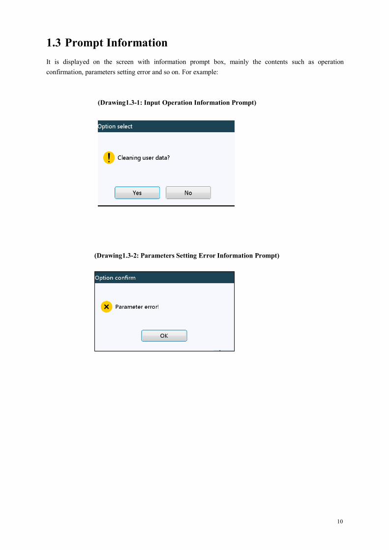
1.3 Prompt InformationIt is displayed on the screen with information prompt box, mainly the contents such as operationconfirmation, parameters setting error and so on. For example:
(Drawing1.3-1: Input Operation Information Prompt)
(Drawing1.3-2: Parameters Setting Error Information Prompt)
11
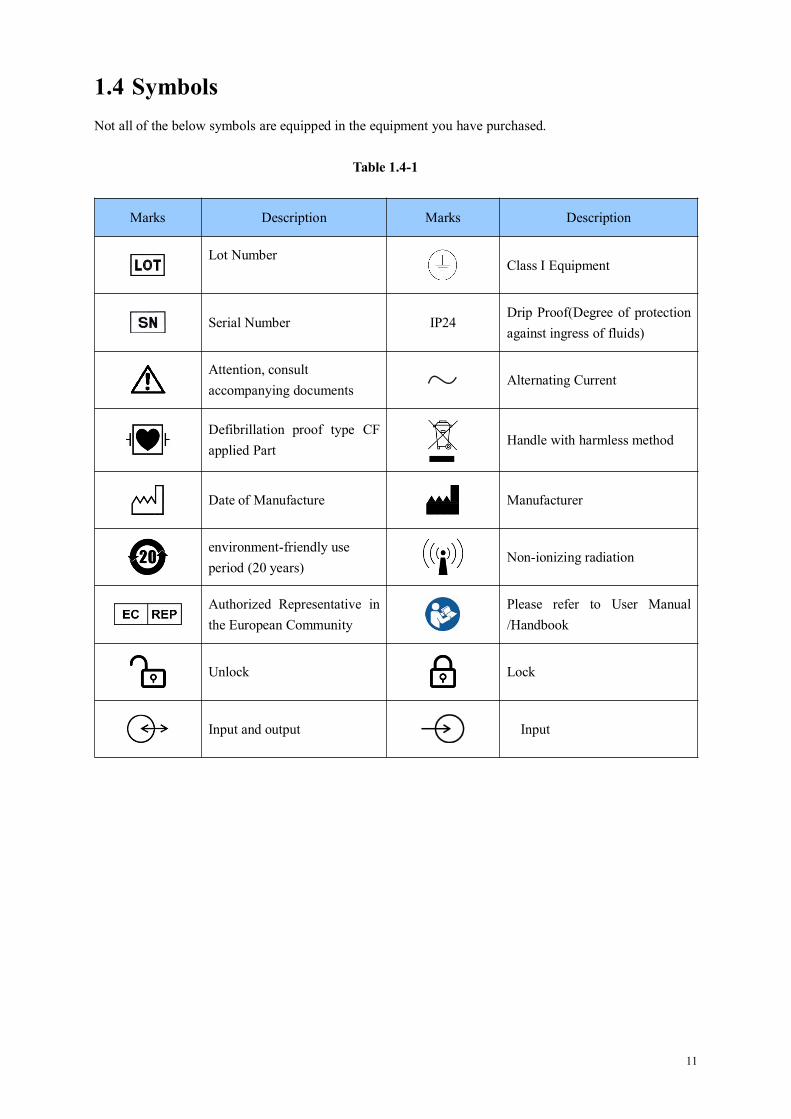
1.4 SymbolsNot all of the below symbols are equipped in the equipment you have purchased.
Table 1.4-1
Marks Description Marks Description
Lot NumberClass I Equipment
Serial Number IP24Drip Proof(Degree of protectionagainst ingress of fluids)
Attention, consultaccompanying documents
Alternating Current
Defibrillation proof type CFapplied Part
Handle with harmless method
Date of Manufacture Manufacturer
environment-friendly useperiod (20 years)
Non-ionizing radiation
Authorized Representative inthe European Community
Please refer to User Manual/Handbook
Unlock Lock
Input and output Input

12
Chapter2 Overview
2.1 Application Scope
2.1.1 Expected PurposeUse with infusion apparatus, do not contact the infusion fluid, adopt by the hospital for intravenousinfusion fluid/drug for patient with adjustable mode.
2.1.2 Expected Working EnvironmentIncluding but not limiting to: hospital ICU (intensive care unit), operating room, neonate intensive careunit(NICU).
2.1.3 Suitable objectAdult, child or neonate.
2.2 ContraindicationsNo
2.3 Working PrincipleThis equipment is a kind of instrument which can drive the pump to extrude the infusion tube for accuratelycontrol of the infusion drops or infusion flow rate with the motor, and is capable of guaranteeing to conveydrug fluid safely in the vein of patient with even rate and accurate dosage.
2.4 Structure and Performance
2.4.1 Structure and PerformanceThe infusion pump mainly composes of the main unit and built-in battery, and can be installed with thedrop sensor. This equipment provides several infusion modes, such as ml/h mode, body weight mode, dripmode, loading dose mode, sequence mode, ramp up/down mode and relay mode. Additionally, it also hasfunctions such as history records, drug library, Anti-bolus, and alarm and so on.
2.4.2 AccessoriesDrop sensor (optional)
13
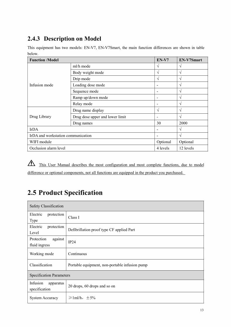
2.4.3 Description on ModelThis equipment has two models: EN-V7, EN-V7Smart, the main function differences are shown in tablebelow.
This User Manual describes the most configuration and most complete functions, due to model
difference or optional components, not all functions are equipped in the product you purchased.
2.5 Product Specification
Safety Classification
Electric protectionType
Class I
Electric protectionLevel
Defibrillation proof type CF applied Part
Protection againstfluid ingress
IP24
Working mode Continuous
Classification Portable equipment, non-portable infusion pump
Specification Parameters
Infusion apparatusspecification
20 drops, 60 drops and so on
System Accuracy ≥1ml/h,±5%
Function /Model EN-V7 EN-V7Smart
Infusion mode
ml/h mode √ √Body weight mode √ √Drip mode √ √Loading dose mode - √Sequence mode - √Ramp up/down mode - √Relay mode - √
Drug LibraryDrug name display √ √Drug dose upper and lower limit - √Drug names 30 2000
IrDA - √IrDA and workstation communication - √WIFI module Optional OptionalOcclusion alarm level 4 levels 12 levels

14
Infusion Rate20-drop specification infusion apparatus: 0.01-1200ml/h60-drop specification infusion apparatus: 0.01-400ml/h
Bolus Rate20-drop specification infusion apparatus: 0.1-1200ml/h60-drop specification infusion apparatus: 0.1-400ml/h
Purge rate 20-drop specification infusion apparatus: 1200ml/h60-drop specification infusion apparatus: 400ml/h
KVO Rate 0.01-5.00ml/h
Micro modesetting range
100-1200ml/h
Minimum flow rateincrement
0.01ml/h
Bolus Volume Minimum 0.1ml, max 50ml
VTBI 0-9999ml, minimum step is 0.01ml
Total VolumeInfused
0.01-9999.99ml, minimum step is 0.01ml
Time Range 1min-99hrs59min
Fuse Type slow fuse 2A 250V
Dimensions 233.5(W)*99(D)*120(H) mm
Weight 1.8kg
Power Supply
AC power supply 100-240V 50/60Hz
Input power 50VA
DC power supply DC 15V
BatterySpecifications
Model: DC 203Specification: 11.1V 2600mAhCharging time: 5h (under OFF state)Working time: ≥9h (after completely charging the new battery, when theenvironment temperature is 25℃ and flow rate is 25ml/h, the constantly workingtime)
Alarm
Alarm signal soundpressure level
When the sound is set at lowest level, alarm signal sound pressure level≥50dB(A)When the sound is set at highest level, alarm signal sound pressure level≤80dB(A)
Alarm information
VTBI near end,VTBI infused, Pressure high, Check upstream, Battery nearly emply, Battery empty, No battery inserted, No power supply, Reminder alarm, Standby time expired, KVO finished, Drop sensor connection, Drop error, Air bubble,Door Open
Environment
15
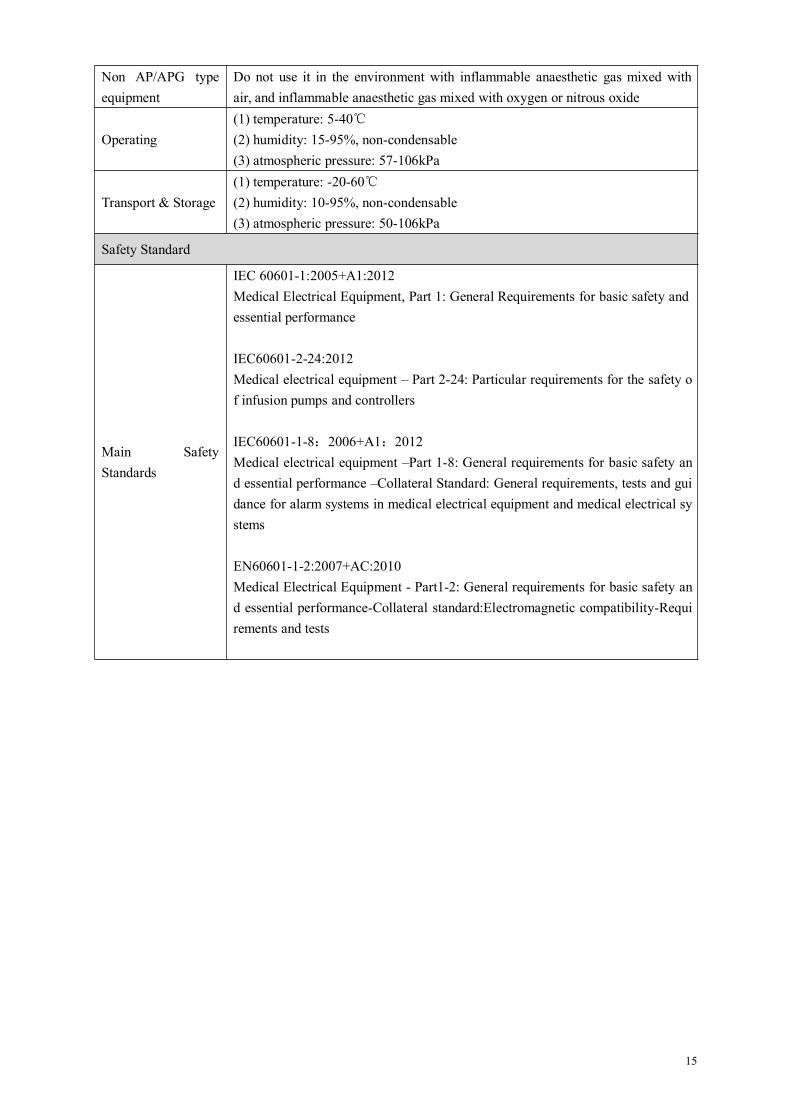
Non AP/APG typeequipment
Do not use it in the environment with inflammable anaesthetic gas mixed withair, and inflammable anaesthetic gas mixed with oxygen or nitrous oxide
Operating(1) temperature: 5-40℃(2) humidity: 15-95%, non-condensable(3) atmospheric pressure: 57-106kPa
Transport & Storage(1) temperature: -20-60℃(2) humidity: 10-95%, non-condensable(3) atmospheric pressure: 50-106kPa
Safety Standard
Main SafetyStandards
IEC 60601-1:2005+A1:2012Medical Electrical Equipment, Part 1: General Requirements for basic safety andessential performance
IEC60601-2-24:2012Medical electrical equipment – Part 2-24: Particular requirements for the safety of infusion pumps and controllers
IEC60601-1-8:2006+A1:2012Medical electrical equipment –Part 1-8: General requirements for basic safety and essential performance –Collateral Standard: General requirements, tests and guidance for alarm systems in medical electrical equipment and medical electrical systems
EN60601-1-2:2007+AC:2010Medical Electrical Equipment - Part1-2: General requirements for basic safety and essential performance-Collateral standard:Electromagnetic compatibility-Requirements and tests

16
Chapter3 Appearance
3.1 Front View
①--- Tubing guide
②--- Pump door
③⑥⑧--- Pressure Plate
④--- Door holder
⑤--- Pressure sensor-UPSTREAM
⑦--- Waterproof cover
⑨--- Pressure sensor-DOWNSTREAM
⑩--- Electric Safety clamp
⑪--- Electric Safety clamp button (for controlling the electric Safety clamp)
⑫--- Air–in-line sensor
⑬--- Wire clamp
Note: It is suggested to replace the waterproof cover once every 2 years. Please refer to this UserManual 11.4 for more detailed information.

17
3.2 Operation Panel
①--- Door open button
②--- Stop button
③--- Start button
④--- Alarm indicator
The alarm indicator indicates the alarm Level with different colors and frequencies, please refer to
Chapter10.1 for detailed information
⑤--- Touch screen
⑥--- Home button
⑦--- Bolus/Purge button
⑧--- On/Off button
Press the Power button to enter into the OFF Setting interface, the user may set OFF, standby (duration) or
cancel.
Hold the Power button till the screen is off, the pump stops.
⑨--- AC indicator
When connecting with AC power supply, AC indicator lights on.

18
3.3 Display ScreenThe display screen interface layout composes of title bar and typical interface.
3.3.1 Title BarTitle bar displays real-time state information and is not touchable, the left upper corner displays the nameof current editing parameter.
Table3.3.1-1: Title Bar Icon
Icon Paraphrase Description
Infusion apparatusindication icon
Infusion apparatus indication icon
Workstation accessicon
It displays only the equipment has accessed the EN-D7 Smartinfusion workstation correctly, please refer to “infusion workstationUser Manual” for details
Lock screenindication icon Unlock state icon is
WIFI indication icon Indicate WIFI connection state.
Pressure indicationicon
Display the pressure change of the current infusion line at real time.When the infusion line pressure changes, the pointer turnsclockwise, when the line pressure reaches or exceeds the setocclusion level default pressure value, it alarms for occlusion.
Battery chargingindication icon
Display the current battery charging state
Battery statusindication icon
The percentage numerical value at the left side of the icon displaysthe remained battery.Since the remained battery may change, it may possibly show thefollowing states:

19
3.3.2 Typical Interface
During infusion preparation and during infusion, the typical interface will display the following interfaces:main interface, working interface, alarm interface, prompt interface, control panel, parameters setting, inputmethod, standby interface and so on.
3.3.2.1Typical Interface Icon Paraphrase
Table3.3.2.1-1
Icon Paraphrase Description
Start Click this icon, start infusion
Stop Click this icon, infusion stop
Bolus/PurgeButton
1. During infusion, it is『Bolus』function, click it to start fast infusion2. Before infusion starting, it is『Purge』function, click it to exhaust airfrom the infusion line
Menus Click this icon, return to the main interface
X/Y Page indication Arabic numerals mean, X is the current page, Y is the total page
Up Click this icon, return to the back page
Down Click this icon to enter into the next page
Return Click this icon, return to the back menu
LeftIn the infusion parameters setting interface, click this icon to turn to theleft page
RightIn the infusion parameters setting interface, click this icon to turn to theright page
Single selectionbox-1
Mean that this parameter is selected
ON Mean this function is ON
OFF Mean this function is OFF.

20
3.3.2.2 Input Method Interface
The input method interface composes of the title bar, input box, editing box.
1) Title bar: display the name of current editing parameter.2) Input box: real-time display the input content.3) Editing box: It composes of the main button area and function button area.
The main button area composes of the numerical value, letters and icons, click it continuously to change thesequence.
The function button area composes of clear button, backspace button,『Cancel』,『OK』and『Shift』.
Icon Paraphrase Description
X Clear button Click it to clear input
< Backspace button Click it to backspace delete
Shift Shift button Click it to switch the capital and lowercase English letters
Cancel Cancel button Click it to cancel editing and exit
OK Enter button Click it to save the input and exit
21
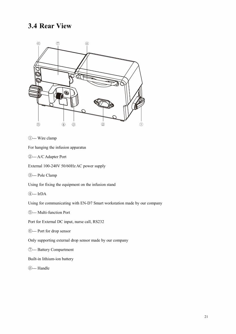
3.4 Rear View
①--- Wire clamp
For hanging the infusion apparatus
②--- A/C Adapter Port
External 100-240V 50/60Hz AC power supply
③--- Pole Clamp
Using for fixing the equipment on the infusion stand
④--- IrDA
Using for communicating with EN-D7 Smart workstation made by our company
⑤--- Multi-function Port
Port for External DC input, nurse call, RS232
⑥--- Port for drop sensor
Only supporting external drop sensor made by our company
⑦--- Battery Compartment
Built-in lithium-ion battery
⑧--- Handle
22
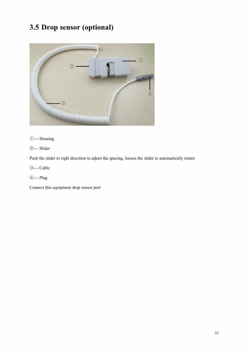
3.5 Drop sensor (optional)
①--- Housing
②--- Slider
Push the slider to right direction to adjust the spacing, loosen the slider to automatically return
③--- Cable
④--- Plug
Connect this equipment drop sensor port

23
Chapter4 Installation
4.1 Unpacking and Checking1) Please check the appearance before unpacking, if the package is damaged, please contact the
transportation company or our after sale service department.
2) Please carefully open the package to avoid damaging the equipment and relevant accessories.
3) After unpacking, please check the objects according to the packaging list, if there’re insufficient ordamaged accessories, please contact our company as soon as possible.
4) Please keep relevant accessories, warranty card and User Manual.
5) Please keep the packing case and packing materials for future transportation or storage.
Warning: Please put the packing materials out of reach of children. Please obey local laws and
regulations or the hospital waste treatment system to handle the packing materials.
4.2 Installation
Warning:
This equipment shall be installed by the designated technicians of our company.
All devices that connect with this equipment must pass the designated IEC standards (for example:IEC60950 information technology equipment safety and IEC60601-1 medical electric device safety)certification, and all devices must be connected according to the valid version of IEC60601-1-1system. The technician who takes charge of connecting to additional devices with the equipmentinterface is responsible for meeting the IEC60601-1-1 standard. Please contact our company if youhave any enquiry.
When connecting this equipment with other electric devices to form the combination with specialfunction, if the combination can’t be confirmed dangerous or not, please contact our company or theelectric expert of hospital to ensure that the necessary safety of all devices in the combination won’t bedestroyed.
This equipment must be used and stored in the environment regulated by our company.
24
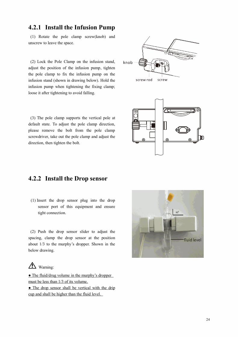
4.2.1 Install the Infusion Pump(1) Rotate the pole clamp screw(knob) and
unscrew to leave the space.
(2) Lock the Pole Clamp on the infusion stand,adjust the position of the infusion pump, tightenthe pole clamp to fix the infusion pump on theinfusion stand (shown in drawing below). Hold theinfusion pump when tightening the fixing clamp;loose it after tightening to avoid falling.
(3) The pole clamp supports the vertical pole atdefault state. To adjust the pole clamp direction,please remove the bolt from the pole clampscrewdriver, take out the pole clamp and adjust thedirection, then tighten the bolt.
4.2.2 Install the Drop sensor
(1) Insert the drop sensor plug into the dropsensor port of this equipment and ensuretight connection.
(2) Push the drop sensor slider to adjust thespacing, clamp the drop sensor at the positionabout 1/3 to the murphy’s dropper. Shown in thebelow drawing.
Warning:
● The fluid/drug volume in the murphy’s droppermust be less than 1/3 of its volume.● The drop sensor shall be vertical with the dripcup and shall be higher than the fluid level.
25
Chapter5 Use Preparation and Cautions
5.1 Use PreparationThe new equipment, or reusing after storing for a period, or reusing after repair, please check it toensure before use:
The equipment appearance is clean and under good condition without crack and leakage.
The moving components are smooth and effective, for example: the pump door can beopened and closed smoothly, the button is effective.
The touch screen can be operated smoothly and effectively.
The power wire is installed tightly and won’t be easily damaged when pulling.
Set and check the system time to ensure that the history records will be correctly recorded.
In case only built-in battery is adopted for supplying power, please charge it to full beforeusing, and ensure that the battery keeps at the effective working conditions.
Carefully read the Warnings, Cautions and Operation Steps listed in this User Manual.
5.2 Operation Cautions
Cautions:
Avoid direct sunlight, high temperature or high humidity.
The equipment shall be put at the position less than 1.2m to the heart of the patient.
The parameters can only be set or changed by the trained and professional personnel.
Avoid the equipment working with fault so as to avoid medical negligence, which may hurtthe health and even life of the patient.
It may possibly drop the infusion accuracy or abnormal work of the equipment if the workingenvironment temperature exceeds the designated range.
The viscosity and specific gravity of infusion fluid will influence the infusion accuracy.

26
Chapter6 Basic Operation
6.1 Operation Flow
¤ Install infusion pump
¤ Turning the power on
¤ Loading Infusion Apparatus
¤ Confirm infusion apparatus brand and specification
¤ Remove air bubble from the infusion line
¤ Select infusion mode
¤ Set Infusion Parameters
¤ Connect the infusion line with the patient
¤ Start infusion
¤Completing the infusion
¤ Remove the infusion apparatus
¤ Power OFF or Standby
6.2 Infusion Operation
6.2.1 Equipment InstallationAfter installing the device on the infusion stand according to Chapter 4.2 of this User Manual,supply AC power. The AC indicator of device lights on, once supplying AC power, the battery willstart charging.
6.2.2 Starting and Self-test1) Press Power button to start the equipment.2) After starting the equipment, it displays the start interface with self-test, the system will
check the motor, sensor, battery, memorizer, CPU communication, alarm indicator.3) After passing self-test, it directly enters into ml/h mode parameters setting interface;
Warning: ● If it fails to pass the self-test, please contact our company and do not continue
using this equipment.

27
6.2.3 Infusion Apparatus Installation
1) Connect the IV line with the infusion bottle.2) Extrude the drip chamber, when the fluid has reached 1/2 position of the drip chamber, open
the roller clamp.3) Fill fluid/drug to the injection needle to remove air, then close the roller clamp.4) Click the door open button to open the door of pump.5) Click the electric safety clamp button to open the safety clamp, install the infusion tube in the
infusion tube slot according to Drawing below, press the middle line of the pump inwards tomake it attach the peristaltic pump. Ensure that items 1-6 shown in Drawing below arecorrectly installed.
6) Click the electric safety clamp button, the electric safety clamp tightens the infusion tube.7) Manually push the pump door to suitable position, the pump door automatically closes.8) Click 『Parameter Set』→ 『Brand』, select infusion apparatus brand.
Warning: ● It is suggested to use the infusion apparatus of the brand attached with this
system.● Please confirm that the infusion apparatus brand and specification displayed in the displayscreen is accordant with the actual one.● Although this equipment supports user-defined infusion apparatus function, in order to ensurethe infusion accuracy, the user is strongly suggested to contact our company, and ask theprofessional technician of our company to set and test the user-defined infusion apparatus.
9) Install Drop sensorPlease install it according to Chapter 4.2.2. After installing, click 『Parameter Set』→ 『Dropsensor』to activate the drop sensor function.
Caution ● The default state of drop sensor function is OFF, this function can be manually
activated by the user when the drop sensor is adopted.

28
6.2.4 Set Infusion ParametersPlease refer to this User Manual7.
6.2.5 Purge Air
In the infusion mode parameters setting interface, click『Purge』 , in the pop-up prompt box,
select『Yes』, after removing air from the infusion line, click『Stop』 .The flow rate from purge is not calculated in the Total Volume Infused.
Cautions
● Purge air from the infusion tube under non infusion state and the IV line is not connected withthe patient.● The purge rate is the max rate of the infusion apparatus, when the single air purge volume ≥5ml,it automatically stops purge.
6.2.6 Start InfusionConnect the infusion tube assembly with the patient, confirm the set parameters, click『Start』button , in the pop-up prompt interface, click『Yes』, start infusion.
6.2.7 Changing the Rate During infusionDuring infusion, click the showed Rate to enter into infusion Parameters Setting interface to setthe flow rate.
Note: ●Only the ml/h mode, drip mode and body weight mode support rate modification
function during infusion.

29
6.2.8 Bolus ApplicationDuring working, Bolus infusion is available, it composes of automatic bolus and manual bolusmodes. The user may select the mode according to the requirement, the infusion volume of bolusis calculated in the total infused volume.
(1) Manual bolus: hold the 【Bolus】 button, the equipment will work according to the defaultmax flow rate of the infusion apparatus system (please refer to this User Manual Chapter 2.5),loosen it to recover the original infusion rate.
(2) Automatic bolus: in the infusion interface, click 『Bolus』 , set any two parameters of thebolus infusion value, rate and time, click 『Bolus start』 . After bolus infusion, the equipmentrecovers to the original infusion rate. To finish bolus infusion in advance, please click 『Stop』.
6.2.9 Infusion CompletionWhen the remaining fluid/drug infusion time in the fluid/drug container reaches the set time forpre-alarm, it will activate VTBI( Volume to be infused) nearly completion alarm. If it is nothandled, the system will keep alarming till finishing infusion, and then transfer to VTBIcompletion alarm. The time for pre-alarm is adjustable, please refer to Chapter 8.1.4 for detailedinformation.
After VTBI completed, it activates VTBI infused alarm, if KVO function is ON, the equipmentautomatically starts KVO function, click 『OK』in the alarm interface to stop KVO and eliminatealarm.
The default working time of the KVO system is 30min, after reaching the time, it will activateKVO completion alarm and stop infusion.
Please refer Chapter 8.1.1 to set KVO rate.
6.2.10Stop InfusionDuring infusion or after infusion, click , infusion stop. The interface display Total VolumeInfused and adjustable parameters.

30
6.2.11Remove the Infusion Apparatus
Disconnect the infusion tube assembly from the patient, click to open the pump door, click the
electric safety clamp button to open the safety clamp, and remove the infusion apparatus.
6.2.12Power OFF or StandbyMethod 1: hold the 【Power】Button till the screen is OFF, the equipment is OFF.Method 2: press the 【Power】Button to enter into OFF interface.
(1) Turn off the equipment: click 『Power off』icon, the equipment is turned OFF.(2) Standby: click『Standby』icon to enter into standby time setting interface, set the standby time.Under standby state, the screen brightness will be lowest, after standby, the screen brightness willbe recovered.(3) Cancel: click 『Cancel』, return to the interface before OFF setting.
Note:
● The equipment has standby function only under the non-working state.● Before turning off the equipment, please confirm that the pump door is closed, otherwise, thepump door can’t be closed after turning off the equipment.
6.2.13Replace Infusion Line/Infusion Container★ Please replace the infusion tube assembly according to the following steps:- Close the flow rate adjuster of the infusion tube assembly, open the infusion pump door, and thenremove the infusion tube assembly.- According to the manual Chapter 6.2.3, prefill and install the new infusion tube assembly.- Operate to restart infusion according to the above infusion steps if needed.
★ Please replace the fluid/drug container according to the following steps:- Close the flow rate adjuster of the infusion tube assembly, open the infusion pump door, andremove the infusion tube assembly.- Remove the fluid/drug container from the infusion tube assembly.- Connect the infusion tube with the new fluid/drug container.- Restart infusion according to the above steps of replacing infusion tube assembly.
Warning: ● The infusion tube will distort if it works for a long period and result inflow rate error, it is suggested to replace the pumping position or infusion tube assembly afterworking for 8h.

31
Chapter7 Set Infusion Parameters
7.1 Introduction to Infusion Parameters Setting(1) The drug information can be displayed in the infusion parameters setting interface only whenthe drug library is under active state.Click『Drug lib』icon in the main interface to set the ON/OFF state of drug library and select drug.Please refer to Chapter9.1 for details.(2) For both the rate set in infusion parameter and the rate calculated by the system, the range isthe system default flow rate of the current working infusion apparatus specification.(3) It doesn’t need to set VTBI (Volume to be infused), which means to complete the fluid/drug inthe infusion container.
7.2 Infusion Parameters Setting RangeInfusion Mode Infusion Parameter Parameter Range
ml /h mode
VTBI 0.01-9999mlRate 20-drop specification infusion apparatus:
0.01-1200ml/h60-drop specification infusion apparatus:0.01-400ml/h
Time 1min-99hrs59min
Body weight mode
Weight(Body weight) 0.1-300kgActi agentia(Drug mass) 0.01-9999.9Agentia unit(Drug unit ) ug, mg, g, U, kU, IU, EU, mmol, mol, kcalVolume(Fluid amount) 0.01-9999mlDose rate 0.01-9999.9Dose unit ug/min, mg/min, g/min, U/min, KU/min,
IU/min, EU/min, mmol/min, mol/min,kcal/min, ug/h, mg/h, g/h, U/h, KU/h, IU/h,EU/h, mmol/h, mol/h, kcal/h, ug/kg/min,mg/kg/min, g/kg/min, U/kg/min, KU/kg/min,IU/kg/min, EU/kg/min, mmol/kg/min,mol/kg/min, kcal/kg/min, ug/kg/h, mg/kg/h,g/kg/h, U/kg/h, KU/kg/h, IU/kg/h, EU/kg/h,mmol/kg/h, mol/kg/h, kcal/kg/h
Drip modeVTBI The same as ml/h modeDrop rate 1-400 dots/min
Loading dosemode
VTBIThe same as ml/h modeMaintain rate
Loading rate
32
Loading time
Ramp up/downmode
VTBI The same as ml/h modeRateRising timeFalling time
Sequence modeRate The same as ml/h modeTime
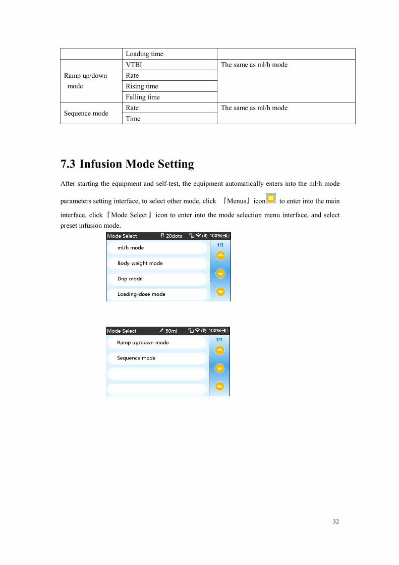
7.3 Infusion Mode SettingAfter starting the equipment and self-test, the equipment automatically enters into the ml/h mode
parameters setting interface, to select other mode, click 『Menus』icon to enter into the main
interface, click『Mode Select』 icon to enter into the mode selection menu interface, and selectpreset infusion mode.

33
7.3.1 ml/h Mode
Under this mode, it allows to set three parameters: Rate, VTBI (Volume to be infused) and Time,set any two of the three parameters, and the system will automatically calculate the thirdparameter, if the VTBI is 0, then the equipment works at the set rate till stop with alarm.
7.3.2 BodyWeight Mode
Under this mode, set the Weight(body weight), Acti agentia(drug mass), Agentia unit(drug unit),Volume(fluid volume), Dose rate, Dose unit, VTBI.The system will automatically calculate the flow rate from the specified dose rate (ug/kg/min,mg/kg/min, ug/kg/h, mg/kg/h,…etc) according to related formula {dose rate × weight}/{Actiagentia(drug mass)/Volume(fluid volume)}, and automatically calculate the time according to(VTBI) /(flow rate).
Exmaple: the dose rate unit(ug/kg/min)D ( / / min) eight(kg) ( ) rate (ml/h)= 60
Acti agentia(mg) 1000ose rate ug kg W Volume mlflow
Exmaple: the dose rate unit(mg/kg/h)D ( / / ) eight(kg) ( ) rate (ml/h)=
Acti agentia(mg)ose rate mg kg h W Volume mlflow

34
7.3.3 Drip mode
Under this mode, set the VTBI and drop rate, and the system will automatically calculate theinfusion flow rate and time.
Note: ● The flow rate under drip mode is calculated according to the specification of the
current infusion apparatus, before adopting the drip mode, please confirm that the specification ofthe current infusion apparatus is accordant with the specification displayed in the interface title bardisplay, if it is not accordant, please contact the equipment maintenance technician to modify,otherwise, it may cause serious deviation of flow rate.
7.3.4 Loading dose mode
The Loading dose mode means to infusion with the Loading flow rate according to the Loadingtime, after reaching the Loading time, it works at the Maintain rate till complete theVTBI( Volume to be infused).Loading dose VTBI =Loading rate ×Loading timeMaintain time = (VTBI -Loading VTBI) /Maintain rate
Under this mode, set the VTBI, Maintain rate, Loading rate, Loading time, systemautomatically calculate Loading dose VTBI and Maintain time.
Note: ● VTBI must be greater than the Loading dose VTBI otherwise, when setting exceeds
the limit, the excess part can’t be set.
35
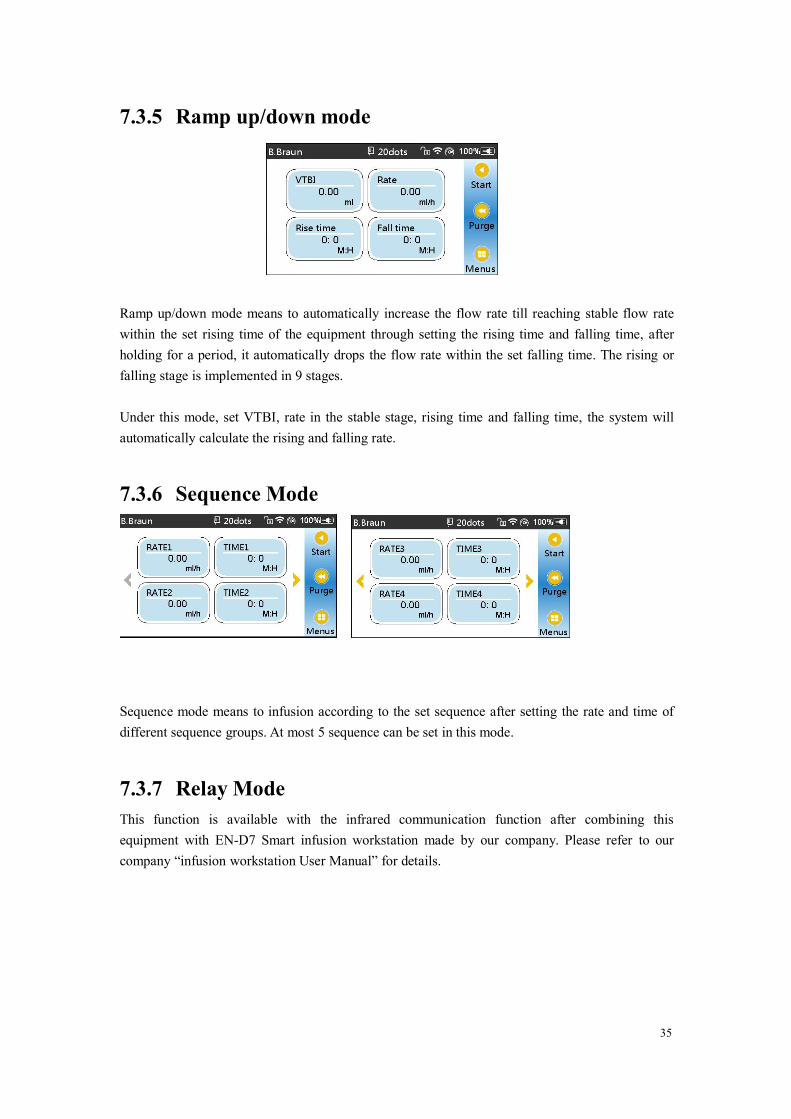
7.3.5 Ramp up/down mode
Ramp up/down mode means to automatically increase the flow rate till reaching stable flow ratewithin the set rising time of the equipment through setting the rising time and falling time, afterholding for a period, it automatically drops the flow rate within the set falling time. The rising orfalling stage is implemented in 9 stages.
Under this mode, set VTBI, rate in the stable stage, rising time and falling time, the system willautomatically calculate the rising and falling rate.
7.3.6 Sequence Mode
Sequence mode means to infusion according to the set sequence after setting the rate and time ofdifferent sequence groups. At most 5 sequence can be set in this mode.
7.3.7 Relay ModeThis function is available with the infrared communication function after combining thisequipment with EN-D7 Smart infusion workstation made by our company. Please refer to ourcompany “infusion workstation User Manual” for details.
36
Chapter8 System Setting
8.1 Parameter SetClick『Parameter Set』icon in the main interface to enter into parameters setting interface.
8.1.1 KVO RateClick『KVO rate』, input the numerical value, after confirming, click『OK』.Please refer to Chapter 2.5 for the adjustable KVO range.
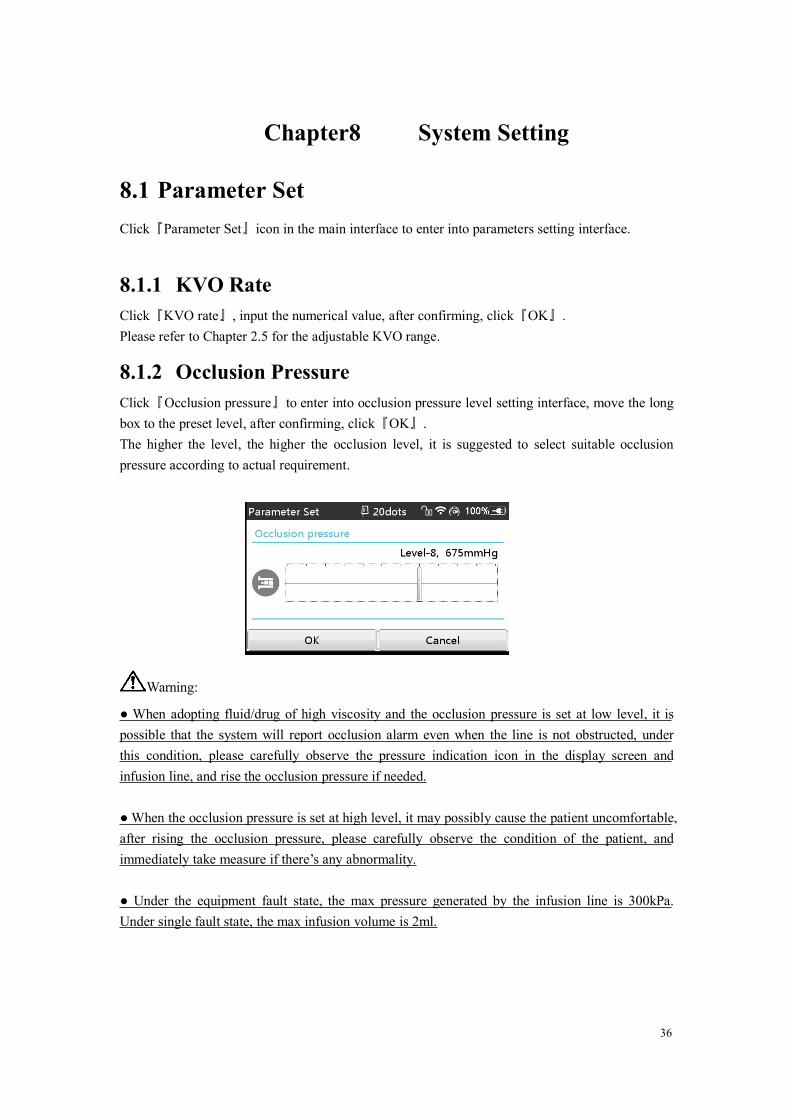
8.1.2 Occlusion PressureClick『Occlusion pressure』to enter into occlusion pressure level setting interface, move the longbox to the preset level, after confirming, click『OK』.The higher the level, the higher the occlusion level, it is suggested to select suitable occlusionpressure according to actual requirement.
Warning:
● When adopting fluid/drug of high viscosity and the occlusion pressure is set at low level, it ispossible that the system will report occlusion alarm even when the line is not obstructed, underthis condition, please carefully observe the pressure indication icon in the display screen andinfusion line, and rise the occlusion pressure if needed.
● When the occlusion pressure is set at high level, it may possibly cause the patient uncomfortable,after rising the occlusion pressure, please carefully observe the condition of the patient, andimmediately take measure if there’s any abnormality.
● Under the equipment fault state, the max pressure generated by the infusion line is 300kPa.Under single fault state, the max infusion volume is 2ml.

37
(Table: Relation of Occlusion level and Pressure)
Applicable Model: EN-V7 Occlusion Pressure Level: 4 levelsLevel Pressure Intensity
(mmHg)Pressure Intensity
(Kpa)Pressure Intensity
(bar)Pressure Intensity
(psi)1 225 30 0.3 4.352 450 60 0.6 8.73 675 90 0.9 13.054 900 120 1.2 17.4
Applicable Model: EN-V7Smart Occlusion Pressure Level: 12 levelsLevel Pressure Intensity
(mmHg)Pressure Intensity
(Kpa)Pressure Intensity
(bar)Pressure Intensity
(psi)1 150 20 0.2 2.902 225 30 0.3 4.353 300 40 0.4 5.84 375 50 0.5 7.255 450 60 0.6 8.76 525 70 0.7 10.157 600 80 0.8 11.68 675 90 0.9 13.059 750 100 1 14.5
10 825 110 1.1 15.9511 900 120 1.2 17.412 975 130 1.3 18.85
8.1.3 Bubbles SizeClick『Bubbles size』to enter into air bubble size setting interface, move the long box to the presetlevel, confirm and then click『OK』.The air bubble detector has 7 levels, when the volume of single air bubble or the total air bubbleswithin 15min in the line reach the preset air bubble testing alarm threshold value, it will activateair bubble alarm. The air bubble testing sensitivity is 20ul. It is suggested to select suitable levelaccording to the actual requirement.
Air Bubble detector level Alarm Threshold ValueLevel 1 50ulLevel 2 100ulLevel 3 200ulLevel 4 300ulLevel 5 450ulLevel 6 600ulLevel 7 800ul
38
8.1.4 VTBI Infused Pre-AlarmTime for pre-alarm refers to the time of activating nearing completion alarm when the fluid/druginfused volume is nearly reaching the preset value.
Click『VTBI infused pre-alarm』 to enter into the time for pre-alarm setting interface, click thepreset time option, then the corresponding icon of this option changes into .
The adjustable range of time for pre-alarm is: 2min, 5min, 10min, 15min, 20min, 30min.
8.1.5 ReminderAlarmClick『Reminder alarm』to enter into the time for reminder alarm setting interface, click the presettime option, then the corresponding icon of this option changes into . The adjustable range oftime for Reminder alarm is: 2min, 5min, 10min, 15min, 20min, 30min.
Reminder alarm means that the system will activate “Reminder alarm” if no button is operatedwithin the preset time for “Reminder alarm” when the equipment is under no infusion no alarmstate.
8.1.6 Weight UnitClick『Weight unit』to enter into the body weight unit setting interface, click preset body weightunit option, then the corresponding icon of this option changes into .
8.1.7 Setting Pressure UnitClick『Pressure unit』to enter into pressure unit select setting interface, four units are available:mmHg, kPa, bar, PSI, click the preset unit option.
Note: ● Please carefully confirm when changing the current pressure unit.
Unit Mark Unit ConversionkPa 1 kPa=7.5mmHg=0.145psi=0.01barPSI 1psi=51.724mmHg=6.897kpa=0.069barBar 1bar=750mmHg=14.5psi=100kPa
8.1.8 Setting Micro ModeClick『Micro mode』to enter into micro mode setting interface. ON/OFF is optional in this functionOptional. Under the ON mode, set the rate limit, then the infusion rate under any infusion mode isnot allowed to exceed this limit.
39
8.1.9 Drop SensorClick『Drop sensor』to set ON or OFF.The “Drop error “ alarm function is only available only when the drop sensor is installed.
Note: ● The default state for drop sensor function system is OFF, it can be manually turned
on by the user when the drop sensor should be adopted. If the function is ON when the drop sensoris not installed, then the system will report “drop sensor connection” alarm.
8.1.10BrandFor the built-in infusion apparatus brand of the system, after installing the infusion apparatus,click 『Brand』to enter into the infusion apparatus brand selecting interface, and click the presetbrand option.The system built-in infusion apparatus brand: Jierui, GSYJX (Authorization) No. [2014]3660426.
● The infusion apparatus of different brand may possible cause flow rate deviation, when
use, please confirm if the displayed information in the interface is accordant with the actualworking infusion apparatus.
8.1.11Reset Total Volume
Click『Reset total volume』 , the interface displays the operation confirming prompt box, click『Yes』to confirm reset, otherwise, please click『No』
8.2 GeneralIn the main interface, click『General』to enter into the equipment setting interface.
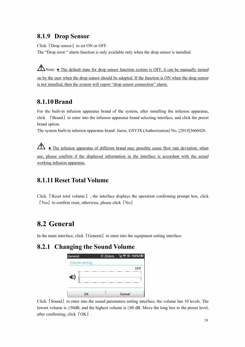
8.2.1 Changing the Sound Volume
Click『Sound』to enter into the sound parameters setting interface, the volume has 10 levels. Thelowest volume is ≥50dB, and the highest volume is ≤80 dB. Move the long box to the preset level,after confirming, click『OK』.
40
8.2.2 Setting Date and TimeClick『Date &Time』to enter into the date and time setting interface. It allows to set the date, timeand format in this interface.
When setting date and time, directly input the numerical value in the input method interface. Forexample, to preset one date “2015-08-31”, input “20150831”; to preset the time “13: 34”, input“1334”.
The time is displayed in 24h format or 12h format, the date is displayed in British type, Americantype or Chinese type, please set according to the requirement.
8.2.3 Screen LockClick『Screen lock』to enter into automatic lock screen setting interface, select ON or OFF.
Automatic lock screen time can be set at 15s, 30s, 1min, 2min, 5min, 10minor 30min and so on,which means that the equipment will automatically lock the screen if it is not touched or thebutton is pressed within corresponding time after starting.
Unlock: directly click『Cancel』in the lock screen interface.
Note: ● The equipment will automatically unlock if there’s high Level alarm.
8.2.4 BrightnessClick 『Brightness』to enter into display brightness setting interface. The brightness has 10 levels.The equipment has the function of automatic brightness adjustment if external power supply isunavailable. When there is no external power supply, and the power is supplied by battery, if it isnot operated within 3min, the system will automatically adjust the brightness to the lowest level,when it is touched or button is clicked by user or when there’s alarm, it will automatically recoverthe brightness.
8.2.5 Night ModeClick『Night mode』to enter into night mode switch setting interface to set the start and end time ofthe night mode and the night brightness, at night, the system automatically adjusts the brightnessto the User defined value.
8.2.6 Touch Screen CalibrationOperate according to the prompt information displayed in the interface to calibrate the touchscreen.

41
8.2.7 Nurse CallClick『Nurse call』to select function ON and OFF.
Note: ● The nurse call function must be used with special cable.
● The user shall not only depend on the nurse call function as the main alarm notice mode, andshall identify according to the equipment alarm and the patient state.
8.3 NetWorkThis equipment supports wireless or wire interconnection, when it is equipped with wireless
module and connects with the internet through WIFI, the equipment screen displays icon.
Click『NetWork』in main interface to set the response.
Note: ● This function shall be set by the professional equipment maintenance technician.
● After activating the interconnection function, the equipment can periodically transmit theequipment data to outside, and the data is only for displaying and doesn’t provide any suggestionon therapy.
8.3.1 Connection ModeThe connection mode supports WLAN and serial port modes, please select according to the actualrequirement.
8.3.2 WLANWhen WIFI function is in use, turn on the WLAN switch of the equipment, set the name andpassword of access point, and configure the TCP/IP parameters.
Note: ● The wireless access must be set by the professional technician recognized by our
company.● The transmitted data of this equipment doesn’t provide any suggestion on therapy, and this datashall not be used for calculating the therapeutic schedule.● When the data is adopted by the third party’s equipment or software, it is only for displaying,and shall not be used for alarming or calculating.

42
8.4 System InformationClick『System Info』in the main interface to enter into system information setting interface.
8.4.1 Setting LanguageThis equipment supports simplified Chinese and English.
8.4.2 Factory Data ResetClick『Factory data reset』to clear the User defined option, and this function is open to the user.
8.4.3 Serial Number(SN)Check the serial number of the equipment, and user can’t modify the serial number.
8.4.4 MaintenanceThis function is not open to general user. It is suggested to contact our company or local dealer,and customize and calibrate it by professional technician, otherwise, it can’t guarantee the infusionaccuracy.
8.4.5 VersionCheck the software version in this interface.

43
Chapter9 Other Functions
9.1 Drug libraryClick 『DrugLib』in the main interface to enter into drug library setting interface.
9.1.1 Introduction to Drug library
(1) EN-V7Smart supports over 2000 drug names, which can be imported with external tool, andhas the functions such as upper and lower limit, concentration, color and so on.
Select drug and then import the drug parameters, the user may change the parameters includingthe concentration and dosage rate, but the parameters won’t be saved.
When working, the background color of the drug name shall be accordant with the set color.
(2) EN-V7 supports 30 drug names, and allows to edit the drug name, save the names afterturning off the machine, but the upper and lower limit function is unavailable.
9.1.2 Setting Drug libraryClick the drug name with preset. The selected drug will be displayed in the infusion modeparameter.
Select this function ON/OFF.
9.2 Patient Information SystemClick『Patient Info』in the main interface to enter into setting interface.
9.2.1 Patient InformationClick『Patient』to enter into the patient information setting interface and set the hospitalizationnumber, name, gender, age, body weight, height and BMI.
BMI index (means body mass index, also named as body weight) is the number produced withheight (m) after divided by body weight (kg), and is the common standard in the world to measurethe obesity degree and health conditions.
9.2.2 Doctor’s OrderClick『Doctor’s order』to enter into the patient information setting interface and set the medicaladvice ID, medical advice information, executing time and state.

44
9.3 Therapy Record
Click『Therapy Records』in the main interface to enter into medical records query interface.(1) This interface displays the latest 20 medical records, user may directly select it as the currentinfusion plan, after confirming the parameters, it starts infusion.
(2) The system can save 20 medical records at most, when it is full, the new records will cover theold records by turn.
9.4 HistoryClick『History』in the main interface to enter into history records query interface. The equipmentsupports to save over 5000 history records, and can display the event name, event date and time.When it is full, the new records will cover the old records by turn.
9.5 Anti-bolusWhen the line occlusion activates occlusion alarm, the system will automatically drop the linepressure to avoid additional impact bolus to the patient after contacting the occlusion.
9.6 Electronic Memory FunctionAfter turning off the equipment, the electronic memory function can be saved for 5 years at least.When the power failure time is ≤30s, the alarm setting before power failure will be automaticallyrecovered.
9.7 Data ExportLog on the PC tool to connect this equipment with PC;After the equipment has achieved communication with PC, the PC can automatically read the datain this equipment;Create the history record folder in the PC to export the data to the folder.
Note: ● Please do not export data when the equipment is working.
Chapter10 Alarm Prompt and

45
Troubleshooting
10.1 Introduction to Alarm LevelDuring infusion preparation and infusion, this equipment will alarm when reaching or exceedingthe set alarm threshold value and prompt with sound, light and text. According to the importanceof alarm information as well as the emergency and safety, the alarm is divided into three levels:high, middle and low. Please refer to table below for details:
Alarm Level Sound Signal Interval Light color /flash frequencyHigh alarm 10s Red indicator flashes /2.0±0.6HzMiddle alarm 15s Yellow indicator flashes / 0.6±0.2HzLow alarm Once, not repeated Yellow indicator lights on
If there’s alarm, the system will display the alarm interface. Click『OK』to exit the alarm interface.
(Drawing10.1-1: Alarm Interface)
Click『Mute』to mute, if alarm is not eliminated, the alarm sound will be sent out 2min later.
Warning ● Some alarm threshold values of this equipment can be set by the user, for
example: occlusion pressure, air bubble alarm, reminder alarm, VTBI infused pre-alarm, alarmsound volume and so on, the user shall confirm the parameters when set the alarm threshold value,otherwise, it may possibly influence the alarm function or infusion safety.

46
10.2 Multilevel Alarm RulesWhen there’re several alarms, the system will alarm according to the following rules:
Table10.2-1
Multilevel Alarm RulesSeveral alarms of differentlevels generatesimultaneously
Display the alarms of highest level with sound, light and text,report middle alarm after eliminating all alarms of highest level
Several alarms of same levelgenerate simultaneously
Alarm circularly by turns, the time interval is 1s
10.3 Alarm Treatment
Warning ● When there’s alarm, please check the conditions of the patient, remove the
reason of alarm and then continue working.
Please refer to Appendix C for the alarm solution.
10.4 Fault Analysis and SolutionWhen there’s fault, the infusion pump screen will display the fault alarm information, this item isthe alarm of high level. Please eliminate the fault alarm according to the prompt. If it can’t beeliminated, please stop the equipment, contact our company to repair and test the equipment, donot put it into operation before the equipment has passed the inspection, otherwise, it may possiblycause unpredictable harm if it works with fault.
If the equipment is on fire/burns for unknown reason, or has other abnormal conditions, the usershall immediately cut off power supply and contact our customer service department.
Under single fault state, the max infusion volume is 2ml.

47
Chapter11 Maintenance
11.1 Cleaning, disinfecting and sterilizing
Warning
● Please cut off power supply and unplug the DC /AC power wire before cleaning the equipment.● During cleaning and disinfecting, please keep the equipment horizontal and upwards to protectthe equipment and accessories from fluid.
11.1.1Cleaning(1) The daily maintenance is mainly to clean the housing and pump body. It is inevitable that
fluid/drug may flow in the equipment during infusion. Some fluid drug may corrode thepump and cause working fault. After infusion, please timely clean the equipment, wipe itwith moist and clean soft fabric, and then naturally dry it.
(2) When cleaning the equipment interface, please wipe it with dry and soft fabric, confirm theinterface is dry before using.
(3) Please do not soak the equipment in water. Although this equipment has certain waterprooffunction, when fluid splashes on the equipment, please check if it works normally, performinsulation and electric leakage test if needed.
11.1.2Disinfecting(1) Disinfecting may possibly cause harm of certain degree to the equipment, it is suggested to
disinfect the equipment if it is needed.
Please disinfect the equipment with common disinfecting agent such as 50% sodium hypochlorite,10% hypochlorous acid, 3% hydrogen peroxide, aerodesin 2000 (mainly containing alcoholdisinfecting solution), cidex 2% glutaraldehyde + activating agent, virex disinfecting based onorganic ammonium chloride, betadine sterilizing agent (povidone iodine solution), 70% ethanol,70% isopropyl alcohol, 10% physiological saline and so on. Please follow the instructions of thedisinfecting agent.
(2) After disinfecting, wet the soft fabric with warm water, dry the fabric and then wipe theequipment with it.
(3) Do not sterilize the equipment with high pressure steam sterilizer, do not dry the equipmentwith dryer or similar product.
48
Warning: ● Please do not adopt Cidex OPA orthophthalaldehyde, methyl ethyl ketone or
similar solvent, otherwise, it may corrode the equipment.
11.2 Periodical maintenance
Notes: ● The medical mechanism shall set up complete maintenance plan, otherwise, it may
possibly cause the equipment malfunction or fault, and may possibly hurt the physical safety.
● In order to ensure the safe use and prolong the service life of the equipment, it is suggested toperiodically maintain and check it once every 6 months. Some items shall be maintained by theuser, and some items shall be maintained by the dealer of the equipment.
● Please timely contact our company if the equipment is found defective.
11.2.1Check the Appearance(1) The appearance of the equipment shall be clean and under good condition without crack and
water leakage.(2) The buttons are flexible and effective without invalid phenomenon; the sensitivity of the
touch screen is normal,(3) The infusion pump door can be smoothly opened and closed, the electric safety clamp switch
is under good condition.(4) The power wire is under good condition and installed tightly.(5) After connecting with external power supply, check if the AC indicator of the equipment AC
indicator lights on normally.(6) Adopt the accessories designated by our company.(7) The environment meets the requirements.
11.2.2 Performance Check(1) Self-test and normal infusion function.(2) Alarm function normal(3) Battery performance.
11.2.3 Maintenance PlanThe following check/maintenance items must be performed by the professional technicianrecognized by our company. If the following maintenances are necessary, please contact ourcompany. Please clean and disinfect the equipment before testing or maintaining.

49
Maintenance Items Cycle
Safety check according to IEC60601-1Once every 2 years, please check afterreplacing the printed circuit board assembly orthe equipment is dropped or knocked.
Preventive system maintenance items (pressurecalibrate, sensor calibrate, pump)
Once every 2 years, when the occlusion alarm,air bubble alarm, or infusion accuracy is doubtto be abnormal
Brand of user-defined infusion apparatus,infusion accuracy calibration
Using the equipment for the first time, infusionapparatus brand using for the first time, reusingthe equipment after stopping for a very longperiod.
11.3 Calibration
In the『System Info』menu, enter into『Maintenance』interface, click『Brand』to enter into brandsetting interface, create the consumables brand, delete and calibrate the brand.
Warning: ● It is suggested to contact our company or local dealer, and customize and
calibrate it by professional technician, otherwise, it can’t guarantee the infusion accuracy.
Note: ● The built-in brand of the system shall not be deleted.
(1)NewIf the actual using infusion apparatus brand is not listed in the system built-in brand, please createthe infusion apparatus brand in this interface.Input the name and specification of infusion apparatus brand.(2) DeleteEnter into『Delete』interface, click it to delete user-defined infusion apparatus brand.(3) CalibratePlease calibrate the infusion apparatus when using the built-in brand infusion apparatus for thefirst time, or the first user-defined infusion apparatus brand, or after periodical maintenance.Please prepare the following materials before calibrating:One new and unused infusion apparatus, 20ml measuring cup or 20ml injector.
Calibrating Steps:
1) Install the infusion apparatus according to the requirements and remove the air bubbles;
2) Put the needle into the measuring cup for collecting fluid;
3) Start calibrating according to the interface prompt, the equipment starts infusion;
4) After working for 10min, the equipment will automatically stop, read the fluid amount in the

50
measuring cup or calculating the fluid volume by weighing;
5) Input the reading in the interface and complete calibration;
6) After exiting the calibration interface, select the calibrated brand as the current brand, and thenverify the infusion accuracy with 25ml/h and 150ml/h flow rate respectively.
11.4 Repair
11.4.1Normal Repair ProcessPlease contact the our company to repair if there’s any fault, do not disassemble and repair theequipment. After repair, please perform overall test for the equipment. Our company may providethe circuit diagram and components list to the authorized repair technician if needed.
11.4.2Maintenance for Long Term StoreIf the equipment won’t be used for a long period, please take out the battery, and pack it with theequipment in the package, and store it in the shade, cool and dry place without direct sunlight.The following operations are necessary for using it again:
1. Verify the flow rate accuracy to avoid unconformity between the infusion apparatus parametersin the equipment and the actual parameters after it hasn’t be used for a long period or caused byother reasons, otherwise, it may cause infusion error, influence the therapeutic effects and evencause medical negligence.
2. Perform air bubble and occlusion alarm test.
3. Test the battery discharging and charging duration to confirm that the battery is also usable.
11.5 Equipment Components/Accessories
Warning: ● Only the components and accessories designated by our company shall be
adopted, otherwise, it may possibly damage the equipment or drop the equipment performance.
During the normal service life of the equipment, the battery and waterproof cover are consumables,it is suggested to replace them once every 2 years, please contact the dealer or our company toreplace them.

51
Variety Name CodeAccessories Drop sensor 63-000017-00EquipmentComponents
Waterproof cover 24-000021-02Battery 09-000004-00Pole clamp 63-000006-00Power wire 13-200001-00
11.6 Production DatePlease refer to the label of the product
11.7 Recycling
The normal service life of this equipment is 5 years, and depends on the use frequency andmaintenance. The equipment must be rejected after reaching the service life, please contact themanufacturer or the dealer to get more detailed information.
1. The obsolete equipment may be returned to the original dealer or manufacturer.2. The used lithium-ion polymer battery has the same treatment method, or according to theapplicable laws and regulations.3. Please handle according to the equipment rejecting flow of your medical mechanism.
52
Chapter12 Battery
This equipment is equipped with charging lithium-ion polymer battery to ensure the normalinfusion when the equipment is moved or the external power supply is cut off.
When connecting external power supply, no matter the equipment is started or not, it can chargethe battery. When charging, the equipment screen displays the battery charging indication icon
. In case only built-in battery is adopted for supplying power, and when the remained batteryis less than 20%, please connect the equipment with external power supply to charge the battery.
Warning: ● Only the battery designated by our company shall be adopted.
12.1 Check the Battery PerformanceThe performance of the built-in battery may drop according to the using duration, it is suggestedto check the battery once a month.
(1) Disconnect the equipment from the patient, and stop all infusions.(2) Supply public power to the equipment to charge the battery for 5h at least.(3) Supply power for the infusion pump only with battery, infusion at the rate of 25ml/h, test the
time till the battery runs down and the equipment is turned off.- If the infusion time exceeds 7h, the battery keeps at good state.- If the infusion time exceeds 5h but less than 7h, the battery starts deterioration, but it can be usedtemporarily.- If the infusion time is less than 5h, the battery is reaching the service life, please replace thebattery.
12.2 Replaced the Battery
It is better to replace the battery once every 2 years, it is suggested to replace the battery by thedealer or manufacturer.The steps of replacing battery are shown as below:⑴ Cut off the power supply of the equipment, disconnect the power wire. Open the cover of
battery chamber and take out the battery.⑵ Push the new battery into the battery chamber, and insert in the battery fastener.⑶ After replacing the battery, install the battery cover, and check the battery.
Warning: ● When replace the battery, please do not touch the 12V DC plug inside of the
batter Chamber.
53
Chapter13 After Sale ServiceThis product enjoys 1-year free warranty after purchase. The warranty period is from theinstallation date listed on the “Warranty Card”. The “Warranty Card” is the only voucher forcalculating the warranty period, in order to maintain your benefit, please carefully fill into andkeep the “Warranty Card”, and hand over the copy for the company to the installation technician.
The damages of the equipment caused by the following shall not enjoy free warranty service.
1. Fault caused by incorrect operation, unauthorized refitting or repair.
2. The damages caused by incorrect operation during the transportation process after purchase.
3. The fault and damages caused by fire, salt injury, toxic gas, earthquake, windstorm, flood,abnormal voltage and other natural disasters.
For the damages or faults mentioned above, our company provides repair services but chargeableaccording to the repair cost.
Name of Registrant /Manufacturer: Shenzhen Enmind Technology Co., Ltd.
Address of Registrant/ Manufacturer: Rm. 201, Block A, No. 1, 1st Qianwan Rd., QianhaiShenzhen-Hong Kong Cooperation Zone, Shenzhen
Address of Registrant/ Manufacturer: Building 5, Block A, Defengsheng Mansion, No. 41,Dabao Rd., Baoan District, Shenzhen
Production License Code:
Product Technical Requirements/Registration Certificate Code:
Phone Number of Registrant /Manufacturer: 0755-22276344
After Sale Service Unit: Customer Service Department of Shenzhen Enmind Technology Co.,Ltd.
Address of After Sale Service: 5/F, Block A, Defengsheng Building, o. 41, Dabao Rd., 23 Bao’anDistrict, Shenzhen
Contact Information of After Sale Service: 0755-22276344

54
Chapter14 Appendix
Appendix A Start Up Graphs and Trumpet Curves
Appendix A.1 Start-up GraphsBrand and specification of infusion apparatus: Jierui(20 drops)Flow Rate: 1ml/hMeasurement Interval: ∆ t = 0.5minMeasurement duration: T = 2h
Graph 1 Start-up graph: Flow rate 1 (ml/h) against time (min) plotted from data gatheredduring the first 2 h of the test period
Brand and specification of infusion apparatus: Jierui (20 drops)Flow Rate: 25ml/hMeasurement Interval: ∆ t = 0.5minMeasurement duration: T = 2h
Graph 2 Start-up graph: Flow rate 25 (ml/h)against time (min) plotted from data gatheredduring the first 2 h of the test period
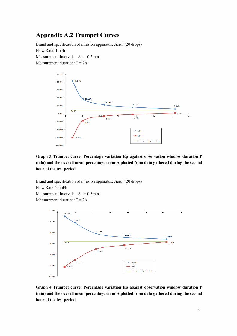
55
Appendix A.2 Trumpet CurvesBrand and specification of infusion apparatus: Jierui (20 drops)Flow Rate: 1ml/hMeasurement Interval: ∆ t = 0.5minMeasurement duration: T = 2h
Graph 3 Trumpet curve: Percentage variation Ep against observation window duration P(min) and the overall mean percentage errorA plotted from data gathered during the secondhour of the test period
Brand and specification of infusion apparatus: Jierui (20 drops)Flow Rate: 25ml/hMeasurement Interval: ∆ t = 0.5minMeasurement duration: T = 2h
Graph 4 Trumpet curve: Percentage variation Ep against observation window duration P(min) and the overall mean percentage errorA plotted from data gathered during the secondhour of the test period

56
Appendix B Occlusion Response Property
EN-V7Smart occlusion time and bolus relation:
EN-V7 occlusion time and bolus relation:
Notes: The alarm pressure intensity error for EN-V7Smart is ±15% or ±100mmHg, the highervalue shall be taken;The alarm pressure intensity error for EN-V7 is ±20% or ±150mmHg, the higher value shall betaken.
Notes: ● Conditions for testing above data: infusion apparatus brand Jierui.
● The occlusion alarm pressure, alarm delay time and bolus are influenced by thetest conditions.
● The above data is the typical value under the test conditions, please see the testdata of the product for the actual data, the data may be different if the testconditions are different
Flow Rate(ml/h)
Occlusion Pressure(mmHg)
Time to occlusion alarm(min)Max bolus
(ml)
1Low 150 0h 6min 40sec 0.008High 975 0h 50min 27sec 0.143
25Low 150 0h 0min 38sec 0.007High 975 0h 1min 40sec 0.131
Flow Rate(ml/h)
Occlusion Pressure(mmHg)
Time to occlusion Alarm(min)Max bolus
(ml)
1Low 225 0h 7min 19sec 0.012High 900 0h 46min 45sec 0.133
25Low 225 0h 0min 36sec 0.008High 900 0h 1min 29sec 0.126

57
Appendix C Alarm and SolutionAlarm Type Alarm
LevelReason Solution
VTBI nearend
Middle
During infusion, the remainingtime of reaches or is lessthan the set nearingcompletion time
This alarm can’t be eliminated,and waits till infusion completes
VTBIinfused
HighThe preset value infusionCompletion
Press 【 Stop 】 button to stopalarm
Pressure high High
1. Line occlusion duringinfusion
Manually remove the reason ofocclusion, Press【Start】 buttonto continue infusion
2. Fluid/drug in the actualinfusion line has highviscosity, but the systemocclusion level is set too low
Rise the alarm Level, Press【 Start 】 button to continueinfusion
3. The pressure sensor isdamaged
Please contact the dealer ormanufacturer for repair
Checkupstream
High
The upper part of the line isobstructed during infusion, andin turn drops the line pressureintensity
Check if the rate regulatingadjuster or fluid stopping deviceis opened at the upper part of theline, Press【Stop】button to stopalarm
Batterynearly empty
Middle
1. When power is suppliedonly with the built-in battery,under low battery, the alarmduration is >30min
The alarm automaticallyeliminates after connecting theexternal power supply.
2. Battery ageing or theequipment charging circuit isfault.
Please contact the dealer ormanufacturer for repair.
Batteryempty
High
When power is supplied by thebuilt-in battery only, under lowbattery, the alarm durationis >30min
Immediately connect withexternal power supply.
2. Battery ageing or theequipment charging circuit isfault.
Please contact the dealer ormanufacturer for repair.

58
Alarm Type AlarmLevel
Reason Solution
No batteryinserted
Middle Battery is removedKeep connecting with externalpower supply, reinstall thebattery
No powersupply
Low
Under ON state, AC powersupply is adopted, but the ACpower wire is dropped duringthe process
The alarm automaticallyeliminates after connecting theexternal power supply.
Reminderalarm
Middle
After installing infusion tube ,under non-working or alarmstate, it is not operated withinthe set time of the system
Click any button to stop
Standby timeexpired
MiddleDuring standby, after reachingthe standby time
Press【Stop】button to stop alarm
KVOfinished
HighKVO working time reaches30min, infusion pump stopsworking
Press【Stop】button to stop alarm
Drop sensorconnection
LowWhen turning on the dropsensor, the equipment is notconnected with the drop sensor
Connect the drop sensor, or turnoff the drop sensor in the menu
Drop error High
The angle of inclination of thedrip cup is too big or dropsensor is installed lower thanthe drip cup fluid level
Check the installation of dropsensor or drip cup fluid level,Press【Stop】button to stop alarm
The specification of infusionapparatus is not accordant withthe specification displayed inthe interface, which causesdrop rate error.
Check if the infusion apparatusspecification is accordant withdisplayed parameters, if it is notaccordant, , it shall be modifiedby professional maintenancetechnician
Air bubble High Air bubble in the infusion line
Press 【 Stop 】 button to stopalarm, disconnect the line fromthe patient, exhaust air with airexhaust function, or open theinfusion pump door to manuallyremove the air bubbles
Door Open HighDuring infusion, the infusionpump door is opened
Close the infusion pump door tostop this alarm.
Note: When alarm rings, click the 『Mute』icon on the screen to temporarily stop sound alarm for2min.

59
Appendix D EMC Electro Magnetic Compatibility
declarationThis product needs special precautions regarding EMC and needs to be installed and put intoservice according to the EMC information provided, and this unit can be affected by portable andmobile RF communications equipment.
Cautions:
This unit has been thoroughly tested and inspected to assure proper performance andoperation!
This machine should not be used adjacent to or stacked with other equipment and that ifadjacent or stacked use is necessary, this machine should be observed to verify normaloperation in the configuration in which it will be used.
Warnings:
The use of ACCESSORIES, transducers and cables other than those specified, with the exceptionof transducers and cables sold by the MANUFACTURER of the Infusion pump as replacementparts for internal components, may result in increased EMISSIONS or decreased IMMUNITY ofthe Infusion pump.
Guidance and manufacture’s declaration – electromagnetic emission
The Infusion pump is intended for use in the electromagnetic environment specified below. Thecustomer or the user of the Infusion pump should assure that it is used in such an environment.
Emission s test Compliance Electromagnetic environment –guidance
RF emissions
CISPR 11Group 1
The Infusion pump uses RF energyonly for its internal function.Therefore, its RF emissions are verylow and are not likely to cause anyinterference in nearby electronicequipment.
RF emissions
CISPR 11Class A The Infusion pump is suitable for use
in all establishments, includingdomestic establishments and thosedirectly connected to the publiclow-voltage power supply networkthat supplies buildings used fordomestic purposes.
Harmonic emissions
IEC 61000-3-2Not applicable
Voltage fluctuations/ flickeremissions
IEC 61000-3-3
Not applicable

60
Guidance and manufacture’s declaration – electromagnetic immunity
The Infusion pump is intended for use in the electromagnetic environment specified below. Thecustomer or the user of the Infusion pump should assure that it is used in such an environment.
Immunity test IEC 60601 test level Compliance level Electromagnetic environment- guidance
Electrostaticdischarge (ESD)
IEC 61000-4-2
±6 kV contact
±8 kV air
±8 kV contact
±15 kV air
Floors should be wood, concreteor ceramic tile. If floor arecovered with synthetic material,the relative humidity should beat least 30%.
Electrical fasttransient/burst
IEC 61000-4-4
±2 kV for powersupply lines
+1 KV for input/outputlines
±2kV for powersupply lines
Mains power quality should bethat of a typical commercial orhospital environment.
Surge
IEC 61000-4-5
± 1 kV line(s) toline(s)
+2 KV line(s)to earth
± 1 kV line(s) toline(s)
+2 KV line(s)to earth
Mains power quality should bethat of a typical commercial orhospital environment.
Voltage dips,shortinterruptions andvoltage variationson power supplyinput lines
IEC 61000-4-11
<5% UT
(>95% dip in UT)
for 0.5 cycle
40% UT
(60% dip in UT)
for 5 cycles
70% UT
dip in UT)
for 25 cycles
<5% UT
(>95% dip in UT)
for 5 sec
<5% UT
(>95% dip in UT)
for 0.5 cycle
40% UT
(60% dip in UT)
for 5 cycles
70% UT
(30% dip in UT)
for 25 cycles
<5% UT
(>95% dip in UT)
for 5 sec
Mains power quality should bethat of a typical commercial orhospital environment. If the userof the Infusion pump requirescontinued operation duringpower mains interruptions, it isrecommended that the Infusionpump be powered from anuninterruptible power supply ora battery.
61
Power frequency(50Hz/60Hz)magnetic fieldIEC 61000-4-8
3 A/m 400A/m Power frequency magneticfields should be at levelscharacteristic of a typicallocation in a typical commercialor hospital environment.
NOTE UT is the a.c. mains voltage prior to application of the test level.
Guidance and manufacture’s declaration – electromagnetic immunity
The Infusion pump is intended for use in the electromagnetic environment specified below. Thecustomer or the user of Infusion pump should assure that it is used in such an environment.
Immunity testIEC 60601 test
levelCompliance level
Electromagneticenvironment - guidance
Conducted RF
IEC 61000-4-6
3 Vrms
150 kHz to 80 MHz10 Vrms
Portable and mobile RFcommunications equipmentshould be used no closer toany part of the Infusionpump, including cables, thanthe recommended separationdistance calculated from theequation applicable to thefrequency of the transmitter.
Recommended separationdistance
d = 1.167 P
d = 1.167 P 80 MHz to
800 MHz
d = 2.333 P 800 MHz
to 2.5 GHz
Where P is the maximumoutput power rating of thetransmitter in watts (W)according to the transmittermanufacturer and d is therecommended separationdistance in metres (m).
Field strengths from fixed RF
Radiated RF
IEC 61000-4-3
3 V/m
80 MHz to 2.5 GHz 10 V/m
62
transmitters, as determined byan electromagnetic sitesurvey,a should be less thanthe compliance level in eachfrequency range.b
Interference may occur in thevicinity of equipment markedwith the following symbol:
NOTE 1 At 80 MHz and 800 MHz, the higher frequency range applies.
NOTE 2 These guidelines may not apply in all situations. Electromagnetic propagation isaffected by absorption and reflection from structures, objects and people.
a Field strengths from fixed transmitters, such as base stations for radio (cellular/cordless)telephones and land mobile radios, amateur radio, AM and FM radio broadcast and TVbroadcast cannot be predicted theoretically with accuracy. To assess the electromagneticenvironment due to fixed RF transmitters, an electromagnetic site survey should beconsidered. If the measured field strength in the location in which the Infusion pump is usedexceeds the applicable RE compliance level above the Infusion pump should be observedto verify normal operation. If abnormal performance is observed, additional measures maybe necessary, such as reorienting or relocating the Infusion pump.
b Over the frequency range 150 kHz to 80 MHz, field strengths should be less than 3 V/m.

63
Recommended separation distances between
portable and mobile RF communications equipment and the Infusion pump .
The Infusion pump is intended for use in an electromagnetic environment in which radiated RFdisturbances are controlled. The customer or the user of the Infusion pump can help preventelectromagnetic interference by maintaining a minimum distance between portable and mobileRF communications equipment (transmitters) and the Infusion pump as recommended below,according to the maximum output power of the communications equipment.
Rated maximum output power oftransmitter
(W)
Separation distance according to frequency of transmitter(m)
150 KHz to 80MHz
d = 1.167 P
80 MHz to 800MHz
d = 1.167 P
800 MHz to 2.5GHz
d = 2.333 P
0.01 0.117 0.117 0.233
0.1 0.369 0.369 0.738
1 1.167 1.167 2.333
10 3.689 3.689 7.379
100 11.667 11.667 23.333
For transmitters rated at a maximum output power not listed above, the recommended separationdistance d in metres (m) can be estimated using the equation applicable to the frequency of thetransmitter, where P is the maximum output power rating of the transmitter in watts (W)according to the transmitter manufacturer.
NOTE 1 At 80 MHz and 800 MHz, the separation distance for the higher frequency rangeapplies.
NOTE 2 These guidelines may not apply in all situations. Electromagnetic propagation isaffected by absorption and reflection from structures, objects and people.

64
Appendix E Wireless Module Information
Parameter Name Parameter Value
Frequency Range 2.412GHz-2.482GHz
Modulating Type OFDM, CCK, DSSS
Effective RadiatingPower
<20dBm

65
Appendix F Factory Default Data Set
Parameters Default Setting Parameters Default SettingKVO rate 1ml/h Brand Weigao(Jierui)Occlusion pressure 450mmHg Sound 40%Bubble size 1 levels (50ul) Screen lock ONVTBI infusedpre-alarm
2min Brightness 90%
Reminder alarm 2min Night mode OFFPressure unit mmHg Nurse call OFFMicro mode OFF Drug library OFFDrop sensor OFF Relay mode OFF