cdp-b361 background solution introduced in windows server 2012; refined and enhanced in windows...
TRANSCRIPT
Architecting Software Defined Storage: Design Patterns from Real-World Deployments
Josh AdamsSenior Program ManagerMicrosoft EC CAT Team
CDP-B361
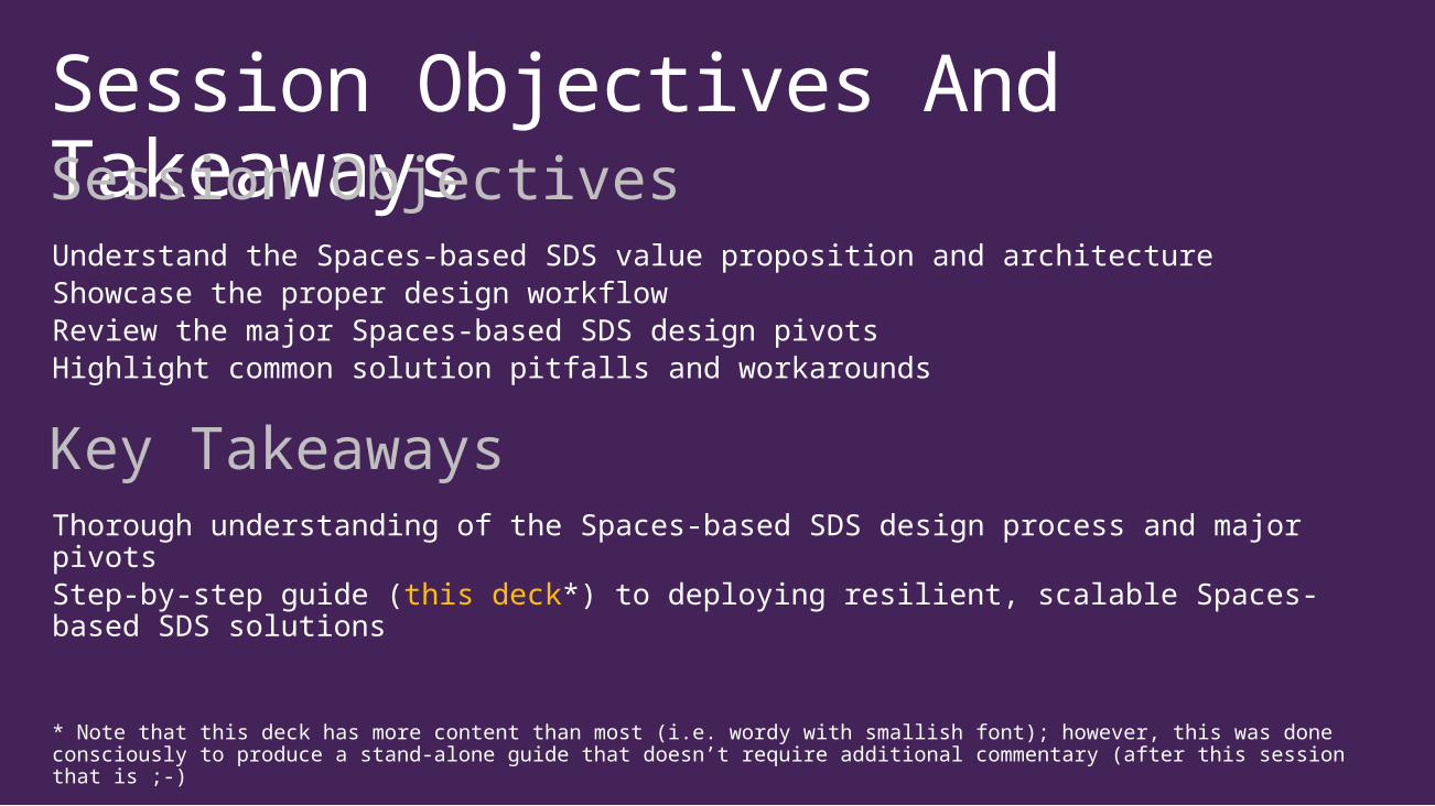
Session Objectives And TakeawaysSession Objectives Understand the Spaces-based SDS value proposition and architectureShowcase the proper design workflowReview the major Spaces-based SDS design pivotsHighlight common solution pitfalls and workarounds
Key TakeawaysThorough understanding of the Spaces-based SDS design process and major pivotsStep-by-step guide (this deck*) to deploying resilient, scalable Spaces-based SDS solutions
* Note that this deck has more content than most (i.e. wordy with smallish font); however, this was done consciously to produce a stand-alone guide that doesn’t require additional commentary (after this session that is ;-)
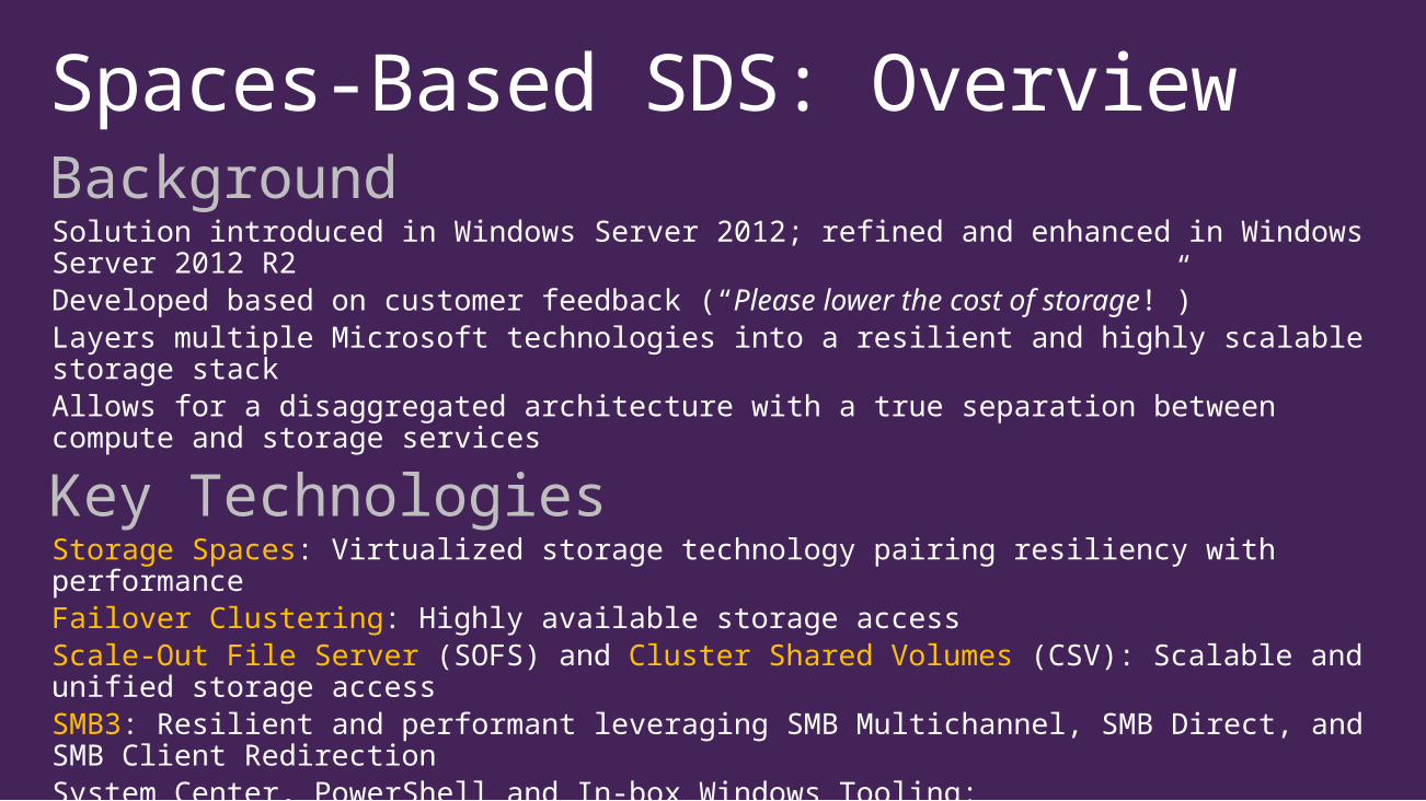
Spaces-Based SDS: OverviewBackgroundSolution introduced in Windows Server 2012; refined and enhanced in Windows Server 2012 R2Developed based on customer feedback (“Please lower the cost of storage!”)Layers multiple Microsoft technologies into a resilient and highly scalable storage stackAllows for a disaggregated architecture with a true separation between compute and storage services
Key TechnologiesStorage Spaces: Virtualized storage technology pairing resiliency with performanceFailover Clustering: Highly available storage accessScale-Out File Server (SOFS) and Cluster Shared Volumes (CSV): Scalable and unified storage accessSMB3: Resilient and performant leveraging SMB Multichannel, SMB Direct, and SMB Client RedirectionSystem Center, PowerShell and In-box Windows Tooling: Management/configuration/troubleshooting
Value PropositionFlexible, low-cost storage solutions based entirely on commodity hardware and Microsoft software
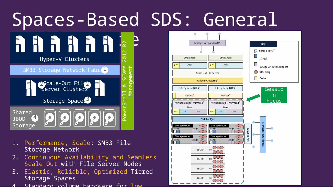
Spaces-Based SDS: General Architecture
Scale-Out FileServer Clusters
Storage Spaces
Hyper-V Clusters
SMB3 Storage Network Fabric
Shared JBODStorage
Pow
erS
hell
& S
CV
MM
2012 R
2
Managem
ent
1. Performance, Scale: SMB3 File Storage Network
2. Continuous Availability and Seamless Scale Out with File Server Nodes
3. Elastic, Reliable, Optimized Tiered Storage Spaces
4. Standard volume hardware for low cost
1
2 2
3
4
Session Focus

Spaces-Based SDS: Getting StartedTypical Customer Starting Point
Suggested Architectural Response
“I need a storage subsystem that can
support 500,000 IOPS.”
“That’s a great data point. Let’s talk through a few
others.”

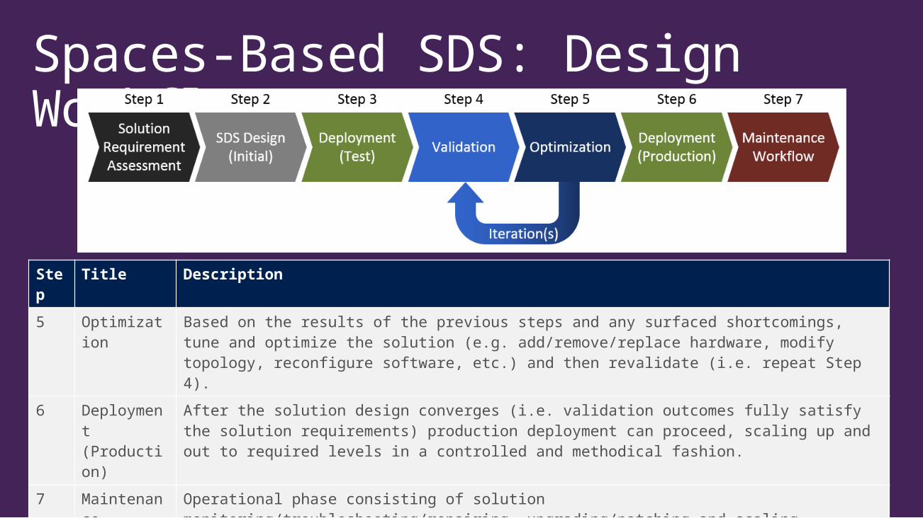
Spaces-Based SDS: Design Workflow
Step
Title Description
1 Solution Requirement Assessment
Identification and qualification/quantification of the key solution requirements, variables, pivots and endpoints, including details around the definition of a successful solution.
2 SDS Design (Initial)
Process of matching the solution requirements with the available solution building blocks (e.g. hardware and software) and best-practice design patterns (e.g. topologies and configurations).
3 Deployment (Test)
Actual hardware and software deployment of the initial SDS design, potentially in a more limited scale and/or Proof-of-Concept (PoC) environment.
4 Validation Ensure that all requirements outlined in Step 1 are acceptably satisfied or mitigated by the deployment. Initial validation iterations typically involve leveraging synthetic workloads (e.g. SQLIO, Iometer, etc.); however, later validation runs must include actual production workload patterns and scale.
Spaces-Based SDS: Design Workflow
Step
Title Description
5 Optimization
Based on the results of the previous steps and any surfaced shortcomings, tune and optimize the solution (e.g. add/remove/replace hardware, modify topology, reconfigure software, etc.) and then revalidate (i.e. repeat Step 4).
6 Deployment (Production)
After the solution design converges (i.e. validation outcomes fully satisfy the solution requirements) production deployment can proceed, scaling up and out to required levels in a controlled and methodical fashion.
7 Maintenance Workflow
Operational phase consisting of solution monitoring/troubleshooting/repairing, upgrading/patching and scaling.
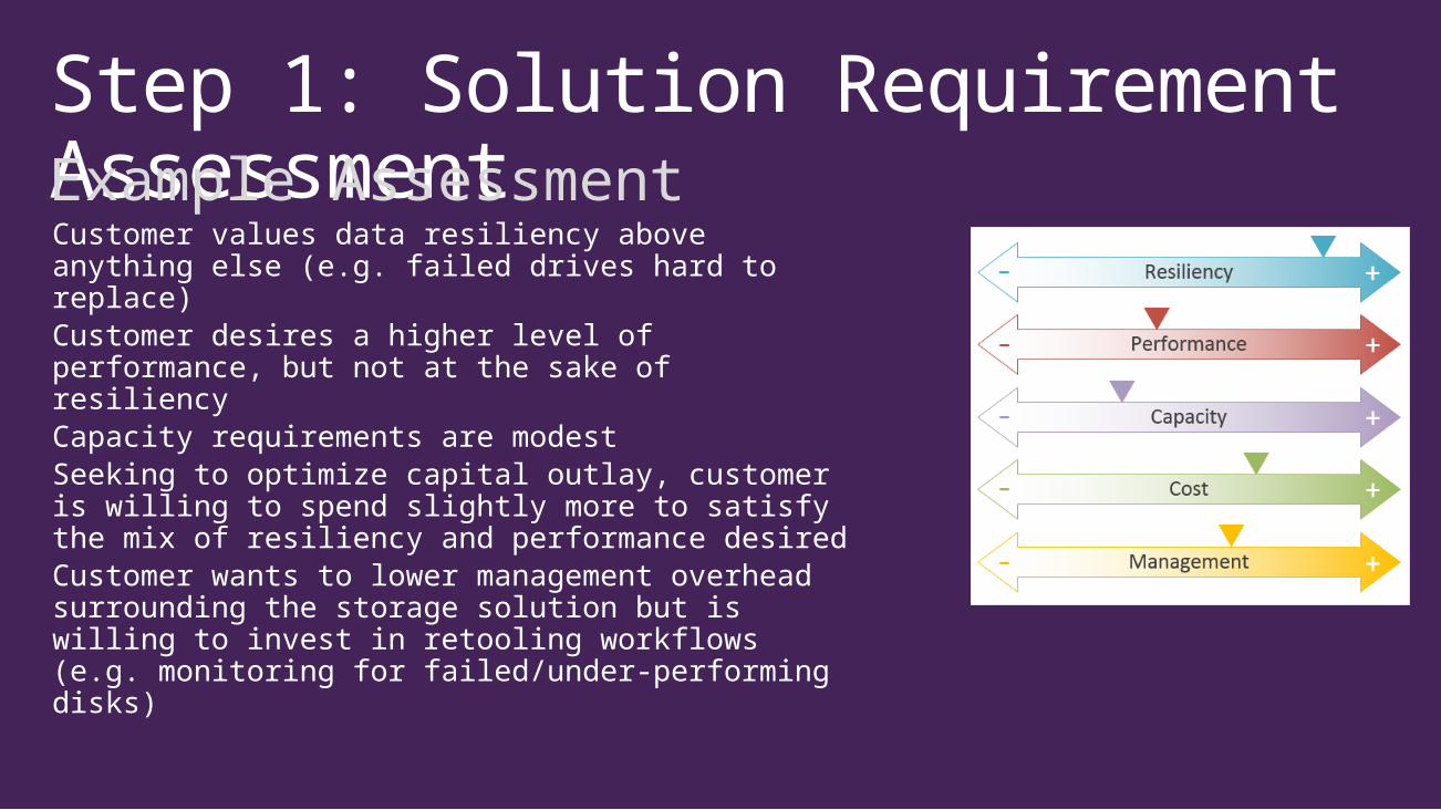
Step 1: Solution Requirement AssessmentExample AssessmentCustomer values data resiliency above anything else (e.g. failed drives hard to replace)Customer desires a higher level of performance, but not at the sake of resiliencyCapacity requirements are modestSeeking to optimize capital outlay, customer is willing to spend slightly more to satisfy the mix of resiliency and performance desiredCustomer wants to lower management overhead surrounding the storage solution but is willing to invest in retooling workflows (e.g. monitoring for failed/under-performing disks)
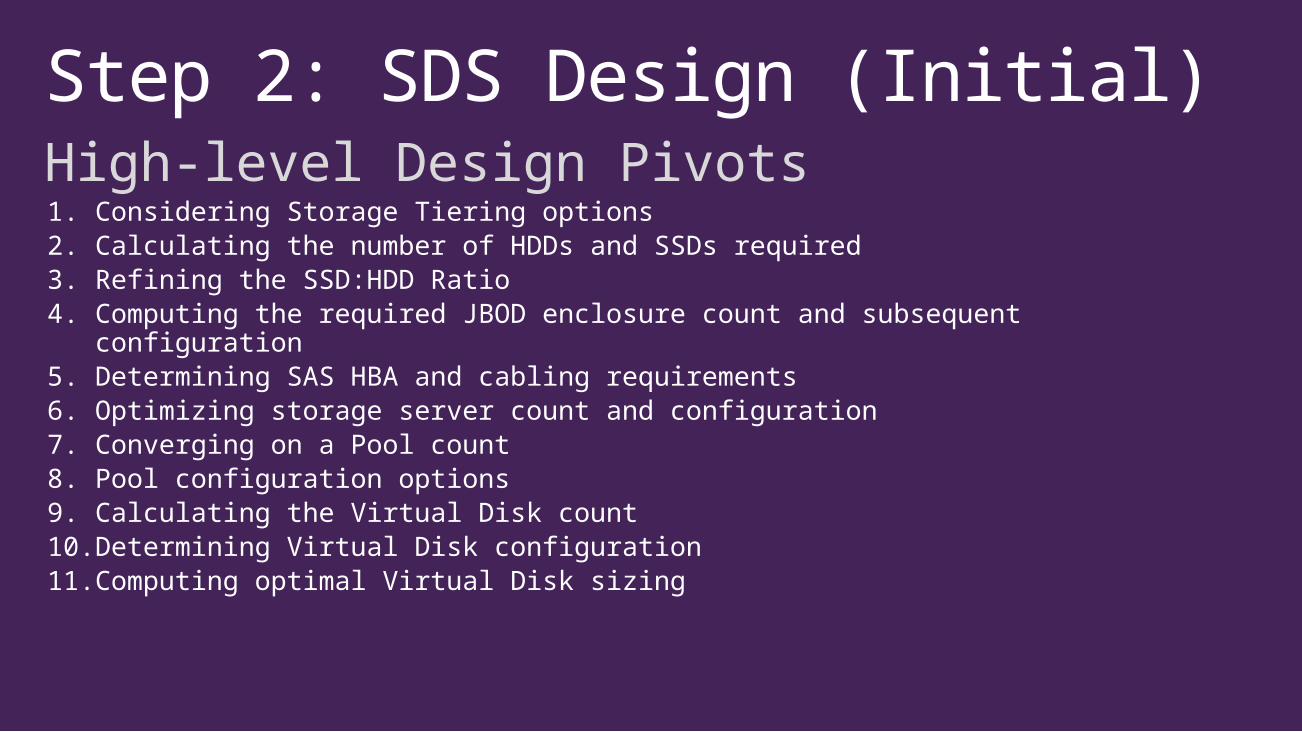
Step 2: SDS Design (Initial) High-level Design Pivots1. Considering Storage Tiering options2. Calculating the number of HDDs and SSDs required3. Refining the SSD:HDD Ratio4. Computing the required JBOD enclosure count and subsequent
configuration5. Determining SAS HBA and cabling requirements6. Optimizing storage server count and configuration7. Converging on a Pool count8. Pool configuration options9. Calculating the Virtual Disk count10. Determining Virtual Disk configuration11. Computing optimal Virtual Disk sizing

Overarching Solution Design PrinciplesAll implemented storage hardware should be properly certified.
All software should be running the latest recommended updates and patches (this includes Firmware).
Whenever possible, keep system components and configurations consistent and symmetrical.
Design for failures and plan for the subsequent workflows.

Example: The importance of Firmware
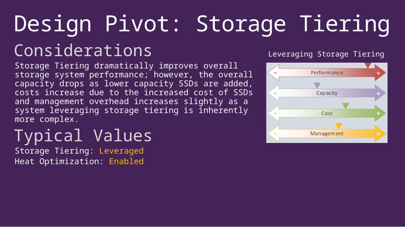
Design Pivot: Storage TieringConsiderationsStorage Tiering dramatically improves overall storage system performance; however, the overall capacity drops as lower capacity SSDs are added, costs increase due to the increased cost of SSDs and management overhead increases slightly as a system leveraging storage tiering is inherently more complex.
Typical ValuesStorage Tiering: LeveragedHeat Optimization: Enabled
Leveraging Storage Tiering

Design Pivot: HDD Type and CountConsiderationsThe type, size and count of the HDDs present should reflect the desired overall storage subsystem capacity.Both SAS and NL-SAS disks are supported; however, the additional cost incurred with high performing HDDs (e.g. 10K and 15K drives with large caches) typically isn’t necessary when utilizing Storage Tiering with SSDs.
Typical Values*Disk Size/Type: 2- 4TB NL-SAS HDDDisk Make/Model: UniformDisk Firmware: Latest
* All typical values listed throughout this guide reflect current best-practices supporting virtualized workloads. Other workloads require additional consideration and validation.

Design Pivot: HDD Type and CountBase Computation*Storage Based
Performance Based
* Designed only to give a starting point for the design.
Design Pivot: SSD Type and CountConsiderationsThe type, size and count of the SSDs present should reflect the desired maximum storage system performance. Increasing the total capacity of the SSD footprint allows for more of the IO working set to be moved to the faster tier by the tiering engine (post-processing), resulting in increased performance.Because the column count of a Virtual Disk must be the same for both tiers, increasing the number of SSD disks usually allows for greater column counts (since there are typically significantly fewer SSDs than HDDs in a given configuration) and thus greater HDD tier performance.
Typical ValuesDisk Size/Type: 200 - 800GB MLCDisk Make/Model: UniformDisk Firmware: Latest
Design Pivot: SSD Type and CountBase Computation*
* Designed only to give a starting point for the design. SSD quantities are usually increased well beyond the theoretical minimum needed to satisfy performance requirements due to additional factors.
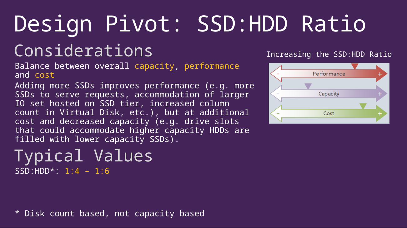
Design Pivot: SSD:HDD RatioConsiderationsBalance between overall capacity, performance and costAdding more SSDs improves performance (e.g. more SSDs to serve requests, accommodation of larger IO set hosted on SSD tier, increased column count in Virtual Disk, etc.), but at additional cost and decreased capacity (e.g. drive slots that could accommodate higher capacity HDDs are filled with lower capacity SSDs).
Typical ValuesSSD:HDD*: 1:4 – 1:6
* Disk count based, not capacity based
Increasing the SSD:HDD Ratio

Design Pivot: Enclosure Config and CountConsiderationsEnclosures specifications vary greatly: drive slot count, SAS port counts, etc.Using multiple enclosures allows for enclosure-level redundancy (via enclosure awareness); however, it also increases the space required for Fast RebuildMaintain hardware symmetry across all enclosures (cabling and disk layout)
Typical ValuesEnclosure Count: >=2IO Modules/Enclosure: 2Enclosure Make/Model: Uniform and CertifiedEnclosure Firmware: LatestDisk layout: Symmetrical across enclosures
Increasing Enclosure Count
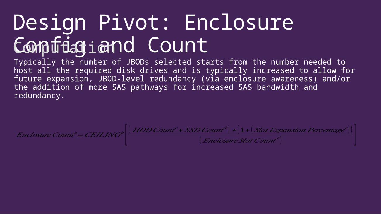
Design Pivot: Enclosure Config and CountComputationTypically the number of JBODs selected starts from the number needed to host all the required disk drives and is typically increased to allow for future expansion, JBOD-level redundancy (via enclosure awareness) and/or the addition of more SAS pathways for increased SAS bandwidth and redundancy.
𝐸𝑛𝑐𝑙𝑜𝑠𝑢𝑟𝑒𝐶𝑜𝑢𝑛𝑡𝑎=𝐶𝐸𝐼𝐿𝐼𝑁𝐺𝑏 [ ( 𝐻𝐷𝐷𝐶𝑜𝑢𝑛𝑡𝑐+𝑆𝑆𝐷𝐶𝑜𝑢𝑛𝑡𝑑 )∗ (1+ (𝑆𝑙𝑜𝑡 𝐸𝑥𝑝𝑎𝑛𝑠𝑖𝑜𝑛𝑃𝑒𝑟𝑐𝑒𝑛𝑡𝑎𝑔𝑒𝑒) )(𝐸𝑛𝑐𝑙𝑜𝑠𝑢𝑟𝑒𝑆𝑙𝑜𝑡 𝐶𝑜𝑢𝑛𝑡 𝑓 ) ]
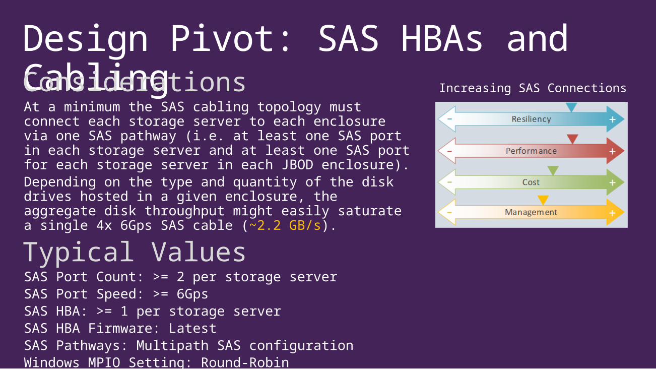
Design Pivot: SAS HBAs and CablingConsiderationsAt a minimum the SAS cabling topology must connect each storage server to each enclosure via one SAS pathway (i.e. at least one SAS port in each storage server and at least one SAS port for each storage server in each JBOD enclosure).Depending on the type and quantity of the disk drives hosted in a given enclosure, the aggregate disk throughput might easily saturate a single 4x 6Gps SAS cable (~2.2 GB/s).
Typical ValuesSAS Port Count: >= 2 per storage serverSAS Port Speed: >= 6GpsSAS HBA: >= 1 per storage serverSAS HBA Firmware: LatestSAS Pathways: Multipath SAS configurationWindows MPIO Setting: Round-Robin
Increasing SAS Connections
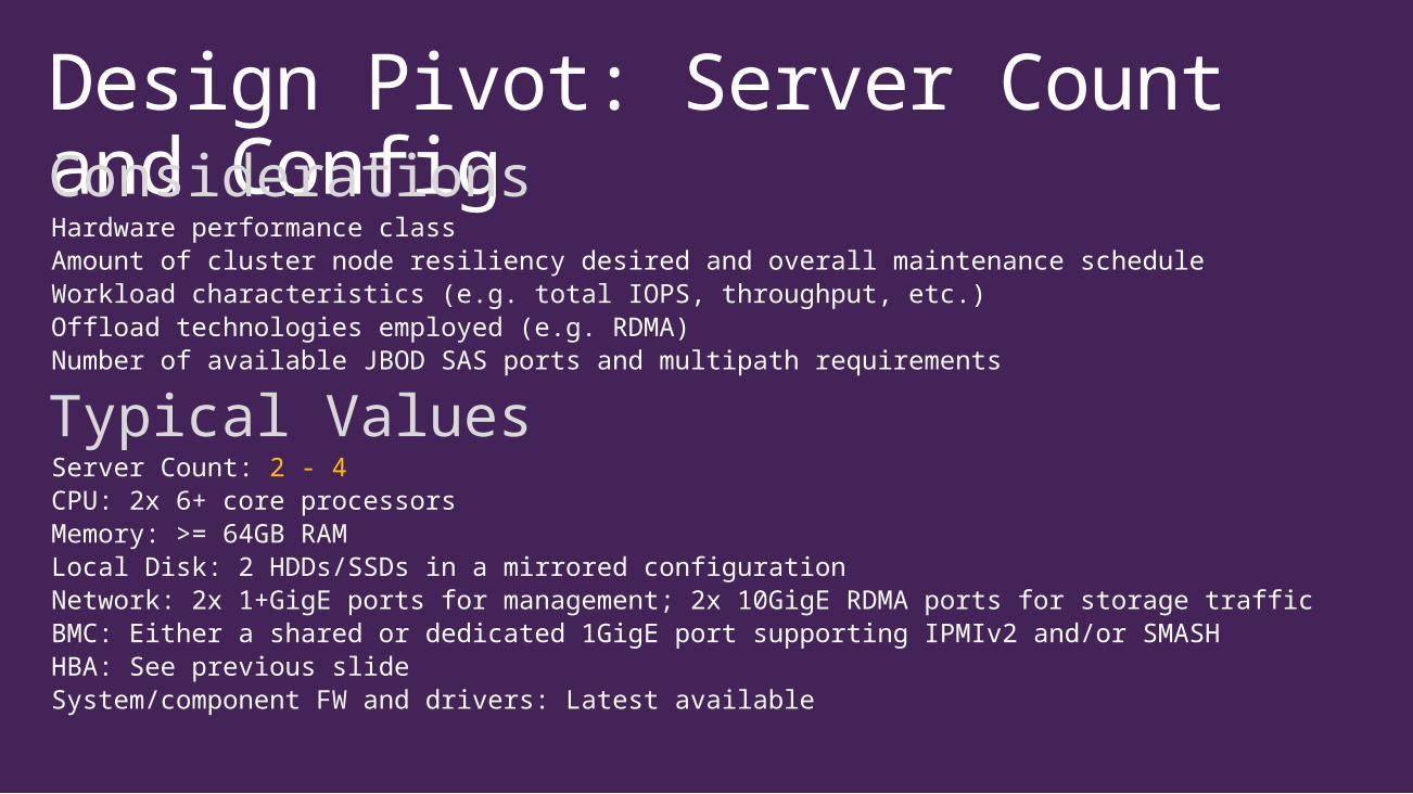
Design Pivot: Server Count and ConfigConsiderationsHardware performance classAmount of cluster node resiliency desired and overall maintenance scheduleWorkload characteristics (e.g. total IOPS, throughput, etc.)Offload technologies employed (e.g. RDMA)Number of available JBOD SAS ports and multipath requirements
Typical ValuesServer Count: 2 - 4CPU: 2x 6+ core processorsMemory: >= 64GB RAMLocal Disk: 2 HDDs/SSDs in a mirrored configurationNetwork: 2x 1+GigE ports for management; 2x 10GigE RDMA ports for storage trafficBMC: Either a shared or dedicated 1GigE port supporting IPMIv2 and/or SMASHHBA: See previous slideSystem/component FW and drivers: Latest available
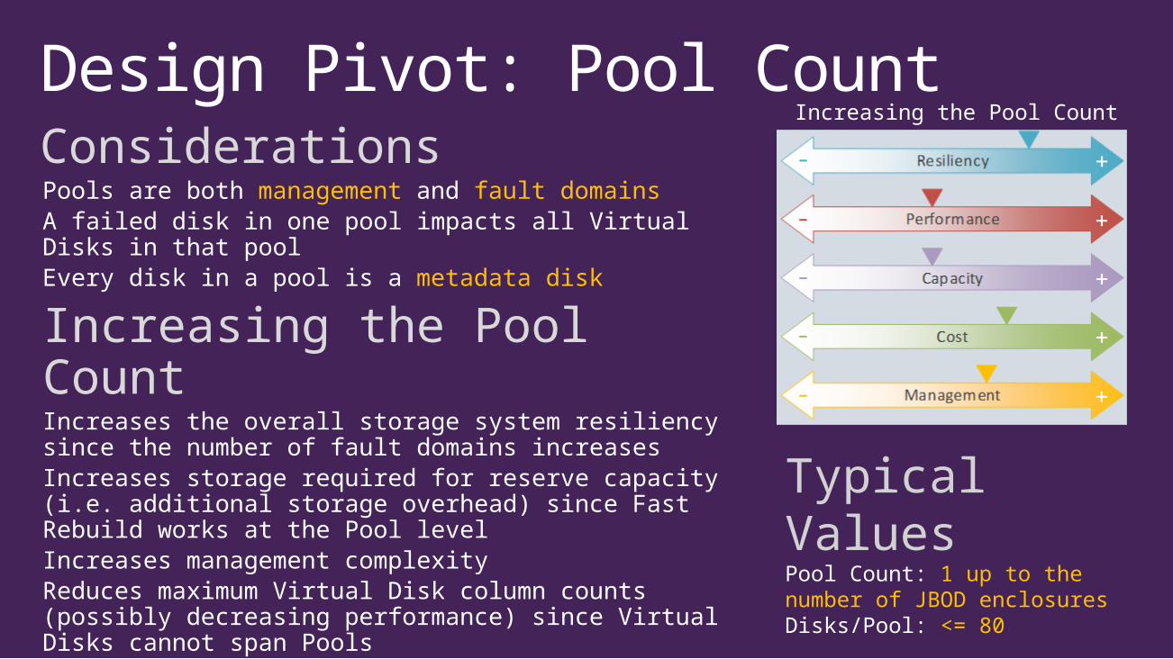
Design Pivot: Pool CountConsiderationsPools are both management and fault domainsA failed disk in one pool impacts all Virtual Disks in that poolEvery disk in a pool is a metadata disk
Increasing the Pool CountIncreases the overall storage system resiliency since the number of fault domains increases Increases storage required for reserve capacity (i.e. additional storage overhead) since Fast Rebuild works at the Pool levelIncreases management complexityReduces maximum Virtual Disk column counts (possibly decreasing performance) since Virtual Disks cannot span PoolsDecreases the time for Pool metadata tasks such as Virtual Disk rebuilds and clustered Pool failover (performance improvement)
Typical ValuesPool Count: 1 up to the number of JBOD enclosuresDisks/Pool: <= 80
Increasing the Pool Count

Design Pivot: Pool ConfigurationConsiderationsPools hold default configuration for associated Virtual Disks in addition to several settings that impact storage behavior:
Pool Option Details
RepairPolicy Sequential vs Parallel (lower IO hit but slower vs higher IO hit and faster)
RetireMissingPhysicalDisks
With Fast Rebuild, missing disks don’t cause a repair operation when set to Auto (requires Always)
IsPowerProtected True causes write-through operations to return before committed to disk. Power loss can lead to data corruption.
Typical ValuesHot Spares: NoFast Rebuild: YesRepairPolicy: Parallel (default)RetireMissingPhysicalDisks: Auto (default)IsPowerProtected: False (default)

Design Pivot: Virtual Disk CountConsiderations• The ratio of SMB shares servicing client data to the
underlying CSV and the backing Virtual Disk should be 1:1:1• Each tiered Virtual Disk accesses a dedicated WBC;
therefore, increasing the number of Virtual Disks may improve performance for certain workloads (all other things equal)
• Increasing the number of Virtual Disks increases management overhead (more things to manage)
• Increasing the number of workload Virtual Disks increases the ability to spread a failed node’s load across the cluster
Typical ValuesVirtual Disk Count: 2 - 4 per storage node
Increasing the Virtual Disk Count
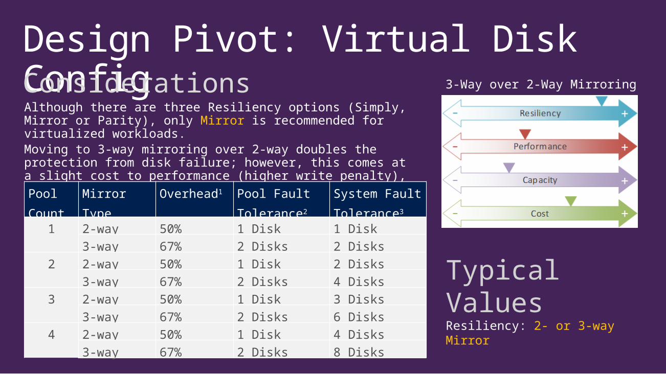
Design Pivot: Virtual Disk ConfigConsiderationsAlthough there are three Resiliency options (Simply, Mirror or Parity), only Mirror is recommended for virtualized workloads.Moving to 3-way mirroring over 2-way doubles the protection from disk failure; however, this comes at a slight cost to performance (higher write penalty), usable capacity decreases and costs subsequently increase.
Typical ValuesResiliency: 2- or 3-way Mirror
3-Way over 2-Way Mirroring
Pool Count
Mirror Type Overhead1 Pool Fault Tolerance2
System Fault Tolerance3
1 2-way 50% 1 Disk 1 Disk3-way 67% 2 Disks 2 Disks
2 2-way 50% 1 Disk 2 Disks3-way 67% 2 Disks 4 Disks
3 2-way 50% 1 Disk 3 Disks3-way 67% 2 Disks 6 Disks
4 2-way 50% 1 Disk 4 Disks3-way 67% 2 Disks 8 Disks
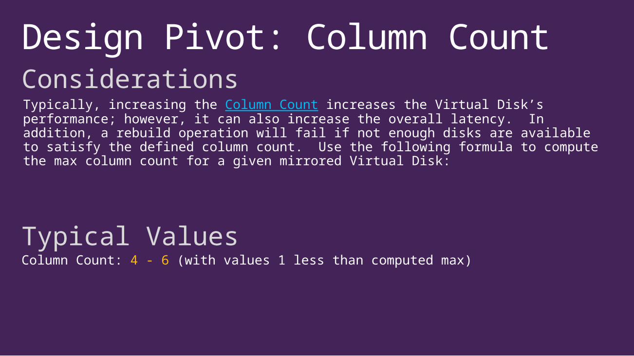
Design Pivot: Column CountConsiderationsTypically, increasing the Column Count increases the Virtual Disk’s performance; however, it can also increase the overall latency. In addition, a rebuild operation will fail if not enough disks are available to satisfy the defined column count. Use the following formula to compute the max column count for a given mirrored Virtual Disk:
Typical ValuesColumn Count: 4 - 6 (with values 1 less than computed max)
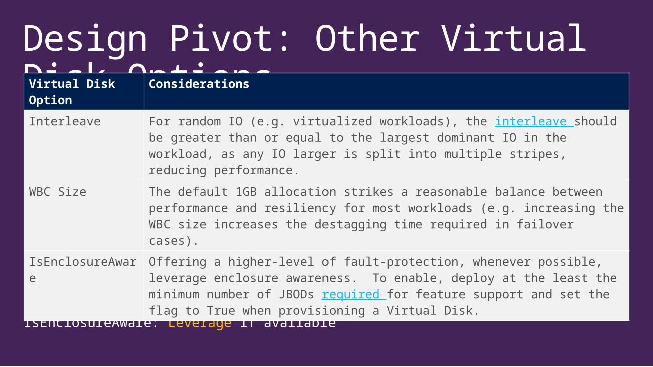
Design Pivot: Other Virtual Disk Options
Typical ValuesInterleave: 256K (default)WBC Size: 1GB (default)IsEnclosureAware: Leverage if available
Virtual Disk Option
Considerations
Interleave For random IO (e.g. virtualized workloads), the interleave should be greater than or equal to the largest dominant IO in the workload, as any IO larger is split into multiple stripes, reducing performance.
WBC Size The default 1GB allocation strikes a reasonable balance between performance and resiliency for most workloads (e.g. increasing the WBC size increases the destagging time required in failover cases).
IsEnclosureAware Offering a higher-level of fault-protection, whenever possible, leverage enclosure awareness. To enable, deploy at the least the minimum number of JBODs required for feature support and set the flag to True when provisioning a Virtual Disk.

Design Pivot: Virtual Disk SizeConsiderationsComputing the optimal size of a Pool’s Virtual Disks requires separate computations and subsequent summation of the optimal sizes of the Virtual Disk’s tiers. Adequate space needs to remain unallocated to properly allow for Fast Rebuild operation, as well as account for Storage Spaces metadata overhead and internal rounding allocations.
Computation
a: Conservative computation, leaving slightly more unallocated space in the pool than the minimum required for proper Fast Rebuild operation. Value in GiB (a power of 2 rather than GB, a power of 10).b: Value in GiBc: Reserved space for Storage Spaces metadata (all disks in a pool are metadata disks and contain both Pool and Virtual Disk metadata)d: Reserved overhead for Fast Rebuild: >=one disk’s capacity (+ 8GiB) per tier per pool per enclosuree: Tier sizes round up to the next multiple slab size, with a slab size equal to the size of a Storage Space extent (1GiB) times the number of columns; therefore round down to the closest tier size to stay underallocatedf: Write-back cache size, in GiB, for the tier in question (e.g. 1 for the SSD tier, 0 for the HDD tier using default values)g: Number of disks in the particular tier in the particular pool
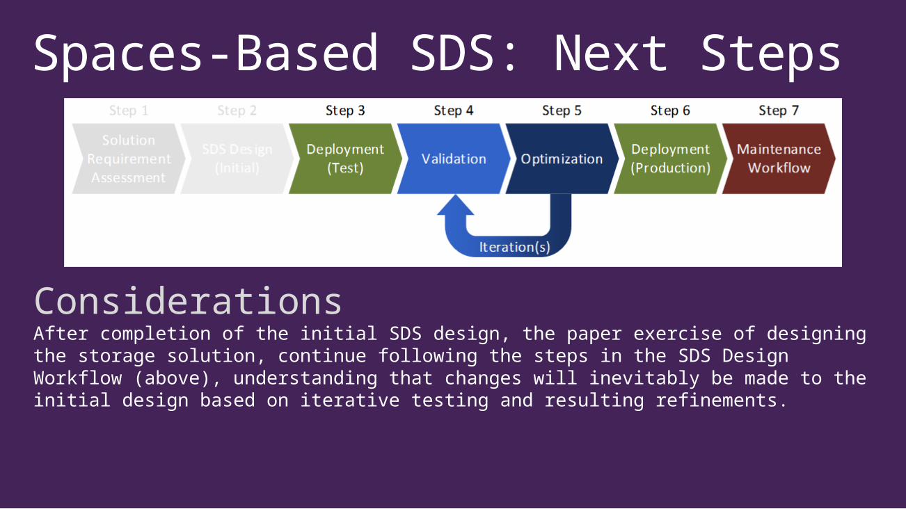
Spaces-Based SDS: Next Steps
ConsiderationsAfter completion of the initial SDS design, the paper exercise of designing the storage solution, continue following the steps in the SDS Design Workflow (above), understanding that changes will inevitably be made to the initial design based on iterative testing and resulting refinements.
Example/Demo
Putting It All Together
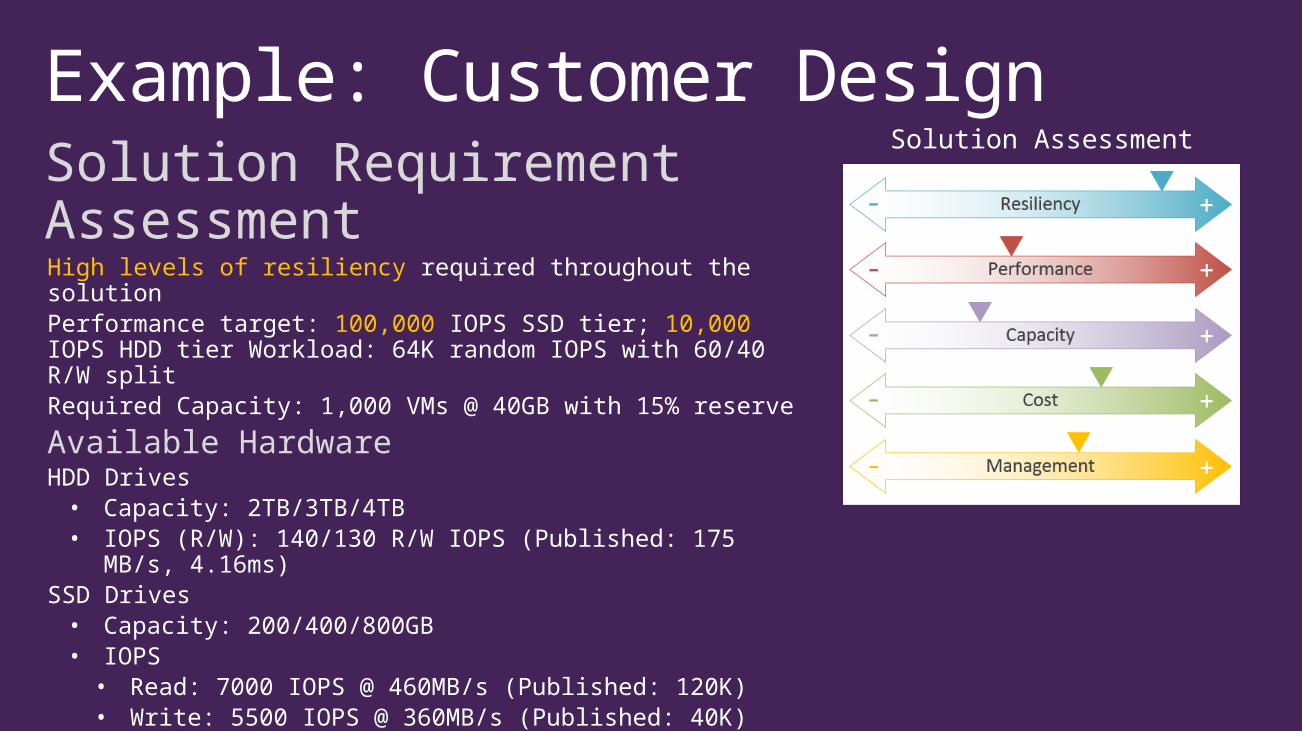
Example: Customer DesignSolution Requirement Assessment High levels of resiliency required throughout the solutionPerformance target: 100,000 IOPS SSD tier; 10,000 IOPS HDD tier Workload: 64K random IOPS with 60/40 R/W splitRequired Capacity: 1,000 VMs @ 40GB with 15% reserve
Available HardwareHDD Drives• Capacity: 2TB/3TB/4TB• IOPS (R/W): 140/130 R/W IOPS (Published: 175 MB/s,
4.16ms)SSD Drives• Capacity: 200/400/800GB• IOPS• Read: 7000 IOPS @ 460MB/s (Published: 120K)• Write: 5500 IOPS @ 360MB/s (Published: 40K)
Enclosures• 60 disk slots• 2 IO Modules w/ four SAS ports each
Solution Assessment
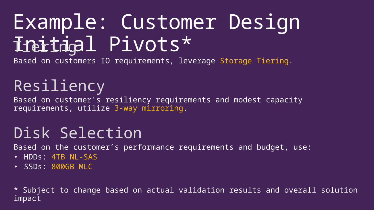
Example: Customer Design Initial Pivots*TieringBased on customers IO requirements, leverage Storage Tiering.
ResiliencyBased on customer's resiliency requirements and modest capacity requirements, utilize 3-way mirroring.
Disk SelectionBased on the customer’s performance requirements and budget, use:• HDDs: 4TB NL-SAS• SSDs: 800GB MLC
* Subject to change based on actual validation results and overall solution impact
Example: Customer DesignHDD CalculationStorage Based
Performance Based
Example: Customer DesignSSD Calculation
SDD:HDD Ratio Calculation
Enclosure Count

Example: Customer DesignEnclosure LayoutIncrease drive counts to allow for a symmetrical deployment and an optimized SSD:HDD ratio. Note that customer requests all enclosure drive slots be initially populated for simplified expansion.SSDs: 32 36HDDs: 136 144 (SSD:HDD 1:4)SSDs/Enclosure: 12HDDs/Enclosure: 48
SAS CablingBased on customers resiliency and IO requirements, leverage SAS Multipath cabling (i.e. two SAS paths from each storage server to each enclosure)Leverage 6 SAS ports per server (2 to each of the 3 enclosures)
Server CountBased on customer’s resiliency, IO, budget and multipath requirements, utilize 3 storage servers
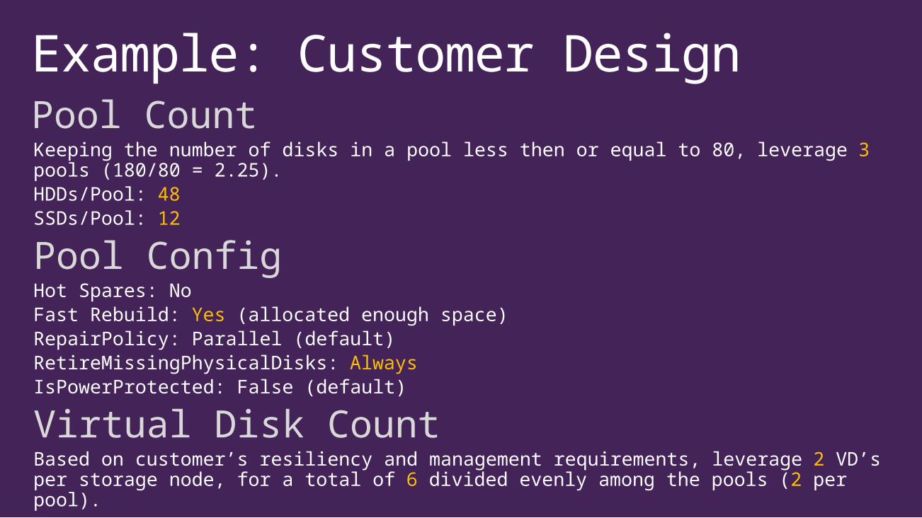
Example: Customer DesignPool CountKeeping the number of disks in a pool less then or equal to 80, leverage 3 pools (180/80 = 2.25).HDDs/Pool: 48SSDs/Pool: 12
Pool ConfigHot Spares: NoFast Rebuild: Yes (allocated enough space)RepairPolicy: Parallel (default)RetireMissingPhysicalDisks: AlwaysIsPowerProtected: False (default)
Virtual Disk CountBased on customer’s resiliency and management requirements, leverage 2 VD’s per storage node, for a total of 6 divided evenly among the pools (2 per pool).
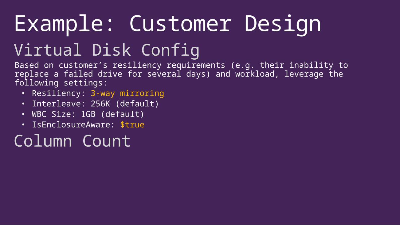
Example: Customer DesignVirtual Disk ConfigBased on customer’s resiliency requirements (e.g. their inability to replace a failed drive for several days) and workload, leverage the following settings:• Resiliency: 3-way mirroring• Interleave: 256K (default)• WBC Size: 1GB (default)• IsEnclosureAware: $true
Column Count
Example: Customer DesignVirtual Disk Sizing
SSD Tier
HDD Tier
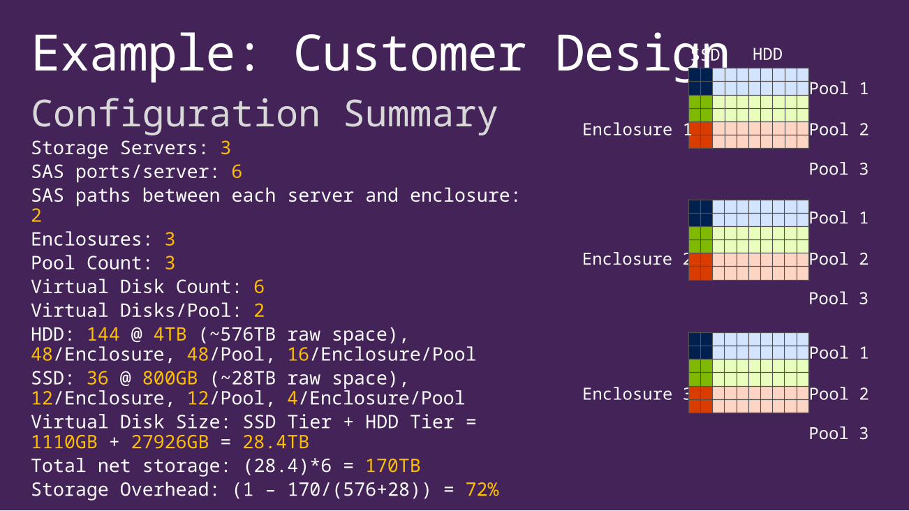
Example: Customer DesignConfiguration SummaryStorage Servers: 3SAS ports/server: 6SAS paths between each server and enclosure: 2Enclosures: 3Pool Count: 3Virtual Disk Count: 6Virtual Disks/Pool: 2HDD: 144 @ 4TB (~576TB raw space), 48/Enclosure, 48/Pool, 16/Enclosure/PoolSSD: 36 @ 800GB (~28TB raw space), 12/Enclosure, 12/Pool, 4/Enclosure/PoolVirtual Disk Size: SSD Tier + HDD Tier = 1110GB + 27926GB = 28.4TBTotal net storage: (28.4)*6 = 170TBStorage Overhead: (1 – 170/(576+28)) = 72%
Pool 1
Pool 2
Pool 3
Enclosure 1
SSD HDD
Pool 1
Pool 2
Pool 3
Enclosure 2
Pool 1
Pool 2
Pool 3
Enclosure 3
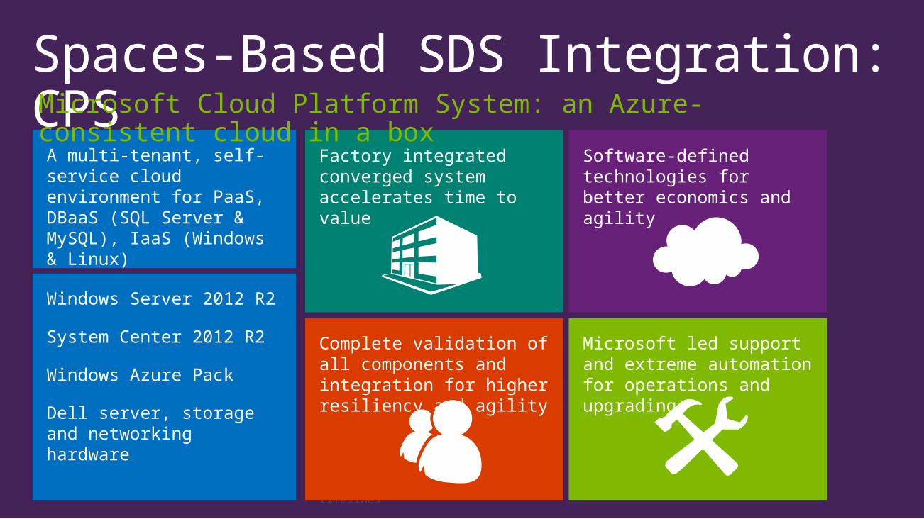
Spaces-Based SDS Integration: CPS
On-premises innovation with AzureConsistent public, private, and hybrid cloud experiences
Multitenant, self-service consumption on shared infrastructure
Resilient fabric for greater availability and system agility
Software-defined datacenterEfficient use of hardware through an innovative software layer
Rich catalog of tenant services
Optimal platform for Microsoft apps
Validated from the ground upEnd-to-end testing and validation of devices, firmware, and software
Management of factory integration and onsite deployment by Microsoft
Predictable order to live timelines
Single-vendor supportCentralized incident management provided by Microsoft
Onboard monitoring of hardware, resources, and services
Validation of performance and scale benchmarks by Microsoft
Microsoft led support and extreme automation for operations and upgrading
Complete validation of all components and integration for higher resiliency and agility
Software-defined technologies for better economics and agility
Factory integrated converged system accelerates time to value
A multi-tenant, self-service cloud environment for PaaS, DBaaS (SQL Server & MySQL), IaaS (Windows & Linux)
Windows Server 2012 R2
System Center 2012 R2
Windows Azure Pack
Dell server, storage and networking hardware
Microsoft Cloud Platform System: an Azure-consistent cloud in a box

Session Objectives And TakeawaysSession Objectives Understand the Spaces-based SDS value proposition and architectureShowcase the proper design workflowReview the major Spaces-based SDS design pivotsHighlight common solution pitfalls and workarounds
Key TakeawaysThorough understanding of the Spaces-based SDS design process and major pivotsStep-by-step guide (this deck*) to deploying resilient, scalable Spaces-based SDS solutions
* Note that this deck has more content than most (i.e. wordy with smallish font); however, this was done consciously to produce a stand-alone guide that doesn’t require additional commentary (after this session that is ;-)
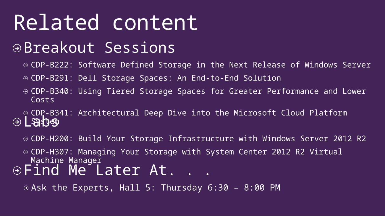
Breakout SessionsCDP-B222: Software Defined Storage in the Next Release of Windows Server
CDP-B291: Dell Storage Spaces: An End-to-End Solution
CDP-B340: Using Tiered Storage Spaces for Greater Performance and Lower Costs
CDP-B341: Architectural Deep Dive into the Microsoft Cloud Platform System
Related content
Find Me Later At. . .Ask the Experts, Hall 5: Thursday 6:30 – 8:00 PM
LabsCDP-H200: Build Your Storage Infrastructure with Windows Server 2012 R2
CDP-H307: Managing Your Storage with System Center 2012 R2 Virtual Machine Manager
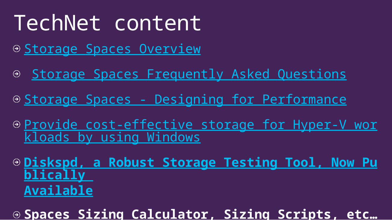
Storage Spaces Overview
Storage Spaces Frequently Asked Questions
Storage Spaces - Designing for Performance
Provide cost-effective storage for Hyper-V workloads by using Windows
Diskspd, a Robust Storage Testing Tool, Now Publically Available
Spaces Sizing Calculator, Sizing Scripts, etc…(forthcoming)
TechNet content

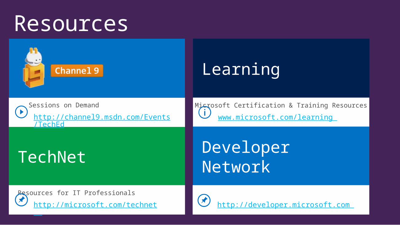
Resources
Learning
Microsoft Certification & Training Resources
www.microsoft.com/learning
Developer Network
http://developer.microsoft.com
TechNet
Resources for IT Professionals
http://microsoft.com/technet
Sessions on Demand
http://channel9.msdn.com/Events/TechEd
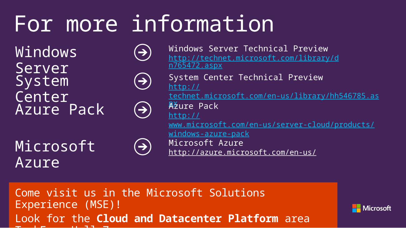
Come visit us in the Microsoft Solutions Experience (MSE)!Look for the Cloud and Datacenter Platform area TechExpo Hall 7
For more informationWindows Server Technical Previewhttp://technet.microsoft.com/library/dn765472.aspx
Windows Server
Microsoft Azure
Microsoft Azurehttp://azure.microsoft.com/en-us/
System Center
System Center Technical Previewhttp://technet.microsoft.com/en-us/library/hh546785.aspx
Azure Pack Azure Packhttp://www.microsoft.com/en-us/server-cloud/products/windows-azure-pack
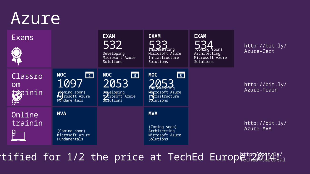
Azure
Implementing Microsoft Azure Infrastructure Solutions
Classroomtraining
Exams
+
(Coming soon)Microsoft Azure Fundamentals
Developing Microsoft Azure Solutions
MOC
10979
Implementing Microsoft Azure Infrastructure Solutions
Onlinetraining
(Coming soon)Architecting Microsoft Azure Solutions
(Coming soon)Architecting Microsoft Azure Solutions
Developing Microsoft Azure Solutions
(Coming soon)Microsoft Azure Fundamentals
http://bit.ly/Azure-Cert
http://bit.ly/Azure-MVA
http://bit.ly/Azure-Train
Get certified for 1/2 the price at TechEd Europe 2014!http://bit.ly/TechEd-CertDeal
2 5 5MOC
20532
MOC
20533
EXAM
532EXAM
533EXAM
534
MVA MVA

Please Complete An Evaluation FormYour input is important!TechEd Schedule Builder CommNet station or PC
TechEd Mobile appPhone or Tablet
QR code

Evaluate this session
Resources
Learning
Microsoft Certification & Training Resources
www.microsoft.com/learning
Developer Network
http://developer.microsoft.com
TechNet
Resources for IT Professionals
http://microsoft.com/technet
Sessions on Demand
http://channel9.msdn.com/Events/TechEd

© 2014 Microsoft Corporation. All rights reserved. Microsoft, Windows, and other product names are or may be registered trademarks and/or trademarks in the U.S. and/or other countries.The information herein is for informational purposes only and represents the current view of Microsoft Corporation as of the date of this presentation. Because Microsoft must respond to changing market conditions, it should not be interpreted to be a commitment on the part of Microsoft, and Microsoft cannot guarantee the accuracy of any information provided after the date of this presentation. MICROSOFT MAKES NO WARRANTIES, EXPRESS, IMPLIED OR STATUTORY, AS TO THE INFORMATION IN THIS PRESENTATION.