cdma2000®1 1xrtt / 1xev-do hybrid mode testing · pdf filecdma2000®1 1xrtt / 1xev-do...
TRANSCRIPT

Rohde & Schwarz Products: Radio Communication Tester R&S® CMU200
CDMA2000®1 1xRTT / 1xEV-DO Hybrid Mode Testing
This application note is intended as a guide to configuring the R&S® CMU200 instrument for CDMA2000 1xEV-DO / 1xRTT Hybrid Mode testing.
Subject to change – T. Opferman, 9.2007 – 1CM 65_2

CDMA2000 1xRTT / 1xEV-DO Hybrid Mode Testing
1CM 65_2 2 Rohde & Schwarz
Contents 1 Introduction ............................................................................................. 3 2 Definitions ............................................................................................... 3 3 CDMA2000 Hybrid Mode Overview........................................................ 3 4 R&S® CMU200 Hybrid Mode Configuration............................................ 5
Hybrid Mode Setup Equipment List ................................................... 6 CDMA2000 Tx/Rx RF Signal Configuration ...................................... 7 External Trigger (AUX3) Configuration.............................................. 8 External Reference Signal Configuration .......................................... 9 CDMA system time Synchronization ............................................... 11
5 Access Terminal Hybrid Mode Configuration ....................................... 21 6 CDMA2000 Hybrid Mode Tests ............................................................ 22
Voice Call Termination during 1xEV-DO Data Call ......................... 22 Voice Call Origination during 1xEV-DO Data Call ........................... 23 SMS during 1xEV-DO Data Call ...................................................... 24 Intra-PDSN Active Data Handoff from 1xEV-DO to 1xRTT............. 25 Examples of Additional Supported Hybrid Test Scenarios.............. 31
7 References............................................................................................ 32 8 R&S® CMU200 Ordering Information.................................................... 32 9 Appendix A – Quick How To ................................................................. 33 10 Appendix B – GPIB Sequence.............................................................. 34

CDMA2000 1xRTT / 1xEV-DO Hybrid Mode Testing
1CM 65_2 3 Rohde & Schwarz
1 Introduction CDMA2000 networks provide the capability for mobile devices to operate in both CDMA2000 1xRTT and CDMA2000 1xEV-DO systems simultaneously. This application note describes how the R&S® CMU200 can be used as a turnkey solution for testing mobile devices in this dual system environment. The first part of the application note describes how to configure the R&S® CMU200 and mobile devices in order to test the conformance of hybrid mode devices. The second part of the application note describes some of the test scenarios possible using the R&S® solution.
2 Definitions 1xEV-DO – Evolution Data Only. Third-generation broadband wireless packet data technology optimized for high-speed mobile data.
1xRTT - 1 times Radio Transmission Technology is used to identify the version of CDMA2000 radio technology that operates in a pair (transmit and receive) of 1.25-MHz radio channels (one times 1.25 MHz). 1xRTT is also commonly referred to as CDMA2000.
Data Dedicated Transmission Mode (DDTM) – A mobile parameter which defines the preference for handling incoming speech calls while in a packet data connection (OFF = accept speech call; ON = send speech call directly to voice mail).
Hybrid Mode – Mode of operation for a mobile which is simultaneously monitoring CDMA2000 1xRTT and CDMA2000 1xEV-DO systems.
Number Assignment Modem (NAM) - The NAM is collection of internal parameters that define a working phone for a given network (phone number, access parameters, etc.). Packet Data Serving Node (PDSN) – A component of a CDMA2000 mobile network which acts as the connection point between the Radio Access and IP networks. This component is responsible for managing PPP sessions between the mobile provider's core IP network and the mobile station. PDSN Server Mode – configuration mode which allows for the PDSN functionality to reside in the R&S® CMU200. PDSN Client Mode – configuration mode which allows for the PDSN functionality to reside outside of the R&S® CMU200.
Preferred Roaming List (PRL) – The preferred roaming list specifies the frequencies and systems that the mobile uses during system selection. A preferred roaming list is stored in the mobile’s nonvolatile memory for each NAM that is supported.
3 CDMA2000 Hybrid Mode Overview A mobile with hybrid mode support is capable of supporting services on both CDMA2000 1xRTT and CDMA2000 1xEV-DO systems. The mobile acquires both systems and maintains registration and overhead information for both systems simultaneously. While operating in hybrid mode, the mobile can access either system.
The hybrid mode capabilities are summarized by the following use cases:

CDMA2000 1xRTT / 1xEV-DO Hybrid Mode Testing
1CM 65_2 4 Rohde & Schwarz
• Power Up
During power up, the mobile first searches for CDMA2000 1xRTT frequencies in accordance with the preferred roaming list and roaming preference settings and will register on the cell with the strongest signal level. Upon successful acquisition of the CDMA2000 1xRTT system, the mobile establishes a session on the best available CDMA2000 1xEV-DO frequency which is associated with the current CDMA2000 1xRTT system as defined in the preferred roaming list. After registering on the CDMA2000 1xRTT system and opening a session on the CDMA2000 1xEV-DO system, the AT will monitor the overhead information on both systems and respond to pages sent from either system.
In order to avoid collisions in time between the CDMA2000 1xRTT paging channel slot and the CDMA2000 1xEV-DO control channel cycle that the mobile listens to, the mobile negotiates the preferred CDMA2000 1xEV-DO control channel cycle. The preferred control channel cycle does not interfere with the paging channel slot and is negotiated during session negotiation.
• Origination/Termination of a CDMA2000 1xRTT voice call with an active CDMA2000 1xEV-DO data call
While the mobile has an open traffic channel allocated for a CDMA2000 1xEV-DO data call, the mobile continues to perform idle state procedures on the CDMA2000 1xRTT system. When it is time to decode the CDMA2000 1xRTT paging channel slot, the mobile will tune to the CDMA2000 1xRTT frequency. While the mobile is decoding the CDMA2000 1xRTT paging channel slot, the CDMA2000 1xEV-DO data call remains active, however, all 1xEV-DO data packets sent to the mobile during this time will not be decoded by the mobile and potentially retransmitted (depends on the data application) by the CDMA2000 1xEV-DO network. If the mobile detects an incoming page from the CDMA2000 1xRTT system, the page request will be processed by the mobile assuming the mobile’s Data Dedicated Transmission Mode (DDTM) setting is OFF. The mobile will transition the CDMA2000 1xEV-DO data call from a PPP connected state to a PPP dormant state and process the incoming page request.
In addition, the mobile may have the ability to originate a CDMA2000 1xRTT voice call during a CDMA2000 1xEV-DO data call.
• Origination/Termination of a CDMA2000 1xRTT voice call with a PPP dormant CDMA2000 1xEV-DO data session
While the mobile has a PPP dormant CDMA2000 1xEV-DO data session, the mobile performs idle state procedures on both the CDMA2000 1xRTT and CDMA2000 1xEV-DO systems. In the PPP dormant mode, the mobile has the ability to originate a voice call on the CDMA2000 1xRTT system, terminate a voice call on the CDMA2000 1xRTT system, or transition the data session to PPP connected and transmit data by establishing a traffic channel on the CDMA2000 1xEV-DO system.
• Hybrid Packet Data Handoffs
The mobile has the ability to handoff a data session to a CDMA2000 1xRTT system from a CDMA2000 1xEV-DO system or vice versa. In a situation where the cell’s signal level is lost or experiences degradation, the mobile can move its data session by initiating a new packet data call on the other system (either CDMA2000 1xRTT or CDMA2000 1xEV-DO). The Packet Data Serving Node (PDSN) will take care of routing the data over the new PPP connection. This test setup requires the two R&S® CMU200 systems to be equipped with the R&S® CMU-B83 Var 22 hardware option.

CDMA2000 1xRTT / 1xEV-DO Hybrid Mode Testing
1CM 65_2 5 Rohde & Schwarz
4 R&S® CMU200 Hybrid Mode Configuration The R&S® solution for testing hybrid mode requires synchronizing two R&S® CMU200 test instruments. One instrument is configured for CDMA2000 1xRTT operation and the other instrument is configured for CDMA2000 1xEV-DO operation. An instrument is then designated as the master and the other a slave. In the example configuration that follows, the instrument configured with CDMA2000 1xRTT is designated as the master.
Synchronizing the R&S® CMU200 test instruments involves the following procedures:
• Combining RF In/Out of the R&S® CMU200-Master and the R&S® CMU200-Slave instruments with a power splitter/combiner
• Connecting the AUX3 ports on both R&S® CMU200s to be used for output trigger (PP2S, Event Trigger) signals
• Configuring the R&S® CMU200-Master to source an external reference signal (10 MHz clock) for the R&S® CMU200-Slave
This procedure is optional since both instruments can also be configured to use a common external reference signal from an outside source.
• Configuring the R&S® CMU200-Master and the R&S® CMU200-Slave instruments to operate on the same CDMA system time
An Ethernet connection is required between R&S® CMU200-Master and the R&S® CMU200-Slave instruments if data testing is performed in the hybrid mode environment (see Section 6 – Intra-PDSN Active Data Handoff).
R&S® CMU200 - Master R&S® CMU200 - Slave
AUX3
Ref Out 1 Ref In
AUX3
PIN6PIN2
BNC-to-BNC
BNC-to-BNC
Ethernet (optional)
Figure 1. R&S® CMU200 Hybrid Mode test environment

CDMA2000 1xRTT / 1xEV-DO Hybrid Mode Testing
1CM 65_2 6 Rohde & Schwarz
Hybrid Mode Setup Equipment List
1. Two R&S® CMU200 instruments
The R&S® CMU200 operating as the master may be configured with either the R&S® CMU-B83 Var 22 board or R&S® CMU-B83 Var 12 board. The R&S® CMU200 operating as the slave must be configured with the CMU-B83 Var 22 board. If data testing is performed in the hybrid mode environment (see Section 6 – Intra-PDSN Active Data Handoff), both of the R&S® CMU200 instruments must be configured with the R&S® CMU-B83 Var 22 board.
In Figure1, the assignment of CDMA2000 1xRTT as the master and CDMA2000 1xEV-DO as the slave is done as an example for this application note. The assignment of master/slave could have been done the other way around. Again, the only restriction is that the slave instrument must have a CMU-B83 Var22 board installed.
2. Mobile which supports hybrid mode
3. Two BNC-to-BNC RF cables
4. One R&S® CMU-Z89 Hybrid Mode Test Kit. The test kit consists of :
• One power splitter/combiner (SMA connectors, 10MHz to 4.2GHz @-6dB) • Two N to SMA cables (1m length) • One SMA to N adapter • Two small boards with seven BNC jacks each with a flat-ribbon cable and plug
that connects into the AUX3 serial port on the R&S® CMU200 • Two BNC-to-BNC cables
5. (Optional) Ethernet cable used for connecting the R&S® CMU200-Master and the R&S® CMU200-Slave instruments. This connection is required for data testing in a hybrid mode environment. See Section 6 – Intra-PDSN Active Data Handoff.

CDMA2000 1xRTT / 1xEV-DO Hybrid Mode Testing
1CM 65_2 7 Rohde & Schwarz
CDMA2000 Tx/Rx RF Signal Configuration The R&S® CMU200-Master and R&S® CMU200-Slave RF signals are combined using the power splitter/combiner from the R&S® CMU-Z89 Hybrid Mode Test Kit.
Figure 2. Combined R&S® CMU200 RF Tx/Rx Signals
STEP 1 – Configure the RF Input and RF Output on both R&S® CMU200 instruments
Configure the R&S® CMU200-Master and the R&S® CMU200-Slave to use the bi-directional connector RF2 (or RF1).
The RF Output / RF Input parameters can be found at:
Connect Control: AF/RF Tab

CDMA2000 1xRTT / 1xEV-DO Hybrid Mode Testing
1CM 65_2 8 Rohde & Schwarz
The Ext. Att. Output softkey defines an external attenuation (or gain, if the value is negative) at the selected RF output. External attenuation is required if attenuation (such as a cable and/or a power splitter/combiner) is included in the test setup path, which is to be corrected by an increased signal level. If an external attenuation is defined, the output signal level is referenced to the input of the mobile. The generator level is therefore shifted with respect to the actual level at the output connector of the R&S® CMU200. See [1] for more details.
STEP 2 – Combine the RF In/Out Signals on the two R&S® CMU200 instruments
Connect the R&S® CMU200-Master and R&S® CMU200-Slave RF2 (or RF1) ports using the CMU-Z89’s power/splitter combiner.
External Trigger (AUX3) Configuration The R&S® CMU200-Master and R&S® CMU200-Slave AUX3 ports are connected using the BNC boards from the R&S® CMU-Z89 Hybrid Mode Test Kit. The AUX3 port on the R&S® CMU200-Master is used to provide output trigger signals (PP2S, Event Trigger) to the R&S® CMU200-Slave.
Figure 3. R&S® CMU200 AUX3 Port Connectivity

CDMA2000 1xRTT / 1xEV-DO Hybrid Mode Testing
1CM 65_2 9 Rohde & Schwarz
STEP 1 – From the front panel, connect the AUX3 ports on the two R&S® CMU200 instruments
Connect the R&S® CMU200-Master’s AUX3 port to the AUX3 breakout box from the R&S® CMU-Z89 Hybrid Mode Test Kit.
Connect the R&S® CMU200-Slave’s AUX3 port to the AUX3 breakout box from the R&S® CMU-Z89 Hybrid Mode Test Kit.
Using a BNC-to-BNC cable, connect PIN2 on the AUX3 breakout box attached to the R&S® CMU200-Master to PIN6 (Reserved for External Sync Trigger) on the AUX3 breakout box attached to the R&S® CMU200-Slave.
External Reference Signal Configuration The R&S® CMU200-Master is configured to source the external reference signal (10 MHz clock) for the R&S® CMU200-Slave.
Figure 4. R&S® CMU200 Reference Signal Connectivity
CDMA2000 1xRTT / 1xEV-DO Hybrid Mode Testing
1CM 65_2 10 Rohde & Schwarz
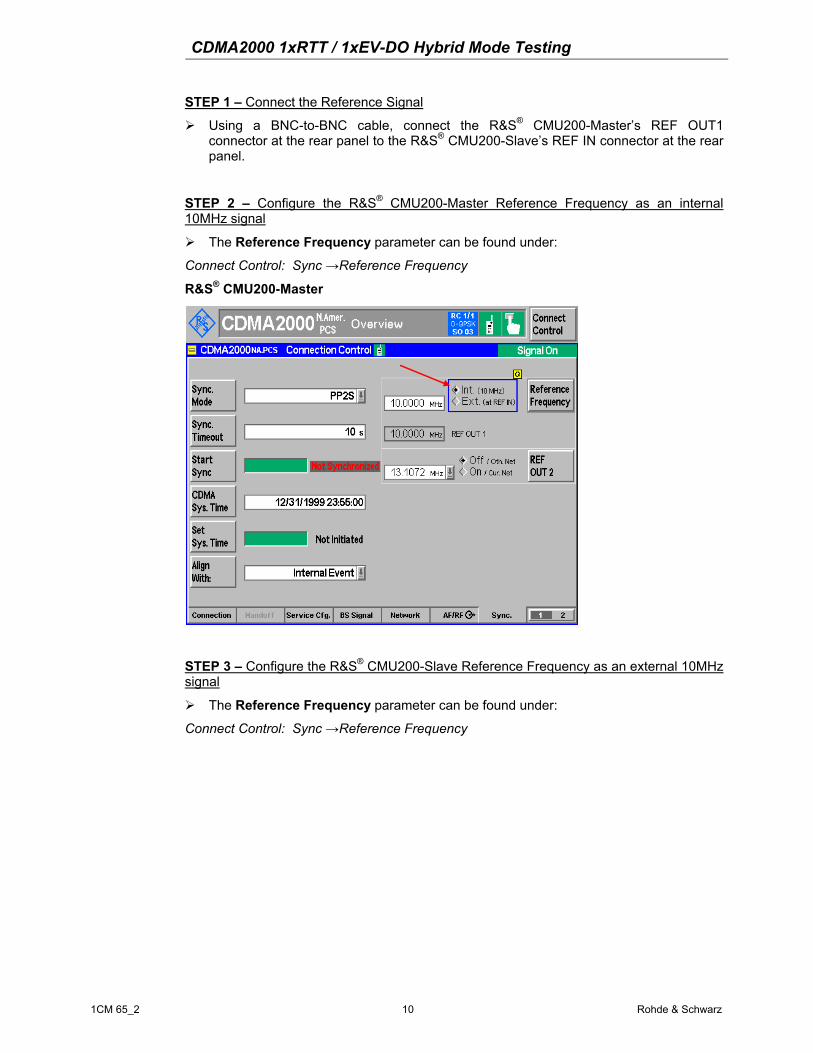
STEP 1 – Connect the Reference Signal
Using a BNC-to-BNC cable, connect the R&S® CMU200-Master’s REF OUT1 connector at the rear panel to the R&S® CMU200-Slave’s REF IN connector at the rear panel.
STEP 2 – Configure the R&S® CMU200-Master Reference Frequency as an internal 10MHz signal
The Reference Frequency parameter can be found under:
Connect Control: Sync →Reference Frequency
R&S® CMU200-Master
STEP 3 – Configure the R&S® CMU200-Slave Reference Frequency as an external 10MHz signal
The Reference Frequency parameter can be found under:
Connect Control: Sync →Reference Frequency

CDMA2000 1xRTT / 1xEV-DO Hybrid Mode Testing
1CM 65_2 11 Rohde & Schwarz
R&S® CMU200-Slave
At this point, the reference oscillators for the R&S® CMU200-Master and the R&S® CMU200-Slave instruments are locked together.
CDMA system time Synchronization The R&S® CMU200-Master and R&S® CMU200-Slave signals are synchronized (i.e. transmitting at the same CDMA system time) by first aligning a periodic pulse with 2 second period (PP2S) followed by setting the CDMA system time on both instruments. Aligning the time setting mechanism in the R&S® CMU200-Slave to the PP2S trigger from the R&S® CMU200-Master will ensure that the CDMA timing on both instruments will be identical.
Once the PP2S signal is aligned on both R&S® CMU200 instruments, the CDMA system time is established within both instruments using an event trigger over the AUX3 port to ensure synchronization.
The procedure for setting the system time is as follows:
1. Synchronize the PP2S signals on both instruments (STEPS 1-4)
2. Configure the trigger settings on R&S® CMU200-Master and R&S® CMU200-Slave (STEP 5)
3. Configure the CDMA system time on the R&S® CMU200-Slave (STEP 6)
4. Configure the CDMA system time on the R&S® CMU200-Master (STEP 6)
5. Arm the CDMA system time on the R&S® CMU200-Slave (STEP 7)
6. Set the CDMA system time on the R&S® CMU200-Master (STEP 8)
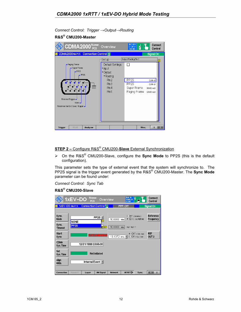
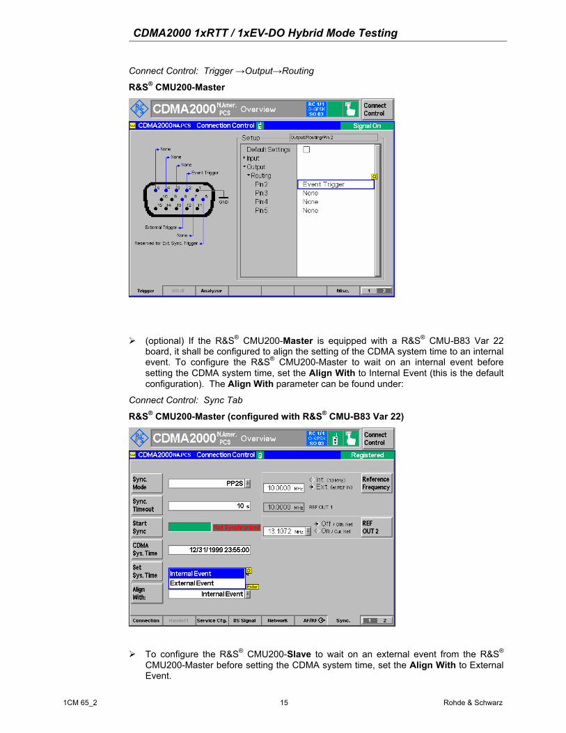
STEP 1 – Configure R&S® CMU200-Master output trigger signal
On the R&S® CMU200-Master, configure the output trigger signal on PIN 2 to be PP2S. The output trigger signal for PIN 2 setting can be found at
CDMA2000 1xRTT / 1xEV-DO Hybrid Mode Testing
1CM 65_2 12 Rohde & Schwarz
Connect Control: Trigger →Output→Routing
R&S® CMU200-Master
STEP 2 – Configure R&S® CMU200-Slave External Synchronization
On the R&S® CMU200-Slave, configure the Sync Mode to PP2S (this is the default configuration).
This parameter sets the type of external event that the system will synchronize to. The PP2S signal is the trigger event generated by the R&S® CMU200-Master. The Sync Mode parameter can be found under:
Connect Control: Sync Tab
R&S® CMU200-Slave

CDMA2000 1xRTT / 1xEV-DO Hybrid Mode Testing
1CM 65_2 13 Rohde & Schwarz
On the R&S® CMU200-Slave, configure the Sync Timeout to be 10 seconds (this is the default configuration).
This parameter sets the amount of time the system will wait for the external synchronization event. The Sync Timeout parameter can be found under:
Connect Control: Sync Tab
R&S® CMU200-Slave
STEP 3 – Synchronize periodic trigger pulse with a 2 second period (PP2S)
Initiate the PP2S synchronization from the R&S® CMU200-Slave.
This procedure triggers a re-synchronization of the timing hardware in the system and can take up to 50 seconds to complete. The Start Sync command button can be found under:
Connect Control: Sync Tab
R&S® CMU200-Slave
CDMA2000 1xRTT / 1xEV-DO Hybrid Mode Testing
1CM 65_2 14 Rohde & Schwarz
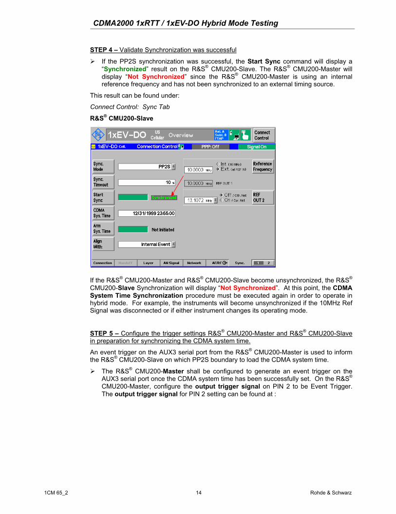
STEP 4 – Validate Synchronization was successful
If the PP2S synchronization was successful, the Start Sync command will display a “Synchronized” result on the R&S® CMU200-Slave. The R&S® CMU200-Master will display “Not Synchronized” since the R&S® CMU200-Master is using an internal reference frequency and has not been synchronized to an external timing source.
This result can be found under:
Connect Control: Sync Tab
R&S® CMU200-Slave
If the R&S® CMU200-Master and R&S® CMU200-Slave become unsynchronized, the R&S® CMU200-Slave Synchronization will display “Not Synchronized”. At this point, the CDMA System Time Synchronization procedure must be executed again in order to operate in hybrid mode. For example, the instruments will become unsynchronized if the 10MHz Ref Signal was disconnected or if either instrument changes its operating mode.
STEP 5 – Configure the trigger settings R&S® CMU200-Master and R&S® CMU200-Slave in preparation for synchronizing the CDMA system time.
An event trigger on the AUX3 serial port from the R&S® CMU200-Master is used to inform the R&S® CMU200-Slave on which PP2S boundary to load the CDMA system time.
The R&S® CMU200-Master shall be configured to generate an event trigger on the AUX3 serial port once the CDMA system time has been successfully set. On the R&S® CMU200-Master, configure the output trigger signal on PIN 2 to be Event Trigger. The output trigger signal for PIN 2 setting can be found at :
CDMA2000 1xRTT / 1xEV-DO Hybrid Mode Testing
1CM 65_2 15 Rohde & Schwarz
Connect Control: Trigger →Output→Routing
R&S® CMU200-Master
(optional) If the R&S® CMU200-Master is equipped with a R&S® CMU-B83 Var 22 board, it shall be configured to align the setting of the CDMA system time to an internal event. To configure the R&S® CMU200-Master to wait on an internal event before setting the CDMA system time, set the Align With to Internal Event (this is the default configuration). The Align With parameter can be found under:
Connect Control: Sync Tab
R&S® CMU200-Master (configured with R&S® CMU-B83 Var 22)
To configure the R&S® CMU200-Slave to wait on an external event from the R&S® CMU200-Master before setting the CDMA system time, set the Align With to External Event.

CDMA2000 1xRTT / 1xEV-DO Hybrid Mode Testing
1CM 65_2 16 Rohde & Schwarz
The R&S® CMU200-Slave shall be configured to wait for an external trigger event from the R&S® CMU200-Master before setting the CDMA system time. Once the external trigger event is detected, the R&S® CMU200-Slave will set the CDMA system time on the next PP2S signal. The Align With parameter can be found under:
Connect Control: Sync Tab
R&S® CMU200-Slave
STEP 6 – Preload the CDMA system time on the R&S® CMU200-Master and the R&S® CMU200-Slave
The first step in synchronizing the CDMA system time is to pre-load the R&S® CMU200-Master and R&S® CMU200-Slave instruments with the same CDMA system time. The time string must be entered in a special date/time format "mm/dd/yyyy HH:MM:SS" and should have an even second value.
To pre-load the CDMA system time, configure the CDMA Sys. Time parameter and hit ENTER. Do this on both instruments.
The CDMA Sys. Time parameter can be found under:

CDMA2000 1xRTT / 1xEV-DO Hybrid Mode Testing
1CM 65_2 17 Rohde & Schwarz
Connect Control: Sync Tab
R&S® CMU200-Slave
STEP 7 – Arm the CDMA system time on the R&S® CMU200-Slave
Once the CDMA system time is pre-loaded on both instruments, the R&S® CMU200-Slave is armed to wait for the external event from the R&S® CMU200-Master to complete its setting of the CDMA system time.
The next step, STEP 8, must occur within 30 seconds after arming the CDMA system time on the R&S® CMU200-Slave
The R&S® CMU200-Slave can be armed by executing the Arm Sys Time action.
Once the R&S® CMU200-Slave is armed, the Arm Sys. Time parameter will transition from “Not Initiated” to the “In Progress…” state. The Arm Sys. Time action can be found under:
Connect Control: Sync Tab
R&S® CMU200-Slave
CDMA2000 1xRTT / 1xEV-DO Hybrid Mode Testing
1CM 65_2 18 Rohde & Schwarz
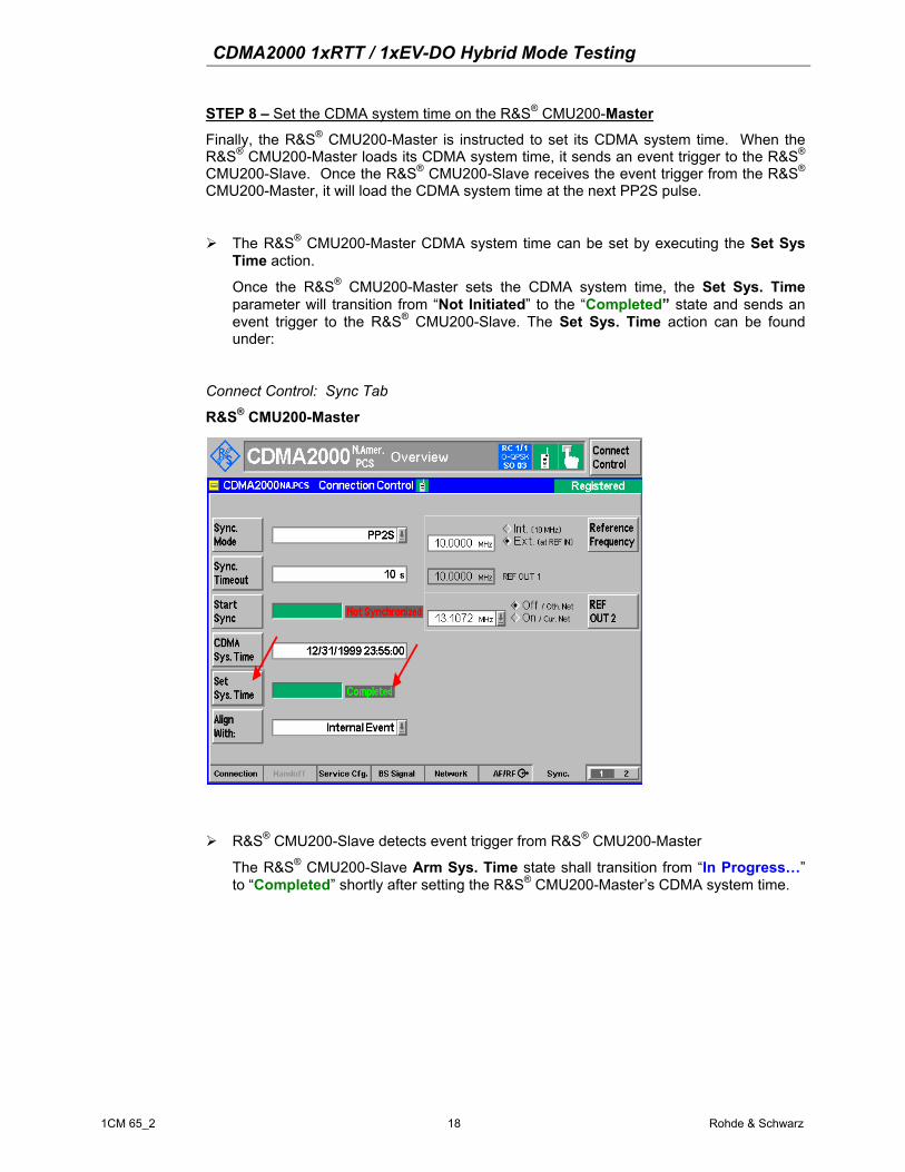
STEP 8 – Set the CDMA system time on the R&S® CMU200-Master
Finally, the R&S® CMU200-Master is instructed to set its CDMA system time. When the R&S® CMU200-Master loads its CDMA system time, it sends an event trigger to the R&S® CMU200-Slave. Once the R&S® CMU200-Slave receives the event trigger from the R&S® CMU200-Master, it will load the CDMA system time at the next PP2S pulse.
The R&S® CMU200-Master CDMA system time can be set by executing the Set Sys Time action.
Once the R&S® CMU200-Master sets the CDMA system time, the Set Sys. Time parameter will transition from “Not Initiated” to the “Completed” state and sends an event trigger to the R&S® CMU200-Slave. The Set Sys. Time action can be found under:
Connect Control: Sync Tab
R&S® CMU200-Master
R&S® CMU200-Slave detects event trigger from R&S® CMU200-Master
The R&S® CMU200-Slave Arm Sys. Time state shall transition from “In Progress…” to “Completed” shortly after setting the R&S® CMU200-Master’s CDMA system time.

CDMA2000 1xRTT / 1xEV-DO Hybrid Mode Testing
1CM 65_2 19 Rohde & Schwarz
R&S® CMU200-Slave
R&S® CMU200-Master
The CDMA system time on both the R&S® CMU200-Master and R&S® CMU200-Slave instruments are now aligned. At this point, the user shall configure the Network / BS signal to match the mobile’s configuration (ie, System Id, Network Id, RF channel, RF band class).
NOTE: If the R&S® CMU200-Master and R&S® CMU200-Slave become unsynchronized, the R&S® CMU200-Slave Synchronization will display “Not Synchronized”. At this point, the CDMA System Time Synchronization procedure must be executed again in order to operate in hybrid mode.
The instruments will become unsynchronized, for example, if any of the following occur:
CDMA2000 1xRTT / 1xEV-DO Hybrid Mode Testing
1CM 65_2 20 Rohde & Schwarz
• 10MHz Ref Signal is disconnected
• Either instrument changes its operating mode.
Changing the operating mode includes switching between non-signaling and signaling or changing different RF bands (CDMA2000 450, CDMA2000 Cellular, CDMA2000 PCS, CDMA2000 IMT2000) in CDMA2000 1xRTT.

CDMA2000 1xRTT / 1xEV-DO Hybrid Mode Testing
1CM 65_2 21 Rohde & Schwarz
5 Access Terminal Hybrid Mode Configuration The mobile must be configured to operate in a hybrid mode environment. The following steps describe the configuration necessary on the mobile.
STEP 1 – Configure Mobile with Hybrid Preferred Roaming List (PRL)
The PRL can be loaded onto most mobiles using the diagnostic interface. The PRL must include defined associations (see Assn Incl, Assn Tag) between IS-2000 and IS-856 systems. The PRL in Figure 5 is an example of a hybrid PRL containing CDMA2000 1xEV-DO channels PCS 150, USC 150 and CDMA2000 1xRTT channels PCS 250, USC 200.
Figure 5. Example Hybrid Mode Preferred Roaming List
STEP 2 – Configure the Mobile’s Hybrid Preference
The hybrid preference specifies whether or not a mobile is to perform dual system operation. The hybrid preference can be set through the user interface and must be set to “Enabled”.
STEP 3 – Configure the Mobile’s Hybrid Operation
The hybrid operation defines which systems are being served. The hybrid operation can be set through the user interface and must be set to CDMA+HDR.
STEP 4 – Configure the Mobile’s Speech Call Service Preference
The DDTM parameter defines the preference for handling incoming speech calls while in a packet data connection (OFF = accept speech call; ON = send speech call directly to voice mail)

CDMA2000 1xRTT / 1xEV-DO Hybrid Mode Testing
1CM 65_2 22 Rohde & Schwarz
6 CDMA2000 Hybrid Mode Tests For more details on hybrid mode test cases, see [3].
Voice Call Termination during 1xEV-DO Data Call This test (see [3]; section 4.2.2) verifies that the mobile is able to accept incoming speech calls from the CDMA2000 1xRTT system while in a CDMA2000 1xEV-DO data call. The mobile should accept the incoming speech call (DDTM=OFF) and transition the packet data connection to PPP dormant. This test can be executed while the CDMA2000 1xEV-DO data call is PPP Connected or PPP Dormant. The steps outlined below cover the scenario while the CDMA2000 1xEV-DO data call is PPP Connected.
STEP 1 – Acquire CDMA2000 1xRTT and CDMA2000 1xEV-DO service
Allow the mobile to register on the CDMA2000 1xRTT system and open a default packet application session on the CDMA2000 1xEV-DO network. For details on opening a default packet application session, see the CDMA2000 1xEV-DO Packet Data Testing Application Note [2].
STEP 2 – Establish a CDMA2000 1xEV-DO Data Call and Tx/Rx data
The CDMA2000 1xEV-DO Data Testing Application Note [2] and CMU200 Operating Manual [1] explain the procedure for setting up a packet data call in detail.
Once the packet data connection is opened the state of the CDMA2000 1xEV-DO data call should indicate PPP Connected.
R&S® CMU200-Slave
STEP 3 – Send a CDMA2000 1xRTT Page with service option 3 (Speech Service)
From the R&S® CMU200-Master, attempt to connect a speech service call while packet data is being transmitted and received. The mobile should be tuning to the CDMA2000 1xRTT system during its paging slots to listen for paging messages containing its IMSI_S. Once the page is recognized by the mobile, the user will be prompted to answer or reject the incoming voice call. When the Page Response message is sent back to the

CDMA2000 1xRTT / 1xEV-DO Hybrid Mode Testing
1CM 65_2 23 Rohde & Schwarz
CDMA2000 1xRTT system, the CDMA2000 1xEV-DO data call will transition to PPP dormant and the speech service call will commence.
NOTE: Other service options may be used in this step (loopback, test data service option, etc).
R&S® CMU200-Slave
STEP 4 – End the speech service call
After the speech service call is released, verify that the mobile re-connects the CDMA2000 1xEV-DO data call and transitions back to PPP Connected.
Voice Call Origination during 1xEV-DO Data Call This test verifies that the mobile is able to initiate speech calls on the CDMA2000 1xRTT system while in a CDMA2000 1xEV-DO data call. The mobile should be able to initiate a speech call and transition the packet data connection from PPP connected to PPP dormant. This test can be executed while the CDMA2000 1xEV-DO data call is PPP Connected or PPP Dormant. The steps outlined below cover the scenario while the CDMA2000 1xEV-DO data call is PPP Connected.
STEP 1 – Acquire CDMA2000 1xRTT and CDMA2000 1xEV-DO service
Allow the mobile to register on the CDMA2000 1xRTT system and open a default packet application session on the CDMA2000 1xEV-DO network. For details on opening a default packet application session, see the CDMA2000 1xEV-DO Packet Data Testing Application Note [2].
STEP 2 – Establish a CDMA2000 1xEV-DO Data Call and Tx/Rx data
The CDMA2000 1xEV-DO Packet Data Testing Application Note [2] and CMU200 Operating Manual [1] explain the procedure for setting up a packet data call in detail.
Once the packet data connection is opened the state of the CDMA2000 1xEV-DO data call should indicate PPP Connected.

CDMA2000 1xRTT / 1xEV-DO Hybrid Mode Testing
1CM 65_2 24 Rohde & Schwarz
STEP 3 – Initiate a speech service call from the mobile
While packet data is being Tx/Rx, attempt a voice service call from the mobile and verify that the call completes and the CDMA2000 1xEV-DO data call transitions to PPP Dormant.
STEP 4 – End the speech service call
After releasing the speech service call, verify that the mobile re-connects the CDMA2000 1xEV-DO data call and transitions back to PPP Connected.
SMS during 1xEV-DO Data Call This test verifies that the mobile is able to accept incoming SMS messages from the CDMA2000 1xRTT system while in a CDMA2000 1xEV-DO data call.
STEP 1 – Acquire CDMA2000 1xRTT and CDMA2000 1xEV-DO service
See Step 1 in “CDMA2000 1xRTT Speech Service Call during CDMA2000 1xEV-DO Data Call” section.
STEP 2 – Establish a CDMA2000 1xEV-DO Data Call and Tx/Rx data
See Step 2 in “CDMA2000 1xRTT Speech Service Call during CDMA2000 1xEV-DO Data Call” section.
STEP 3 – Send a SMS message from CDMA2000 1xRTT system
From the R&S® CMU200-Master, send a Wireless Messaging Teleservice (WMT) SMS message. The mobile should be tuning to the CDMA2000 1xRTT system during its paging slots to listen for paging messages containing its IMSI_S. Once the page is recognized by the mobile, the page response is sent back to the CDMA2000 1xRTT system and the SMS data burst messages are received and optionally acknowledged by the mobile. After receiving the SMS message, the mobile resumes the CDMA2000 1xEV-DO data connection.

CDMA2000 1xRTT / 1xEV-DO Hybrid Mode Testing
1CM 65_2 25 Rohde & Schwarz
Intra-PDSN Active Data Handoff from 1xEV-DO to 1xRTT This test verifies that the mobile is able to handoff an active data session from a CDMA2000 1xEV-DO base station to a CDMA2000 1xRTT base station in a hybrid mode environment. For this test case, both the CDMA2000 1xEV-DO base station and CDMA2000 1xRTT base station are controlled by a single PDSN Server. The R&S® CMU200 has the ability to operate as a PDSN Server or a PDSN Client. In the PDSN Server mode, the R&S® CMU200 performs the PDSN functionality - establishes a PPP connection with the mobile and controls where the IP packets are routed. See Figure 6.
BSC
PCF
BTS
BSC
PCF
BTS
PDSN
1xRTT
1xEV-DO
Figure 6. Intra-PDSN Active Data Handoff

CDMA2000 1xRTT / 1xEV-DO Hybrid Mode Testing
1CM 65_2 26 Rohde & Schwarz
Mobile Connected to PDSN Server - IP Packet Flow
If the mobile has a traffic channel assigned on the R&S® CMU200 configured as the PDSN Server, then the IP packets transmitted/received to/from the mobile will be sent directly via the RF interface. See Figure 7.
R&S® CMU200 – 1xEV-DO R&S® CMU200 – 1xRTT
PDSN Server PDSN Client
WWW ServerFTP Server
Video Streaming Server
etc
Ethernet
Mobile Terminated Packet Data Path
Mobile Originated Packet Data Path
Figure 7. Traffic Channel assigned on PDSN Server - IP Packet Data Path

CDMA2000 1xRTT / 1xEV-DO Hybrid Mode Testing
1CM 65_2 27 Rohde & Schwarz
Mobile Connected to PDSN Client - IP Packet Flow
If the mobile has a traffic channel assigned on the R&S® CMU200 configured as the PDSN Client, then the mobile's PPP connection will terminate at the R&S® CMU200 configured as the PDSN Server which will route the PPP packets destined for the mobile to the Ethernet interface of the R&S® CMU200 configured as the PDSN Client (using PPP over Ethernet) . The PDSN Client will then route the PPP data to the mobile via the RF Interface. See Figure 8.
R&S® CMU200 – 1xEV-DO R&S® CMU200 – 1xRTT
PDSN Server PDSN Client
WWW ServerFTP Server
Video Streaming Serveretc
Ethernet
Mobile Terminate Packet Data Path
Figure 8. Traffic Channel assigned on PDSN Client - IP Packet Data Path

CDMA2000 1xRTT / 1xEV-DO Hybrid Mode Testing
1CM 65_2 28 Rohde & Schwarz
STEP 1 – Synchronize R&S® CMU200 1xEV-DO and R&S® CMU200 1xRTT systems
See Section 4 above. Configure the R&S® CMU200 1xEV-DO system as the Master and the R&S® CMU200 1xRTT system as the Slave. Connect a remote data application server to the test environment (optional). See Figure 9.
R&S® CMU200 – 1xRTT (Slave)
PDSN Server PDSN Client
(Optional)WWW ServerFTP Server
Video Streaming Server
etc
Ethernet
R&S® CMU200 – 1xEV-DO (Master)
Figure 9. Hybrid Mode Active Data Session Test Setup
STEP 2 – Configure R&S® CMU200 1xEV-DO (Master) as the PDSN Server
There is no restriction on where the PDSN Server resides, but for simplicity, configure the PDSN Server on the R&S® CMU200 designated as the Master.
To configure the R&S® CMU200 as the PDSN Server, set the PDSN Mode to Server and configure the PDSN Client IP Address and PDSN Server/Client Ports (the default port settings can also be used). The PDSN Client IP Address is equal to the IP Address assigned to the R&S® CMU200 1xRTT B83 board. The PDSN Client Port is equal to the PDSN Client Port defined on the R&S® CMU200 1xRTT machine. The IP Address of the PDSN Server is the same IP Address used for the R&S® CMU200 B83 board (defined under SETUP->TCP/IP).

CDMA2000 1xRTT / 1xEV-DO Hybrid Mode Testing
1CM 65_2 29 Rohde & Schwarz
The PDSN Mode, PDSN Client IP Address & Port parameters can be found under:
Connect Control: Layer Tab->Application->Packet Application
R&S® CMU200-Master
STEP 3 – Configure R&S® CMU200 1xRTT (Slave) as the PDSN Client
To configure the R&S® CMU200 as the PDSN Client, set the PDSN Mode to Client and configure the PDSN Server IP Address and PDSN Server/Client Ports. The PDSN Server IP Address is equal to the IP Address assigned to the R&S® CMU200 1xEV-DO B83 board. The PDSN Server Port is equal to the PDSN Server Port defined on the R&S® CMU200 1xEV-DO machine. The IP Address of the PDSN Client is the same IP Address used for the R&S® CMU200 B83 board (defined under SETUP->TCP/IP).
The PDSN Mode, PDSN Server IP Address & Port parameters can be found under:
Connect Control: ServiceCfg Tab->Packet Data Service->SO33->Protocol

CDMA2000 1xRTT / 1xEV-DO Hybrid Mode Testing
1CM 65_2 30 Rohde & Schwarz
R&S® CMU200-Slave
STEP 4 – Acquire CDMA2000 1xRTT and CDMA2000 1xEV-DO service
See Step 1 in “CDMA2000 1xRTT Speech Service Call during CDMA2000 1xEV-DO Data Call” section.
STEP 5 – Establish a CDMA2000 1xEV-DO Data Call and Tx/Rx data
See Step 2 in “CDMA2000 1xRTT Speech Service Call during CDMA2000 1xEV-DO Data Call” section. NOTE: The PPP and Mobile IP Addressing must be configured on the R&S® CMU200 which is designated as the PDSN Server.
STEP 6 – Trigger Active Data handoff from CDMA2000 1xEV-DO to CDMA2000 1xRTT
In order to trigger an active data handoff from CDMA2000 1xEV-DO to CDMA2000 1xRTT, the user can simulate the AT moving out of the hybrid coverage area by degrading the CDMA2000 1xEV-DO signal. Once the AT recognizes the loss of the hybrid coverage area, the mobile shall attempt to hand-down the active data session from CDMA2000 1xEV-DO to CDMA2000 1xRTT. The mobile will attempt to establish a SO33 data call on the CDMA2000 1xRTT system and continue the data transfer. The same PPP connection will be maintained.
CDMA2000 1xRTT / 1xEV-DO Hybrid Mode Testing
1CM 65_2 31 Rohde & Schwarz
Examples of Additional Supported Hybrid Test Scenarios
• Active data session handoff from a CDMA2000 1xRTT system to a CDMA2000 1xEVDO system
• Origination / Termination of a voice call while in an Active CDMA2000 1xEVDO data session
• Origination / Termination of a voice call while in a Dormant CDMA2000 1xEVDO data session
• Origination / Termination of a SMS message while in an Active CDMA2000 1xEVDO data session
• Origination / Termination of a SMS message while in a Dormant CDMA2000 1xEVDO data session
• Open a Session with CDMA2000 1xEVDO system and Register with the CDMA2000 1xRTT system

CDMA2000 1xRTT / 1xEV-DO Hybrid Mode Testing
1CM 65_2 32 Rohde & Schwarz
7 References [1] 1xEV-DO for R&S® CMU-B88/-B89 Operating Manual; Rohde and Schwarz
[2] CDMA2000 1xEV-DO Packet Data Testing Application Note; Rohde and Schwarz; 1_CM64_01
[3] 3GPP2 A.S0008-B Version 1.0; Inter-Operability Specification for High Rate Packet Data Radio Access Network Interfaces with Session Control in the Access Network
8 R&S® CMU200 Ordering Information R&S® CMU200 Universal Radio Communications Tester
R&S® CMU-B83 Var 22 New CDMA2000 signalling unit (ready for CMU-B89)
R&S® CMU-U83 Var 22 CDMA2000 signalling unit, upgrade from CMU-B83 Var 12
R&S® CMU-B85 Var 22 Speech Coder for 8K BASIC, 8K EVRC, 13K (CMU-B83 Var 22)
R&S® CMU-U85 Var 22 Speech Coder for 8K BASIC, 8K EVRC, 13K (CMU-B83 Var 22) upgrade from CMU-B85 Var 12
R&S® CMU-K839 1xEV-DO, 450MHz (Band Class 5, 11)
R&S® CMU-K849 1xEV-DO, Cellular band (Band Class 0, 2, 3, 7, 9, 10, 12)
R&S® CMU-K859 1xEV-DO, PCS band (Band Class 1, 4, 8, 14)
R&S® CMU-K869 1xEV-DO, IMT band (Band Class 6, 13, 15, 16, 17)
R&S® CMU-PK800 SW Package for 1xEV-DO
R&S® CMU-U65 3G Measurement DSP module
R&S® CMU-B89 1xEV-DO Signaling Module (for CMU-B83 Var 22)
R&S® CMU-B87 Interface for CDMA2000 1xRTT / 1xEV-DO Data Testing
R&S® CMU-K87 CDMA2000 1xRTT / 1xEV-DO Data Testing
R&S® CMU-Z89 Hybrid Mode Test Kit

CDMA2000 1xRTT / 1xEV-DO Hybrid Mode Testing
1CM 65_2 33 Rohde & Schwarz
9 Appendix A – Quick How To This table provides a quick how-to for configuring the R&S® CMU200 in a hybrid mode test environment.

CDMA2000 1xRTT / 1xEV-DO Hybrid Mode Testing
1CM 65_2 34 Rohde & Schwarz
10 Appendix B – GPIB Sequence The following example program illustrates how to configure two CMU200s in a hybrid mode environment. In the example, remote control via GPIB bus (daisy-chained together) and the programming language Winbatch is used. Before running the program, configure your Winbatch settings such that C2KPCS_Sig-M, CMUBASE-M are the device names used on the Master CMU200 and CMUBASE-S, EVDO_Sig-S are the device names for the Slave CMU200. [IEEE Device 1] Name=CMUBASE-M Board Index=0 Primary Address=20 Secondary Address=96 EOI Mode=1 EOS Character=0 Timeout=300 Reading Method=2 [IEEE Device 2] Name=CMUBASE-S Board Index=0 Primary Address=21 Secondary Address=96 EOI Mode=1 EOS Character=0 Timeout=60 Reading Method=1 [IEEE Device 3] Name=C2KPCS_Sig-M Board Index=0 Primary Address=20 Secondary Address=97 EOI Mode=1 EOS Character=0 Timeout=10 Reading Method=2 [IEEE Device 4] Name=EVDO_Sig-S Board Index=0 Primary Address=21 Secondary Address=97 EOI Mode=1 EOS Character=0 Timeout=30 Reading Method=2

CDMA2000 1xRTT / 1xEV-DO Hybrid Mode Testing
1CM 65_2 35 Rohde & Schwarz
ECHO ON
FPRINT ---------------------------------------------------------------------
FPRINT Hybrid Mode Setup GPIB Script Example
FPRINT Master - CDMA2000 1xRTT PCS
FPRINT Slave - CDMA2000 1xEVDO
FPRINT ---------------------------------------------------------------------
; Reset the Master and configure it for CDMA 1xRTT PCS
CMUBASE-M: *IDN?
CMUBASE-M: *RST;*OPC?
CMUBASE-M: *CLS
CMUBASE-M: TRAC:REM:MODE:DISP ON
CMUBASE-M: SYST:REM:ADDR:SEC 1,"CDMA2KPCSMS_Sig"
; Reset the Slave and configure it for 1xEVDO
CMUBASE-S: *IDN?
CMUBASE-S: *RST;*OPC?
CMUBASE-S: *CLS
CMUBASE-S: TRAC:REM:MODE:DISP ON
CMUBASE-S: SYST:REM:ADDR:SEC 1,"EVDO1XAT_Sig"
; Set the Master Reference Frequency to Internal
CMUBASE-M: CONF:SYNC:FREQ:REF:MODE INT
; Set the Slave Reference Frequency to External
CMUBASE-S: CONF:SYNC:FREQ:REF:MODE EXT
; Ready for test
; Turn the signal on
C2KPCS_Sig-M: 1; PROC:SIGN:ACT SON;*OPC?
EVDO_Sig-S: 1; PROC:SIGN:ACT SON;*OPC?
; Set the Master Output Trigger:PIN2 to PP2S
C2KPCS_Sig-M: 1;TRIGger:OUTPut:PIN2:SIGNal PP2S; *OPC?
; Set the Slave Ext Sync Mode to PP2S
EVDO_Sig-S: 1;CONF:ESYN:MODE PP2S; *OPC?
; Set the Slave Sync Timeout to 20 sec
EVDO_Sig-S: 1;CONF:ESYN:TOUT 20; *OPC?

CDMA2000 1xRTT / 1xEV-DO Hybrid Mode Testing
1CM 65_2 36 Rohde & Schwarz
FPRINT ---------------------------------------------------------------------
FPRINT Starting PP2S synchronization
FPRINT ---------------------------------------------------------------------
; Press Start Sync and Wait for Success
EVDO_Sig-S: 1;INIT:ESYN
; Wait for Sync to complete
REPORT OFF
[Wait_Sync]
IF EVDO_Sig-S: 1; ESYN:STAT? = EXT GOTO Sync_OK
PAUSE 100
GOTO Wait_Sync
[Sync_OK]
FPRINT ---------------------------------------------------------------------
FPRINT PP2S synchronization complete
FPRINT ---------------------------------------------------------------------
; Set the Master Output Trigger:PIN2 to Event Trigger
C2KPCS_Sig-M: 1; TRIGger:OUTPut:PIN2:SIGNal ETR; *OPC?
; Set the Master/Slave CDMA System Time
C2KPCS_Sig-M: 1;CONF:ESYN:SYST:TIME "10/31/2004 17:00:00"
EVDO_Sig-S: 1; CONF:ESYN:SYST:TIME "10/31/2004 17:00:00"
; Set the Master CDMA System time to align with Internal Event
C2KPCS_Sig-M: 1; CONF:ESYN:ALIG INT
; Set the Slave CDMA System time to align with External Event
EVDO_Sig-S: 1; CONF:ESYN:ALIG EXT
PAUSE 1000
FPRINT ---------------------------------------------------------------------
FPRINT ARM the CDMA System time on the Slave
FPRINT ---------------------------------------------------------------------
; Arm the Slave CDMA System Time
EVDO_Sig-S: 1; INIT:ESYN:SYST:TIME

CDMA2000 1xRTT / 1xEV-DO Hybrid Mode Testing
1CM 65_2 37 Rohde & Schwarz
FPRINT ---------------------------------------------------------------------
FPRINT Set the CDMA System time on the Master
FPRINT ---------------------------------------------------------------------
; Set the Master CDMA System Time
C2KPCS_Sig-M: 1; INIT:ESYN:SYST:TIME
FPRINT ---------------------------------------------------------------------
FPRINT Waiting for Setting of CDMA System Time to complete
FPRINT ---------------------------------------------------------------------
REPORT OFF
; Wait for time to complete
[Wait_Time]
IF EVDO_Sig-S: 1; ESYN:SYST:TIME:STAT? = RDY GOTO Time_OK
PAUSE 3000
GOTO Wait_Time
[Time_OK]
REPORT ON
FPRINT ---------------------------------------------------------------------
FPRINT (Optional) Add Ethernet connection between Master and Slave instruments
FPRINT ---------------------------------------------------------------------
FPRINT ---------------------------------------------------------------------
FPRINT Hybrid Mode Setup Complete
FPRINT ---------------------------------------------------------------------

CDMA2000 1xRTT / 1xEV-DO Hybrid Mode Testing
1CM 65_2 38 Rohde & Schwarz
1 CDMA2000® is a registered trademark of the Telecommunications Industry Association (TIA -USA)