cdma-based dcp communications systemnoaasis.noaa.gov/dcs/docs/dcpr_cdma.pdf• cdma-only system is a...
TRANSCRIPT

15/12/2004
MIT Lincoln Laboratory
CDMA-Based DCP Communications System
Ryan Shoup, John Taylor, Bob Wezalis

MIT Lincoln Laboratory25/12/2004
DCP CDMA-Overlay Overview
• CDMA overview• CDMA-overlay concept
– Overview– Capacity results
• CDMA-only concept– Overview– Capacity results
• Considerations in applying CDMA to DCS• Summary

MIT Lincoln Laboratory35/12/2004
CDMA Overview
• CDMA users transmit spread spectrum signal at the same time using all of the available bandwidth
– Each user assigned a unique code so that the receiver can separate out a particular user’s signal
– Codes have low cross correlation for separation• Wideband signals interfere with each other
• Managed Resource– Power compared to frequency (FDMA) or time (TDMA)– CDMA capacity maximized when the SINRs of the users are all equal and
minimum for a desired BER• “Soft degradation” with increasing number of users
– CDMA: Supported based on tolerable amount of interference• If BER of 10-5 is acceptable compared to 10-6 → Capacity increase
• CDMA Presence – Terrestrial cellular migrating to CDMA (IS95 → IS2000 , GSM → WCDMA)– Conceptual design for Globalstar based on CDMA

MIT Lincoln Laboratory45/12/2004
CDMA Overview (con’t)
• Asynchronous CDMA vs Synchronous CDMA– Synchronous requires signals be aligned in time but better capacity
• Signal alignment is at the chip level: Clocks need to be accurate on microsecond scale, path delays need to be known to the microsecond level, etc.
• Cellular uses synchronous on the links from base station to mobile (1→many) channel
– Asynchronous does not require signals to be aligned in time but worse capacity• Cellular uses asynchronous on the links from mobile to base station (many→1)
channel• Spreading Sequences or “Codes”
– Long random codes • Capacity interference limited (ie: as C/N0 →∞, capacity still finite)• Requires more granular synchronization
– Short codes• Capacity Interference limited• No synchronization required
– Orthogonal codes• Capacity not interference limited• Limited Applicability
MIT Lincoln Laboratory55/12/2004
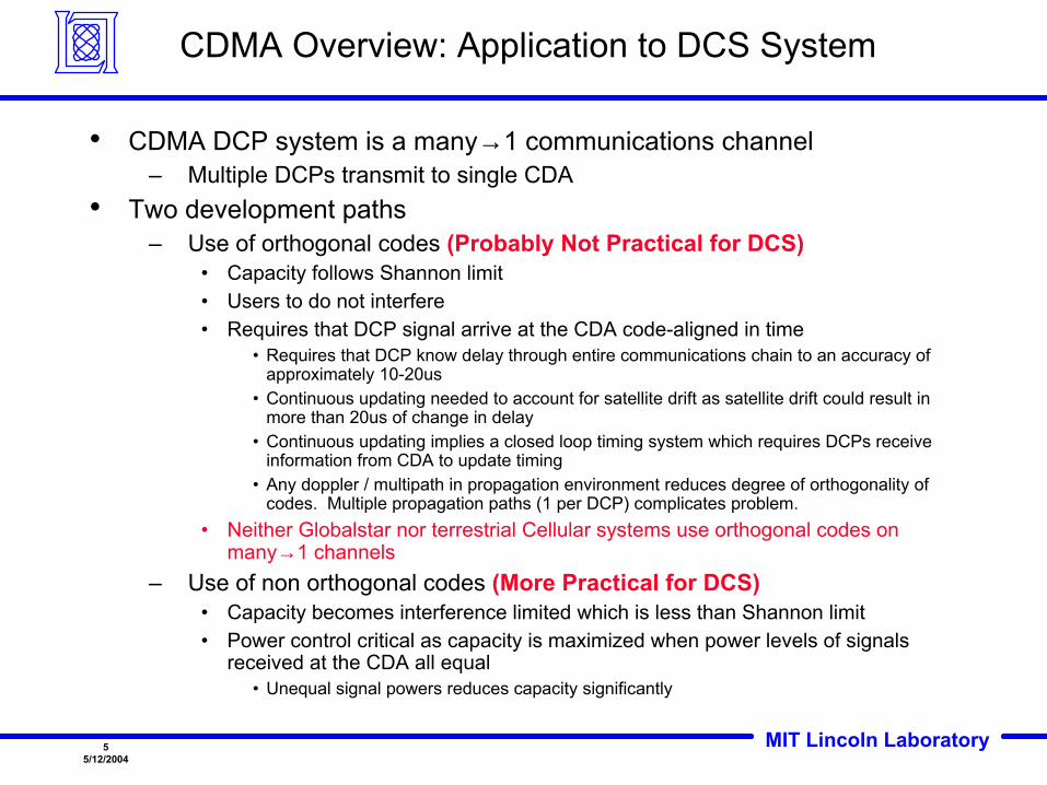
CDMA Overview: Application to DCS System
• CDMA DCP system is a many→1 communications channel– Multiple DCPs transmit to single CDA
• Two development paths– Use of orthogonal codes (Probably Not Practical for DCS)
• Capacity follows Shannon limit• Users to do not interfere• Requires that DCP signal arrive at the CDA code-aligned in time
• Requires that DCP know delay through entire communications chain to an accuracy of approximately 10-20us
• Continuous updating needed to account for satellite drift as satellite drift could result in more than 20us of change in delay
• Continuous updating implies a closed loop timing system which requires DCPs receive information from CDA to update timing
• Any doppler / multipath in propagation environment reduces degree of orthogonality of codes. Multiple propagation paths (1 per DCP) complicates problem.
• Neither Globalstar nor terrestrial Cellular systems use orthogonal codes on many→1 channels
– Use of non orthogonal codes (More Practical for DCS)• Capacity becomes interference limited which is less than Shannon limit• Power control critical as capacity is maximized when power levels of signals
received at the CDA all equal• Unequal signal powers reduces capacity significantly

MIT Lincoln Laboratory65/12/2004
DCP CDMA-Overlay Concept
• Overlay a CDMA-based DCP uplink onto the current 400KHz of spectrum used for the existing DCPR system
• Assign unique random codes to the individual CDMA-overlay DCPs• CDMA-overlay DCPs transmit a 400KHz direct sequence spread spectrum
(DSSS) signal simultaneously– Results in interference to both CDMA and FDMA DCPs– Goal is to ensure interference levels are tolerable for both– Interference well modeled as AWGN
• CDMA Receiver demodulates DSSS signals for each CDMA-based DCP
• Power levels need to be managed– Excessive powers (link margin) for the desired BER results in unnecessary
interference
• Admission control– Optimal (maximize capacity) implementation should be based on current interference
levels

MIT Lincoln Laboratory75/12/2004
DCP CDMA-Overlay Concept
• CDMA-overlay signals coexist with existing FDMA system without any change to system
– Useful to support low frequency unscheduled transmissions such as emergency transmissions
– CDMA-overlay transmitters provided to DCPs that may require emergencytransmissions
– All emergency transmission dissemination sites equipped with CDMA receivers• CDMA-overlay transmitters exist as separate units ( wrt existing FDMA
transmitter)– Share same antenna and possibly PA
• CDMA-overlay receivers exist as separate units– Share same antenna– Possibly share same RF front-end– Baseband signal processing component exists as separate unit

MIT Lincoln Laboratory85/12/2004
400 KHz
Thermal Noisefrequency
Watts
DCS Spectrum
CDMA Overlay
1 CDMA Signal
Less Margin
Existing FDMA Signals
Interference From All CDMA Signals
Existing System400 KHz
Thermal Noisefrequency
Watts
Margin
Existing FDMA Signals

MIT Lincoln Laboratory95/12/2004
Power Control
• Ideal power control would result in all CDMA-overlay receive powers being equal and minimum to support desired BER performance level
• Power control error reduces capacity• Three approaches to power control
– No power control• Receive power differences ~ 6 dB (terrestrial cellular as high as 50 – 75 dB)
• Path loss, channel (rain, ionospheric affects), antenna gain, specification allows for difference in transmit power
– Open loop power control• CDMA-overlay DCPs measure receive power from DCPI link• Transmit power based on measured receive power• Account for path loss differences and channel• Differences in receive power with open loop power control ~ 3 dB
– Closed loop power control• DCPI link used to send up/down commands to CDMA-overlay DCPs• Differences in receive power with open loop power control ~ 2 dB
• Closed loop power control best but most complex to implement

MIT Lincoln Laboratory105/12/2004
0 50 100 150 200 250 300 350 400 450 500-5
0
5
10
15
20
25
Number of CDMA Overlay Users
CDMA Interference Impact to Existing FDMA DCPs
CDMA Signal Reduces Existing FDMA DCP EB/N0
• CDMA overlay capacity is limited by the amount of interference CDMA users will introduce to narrowband FDMA users
• Plot shows how Existing FDMA DCP EB/N0 decreases as a function of overlay users
Existing FDMADCP EB/N0
Illustrates EB/N0 ↓ as CDMA-overlay users ↑

MIT Lincoln Laboratory115/12/2004
0 50 100 150 200 250 300 35010
15
20
25
57
7
7
9
9
9
911
11
11
13
13
13
15
1517
1719
2123
• CDMA-overlay Capacity– Perfect power control– Ideal Receiver
• Assume typical DCPR operating EB/N0 ~ 13-16 dB
• Further minimum EB/N0 ~ 12 dB• Based on empirical DCPR test
results • Number of users ~ 50 to 110
Theoretical CDMA-Overlay Capacity
Operating Region:EB/N0 Received ~ 13-16 dBRequired Minimum EB/N0 ~ 12 dB
Minimum Required Existing FDMA EB/N0
Number of CDMA-overlayUsers
ActualExistingFDMAEB/N0
UsersSupported

MIT Lincoln Laboratory125/12/2004
0 10 20 30 40 50 60 70 80 90 10010
15
20
25
7
9
9
9
11
11
11
13
13
13
15
15
17
17
19
2123
• Non Ideal CDMA-overlay Capacity– CDMA DCPs receive powers
vary by 6 dB• Receive powers neither
equal nor minimum• Number of users ~ 20 to 45
UsersSupported
Operating Region:EB/N0 Received ~ 13-16 dBRequired Minimum EB/N0 ~ 12 dB
Minimum Required Existing FDMA EB/N0
Number of CDMA-overlayUsers
ActualExistingFDMAEB/N0
Practical CDMA-Overlay Capacity

MIT Lincoln Laboratory135/12/2004
CDMA-Only High Level Concept
• Uplink (Link from DCP to CDAS)– New 400 KHz bandwidth frequency assignment– Use CDMA only– Design to support ~ 400-450 simultaneous
channels (300 BPS)• Data and a few control channels
– Asynchronous• User signals not aligned in time
– BPSK data modulation• Downlink (Link from CDAS to DCP)
– New 40 KHz bandwidth frequency assignment– Use CDMA only– Design to support 32 simultaneous channels (300
BPS)• Power control + control channels
– Synchronous– Signals aligned in time– Allows use of orthogonal codes– QPSK data modulation
GOES
CDASDCPs
Bent Pipe
EB/(I0 + N0) = 2 dB

MIT Lincoln Laboratory145/12/2004
CDMA “Pole Capacity”
• Pole capacity: Theoretical maximum number of users
– Pole capacity attained when EB/N0 → ∞
– Curve assumes random codes
• Practical operating range given by “rise over thermal” between 3-10 dB
• Ideal receiver– Impairments due to noise
+ interference only
0 200 400 600 800 1000 1200 14000
5
10
15
20
25
30
CDMA Pole Capacity)dB(
NE
0
B
Operating Region Theoretical maximumnumber of simultaneous users
dB3NI
0
0 =
dB10NI
0
0 =
Users
Rise over thermal

MIT Lincoln Laboratory155/12/2004
0 100 200 300 400 500 600 7000
5
10
15
20
25
30
Number of Users
CDMA Pole Capacity
No Power Control (Error = 6 dB)No Power Control (Error = 4 dB)Open Loop (Error = 3 dB)Closed Loop (Error = 2 dB)Ideal (No Error)
)dB(NE
0
B
Impact of Power Control
• Pole capacity decreases with inability to control power
• Power control error = power received beyond what is necessary to sustain desired BER

MIT Lincoln Laboratory165/12/2004
• Better suited for multipath fading channels– Additional paths “combined” to result in path
diversity– FDMA/TDMA, additional paths not able to be
combined and results in link degradation• Better suited when omni antennas employed• Better suited for cellular networks (terrestrial)
or spot-beam (satellite) applications– Universal frequency reuse: CDMA reuses
same frequencies in adjacent cells (unlike TMDA/FDMA)
– Soft Handoff gains• Resistant to narrowband interference
– CDMA inherently spread spectrum• Inactivity Gain
– Inactivity (such as pauses in speech) can be translated to capacity gain. This is not possible with FDMA and difficult with TDMA.
AC
BD
CDB
TDMA/FDMA
AA
AA
AAA
CDMA
Frequency Reuse Illustration
Why has the Cellular Community adopted CDMA?
Single frequency employedfor multiple cells
Multiple frequencies employedfor multiple cells

MIT Lincoln Laboratory175/12/2004
CDMA Challenges for DCP
• General Purpose COTS COTS Chipset Availability– Want to use commercial chipsets as custom development of chipsets
costly• CDMA signals require much digital/signal processing resulting in
complex ICs• Existing chipsets are commercially available but designed specifically
for IS2000 or WCDMA which probably wouldn’t be appropriate for aDCS CDMA system
• Chip rates different, Chip sets assume maximum difference in path delay between transmitting units < 250 km, etc
• CDMA systems are more complex• Power control• Admission control
• CDMA-only system is a complete redesign/overhaul of existing system
• CDMA-overlay represents additional hardware to CDA and new transmitters for CDMA-overlay DCPs but existing system remains

MIT Lincoln Laboratory185/12/2004
DCS CDMA Summary
• CDMA-only DCS system– Number of simultaneous users comparable to simpler FDMA system– CDMA system significantly more complex and would require essentially a complete
redesign of current DCS system• CDMA-Overlay DCS system
– May be an effective scheme to support a low number of non-scheduled additional messages
• No change to satellite required• No change to operating practices to support ~ 20 CDMA-overlay users• Used for emergency channels, etc.