ccs rules and regulation
TRANSCRIPT
CHINA CLASSIFICATION SOCIETY 2009 AMENDMENTS TO RULES
FOR MATERIALS AND WELDING
1
CHINA CLASSIFICATION SOCIETY
RULES FOR MATERIALS AND WELDING
(Amendments)
2009
CHINA CLASSIFICATION SOCIETY 2009 AMENDMENTS TO RULES
FOR MATERIALS AND WELDING
2
CONTENTS
PART 0 PROVISIONS OF CLASSIFICATION
CHAPTER 2 SCOPE AND CONDITIONS OF CLASSIFICATION
Section 3 CHARACTERS OF CLASSIFICATION AND CLASS NOTATIONS
Section 5 STATUTORY SERVICES
Section 8 AVAILABILITY AND DISCLOSURE OF INFORMATION
Section 9 LIABILITY, DISAGREEMENT AND ARBITRATION
CHAPTER 3 INSPECTIONS OF PRODUCTS
Section 1 GENERAL PROVISIONS
Section 3 DESIGN APPROVAL
Section 4 TYPE APPROVAL
Section 5 WORKS APPROVAL
PART ONE METALLIC MATERIALS
CHAPTER 2 MATERIAL TESTS
Section 8 CRACK TIP OPENING DISPLACEMENT (CTOD) TEST FOR METALLIC MATERIALS
CHAPTER 3 STEEL PLATES, FLAT BARS AND SECTIONS
Section 2 NORMAL STRENGTH HULL STRUCTURAL STEELS
Section 3 HIGH STRENGTH HULL STRUCTURAL STEELS
Section 5 STEELS FOR BOILERS AND PRESSURE VESSELS
Section 8 AUSTENITIC AND DUPLEX STAINLESS STEELS
CHAPTER 4 STEEL PIPES AND TUBES Section 2 SEAMLESS PRESSURE PIPES
Section 4 BOILER AND SUPERHEATER TUBES
Section 6 AUSTENITIC STAINLESS STEEL PRESSURE PIPES
CHAPTER 7 IRON CASTINGS Section 2 GREY IRON CASTINGS
CHAPTER 10 EQUIPMENT Section 2 ANCHOR CHAIN CABLES AND ACCESSORIES
PART TWO NON-METALLIC MATERIALS
CHAPTER 2 PLASTIC MATERIALS Section 2 RAW MATERIALS
CHAPTER 4 PLASTIC PIPES AND FITTINGS
Section 2 MATERIAL, DESIGN, MANUFACTURE AND STRENGTH TEST
CHAPTER 7 FIBER ROPES
Section 2 MARINE FIBER ROPES
PART THREE WELDING
CHAPTER 1 GENERAL
Section 2 TESTING
CHAPTER 2 WELDING CONSUMABLES
Section 4 WIRE-FLUX COMBINATIONS FOR SUBMERGED ARC AUTOMATIC WELDING
Section 5 WIRES AND WIRE-GAS COMBINATIONS FOR SEMI-AUTOMATIC AND AUTOMATIC
CHINA CLASSIFICATION SOCIETY 2009 AMENDMENTS TO RULES
FOR MATERIALS AND WELDING
3
WELDING
Section 8 WELDING CONSUMABLES FOR STAINLESS STEEL
CHAPTER 3 APPROVAL OF WELDING PROCEDURES Section l GENERAL PROVISIONS
Section 2 WELDING PROCEDURE TESTS FOR BUTT WELD JOINTS
CHAPTER 4 QUALIFICATION TESTS OF WELDERS
Section 1 GENERAL PROVISIONS
Section 2 QUALIFICATION TESTS OF WELDERS AND EVALUATION
Section 3 SCOPE OF APPLICATION OF WELDER’S QUALIFICATION
Section 4 UNDERWATER WELDER QUALIFICATION TESTS AND EVALUATION
CHAPTER 7 WELDING OF PRESSURE VESSELS Section 2 PRODUCTION WELDING TESTS OF PRESSURE SHELLS
Section 3 MANUFACTURE AND WORKMANSHIP OF PRESSURE SHELLS
Section 4 HEAT TREATMENT
Section 5 INSPECTIONS AND REPAIRING
CHAPTER 9 WELDING OF PRESSURE PIPES Section 1 GENERAL PROVISIONS
Section 2 WELDING OF PIPE JOINTS
Section 3 INSPECTION OF WELDING QUALITY
Section 4 HEAT TREATMENT
CHINA CLASSIFICATION SOCIETY 2009 AMENDMENTS TO RULES
FOR MATERIALS AND WELDING
1/40
PART 0 PROVISIONS OF CLASSIFICATION
CHAPTER 2 SCOPE AND CONDITIONS OF CLASSIFICATION
Section 3 CHARACTERS OF CLASSIFICATION AND CLASS NOTATIONS
A new sentence is added at the end of paragraph 2.3.2.1 as follows:
“Class notations may be divided into necessary notations and optional ones.”
In paragraph 2.3.2.2, the word “non-mandatory” is replaced by “optional”.
Section 5 STATUTORY SERVICES
A new paragraph 2.5.2.4 is added as follows:
“2.5.2.4 Where the Administration of the flag State does not have its own special requirements with
regard to the conventions referred to in paragraph 2.5.2.1, the statutory requirements for convention ships
are to include those contained in the Guidelines for Implementation of Statutory Surveys for Ships Engaged
on International Voyages1.”
Section 8 AVAILABILITY AND DISCLOSURE OF INFORMATION
Subparagraph 2.8.2.1(2) is replaced by the following:
“(2) as required by IACS, the updated data related to the Register of Ships, the data of class suspension and
survey status, and the information on failure incidents of ships are to be communicated to IACS;”.
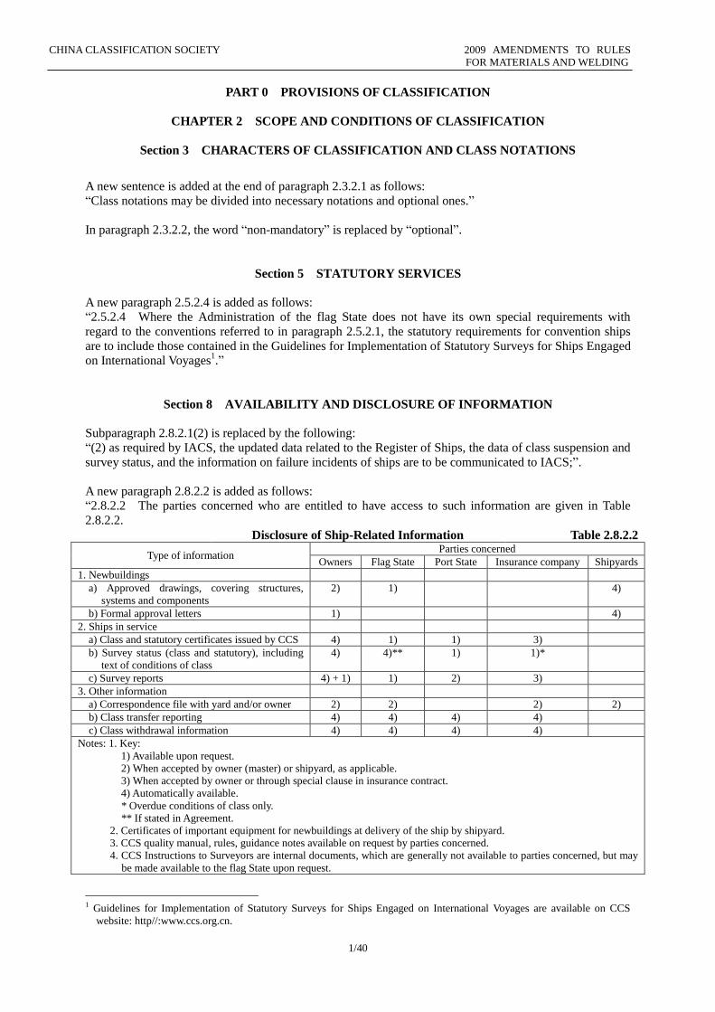
A new paragraph 2.8.2.2 is added as follows:
“2.8.2.2 The parties concerned who are entitled to have access to such information are given in Table
2.8.2.2. Disclosure of Ship-Related Information Table 2.8.2.2
Type of information Parties concerned
Owners Flag State Port State Insurance company Shipyards
1. Newbuildings
a) Approved drawings, covering structures,
systems and components
2) 1) 4)
b) Formal approval letters 1) 4)
2. Ships in service
a) Class and statutory certificates issued by CCS 4) 1) 1) 3)
b) Survey status (class and statutory), including
text of conditions of class
4) 4)** 1) 1)*
c) Survey reports 4) + 1) 1) 2) 3)
3. Other information
a) Correspondence file with yard and/or owner 2) 2) 2) 2)
b) Class transfer reporting 4) 4) 4) 4)
c) Class withdrawal information 4) 4) 4) 4)
Notes: 1. Key:
1) Available upon request.
2) When accepted by owner (master) or shipyard, as applicable.
3) When accepted by owner or through special clause in insurance contract.
4) Automatically available.
* Overdue conditions of class only.
** If stated in Agreement.
2. Certificates of important equipment for newbuildings at delivery of the ship by shipyard.
3. CCS quality manual, rules, guidance notes available on request by parties concerned.
4. CCS Instructions to Surveyors are internal documents, which are generally not available to parties concerned, but may
be made available to the flag State upon request.
1 Guidelines for Implementation of Statutory Surveys for Ships Engaged on International Voyages are available on CCS
website: http//:www.ccs.org.cn.
CHINA CLASSIFICATION SOCIETY 2009 AMENDMENTS TO RULES
FOR MATERIALS AND WELDING
2/40
”
A new paragraph 2.8.2.3 is added as follows:
“2.8.2.3 Notwithstanding the general duty of confidentiality owed by CCS to its client in accordance with
its Rules, CCS’ clients hereby accept that CCS will participate in IACS’ Early Warning System which
requires each IACS Member and Associate to provide its fellow IACS Members and Associates with
relevant technical information on serious failures of hull structure and engineering systems, as defined in
the IACS’ Early Warning System (but not including any drawings relating to the ship which may be the
specific property of another party), to enable such useful information to be shared and utilized to facilitate
the proper working of IACS’ Early Warning System. CCS will provide its client with written details of such
information upon sending the same to IACS Members and Associates.”
Section 9 LIABILITY, DISAGREEMENT AND ARBITRATION
Paragraph 2.9.1.6 is replaced by the following:
“2.9.1.6 The classification certificate (with characters of classification and class notations thereon) is only
an attestation that the ship is in compliance with the applicable CCS classification rules and/or other
standards agreed in writing by CCS and the applicant for CCS service. If the ship is not in compliance with
such rules or standards, CCS has the power to withhold, suspend or withdraw the characters of
classification and class notations.”
A new paragraph 2.9.1.9 is added as follows:
“2.9.1.9 The owner and/or the shipyard is to promptly feed back to the manufacturer and CCS any
problem revealed in operation of marine products so as to facilitate improvement by the manufacturer.”
A new paragraph 2.9.1.10 is added as follows:
“2.9.1.10 CCS’ omission or failure to carry out or observe any stipulation, condition, or obligation to be
performed under the contract will not give rise to any claim against CCS or be deemed to be a breach of
contract if the omission or failure arises from causes beyond CCS’ reasonable control.”
CHINA CLASSIFICATION SOCIETY 2009 AMENDMENTS TO RULES
FOR MATERIALS AND WELDING
3/40
CHAPTER 3 INSPECTIONS OF PRODUCTS
Section 1 GENERAL PROVISIONS
A new sentence is added at the end of paragraph 3.1.2.1(1) as follows:
“, covering unit/batch inspection, design approval, type approval and works approval”
Paragraph 3.1.3.2 is replaced by the following:
“3.1.3.2 Unless otherwise provided by the Administration of the flag State, manufacturers of statutory
products used for construction or repair of the ships, of which CCS is authorized to carry out statutory
surveys, are to apply for inspection of such products by CCS.”
A new paragraph 3.1.3.4 is added as follows:
“3.1.3.4 Manufacturers, who apply for approval and inspection by CCS, are to meet appropriate
conditions for production, testing, resources and quality management system in accordance with the
relevant requirements of this Chapter.”
A new paragraph 3.1.3.5 is added as follows:
“3.1.3.5 Manufacturers are to exercise an effective control over the quality of raw materials, components
and parts of their products, submit to CCS for information lists of suppliers of raw materials, components
and parts having direct influence on the quality of their products, and assist CCS in getting necessary
information of suppliers. Where CCS rules and guidelines require that raw materials, components and parts
are to be certified, the related suppliers and their products are to be approved and/or inspected by CCS.”
The existing paragraph 3.1.4.2 is deleted and the subsequent paragraphs are renumbered accordingly.
New paragraphs 3.1.4.6, 3.1.4.7, 3.1.4.8, 3.1.4.9 and 3.1.4.10 are added as follows:
“3.1.4.6 The manufacturer is to make preparations for inspection and provide all necessary conditions for
inspection so as to ensure that the Surveyor is capable of:
(1) having access to products for carrying out the specified inspection;
(2) witnessing specified tests of products on site;
(3) obtaining documents, records and information necessary for the inspection, including information of
suppliers of raw materials, components and parts.
3.1.4.7 Where required by CCS rules and guidelines, the raw materials, components and parts used for
products are also to be certified accordingly and/or their manufacturers are to be approved by CCS.
3.1.4.8 The products, for which type approval or works approval is granted, are to be produced at the
manufacturer’s production facilities stated in the approval certificate, and CCS does not accept any
inspection of those approved products which are subcontracted.
3.1.4.9 Where any harmful defect or damage is caused by raw materials or main components and parts to
approved products, the manufacturer is to promptly inform CCS of this and take one or more of the
following measures:
(1) suspension of the manufacturing of such products, investigation and analysis of the quality and the
safety effects of such products installed onboard;
(2) termination of their use for approved products;
(3) re-evaluation of supplier(s);
(4) disqualification of supplier(s).
Where the measure stated in (1) above is deemed necessary by CCS, the approval will be suspended.
3.1.4.10 The nameplate, usage identification, usage/operation instructions and quality certificate
(including standards used as basis, product performance, quality assurance, liability, etc.) of the products
inspected by CCS are to be in a language specified by the ordering party, with at least an English
translation in any case.”
A new sentence is added at the end of subparagraph 3.1.5.2(1) as follows:
“, with the approval mode being indicated”.
In subparagraph 3.1.5.2(1)②, a new footnote is added for “Equivalent document (E)” as follows: “The contents of an equivalent document are to comply with the following requirements:
CHINA CLASSIFICATION SOCIETY 2009 AMENDMENTS TO RULES
FOR MATERIALS AND WELDING
4/40
a) The units of measurement are to be consistent with those in rules or international units (i.e. SI units) are to be used.
b) Symbols used for properties and characteristics (e.g. tensile strength and impact property of materials) of products are to
be consistent with those in CCS rules and if any other symbol is necessary, a definition is to be given.
c) The basis for inspection is to be identified.
d) The identification of products (e.g. cast/batch no.) and that of inspection are to be identified.
e) A manufacturer’s statement is to be contained to the effect that “testing has been satisfactorily completed in accordance
with CCS rules, or technical specifications for acceptance or relevant standards approved or accepted by CCS.”
A new sentence is added at the end of subparagraph 3.1.6.1(2) as follows:
“and that such marks are affixed by the authorized manufacturer to satisfactorily inspected products”.
Paragraph 3.1.7.1 is replaced by the following:
“3.1.7.1 When a product is eligible for an approval in accordance with Section 3, 4 or 5 of this Chapter,
the manufacturer may request the use of an approved product logo, provided that a license agreement on
the use of such logo is signed with CCS and the following requirements are complied with:”.
Subparagraph 3.1.7.1(5) is replaced by the following:
“(5) The logo may be scaled uniformly to any size necessary. The manufacturer is not to make any
unauthorized change to the letters or graphics of the logo or their combination.”
New subparagraphs (6), (7) and (8) of 3.1.7.1 are added as follows:
“(6) Without authorization by CCS, the manufacturer is not to allow any third party to use the logo in
whatever form and for whatever reason.
(7) If CCS has clear grounds for believing that the manufacturer is in contravention of the provisions for
using the logo, it will cancel the approval certificate and terminate the approval of other products of the
manufacturer.
(8) CCS shall not be responsible and liable for any economic and legal consequences arising from the use
by the manufacturer of the logo.”
A new paragraph 3.1.8 is added as follows:
“3.1.8 Invalidation, suspension and cancellation of approval certificate
3.1.8.1 The approval certificate will be automatically invalidated in one of the following conditions:
(1) any unauthorized alteration has been made to the certificate by its holder;
(2) any convention, law, rule or standard applicable to the existing approved products has been abolished;
(3) any major change has been made to the design (see 3.1.2.1(16)) or documentation (see 3.1.2.1(17)) of
products without approval by CCS;
(4) any change has been made to the mode of production without approval by CCS; or
(5) a periodical audit by CCS has not been accepted as required, if applicable.
3.1.8.2 CCS will suspend the certificate within the period of its validity when CCS identifies that one of
the following conditions exists at the manufacturer:
(1) a periodical audit by CCS has not been accepted as required, if applicable;
(2) any serious nonconformity of the approved products is found during a periodical audit;
(3) any nonconformity found during a periodical audit has not been rectified as required;
(4) any major change has been made to the quality management system of the manufacturer without
notification to CCS;
(5) quality problems of products are caused by non-efficient operation of the quality management system of
the manufacturer;
(6) any change has been made to approved main raw materials, components and parts without approval by
CCS;
(7) no remedial action has been promptly taken to quality problems of products or no assistance given to
investigation by CCS;
(8) the approved product logos of CCS are not used according to relevant provisions;
(9) relevant fees have not been paid on time;
(10) any other condition identified by CCS for which suspension of the certificate is necessary.
3.1.8.3 CCS will cancel the certificate within the period of its validity when CCS identifies that one of the
following conditions exists at the manufacturer: (1) the condition leading to suspension of the certificate has not been rectified within the specified period,
or suspension of the certificate has continued for 6 months;
(2) the products installed or used on board a ship classed with CCS have been produced at the facilities not
CHINA CLASSIFICATION SOCIETY 2009 AMENDMENTS TO RULES
FOR MATERIALS AND WELDING
5/40
stated in the certificate (including the approved products being subcontracted or the approved products
being produced by another manufacturer under the same brand) without approval by CCS;
(3) the approval certificate and/or the marine products certificate is used not according to CCS
requirements, and the ordering party has been intentionally misled to install or use products, which have
actually not been inspected by CCS as required, on board a ship classed with CCS;
(4) CCS inspection marks are not used according to CCS requirements;
(5) any CCS marine products certificate or inspection mark has been counterfeited;
(6) there was any fraud, falsification, intentional concealing of facts or any other illegal conduct on the part
of the manufacturer in seeking approval by CCS;
(7) any serious nonconformity of the approved products is found during a periodical audit;
(8) any other condition identified by CCS for which cancellation of the certificate is necessary.”
The full text of Section 3 and Section 4 is replaced by the following:
“Section 3 DESIGN APPROVAL
3.3.1 General requirements 3.3.1.1 The design approval applies in general to the approval of design of marine products in the
category of equipment and systems.
3.3.1.2 The applicant for design approval is to submit to CCS Application for Design Approval of
Products and clearly state the purpose, type, model and main characteristic parameters of the products
together with the latest versions of all standards used.
3.3.1.3 The design approval consists of drawing examination and prototype test.
3.3.2 Drawing examination 3.3.2.1 The following drawings and technical documents (but not limited to these) are to be submitted for
examination:
(1) Detailed structural drawings;
(2) Documents stating specifications;
(3) Performance information;
(4) Applicable standards;
(5) Other necessary engineering calculation and analysis reports.
3.3.2.2 The drawing examination is primarily to confirm compliance of the design of products with
applicable rules and guidelines, or their alternative standards as permitted. Where there are no specially
required technical standards in CCS rules, the examination may be based on applicable industrial standards,
or in the absence of applicable rules or industrial standards, the manufacturer’s standards or technical
requirements or engineering calculation and analysis may also be accepted as the basis for examination.
The basis for examination of the design will be clearly stated in the Design Approval Certificate and/or
drawing examination comments.
3.3.3 Prototype test and/or inspection
3.3.3.1 The prototype product, for which design approval is sought, is to be inspected and identified by
the Surveyor to confirm that it is manufactured according to approved drawings and that it complies with
CCS rules and guidelines, applicable standards or the manufacturer’s technical requirements and is fit for
its intended purpose on board.
3.3.3.2 If applicable and considered as a necessary process for design approval, the prototype test is to be
conducted by the manufacturer in the presence of the Surveyor. The prototype test is to cover product
performance, destructive, non-destructive and environmental tests or other tests, as specified in CCS rules
and guidelines, applicable standards or the manufacturer’s technical requirements, and the test program is
to be submitted to CCS for approval.
3.3.3.3 The requirements for the prototype test report are to be in accordance with 3.2.4 of this Chapter.
3.3.3.4 If the required tests have been completed or are underway at an independent testing organization
accepted by CCS, special consideration will be given to the acceptability of any test results obtained not in
the presence of CCS Surveyor. See also 3.2.2.4.
3.3.4 Design Approval Certificate 3.3.4.1 Issue of the certificate
CHINA CLASSIFICATION SOCIETY 2009 AMENDMENTS TO RULES
FOR MATERIALS AND WELDING
6/40
(1) Where the products have been assessed according to 3.3.2 and 3.3.3 of this Section and found to comply
with CCS rules, guidelines and/or applicable standards and/or the manufacturer’s technical requirements, a
Design Approval Certificate will be issued. Otherwise, the reasons for refusal of the design will be notified
to the applicant and the application for design approval terminated.
(2) The products, of which the design has been approved, will be entered into CCS Lists of Approved
Marine Products.
(3) The Design Approval Certificate itself does not mean that the products have been type approved. If type
approval is intended, a manufacturing assessment is to be carried out according to Section 4.
3.3.4.2 Maintenance of the certificate
(1) Where any change has been made to the design or any applicable standard of the products, of which the
design has been approved by CCS, the applicant of the initial design is to inform CCS of this. CCS will,
according to the nature and extent of the change, determine whether a new design approval is necessary.
Not informing CCS of this will lead to invalidation of the Design Approval Certificate.
(2) Where any change to CCS rules will affect the validity of the Design Approval Certificate, CCS will
inform the applicant of the initial design of this in time and ask him to pay attention to any necessary
change of the design, the requirement for a new assessment and the fact that failure to do so will lead to
automatic invalidation of the certificate.
3.3.5 Inspection for issuing the Marine Products Certificate 3.3.5.1 The products of an approved design are to be inspected by the Surveyor in accordance with
paragraph 3.2.6, Section 2 of this Chapter for confirming compliance with CCS rules and/approved design
documents and for issuing the Marine Products Certificate.
Section 4 TYPE APPROVAL
3.4.1 General requirements 3.4.1.1 This Section specifies general principles and procedures for CCS type approval of products in
confirming the manufacturer’s ability to produce consistent products in compliance with CCS rules.
3.4.1.2 Upon application by the manufacturer, the products not required by CCS rules may be approved
according to the standards/technical requirements agreed between CCS and the manufacturer.
3.4.1.3 The type approval of products consists of the following processes:
(1) Design assessment, including:
① drawing examination;
② prototype/type test and/or check;
(2) Manufacturing assessment.
3.4.1.4 The manufacturing assessment consists of the following processes:
(1) Audit of the quality management system: The quality assurance and control system of the
manufacturing facilities is to be assessed to evaluate and verify their capabilities to meet the specified level
of product quality and CCS rules consistently. The manufacturer’s quality assurance and control system is
to fall into one of the following categories:
① a specialized quality management system substantially complying with the criteria in CCS
Requirements for the Quality Management System of Manufacturers of Marine Products
(CCSR9001);
② an equivalent quality management system certified by a State-approved certification body, at least
complying with ISO9000 or equivalent quality management standards, and found upon CCS
assessment to meet CCS requirements for specialized quality management systems;
③ product quality assurance complying with ① or ② above, having an additional CCS-approved
procedure for ensuring that inspections and tests will be in accordance with CCS rules and
guidelines and conventions.
(2) Audit of the manufacturing process: The specific manufacturing process of the manufacturer is to be
assessed to confirm and verify that production technologies and inspections are specified for the purpose of
reaching the quality control level required by the manufacturer and complying with the rules.
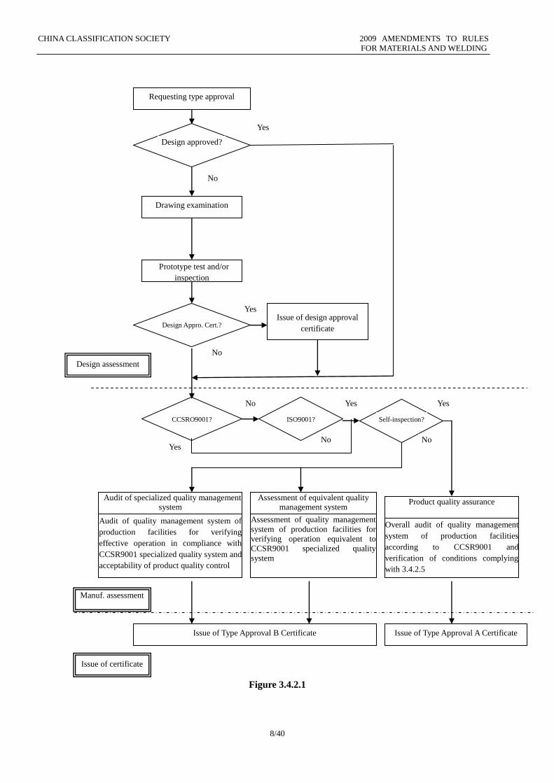
3.4.2 Process of type approval 3.4.2.1 The process of type approval is shown in Figure 3.4.2.1 below.
3.4.2.2 The applicant for type approval is to submit an application to CCS, stating the requested type
CHINA CLASSIFICATION SOCIETY 2009 AMENDMENTS TO RULES
FOR MATERIALS AND WELDING
7/40
approval and providing information on the manufacturer and his production location as well as all other
information necessary for the products to be approved.
3.4.2.3 While the process of type approval covers design approval (see Section 3 of this Chapter), a
separate application for design approval need not be made in respect to the products for which type
approval is sought, unless the manufacturer requests both type approval and issue of the Design Approval
Certificate.
3.4.2.4 The Type Approval B Certificate is issued to manufacturers meeting the following requirements:
(1) The product design complies with the applicable requirements of CCS rules and/or other applicable
standards.
(2) An effective specialized quality system for marine products is in place for ensuring the quality control
level required by the manufacturer.
3.4.2.5 The Type Approval A Certificate is issued only to those manufacturers who are allowed to carry
out the inspections and tests required by the rules without attendance by CCS Surveyor. A manufacturer
applying for type approval A is to meet the following requirements:
(1) The requirements for type approval B are met and 3.4.1.4(1)③ is complied with.
(2) Product quality is found upon CCS inspection experience and evaluation to be continually kept stable
during the period of holding the Type Approval B Certificate.
(3) The operation of the specialized quality system for marine product is capable of achieving at least the
results of the inspections and tests attended by CCS Surveyor.
CHINA CLASSIFICATION SOCIETY 2009 AMENDMENTS TO RULES
FOR MATERIALS AND WELDING
8/40
Figure 3.4.2.1
Drawing examination
Prototype test and/or
inspection
Audit of quality management system of
production facilities for verifying
effective operation in compliance with
CCSR9001 specialized quality system and
acceptability of product quality control
Assessment of quality management
system of production facilities for
verifying operation equivalent to
CCSR9001 specialized quality
system
Audit of specialized quality management system
Assessment of equivalent quality management system
Product quality assurance
Overall audit of quality management
system of production facilities
according to CCSR9001 and
verification of conditions complying
with 3.4.2.5
Issue of Type Approval B Certificate Issue of Type Approval A Certificate
Requesting type approval
Design assessment
Manuf. assessment
Issue of certificate
Design approved?
Yes
No
Design Appro. Cert.? Issue of design approval
certificate
Yes
No
CCSRO9001? ISO9001? Self-inspection?
No
No No
Yes Yes
Yes
CHINA CLASSIFICATION SOCIETY 2009 AMENDMENTS TO RULES
FOR MATERIALS AND WELDING
9/40
3.4.3 Design assessment 3.4.3.1 The drawing examination is to be in accordance with 3.3.2, Section 3 of this Chapter.
3.4.3.2 The type test is to be in accordance with 3.2.4, Section 2 of this Chapter.
3.4.3.3 Where the products, for which type approval is requested, have been design approved by CCS, the
confirmation of the Design Approval Certificate will suffice. Where the type test for design approval was
conducted without attendance by CCS Surveyor, a final test of product samples at workshop is to be
performed in lieu of the type test.
3.4.4 Assessment of manufacturing 3.4.4.1 Audit and/or assessment of the quality management system
(1) The specialized quality system for marine products established by the manufacturer is to be audited,
verifying that the system is appropriate for the products to be approved and complies with CCS
Requirements for the Quality Management System of Manufacturers of Marine Products (CCSR9001-2008)
and that the implemented system is capable of ensuring compliance of such products with CCS rules,
guidelines and/or other acceptable standards. If the manufacturer has a quality management system
certified by a State-approved certification body and at least complying with ISO9000 or equivalent quality
management standards, the system is to be assessed by CCS for verifying compliance with CCS
requirements for specialized quality management systems for marine products.
(2) The manufacturer is in particular to appropriately and sufficiently demonstrate the following aspects so
as to confirm the capability of the equipment used in production, inspection and test and the ability of the
personnel having influence on product quality to meet the specified level of product quality consistently:
① capability and test conditions of inspection, test and measurement equipment;
② inspection and test personnel;
③ technologies and operators of essential processes;
④ duties and qualifications of personnel performing quality inspection and control;
⑤ documented purchase control procedure (if applicable), preparation and maintenance of lists of
suppliers of raw materials, main components and parts, submission to CCS for information;
⑥ Quality control methods, including control of subcontractors (if applicable).
(3) The manufacturer is to maintain a quality manual in accordance with quality standards. If the quality
system certified by an appropriate certification body is found upon assessment to comply with CCS
requirements for specialized quality systems, the quality manual approved by such body is to be submitted
to CCS for information.
3.4.4.2 Audit of the manufacturing process
(1) A quality control plan for the products within the approval scope is to be established by the
manufacturer and submitted to CCS for approval. This quality control plan is to describe the quality
assurance and control methods used in the manufacturing process according to the technical requirements
or standards of the products, reflecting in particular the inspection and test requirements of CCS rules,
guidelines and/or conventions.
(2) Samples or representative pieces of the products within the approval scope are to be provided by the
manufacturer to the Surveyor for verifying that they are manufactured according to the design documents.
3.4.5 Issue and validity of Type Approval Certificate
3.4.5.1 The CCS branch performing type approval will issue one of the following Type Approval B
Certificates to a manufacturer for whom the design assessment and the assessment of manufacturing have
been completed according to 3.4.3 and 3.4.4 respectively and who is found to meet the conditions of
3.4.2.4:
(1) Short-term Type Approval B Certificate valid for not more than 6 months (only for manufacturers and
their products approved for the first time);
(2) Full-term Type Approval B Certificate valid for not more than 4 years.
3.4.5.2 Before the expiry date of a short-term Type Approval B Certificate, a follow-up audit is to be
carried out and upon satisfactory audit, a full-term Type Approval B Certificate will be issued for a period
not exceeding 4 years. The scope of the follow-up audit depends on the initial approval, including at least a
verification of remedial actions taken for any nonconformity found during the initial approval.
3.4.5.3 The related Management Department of CCS Headquarters will issue the Type Approval A
Certificate for a period not exceeding 4 years to a manufacturer at his request for whom the design
assessment and the assessment of manufacturing have been completed according to 3.4.3 and 3.4.4
respectively and who is found to comply with the requirements of 3.4.2.5.
CHINA CLASSIFICATION SOCIETY 2009 AMENDMENTS TO RULES
FOR MATERIALS AND WELDING
10/40
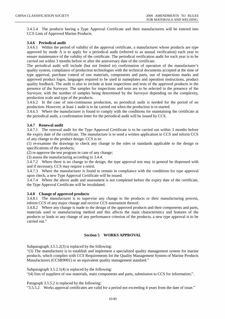
3.4.5.4 The products having a Type Approval Certificate and their manufacturers will be entered into
CCS Lists of Approved Marine Products.
3.4.6 Periodical audit 3.4.6.1 Within the period of validity of the approval certificate, a manufacturer whose products are type
approved by mode A is to apply for a periodical audit (referred to as annual verification) each year to
ensure maintenance of the validity of the certificate. The periodical verification audit for each year is to be
carried out within 3 months before or after the anniversary date of the certificate.
The periodical audit will include (but not limited to) confirmation of operation of the manufacturer’s
quality system, compliance of production technologies with the technical documents accepted at the time of
type approval, purchase control of raw materials, components and parts, use of inspections marks and
approved product logos, languages required to be used in nameplates and operation instructions, product
quality feedback. The audit is also to include at least inspections and tests of the approved products in the
presence of the Surveyor. The samples for inspections and tests are to be selected in the presence of the
Surveyor, with the number of samples being determined by the Surveyor depending on the complexity,
production scale and type of the products.
3.4.6.2 In the case of non-continuous production, no periodical audit is needed for the period of no
production. However, at least 1 audit is to be carried out when the production is re-started.
3.4.6.3 Where the manufacturer is found to comply with the conditions for maintaining the certificate at
the periodical audit, a confirmation letter for the periodical audit will be issued by CCS.
3.4.7 Renewal audit 3.4.7.1 The renewal audit for the Type Approval Certificate is to be carried out within 3 months before
the expiry date of the certificate. The manufacture is to send a written application to CCS and inform CCS
of any change to the product design. CCS is to:
(1) re-examine the drawings to check any change to the rules or standards applicable to the design or
specifications of the products;
(2) re-approve the test program in case of any change;
(3) assess the manufacturing according to 3.4.4.
3.4.7.2 Where there is no change to the design, the type approval test may in general be dispensed with
and if necessary, CCS may require a retest.
3.4.7.3 Where the manufacturer is found to remain in compliance with the conditions for type approval
upon check, a new Type Approval Certificate will be issued.
3.4.7.4 Where the above audit and assessment is not completed before the expiry date of the certificate,
the Type Approval Certificate will be invalidated.
3.4.8 Change of approved products 3.4.8.1 The manufacturer is to supervise any change to the products or their manufacturing process,
inform CCS of any major change and receive CCS assessment thereof.
3.4.8.2 Where any change is made to the design of the approved products and their components and parts,
materials used or manufacturing method and this affects the main characteristics and features of the
products or leads to any change of any performance criterion of the products, a new type approval is to be
carried out.”
Section 5 WORKS APPROVAL
Subparagraph 3.5.1.2(3) is replaced by the following:
“(3) The manufacturer is to establish and implement a specialized quality management system for marine
products, which complies with CCS Requirements for the Quality Management System of Marine Products
Manufacturers (CCSR9001) or an equivalent quality management standard.”
Subparagraph 3.5.2.1(4) is replaced by the following:
“(4) lists of suppliers of raw materials, main components and parts, submission to CCS for information;”.
Paragraph 3.5.5.2 is replaced by the following:
“3.5.5.2 Works approval certificates are valid for a period not exceeding 4 years from the date of issue.”
CHINA CLASSIFICATION SOCIETY 2009 AMENDMENTS TO RULES
FOR MATERIALS AND WELDING
11/40
The full text of paragraph 3.5.6 is replaced by the following:
“3.5.6 Periodical audit
3.5.6.1 The periodical audit will include (but not limited to) confirmation of operation of the
manufacturer’s quality system, compliance of production technologies with the technical documents
accepted at the time of type approval, purchase control of raw materials, components and parts, use of
inspections marks and approved product logos, languages required to be used in nameplates and operation
instructions, product quality feedback.
3.5.6.2 Where upon works approval, all inspections and tests required by rules, guidelines and applicable
standards are carried out in the presence of CCS Surveyor to the products installed and/or used on board
ships classed with CCS, all or a part of product tests may be dispensed with for the periodical verification.
3.5.6.3 Where the manufacturer is found to comply with the conditions for maintaining the Works
Approval Certificate at the annual verification, a confirmation letter for the annual verification will be
issued by CCS.”
CHINA CLASSIFICATION SOCIETY 2009 AMENDMENTS TO RULES
FOR MATERIALS AND WELDING
12/40
PART ONE METALLIC MATERIALS
CHAPTER 2 MATERIAL TESTS
Section 8 CRACK TIP OPENING DISPLACEMENT (CTOD) TEST FOR METALLIC
MATERIALS
In paragraph 2.8.2.3, the formula and the subsequent parts are replaced by the following:
“Fmax = kBW(Rp0.2 + Rm)
where: k – load coefficient, for steel, to be not more than 0.016, for weld, to be between 0.0117 and
0.0145;
B – specimen breadth, in mm;
W – specimen height, in mm;
Rp0.2 – proof strength of test material, in N/mm2;
Rm – tensile strength of test material, in N/mm2.
CHINA CLASSIFICATION SOCIETY 2009 AMENDMENTS TO RULES
FOR MATERIALS AND WELDING
13/40
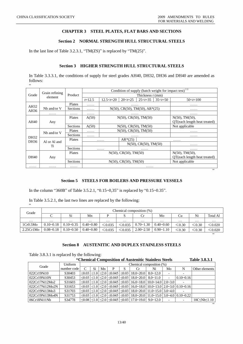
CHAPTER 3 STEEL PLATES, FLAT BARS AND SECTIONS
Section 2 NORMAL STRENGTH HULL STRUCTURAL STEELS
In the last line of Table 3.2.3.1, “TM(ZS)” is replaced by “TM(25)”.
Section 3 HIGHER STRENGTH HULL STRUCTURAL STEELS
In Table 3.3.3.1, the conditions of supply for steel grades AH40, DH32, DH36 and DH40 are amended as
follows:
“
Grade Grain refining
element Product
Condition of supply (batch weight for impact test)①②
Thickness t (mm)
t=12.5 12.5<t=20 20<t=25 25<t=35 35<t=50 50<t=100
AH32
AH36
Nb and/or V
Plates …… …… ……
Sections …… N(50), CR(50), TM(50), AR*(25) ……
…… …… …… …… ……
AH40 Any
Plates A(50) N(50), CR(50), TM(50) N(50), TM(50),
QT(each length heat treated)
Sections A(50) N(50), CR(50), TM(50) Not applicable
DH32
DH36
Nb and/or V Plates …… N(50), CR(50), TM(50) ……
Sections …… …… ……
Al or Al and
Ti
Plates …… AR*(25) ……
N(50), CR(50), TM(50) ……
Sections …… …… ……
DH40 Any
Plates N(50), CR(50), TM(50) N(50), TM(50),
QT(each length heat treated)
Sections N(50), CR(50), TM(50) Not applicable
…… …… …… ……
”
Section 5 STEELS FOR BOILERS AND PRESSURE VESSELS
In the column “360B” of Table 3.5.2.1, “0.15~0,35” is replaced by “0.15~0.35”.
In Table 3.5.2.1, the last two lines are replaced by the following:
“
Grade Chemical composition (%)
C Si Mn P S Cr Mo Cu Ni Total Al
… … … … … … … … … … …
1Cr0.5Mo 0.10~0.18 0.10~0.35 0.40~0.80 ≤0.035 ≤0.035 0.70~1.30 0.40~0.60 ≤0.30 ≤0.30 ≤0.020
2.25Cr1Mo 0.08~0.18 0.10~0.50 0.40~0.80 ≤0.035 ≤0.035 2.00~2.50 0.90~1.10 ≤0.30 ≤0.30 ≤0.020
”
Section 8 AUSTENITIC AND DUPLEX STAINLESS STEELS
Table 3.8.3.1 is replaced by the following:
“Chemical Composition of Austenitic Stainless Steels Table 3.8.3.1
Grade Uniform
number code
Chemical composition (%)
C Si Mn P S Cr Ni Mo N Other elements
022Cr19Ni10 S30403 ≤0.03 ≤1.0 ≤2.0 ≤0.045 ≤0.03 18.0~20.0 8.0~12.0 - -
022Cr19Ni10N S30453 ≤0.03 ≤1.0 ≤2.0 ≤0.045 ≤0.03 18.0~20.0 8.0~11.0 - 0.10~0.16
022Cr17Ni12Mo2 S31603 ≤0.03 ≤1.0 ≤2.0 ≤0.045 ≤0.03 16.0~18.0 10.0~14.0 2.0~3.0 -
022Cr17Ni12Mo2N S31653 ≤0.03 ≤1.0 ≤2.0 ≤0.045 ≤0.03 16.0~18.0 10.0~13.0 2.0~3.0 0.10~0.16
022Cr19Ni13Mo3 S31703 ≤0.03 ≤1.0 ≤2.0 ≤0.045 ≤0.03 18.0~20.0 11.0~15.0 3.0~4.0 -
022Cr19Ni13Mo4N S31753 ≤0.03 ≤1.0 ≤2.0 ≤0.045 ≤0.03 18.0~20.0 11.0~15.0 3.0~4.0 0.10~0.22
06Cr18Ni11Nb S34778 ≤0.08 ≤1.0 ≤2.0 ≤0.045 ≤0.03 17.0~19.0 9.0~12.0 - - 10C≤Nb≤1.10
”
CHINA CLASSIFICATION SOCIETY 2009 AMENDMENTS TO RULES
FOR MATERIALS AND WELDING
14/40
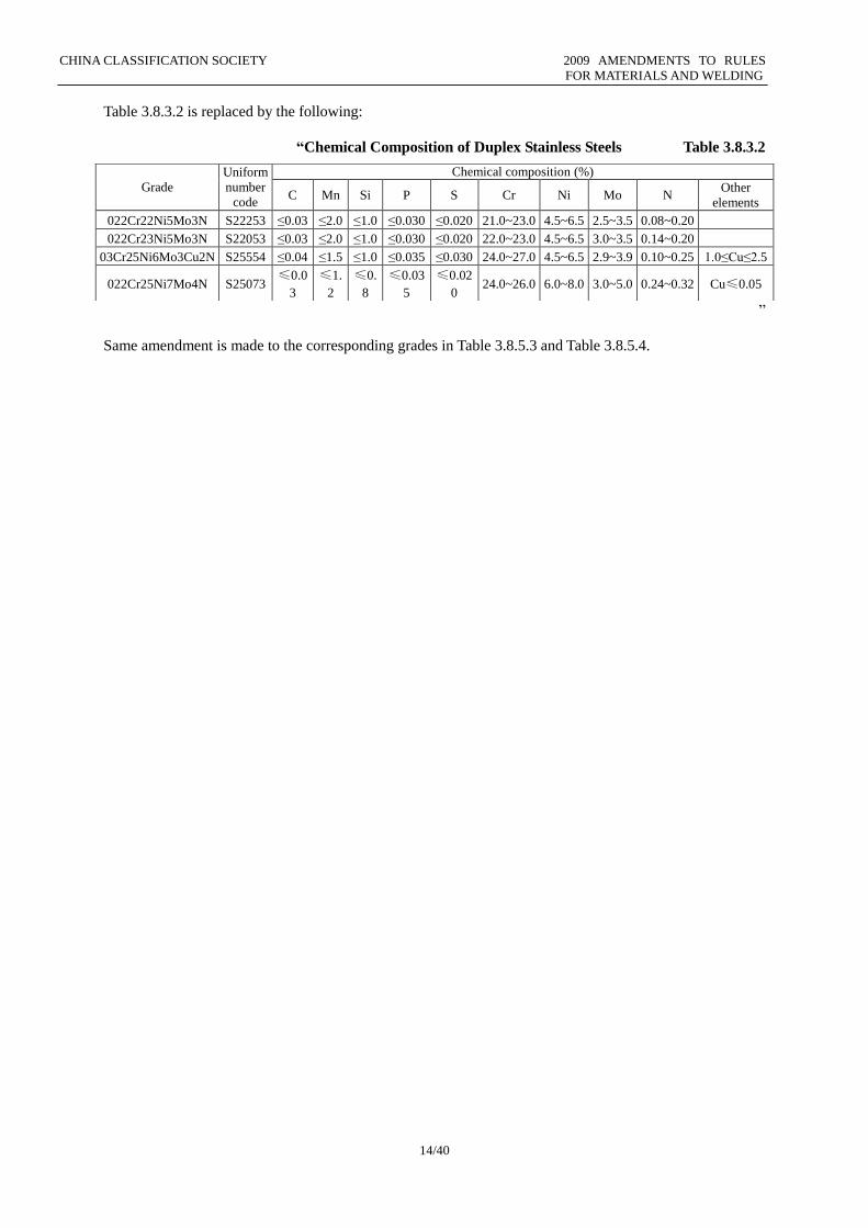
Table 3.8.3.2 is replaced by the following:
“Chemical Composition of Duplex Stainless Steels Table 3.8.3.2
”
Same amendment is made to the corresponding grades in Table 3.8.5.3 and Table 3.8.5.4.
Grade
Uniform
number
code
Chemical composition (%)
C Mn Si P S Cr Ni Mo N Other
elements
022Cr22Ni5Mo3N S22253 ≤0.03 ≤2.0 ≤1.0 ≤0.030 ≤0.020 21.0~23.0 4.5~6.5 2.5~3.5 0.08~0.20
022Cr23Ni5Mo3N S22053 ≤0.03 ≤2.0 ≤1.0 ≤0.030 ≤0.020 22.0~23.0 4.5~6.5 3.0~3.5 0.14~0.20
03Cr25Ni6Mo3Cu2N S25554 ≤0.04 ≤1.5 ≤1.0 ≤0.035 ≤0.030 24.0~27.0 4.5~6.5 2.9~3.9 0.10~0.25 1.0≤Cu≤2.5
022Cr25Ni7Mo4N S25073 ≤0.0
3
≤1.
2
≤0.
8
≤0.03
5
≤0.02
0 24.0~26.0 6.0~8.0 3.0~5.0 0.24~0.32 Cu≤0.05
CHINA CLASSIFICATION SOCIETY 2009 AMENDMENTS TO RULES
FOR MATERIALS AND WELDING
15/40
CHAPTER 4 STEEL PIPES AND TUBES
Section 2 SEAMLESS PRESSURE PIPES
In Table 4.2.2.2, “Total G0.70” is replaced by “Total ≤0.70”.
Section 4 BOILER AND SUPERHEATER TUBES
In Table 4.4.4.1, “1Cl0.5Mo” is replaced by “1Cr0.5Mo”.
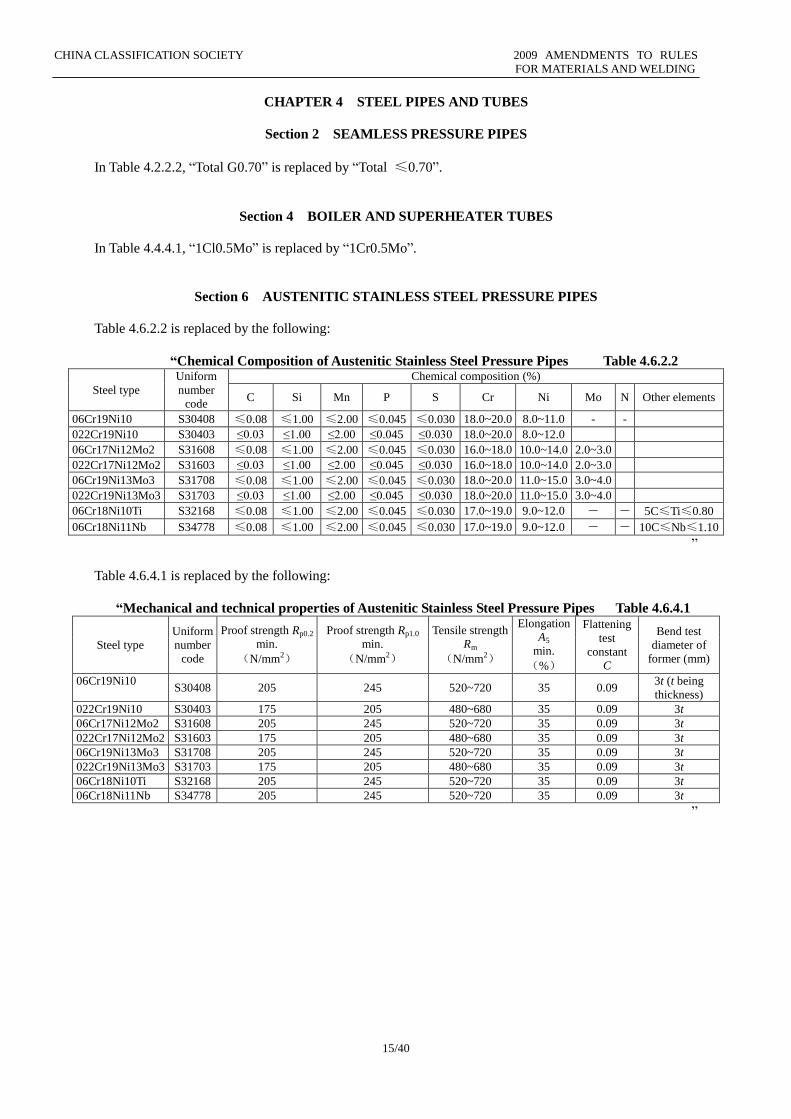
Section 6 AUSTENITIC STAINLESS STEEL PRESSURE PIPES
Table 4.6.2.2 is replaced by the following:
“Chemical Composition of Austenitic Stainless Steel Pressure Pipes Table 4.6.2.2
Steel type
Uniform
number
code
Chemical composition (%)
C Si Mn P S Cr Ni Mo N Other elements
06Cr19Ni10 S30408 ≤0.08 ≤1.00 ≤2.00 ≤0.045 ≤0.030 18.0~20.0 8.0~11.0 - -
022Cr19Ni10 S30403 ≤0.03 ≤1.00 ≤2.00 ≤0.045 ≤0.030 18.0~20.0 8.0~12.0
06Cr17Ni12Mo2 S31608 ≤0.08 ≤1.00 ≤2.00 ≤0.045 ≤0.030 16.0~18.0 10.0~14.0 2.0~3.0
022Cr17Ni12Mo2 S31603 ≤0.03 ≤1.00 ≤2.00 ≤0.045 ≤0.030 16.0~18.0 10.0~14.0 2.0~3.0
06Cr19Ni13Mo3 S31708 ≤0.08 ≤1.00 ≤2.00 ≤0.045 ≤0.030 18.0~20.0 11.0~15.0 3.0~4.0
022Cr19Ni13Mo3 S31703 ≤0.03 ≤1.00 ≤2.00 ≤0.045 ≤0.030 18.0~20.0 11.0~15.0 3.0~4.0
06Cr18Ni10Ti S32168 ≤0.08 ≤1.00 ≤2.00 ≤0.045 ≤0.030 17.0~19.0 9.0~12.0 - - 5C≤Ti≤0.80
06Cr18Ni11Nb S34778 ≤0.08 ≤1.00 ≤2.00 ≤0.045 ≤0.030 17.0~19.0 9.0~12.0 - - 10C≤Nb≤1.10
”
Table 4.6.4.1 is replaced by the following:
“Mechanical and technical properties of Austenitic Stainless Steel Pressure Pipes Table 4.6.4.1
Steel type
Uniform
number
code
Proof strength Rp0.2
min.
(N/mm2)
Proof strength Rp1.0
min.
(N/mm2)
Tensile strength
Rm
(N/mm2)
Elongation
A5
min.
(%)
Flattening
test
constant
C
Bend test
diameter of
former (mm)
06Cr19Ni10 S30408 205 245 520~720 35 0.09
3t (t being
thickness)
022Cr19Ni10 S30403 175 205 480~680 35 0.09 3t
06Cr17Ni12Mo2 S31608 205 245 520~720 35 0.09 3t
022Cr17Ni12Mo2 S31603 175 205 480~680 35 0.09 3t
06Cr19Ni13Mo3 S31708 205 245 520~720 35 0.09 3t
022Cr19Ni13Mo3 S31703 175 205 480~680 35 0.09 3t
06Cr18Ni10Ti S32168 205 245 520~720 35 0.09 3t
06Cr18Ni11Nb S34778 205 245 520~720 35 0.09 3t
”
CHINA CLASSIFICATION SOCIETY 2009 AMENDMENTS TO RULES
FOR MATERIALS AND WELDING
16/40
CHAPTER 7 IRON CASTINGS
Section 2 GREY IRON CASTINGS
New note ③ is added at the end of Table 7.2.4.1 as follows:
“③ Where attached test samples are employed, the mechanical properties of grey iron castings may be
accepted according to recognized national/international standards.”
CHAPTER 10 EQUIPMENT
Section 2 ANCHOR CHAIN CABLES AND ACCESSORIES
The following words are added at the end of paragraph 10.2.10.1:
“The certificate number may be abbreviation or other equivalent marking, and is to be indicated in the
corresponding certificate.”
CHINA CLASSIFICATION SOCIETY 2009 AMENDMENTS TO RULES
FOR MATERIALS AND WELDING
17/40
PART TWO NON-METALLIC MATERIALS
CHAPTER 2 PLASTIC MATERIALS
Section 2 RAW MATERIALS
In subparagraph 2.2.6.5(2), “Water absorption” is replaced by “Water absorption rate”.
In subparagraph 2.2.7.5(6), “Water absorption” is replaced by “Water absorption rate”.
In subparagraph 2.2.7.5(7), “Oil absorption” is replaced by “Oil absorption rate”.
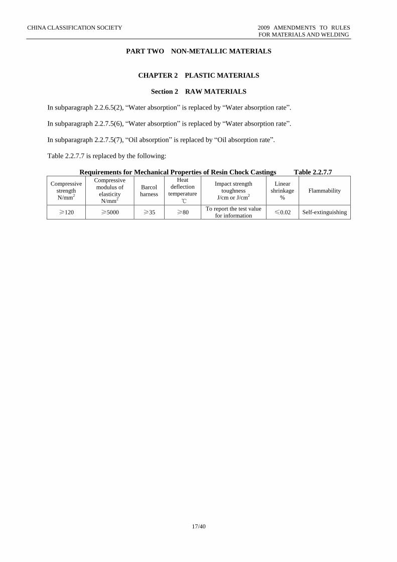
Table 2.2.7.7 is replaced by the following:
Requirements for Mechanical Properties of Resin Chock Castings Table 2.2.7.7
Compressive
strength
N/mm2
Compressive
modulus of
elasticity
N/mm2
Barcol
harness
Heat
deflection
temperature
℃
Impact strength
toughness
J/cm or J/cm2
Linear
shrinkage
%
Flammability
≥120 ≥5000 ≥35 ≥80 To report the test value
for information ≤0.02 Self-extinguishing
CHINA CLASSIFICATION SOCIETY 2009 AMENDMENTS TO RULES
FOR MATERIALS AND WELDING
18/40
CHAPTER 4 PLASTIC PIPES AND FITTINGS
Section 2 MATERIAL, DESIGN, MANUFACTURE AND STRENGTH TEST
In subparagraph 4.2.1.3(5), “Content of filler or reinforcing material” is replaced by “Content of filler or
pigment”.
CHINA CLASSIFICATION SOCIETY 2009 AMENDMENTS TO RULES
FOR MATERIALS AND WELDING
19/40
CHAPTER 7 FIBER ROPES
A new Section 2 is added as follows:
“Section 2 FIBER ROPES FOR OFFSHORE MOORING
7.2.1 Application
7.2.1.1 The requirements of this Section apply to synthetic fiber ropes used in the mooring of offshore
installations.
7.2.2 Raw materials
7.2.2.1 Fiber ropes used in the mooring of offshore installations may be made of polyester (polyethylene
terephthalate), Aramid (aromatic polyamide), HMPE (high modulus polyethylene) and nylon (polyamide).
If it is intended to use other materials, sufficient data are to be available to show compliance of their
properties with service requirements.
7.2.2.2 The material for the manufacture of fiber ropes used in the mooring of offshore installations is to
be of good and consistent quality and resistant to corrosion and aging.
7.2.2.3 The maker is to provide fiber material of each batch rope with quality guarantee attached with
following property parameters:
(1) fiber type and grade;
(2) linear density;
(3) dry breaking strength and elongation;
(4) wet breaking strength and elongation (only to nylon);
(5) wet yarn-on-yarn abrasion property;
(6) dry creep property;
(7) type of marine finish added and relevant specifications (Technical Data Sheet) (if any);
(8) content of marine finish and description of water-solubility.
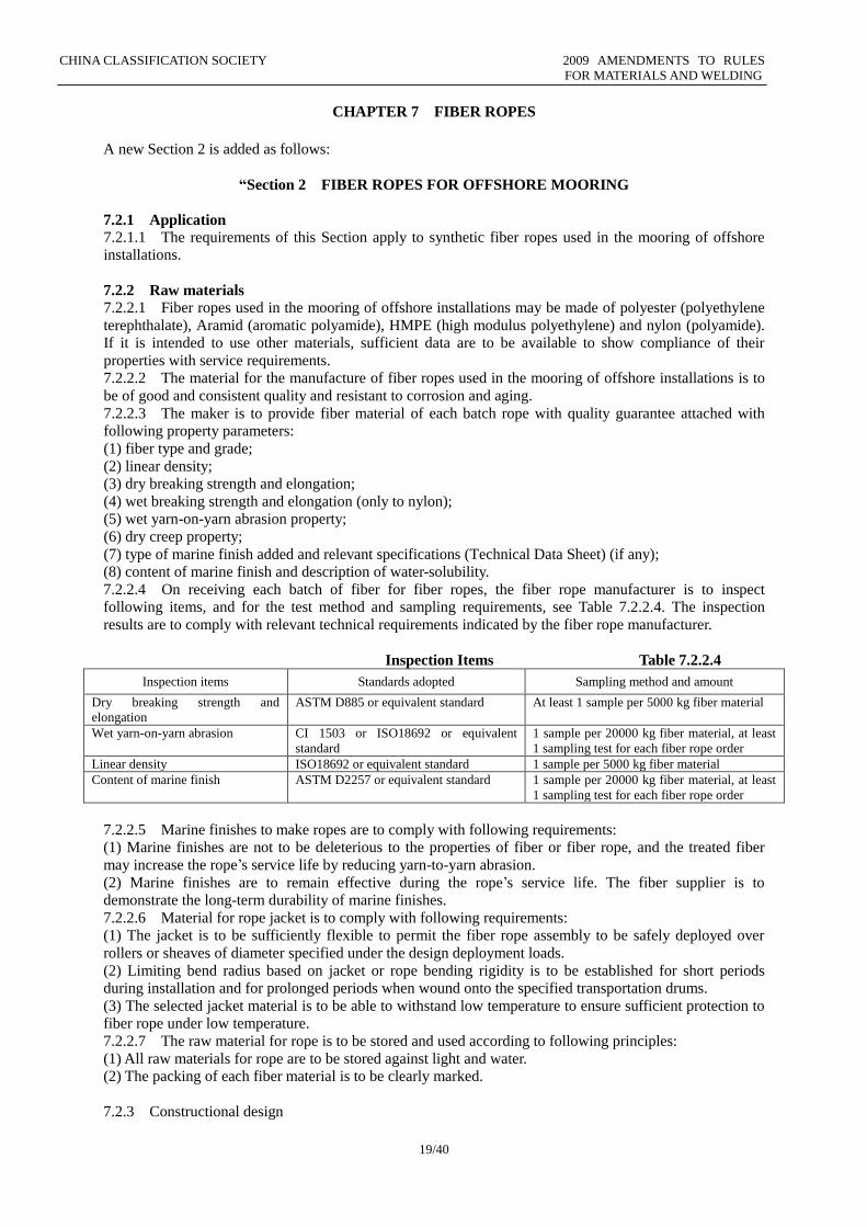
7.2.2.4 On receiving each batch of fiber for fiber ropes, the fiber rope manufacturer is to inspect
following items, and for the test method and sampling requirements, see Table 7.2.2.4. The inspection
results are to comply with relevant technical requirements indicated by the fiber rope manufacturer.
Inspection Items Table 7.2.2.4
Inspection items Standards adopted Sampling method and amount
Dry breaking strength and
elongation
ASTM D885 or equivalent standard At least 1 sample per 5000 kg fiber material
Wet yarn-on-yarn abrasion CI 1503 or ISO18692 or equivalent
standard
1 sample per 20000 kg fiber material, at least
1 sampling test for each fiber rope order
Linear density ISO18692 or equivalent standard 1 sample per 5000 kg fiber material
Content of marine finish ASTM D2257 or equivalent standard 1 sample per 20000 kg fiber material, at least
1 sampling test for each fiber rope order
7.2.2.5 Marine finishes to make ropes are to comply with following requirements:
(1) Marine finishes are not to be deleterious to the properties of fiber or fiber rope, and the treated fiber
may increase the rope’s service life by reducing yarn-to-yarn abrasion.
(2) Marine finishes are to remain effective during the rope’s service life. The fiber supplier is to
demonstrate the long-term durability of marine finishes.
7.2.2.6 Material for rope jacket is to comply with following requirements:
(1) The jacket is to be sufficiently flexible to permit the fiber rope assembly to be safely deployed over
rollers or sheaves of diameter specified under the design deployment loads.
(2) Limiting bend radius based on jacket or rope bending rigidity is to be established for short periods
during installation and for prolonged periods when wound onto the specified transportation drums.
(3) The selected jacket material is to be able to withstand low temperature to ensure sufficient protection to
fiber rope under low temperature.
7.2.2.7 The raw material for rope is to be stored and used according to following principles:
(1) All raw materials for rope are to be stored against light and water.
(2) The packing of each fiber material is to be clearly marked.
7.2.3 Constructional design
CHINA CLASSIFICATION SOCIETY 2009 AMENDMENTS TO RULES
FOR MATERIALS AND WELDING
20/40
7.2.3.1 The typical construction of fiber ropes for offshore mooring are parallel fiber (parallel yarn),
parallel twisted-strand (multi-rope), parallel braided-strand (multi-rope), six-strand (with non-load-bearing
core), seven-strand (six strand with load-bearing core), eighteen-strand (6+12), thirty-six-strand (6+12+18),
plaited (eight-strand rope), single-braid (twelve-strand rope) and double-braid.
7.2.3.2 The design of protective jacket is to comply with following requirements:
(1) The jacket is to be able to protect the rope from external abrasion which may occur during
transportation, handling at installation or other causes.
(2) The fiber rope assembly is not to be used in areas of high turbidity unless protected by suitable jackets
which exclude particle penetration while allowing water ingress.
(3) If fiber ropes are used where serious fishbite may occur, the rope is to be adequately protected by
appropriate jacket design.
(4) Typical jackets may be braided, extruded, tape-wound or otherwise applied.
(5) Rope jackets are to be tightly fixed to the termination area to prevent slippage of the jacket away from
the termination.
7.2.3.3 The design of end termination is to comply with following requirements:
(1) For synthetic fiber rope assemblies for deepwater mooring, the typical type of end termination is spliced
eye.
(2) Rope Minimum Breaking Strength (MBS) is representative of the rope assembly break strength, which
includes termination and/or rope core failures. MBS of the fiber rope as quoted by the rope supplier is to
take into account the strength efficiencies of all terminations within the rope assembly. Break strength of
the rope is to be determined through testing on prototype or production ropes of the same rope construction,
material and termination design as those which will be used in the actual mooring installation.
7.2.4 Manufacture
7.2.4.1 Fiber ropes for offshore mooring are to be manufactured by the factories approved by CCS.
7.2.4.2 The rope manufacturer is to have production, testing equipment and manufacturing capability
necessary for making fiber ropes as well as perfect quality assurance system to ensure consistent physical
and mechanical properties of the fiber ropes.
7.2.4.3 Prior to production, the manufacture is to submit relevant Manufacturing Specifications to the
classification society for approval, which includes at least:
(1) fiber assembly process;
(2) yarn assembly process;
(3) strand assembly process;
(4) rope jacketing process (if applicable);
(5) termination handling process.
7.2.4.4 The production process is to be strictly according to the approved Manufacturing Specifications.
Where there is any change to the process, the Manufacturing Specification is to be submitted to the
classification society for reapproval.
7.2.5 Inspection of fiber rope 7.2.5.1 For fiber rope product for offshore mooring, external visual inspection is to be carried out to
verify compliance of rope structure with design and to check the evenness of lay-up.
7.2.5.2 One sample is to be selected from each coil of fiber rope product to inspect linear density, wet
breaking load and nominal diameter.
7.2.5.3 Five specimens are to be taken for wet breaking test and nominal diameter inspection:
(1) The specimens are to be terminated in the same manner as that which will be used on the rope assembly.
The specimen length is to be at least 40 times nominal rope diameter between rope ends of terminations.
(2) The specimen is not to have been previously tensioned to more than 5% of its estimated breaking
strength.
(3) The entire specimen including terminations is to be soaked in fresh water between 22 and 26 hours
before testing. The specimen is to be tested as soon as practical after being removed from the water. If there
is a delay of more than 12 hours after soaking, the specimen is to be soaked again for an additional 2 hours
for each 24-hour period of delay up to a maximum of an additional 24 hours of soaking before the rope is
tested. The temperature of the water is to be maintained between 15℃ and 25℃.
(4) Preload of 1% estimated MBS is applied to the fiber rope to measure its nominal diameter.
(5) Cycle the rope ten times from 1% of estimated MBS (initial tension) to 50% of estimated MBS. On the
eleventh cycle, apply force to the rope until it breaks.
CHINA CLASSIFICATION SOCIETY 2009 AMENDMENTS TO RULES
FOR MATERIALS AND WELDING
21/40
(6) The rate of travel of the pulling head during the break test is to be such that the rope is loaded to 20% of
its estimated MBS in not less than 2 sec. nor more than 30 sec.
(7) The breaking tension and the location and nature of break are to be recorded for each specimen.
(8) The average wet break strength and the standard deviation of wet break strength are to be calculated.
7.2.5.4 Linear density test for fiber rope is to be carried out according to paragraph 7.1.4.4, Section 1 of
this Chapter.
7.2.6 Storage and transportation of fiber rope
7.2.6.1 During storage and transportation, necessary measures are to be taken to protect synthetic fiber
ropes for offshore mooring from the effects of ultra-violet radiation and moisture, and the ambient
temperature is not to exceed the manufacturer’s recommended limit.
7.2.6.2 In general, synthetic fiber ropes for offshore mooring are stored/wrapped onto a reel. Adequate
protection is to be provided to prevent chafing of the ropes in the storage reel.
7.2.6.3 It is to be noted that the bending radius at termination is not to be less than the manufacturer’s
recommended allowable minimum bending radius.
7.2.6.4 Metallic end fittings are to be twisted or kept separately.
7.2.7 Marking and certificate
7.2.7.1 Each coil of completed rope is to be identified at a clearly visible position (such as protective
jacket) with the rope name, diameter and length and the maker’s name (or brand name).
7.2.7.2 The fiber rope which has been accepted is to be attached with a label detailing the rope No.,
material, construction and CCS stamp in a secure manner (lead sealing is recommended) at the end of each
rope.
7.2.7.3 The manufacturer is to provide qualified fiber ropes with a qualification certificate including at
least:
(1) product name, type and No.;
(2) material of fiber ropes;
(3) linear density of fiber ropes;
(4) length and diameter of a whole fiber rope coil;
(5) construction of fiber ropes;
(6) normal breaking load of fiber ropes and actual wet breaking load;
(7) date of manufacture and inspection;
(8) highest service temperature;
(9) shelf-life of product.”
CHINA CLASSIFICATION SOCIETY 2009 AMENDMENTS TO RULES
FOR MATERIALS AND WELDING
22/40
PART THREE WELDING
CHAPTER 1 GENERAL
Section 2 TESTING
In line 1 column 2 of Table 1.2.4.2, “Yield strength of test material (N/mm2)” is replaced by “Specified
yield strength of test material (N/mm2)”.
A new sentence is added at the end of paragraph 1.2.4.4 as follows:
“If it is impossible, notching the surface of weld is allowed. The depth of the notches is not to be greater
than 20% of the throat thickness. ”
CHINA CLASSIFICATION SOCIETY 2009 AMENDMENTS TO RULES
FOR MATERIALS AND WELDING
23/40
CHAPTER 2 WELDING CONSUMABLES
Section 4 WIRE-FLUX COMBINATIONS FOR SUBMERGED ARC AUTOMATIC WELDING
In paragraph 2.4.3.2, the first sentence “The test plates are to be assembled as shown in Figure 2.4.3.2 and
are to be welded in the down hand welding position.” is replaced by “The test plates are to be assembled as
shown in Figure 2.4.3.2 and are to be welded in the down hand welding position with wire of maximum
diameter applied for approval.”
Paragraph 2.4.5.1 is replaced by the following:
“2.4.5.1 Two butt weld test assemblies for two-run technique with different thicknesses are to be prepared
with test plates of the corresponding strength in accordance with the toughness grades of the wire-flux
combinations. The thickness of test plate is shown in Table 2.4.5.1. The width of each test plate is not to be
less than 150mm, and the length is to be appropriate to the size and number of specimens.
Requirements of Different Grade of Welding Consumables to the Plate Thickness of Butt Specimen
for Two-run Technique Table 2.4.5.1
Grade of welding consumables Thickness of thinner test plate (mm) Thickness of thicker test plate (mm)
1, 1Y 12~15 20~25
2, 2Y, 3, 3Y, 4Y, 2Y40, 3Y40, 4Y40 20~25① 30~35
①
Note: ① A limitation of the approval to the medium range (up to the maximum welded plate thickness) may be agreed to
by CCS. Test assemblies are then to be welded using plates of 12 to 15 mm and 20 to 25 mm irrespective of the
grade for which the approval is requested. This is applicable to thicknesses up to 25 mm only.”
In paragraph 2.4.5.2, “The plate thickness matching the maximum diameter of wires and the edge
preparation” is replaced by “The maximum diameter of wire and the edge preparation that may be used to
prepare test assemblies of different thicknesses”.
Section 5 WIRES AND WIRE-GAS COMBINATIONS FOR SEMI-AUTOMATIC AND
AUTOMATIC WELDING
In paragraph 2.5.1.1, “Wires and wire-gas combinations” is replaced by “Wires (including gas-protected
wire and self-protected wire) and wire-gas combinations”.
In paragraph 2.5.1.2, the existing words “Solid or” are deleted.
Paragraph 2.5.5.1 is replaced by the following:
“2.5.5.1 Fillet weld tests for the semi-automatic multi-run technique are to be carried out in the downhand
position. The tests are to be carried out in accordance with the requirements of 2.3.5 of this Chapter, except
that the sides of the assemblies are to be welded using respectively wires of the smallest and the largest
diameters for which approval is requested.”
Section 8 WELDING CONSUMABLES FOR STAINLESS STEEL
Table 2.8.2.1 is replaced by the following:
“Grade of Welding Consumables for Stainless Steel and Material Used for Approval Test
Table 2.8.2.1 Grade of welding
consumables
Parent material used for
approval
Grade of welding
consumables
Parent material used for
approval
304L 022Cr19Ni10 (S30403) 347 06Cr18Ni11Nb (S34778)
304LN 022Cr19Ni10N (S30453) 309L 06Cr23Ni13 (S30908)
316L 022Cr17Ni12Mo2 (S31603) 2205 022Cr23Ni5Mo3N (S22053)
316LN 022Cr17Ni12Mo2N (S31653) 2550 03Cr25Ni6Mo3Cu2N (S25554)
317L 022Cr19Ni13Mo3 (S31703) 2750 022Cr25Ni7Mo4N (S25073)
317LN 022Cr19Ni13Mo4N (S31753)
”
CHINA CLASSIFICATION SOCIETY 2009 AMENDMENTS TO RULES
FOR MATERIALS AND WELDING
24/40
CHAPTER 3 APPROVAL OF WELDING PROCEDURES
Section l GENERAL PROVISIONS
In subparagraph 3.1.4.5(2), the last sentence “Where a fillet weld is qualified by means of a butt weld test,
the throat thickness range qualified is to be based on the thickness of the butt weld test assembly.” is
deleted.
Paragraph 3.1.4.6 is replaced by the following:
“3.1.4.6 The application of external diameter of pipes is to comply with the requirements of Table 3.1.4.6.
Application of External Diameter of Pipes Table 3.1.4.6
External diameter of pipes
D (mm)
Application
D (mm)
D <168 0.5D ≤ d ≤ 2D
D≥168 d ≥ 0.5D (including plate)
”
A new sentence “Butt weld joints of pipes with external diameter not less than 168 mm apply to butt weld
joints of plates at corresponding position” is added at the end of paragraph 3.1.4.8.
Section 2 WELDING PROCEDURE TESTS FOR BUTT WELD JOINTS
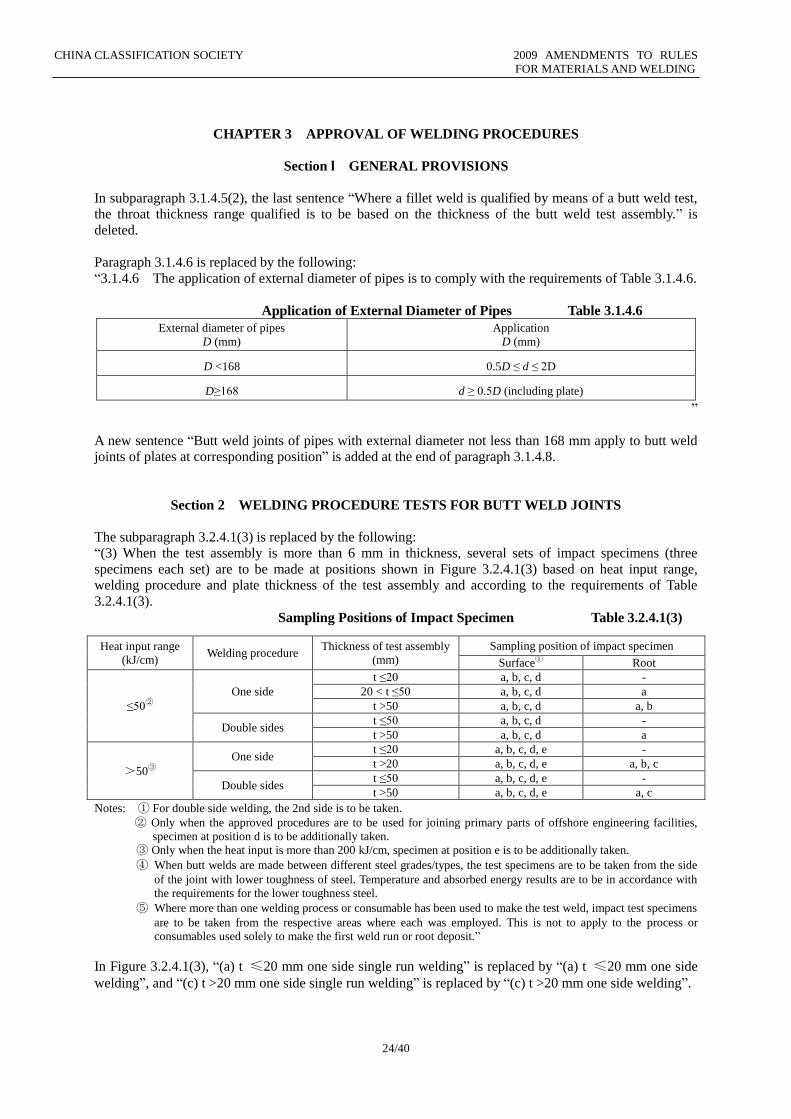
The subparagraph 3.2.4.1(3) is replaced by the following:
“(3) When the test assembly is more than 6 mm in thickness, several sets of impact specimens (three
specimens each set) are to be made at positions shown in Figure 3.2.4.1(3) based on heat input range,
welding procedure and plate thickness of the test assembly and according to the requirements of Table
3.2.4.1(3).
Sampling Positions of Impact Specimen Table 3.2.4.1(3)
Notes: ① For double side welding, the 2nd side is to be taken.
② Only when the approved procedures are to be used for joining primary parts of offshore engineering facilities,
specimen at position d is to be additionally taken.
③ Only when the heat input is more than 200 kJ/cm, specimen at position e is to be additionally taken.
④ When butt welds are made between different steel grades/types, the test specimens are to be taken from the side
of the joint with lower toughness of steel. Temperature and absorbed energy results are to be in accordance with
the requirements for the lower toughness steel.
⑤ Where more than one welding process or consumable has been used to make the test weld, impact test specimens
are to be taken from the respective areas where each was employed. This is not to apply to the process or
consumables used solely to make the first weld run or root deposit.”
In Figure 3.2.4.1(3), “(a) t ≤20 mm one side single run welding” is replaced by “(a) t ≤20 mm one side
welding”, and “(c) t >20 mm one side single run welding” is replaced by “(c) t >20 mm one side welding”.
Heat input range
(kJ/cm) Welding procedure
Thickness of test assembly
(mm)
Sampling position of impact specimen
Surface① Root
≤50②
One side
t ≤20 a, b, c, d -
20 < t ≤50 a, b, c, d a
t >50 a, b, c, d a, b
Double sides t ≤50 a, b, c, d -
t >50 a, b, c, d a
>50③
One side t ≤20 a, b, c, d, e -
t >20 a, b, c, d, e a, b, c
Double sides t ≤50 a, b, c, d, e -
t >50 a, b, c, d, e a, c
CHINA CLASSIFICATION SOCIETY 2009 AMENDMENTS TO RULES
FOR MATERIALS AND WELDING
25/40
CHAPTER 4 QUALIFICATION TESTS OF WELDERS
Section 1 GENERAL PROVISIONS
A new paragraph 4.1.1.3 is added as follows:
“4.1.1.3 The method of qualification tests of welders engaged in special product welding is to be
specially considered by CCS.”
The existing subparagraph 4.1.3.1(5) is deleted.
A new paragraph 4.1.3.2 is added as follows:
“4.1.3.2 The requirements for welders applying for upgrading are as follows:
(1) In general, the applicants are to take part in the tests grade by grade. In special cases, if agreed by the
Qualification Test Committee and approved by the responsible surveyor, the applicants may apply for the
tests of an appropriate grade according to his/her actual work range and operation skill.
(2) In general, only those who have more than 6 months’ actual working experience of one grade can apply
for upgrading test of next grade. Personnel applying for Grade III need to hold Grade II certificate and have
continuous working experience of more than 1 year.”
The existing paragraph 4.1.3.2 is renumbered accordingly.
Paragraph 4.1.4 is replaced by the following:
“4.1.4 Grades and classes of qualification tests of welders
4.1.4.1 According to type of products, qualification of welders is categorized as welders engaged in
welding of ships and offshore structures and welders engaged in welding of marine boilers and pressure
vessels. Grades of qualification tests of welders are categorized as Grades I, II and III for plates and Grades
IP, IIP, IIIP and IIIPR for pipes according to the welding positions. Grade T means underwater wet tack
welding.
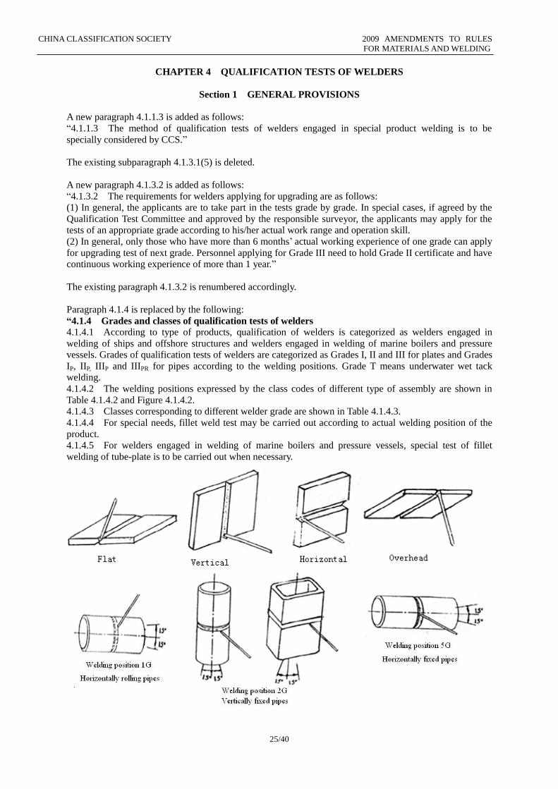
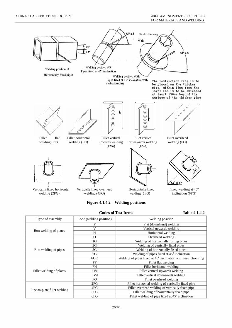
4.1.4.2 The welding positions expressed by the class codes of different type of assembly are shown in
Table 4.1.4.2 and Figure 4.1.4.2.
4.1.4.3 Classes corresponding to different welder grade are shown in Table 4.1.4.3.
4.1.4.4 For special needs, fillet weld test may be carried out according to actual welding position of the
product.
4.1.4.5 For welders engaged in welding of marine boilers and pressure vessels, special test of fillet
welding of tube-plate is to be carried out when necessary.
CHINA CLASSIFICATION SOCIETY 2009 AMENDMENTS TO RULES
FOR MATERIALS AND WELDING
26/40
Fillet flat
welding (FF) Fillet horizontal
welding (FH) Fillet vertical
upwards welding
(FVu)
Fillet vertical
downwards welding
(FVd)
Fillet overhead
welding (FO)
Vertically fixed horizontal
welding (2FG)
Vertically fixed overhead
welding (4FG)
Horizontally fixed
welding (5FG)
Fixed welding at 45o
inclination (6FG)
Figure 4.1.4.2 Welding positions
Codes of Test Items Table 4.1.4.2
Type of assembly Code (welding position) Welding position
Butt welding of plates
F Flat (downhand) welding
V Vertical upwards welding
H Horizontal welding
O Overhead welding
Butt welding of pipes
1G Welding of horizontally rolling pipes
2G Welding of vertically fixed pipes
5G Welding of horizontally fixed pipes
6G Welding of pipes fixed at 45o inclination
6GR Welding of pipes fixed at 45o inclination with restriction ring
Fillet welding of plates
FF Fillet flat welding
FH Fillet horizontal welding
FVu Fillet vertical upwards welding
FVd Fillet vertical downwards welding
FO Fillet overhead welding
Pipe-to-plate fillet welding
2FG Fillet horizontal welding of vertically fixed pipe
4FG Fillet overhead welding of vertically fixed pipe
5FG Fillet welding of horizontally fixed pipe
6FG Fillet welding of pipe fixed at 45o inclination
CHINA CLASSIFICATION SOCIETY 2009 AMENDMENTS TO RULES
FOR MATERIALS AND WELDING
27/40
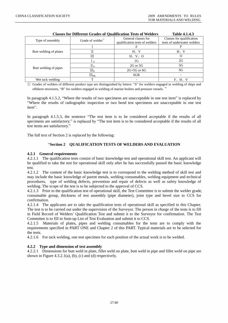
Classes for Different Grades of Qualification Tests of Welders Table 4.1.4.3
Type of assembly Grade of welder①
General classes for
qualification tests of welders
Classes for qualification
tests of underwater welders
Butt welding of plates
Ⅰ F F
Ⅱ H、V H、V
Ⅲ H、V、O O
Butt welding of pipes
ⅠP 1G 2G
ⅡP 2G or 5G 5G
ⅢP 2G+5G or 6G 6G
ⅢPR 6GR -
Wet tack welding T - F、H、V
① Grades of welders of different product type are distinguished by letters: “S” for welders engaged in welding of ships and
offshore structures, “B” for welders engaged in welding of marine boilers and pressure vessels. ”
In paragraph 4.1.5.2, “Where the results of two specimens are unacceptable in one test item” is replaced by
“Where the results of radiographic inspection or two bend test specimens are unacceptable in one test
item”.
In paragraph 4.1.5.3, the sentence “The test item is to be considered acceptable if the results of all
specimens are satisfactory.” is replaced by “The test item is to be considered acceptable if the results of all
test items are satisfactory.”
The full text of Section 2 is replaced by the following:
“Section 2 QUALIFICATION TESTS OF WELDERS AND EVALUATION
4.2.1 General requirements
4.2.1.1 The qualification tests consist of basic knowledge test and operational skill test. An applicant will
be qualified to take the test for operational skill only after he has successfully passed the basic knowledge
test.
4.2.1.2 The content of the basic knowledge test is to correspond to the welding method of skill test and
may include the basic knowledge of parent metals, welding consumables, welding equipment and technical
procedures, type of welding defects, prevention and repair of defects as well as safety knowledge of
welding. The scope of the test is to be subjected to the approval of CCS.
4.2.1.3 Prior to the qualification test of operational skill, the Test Committee is to submit the welder grade,
consumable group, thickness of test assembly (pipe diameter), joint type and bevel size to CCS for
confirmation.
4.2.1.4 The applicants are to take the qualification tests of operational skill as specified in this Chapter.
The test is to be carried out under the supervision of the Surveyor. The person in charge of the tests is to fill
in Field Record of Welders’ Qualification Test and submit it to the Surveyor for confirmation. The Test
Committee is to fill in Sum-up List of Test Evaluation and submit it to CCS.
4.2.1.5 Materials of plates, pipes and welding consumables for the tests are to comply with the
requirements specified in PART ONE and Chapter 2 of this PART. Typical materials are to be selected for
the tests.
4.2.1.6 For tack welding, one test specimen for each position of the actual work is to be welded.
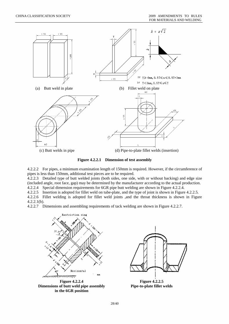
4.2.2 Type and dimension of test assembly 4.2.2.1 Dimensions for butt weld in plate, fillet weld on plate, butt weld in pipe and fillet weld on pipe are
shown in Figure 4.3.2.1(a), (b), (c) and (d) respectively.
CHINA CLASSIFICATION SOCIETY 2009 AMENDMENTS TO RULES
FOR MATERIALS AND WELDING
28/40
(a) Butt weld in plate (b) Fillet weld on plate
(c) Butt welds in pipe (d) Pipe-to-plate fillet welds (insertion)
Figure 4.2.2.1 Dimension of test assembly
4.2.2.2 For pipes, a minimum examination length of 150mm is required. However, if the circumference of
pipes is less than 150mm, additional test pieces are to be required.
4.2.2.3 Detailed type of butt welded joints (both sides, one side, with or without backing) and edge size
(included angle, root face, gap) may be determined by the manufacturer according to the actual production.
4.2.2.4 Special dimension requirements for 6GR pipe butt welding are shown in Figure 4.2.2.4.
4.2.2.5 Insertion is adopted for fillet weld on tube-plate, and the type of joint is shown in Figure 4.2.2.5.
4.2.2.6 Fillet welding is adopted for fillet weld joints ,and the throat thickness is shown in Figure
4.2.2.1(b).
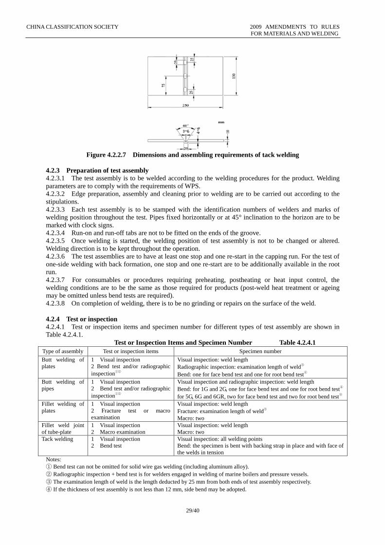
4.2.2.7 Dimensions and assembling requirements of tack welding are shown in Figure 4.2.2.7.
Figure 4.2.2.4 Figure 4.2.2.5
Dimensions of butt weld pipe assembly
in the 6GR position
Pipe-to-plate fillet welds
CHINA CLASSIFICATION SOCIETY 2009 AMENDMENTS TO RULES
FOR MATERIALS AND WELDING
29/40
Figure 4.2.2.7 Dimensions and assembling requirements of tack welding
4.2.3 Preparation of test assembly
4.2.3.1 The test assembly is to be welded according to the welding procedures for the product. Welding
parameters are to comply with the requirements of WPS.
4.2.3.2 Edge preparation, assembly and cleaning prior to welding are to be carried out according to the
stipulations.
4.2.3.3 Each test assembly is to be stamped with the identification numbers of welders and marks of
welding position throughout the test. Pipes fixed horizontally or at 45° inclination to the horizon are to be
marked with clock signs.
4.2.3.4 Run-on and run-off tabs are not to be fitted on the ends of the groove.
4.2.3.5 Once welding is started, the welding position of test assembly is not to be changed or altered.
Welding direction is to be kept throughout the operation.
4.2.3.6 The test assemblies are to have at least one stop and one re-start in the capping run. For the test of one-side welding with back formation, one stop and one re-start are to be additionally available in the root
run.
4.2.3.7 For consumables or procedures requiring preheating, postheating or heat input control, the
welding conditions are to be the same as those required for products (post-weld heat treatment or ageing
may be omitted unless bend tests are required).
4.2.3.8 On completion of welding, there is to be no grinding or repairs on the surface of the weld.
4.2.4 Test or inspection
4.2.4.1 Test or inspection items and specimen number for different types of test assembly are shown in
Table 4.2.4.1.
Test or Inspection Items and Specimen Number Table 4.2.4.1
Type of assembly Test or inspection items Specimen number
Butt welding of
plates
1 Visual inspection
2 Bend test and/or radiographic
inspection①②
Visual inspection: weld length
Radiographic inspection: examination length of weld③
Bend: one for face bend test and one for root bend test④
Butt welding of
pipes
1 Visual inspection
2 Bend test and/or radiographic
inspection①②
Visual inspection and radiographic inspection: weld length
Bend: for 1G and 2G, one for face bend test and one for root bend test④
for 5G, 6G and 6GR, two for face bend test and two for root bend test④
Fillet welding of
plates
1 Visual inspection
2 Fracture test or macro
examination
Visual inspection: weld length
Fracture: examination length of weld③
Macro: two
Fillet weld joint
of tube-plate
1 Visual inspection
2 Macro examination
Visual inspection: weld length
Macro: two
Tack welding 1 Visual inspection
2 Bend test
Visual inspection: all welding points
Bend: the specimen is bent with backing strap in place and with face of
the welds in tension
Notes:
① Bend test can not be omitted for solid wire gas welding (including aluminum alloy).
② Radiographic inspection + bend test is for welders engaged in welding of marine boilers and pressure vessels.
③ The examination length of weld is the length deducted by 25 mm from both ends of test assembly respectively.
④ If the thickness of test assembly is not less than 12 mm, side bend may be adopted.
CHINA CLASSIFICATION SOCIETY 2009 AMENDMENTS TO RULES
FOR MATERIALS AND WELDING
30/40
4.2.4.2 Before the visual inspection, the surface of welds is to be in the as-welded state and no machining
is to be made.
4.2.4.3 For radiographic inspection, reinforcement of weld and backing may not be removed.
4.2.4.4 Specimens are generally taken by machining in order not to affect the properties of the material. If
flame-cutting is applied, surplus metal not less than 5 mm from the line of cut is to be kept on both sides for
machining.
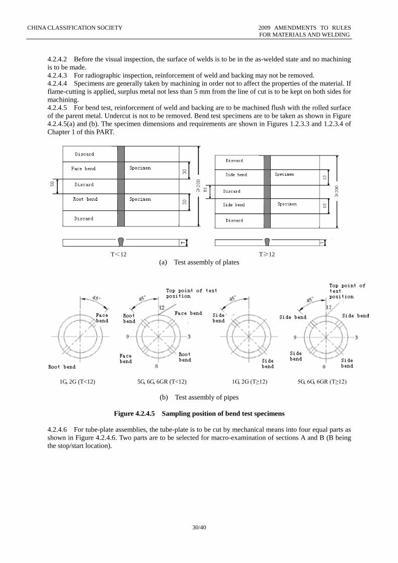
4.2.4.5 For bend test, reinforcement of weld and backing are to be machined flush with the rolled surface
of the parent metal. Undercut is not to be removed. Bend test specimens are to be taken as shown in Figure
4.2.4.5(a) and (b). The specimen dimensions and requirements are shown in Figures 1.2.3.3 and 1.2.3.4 of
Chapter 1 of this PART.
T<12 T≥12
(a) Test assembly of plates
1G, 2G (T<12) 5G, 6G, 6GR (T<12) 1G, 2G (T≥12) 5G, 6G, 6GR (T≥12)
(b) Test assembly of pipes
Figure 4.2.4.5 Sampling position of bend test specimens
4.2.4.6 For tube-plate assemblies, the tube-plate is to be cut by mechanical means into four equal parts as
shown in Figure 4.2.4.6. Two parts are to be selected for macro-examination of sections A and B (B being
the stop/start location).
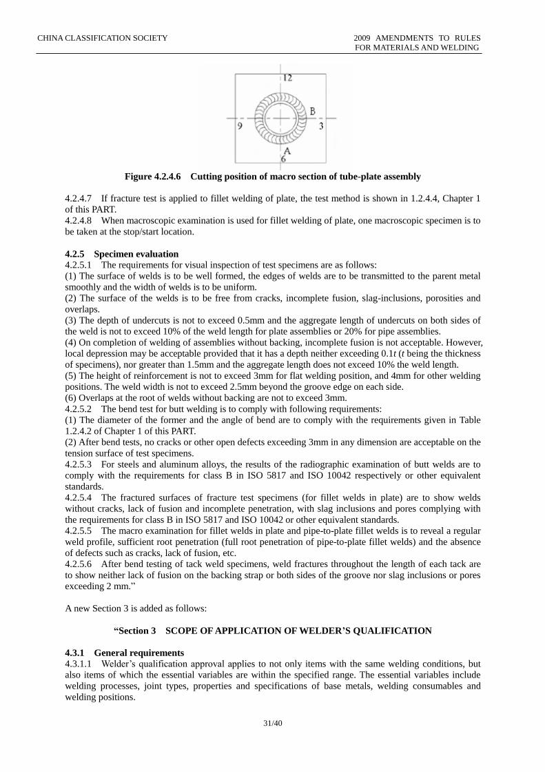
CHINA CLASSIFICATION SOCIETY 2009 AMENDMENTS TO RULES
FOR MATERIALS AND WELDING
31/40
Figure 4.2.4.6 Cutting position of macro section of tube-plate assembly
4.2.4.7 If fracture test is applied to fillet welding of plate, the test method is shown in 1.2.4.4, Chapter 1
of this PART.
4.2.4.8 When macroscopic examination is used for fillet welding of plate, one macroscopic specimen is to
be taken at the stop/start location.
4.2.5 Specimen evaluation
4.2.5.1 The requirements for visual inspection of test specimens are as follows:
(1) The surface of welds is to be well formed, the edges of welds are to be transmitted to the parent metal
smoothly and the width of welds is to be uniform.
(2) The surface of the welds is to be free from cracks, incomplete fusion, slag-inclusions, porosities and
overlaps.
(3) The depth of undercuts is not to exceed 0.5mm and the aggregate length of undercuts on both sides of
the weld is not to exceed 10% of the weld length for plate assemblies or 20% for pipe assemblies.
(4) On completion of welding of assemblies without backing, incomplete fusion is not acceptable. However,
local depression may be acceptable provided that it has a depth neither exceeding 0.1t (t being the thickness
of specimens), nor greater than 1.5mm and the aggregate length does not exceed 10% the weld length.
(5) The height of reinforcement is not to exceed 3mm for flat welding position, and 4mm for other welding
positions. The weld width is not to exceed 2.5mm beyond the groove edge on each side.
(6) Overlaps at the root of welds without backing are not to exceed 3mm.
4.2.5.2 The bend test for butt welding is to comply with following requirements:
(1) The diameter of the former and the angle of bend are to comply with the requirements given in Table
1.2.4.2 of Chapter 1 of this PART.
(2) After bend tests, no cracks or other open defects exceeding 3mm in any dimension are acceptable on the
tension surface of test specimens.
4.2.5.3 For steels and aluminum alloys, the results of the radiographic examination of butt welds are to
comply with the requirements for class B in ISO 5817 and ISO 10042 respectively or other equivalent
standards.
4.2.5.4 The fractured surfaces of fracture test specimens (for fillet welds in plate) are to show welds
without cracks, lack of fusion and incomplete penetration, with slag inclusions and pores complying with
the requirements for class B in ISO 5817 and ISO 10042 or other equivalent standards.
4.2.5.5 The macro examination for fillet welds in plate and pipe-to-plate fillet welds is to reveal a regular
weld profile, sufficient root penetration (full root penetration of pipe-to-plate fillet welds) and the absence
of defects such as cracks, lack of fusion, etc.
4.2.5.6 After bend testing of tack weld specimens, weld fractures throughout the length of each tack are
to show neither lack of fusion on the backing strap or both sides of the groove nor slag inclusions or pores
exceeding 2 mm.”
A new Section 3 is added as follows:
“Section 3 SCOPE OF APPLICATION OF WELDER’S QUALIFICATION
4.3.1 General requirements
4.3.1.1 Welder’s qualification approval applies to not only items with the same welding conditions, but
also items of which the essential variables are within the specified range. The essential variables include
welding processes, joint types, properties and specifications of base metals, welding consumables and
welding positions.
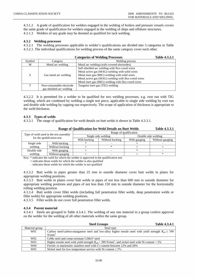
CHINA CLASSIFICATION SOCIETY 2009 AMENDMENTS TO RULES
FOR MATERIALS AND WELDING
32/40
4.3.1.2 A grade of qualification for welders engaged in the welding of boilers and pressure vessels covers
the same grade of qualification for welders engaged in the welding of ships and offshore structures.
4.3.1.3 Welders of any grade may be deemed as qualified for tack welding.
4.3.2 Welding processes
4.3.2.1 The welding processes applicable to welder’s qualifications are divided into 3 categories in Table
4.3.2.1. The individual qualifications for welding process of the same category cover each other.
Categories of Welding Processes Table 4.3.2.1 Symbol Category Welding process
M Metal arc welding Metal arc welding (with covered electrodes)
S Gas metal arc welding
Self-shielded arc welding with flux-cored wires
Metal active gas (MAG) welding with solid wires
Metal inert gas (MIG) welding with solid wires
Metal active gas (MAG) welding with flux-cored wires
Metal inert gas (MIG) welding with flux-cored wires
T Non-consumable electrode
gas shielded arc welding
Tungsten inert gas (TIG) welding
4.3.2.2 It is permitted for a welder to be qualified for two welding processes, e.g. root run with TIG
welding, which are combined by welding a single test piece, applicable to single side welding by root run
and double side welding by capping run respectively. The scope of application of thickness is appropriate to
the weld thickness.
4.3.3 Types of welds
4.3.3.1 The range of qualification for weld details on butt welds is shown in Table 4.3.3.1.
Range of Qualification for Weld Details on Butt Welds Table 4.3.3.1
Type of weld used in the test assembly
for the qualification test
Range of qualification Single side welding Double side welding
With backing Without backing With gauging Without gauging
Single side
welding
With backing * – × –
Without backing × * × ×
Double side
welding
With gauging × – * –
Without gauging × – × *
Key: * indicates the weld for which the welder is approved in the qualification test
× indicates those welds for which the welder is also qualified
– indicates those welds for which the welder is not qualified
4.3.3.2 Butt welds in pipes greater than 25 mm in outside diameter cover butt welds in plates for
appropriate welding positions.
4.3.3.3 Butt welds in plates cover butt welds in pipes of not less than 600 mm in outside diameter for
appropriate welding positions and pipes of not less than 150 mm in outside diameter for the horizontally
rolling welding position.
4.3.3.4 Butt welds cover fillet welds (including full penetration fillet welds, deep penetration welds or
fillet welds) for appropriate welding positions.
4.3.3.5 Fillet welds do not cover full penetration fillet welds.
4.3.4 Parent material
4.3.4.1 Steels are grouped in Table 4.3.4.1. The welding of any one material in a group confers approval
on the welder for the welding of all other materials within the same group.
Steel Groups Table 4.3.4.1
Material group Steel type
W01 Carbon steel/carbon-manganese steel and low-alloy higher tensile steel with yield strength ReH ≤ 390
N/mm2
W02 CrMo steel and creep-resistant CrMoV steel
W03 Higher tensile steel with yield strength ReH > 390 N/mm2, and nickel steel with Ni content < 5%
W04 Ferritic or martensitic stainless steel with Cr content between 12% and 20%
W05 Nickel steel for low temperature service with Ni content ≥ 5%
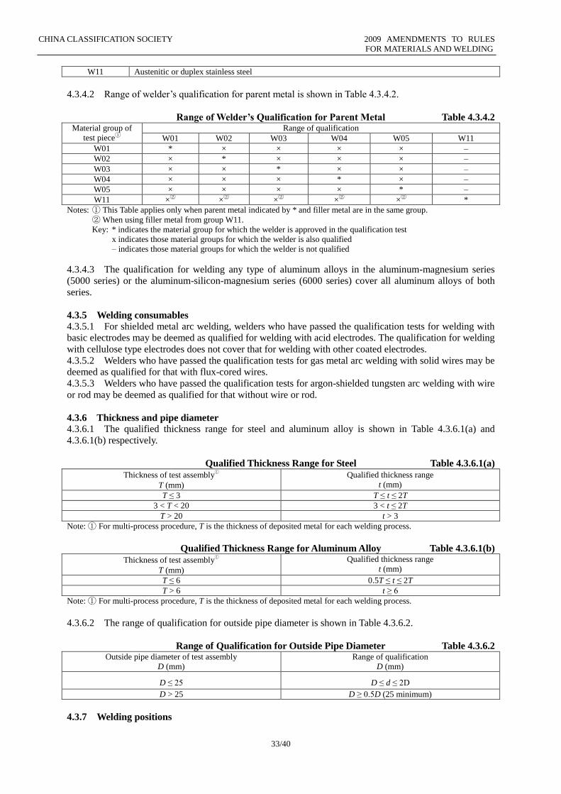
CHINA CLASSIFICATION SOCIETY 2009 AMENDMENTS TO RULES
FOR MATERIALS AND WELDING
33/40
W11 Austenitic or duplex stainless steel
4.3.4.2 Range of welder’s qualification for parent metal is shown in Table 4.3.4.2.
Range of Welder’s Qualification for Parent Metal Table 4.3.4.2
Material group of
test piece①
Range of qualification
W01 W02 W03 W04 W05 W11
W01 * × × × × –
W02 × * × × × –
W03 × × * × × –
W04 × × × * × –
W05 × × × × * –
W11 ×② ×② ×② ×② ×② *
Notes: ① This Table applies only when parent metal indicated by * and filler metal are in the same group.
② When using filler metal from group W11.
Key: * indicates the material group for which the welder is approved in the qualification test
x indicates those material groups for which the welder is also qualified
– indicates those material groups for which the welder is not qualified
4.3.4.3 The qualification for welding any type of aluminum alloys in the aluminum-magnesium series
(5000 series) or the aluminum-silicon-magnesium series (6000 series) cover all aluminum alloys of both
series.
4.3.5 Welding consumables
4.3.5.1 For shielded metal arc welding, welders who have passed the qualification tests for welding with
basic electrodes may be deemed as qualified for welding with acid electrodes. The qualification for welding
with cellulose type electrodes does not cover that for welding with other coated electrodes.
4.3.5.2 Welders who have passed the qualification tests for gas metal arc welding with solid wires may be
deemed as qualified for that with flux-cored wires.
4.3.5.3 Welders who have passed the qualification tests for argon-shielded tungsten arc welding with wire
or rod may be deemed as qualified for that without wire or rod.
4.3.6 Thickness and pipe diameter 4.3.6.1 The qualified thickness range for steel and aluminum alloy is shown in Table 4.3.6.1(a) and
4.3.6.1(b) respectively.
Qualified Thickness Range for Steel Table 4.3.6.1(a) Thickness of test assembly
①
T (mm)
Qualified thickness range
t (mm)
T ≤ 3 T ≤ t ≤ 2T
3 < T < 20 3 < t ≤ 2T
T > 20 t > 3
Note: ① For multi-process procedure, T is the thickness of deposited metal for each welding process.
Qualified Thickness Range for Aluminum Alloy Table 4.3.6.1(b) Thickness of test assembly
①
T (mm)
Qualified thickness range
t (mm)
T ≤ 6 0.5T ≤ t ≤ 2T
T > 6 t ≥ 6
Note: ① For multi-process procedure, T is the thickness of deposited metal for each welding process.
4.3.6.2 The range of qualification for outside pipe diameter is shown in Table 4.3.6.2.
Range of Qualification for Outside Pipe Diameter Table 4.3.6.2 Outside pipe diameter of test assembly
D (mm)
Range of qualification
D (mm)
D ≤ 25 D ≤ d ≤ 2D
D > 25 D ≥ 0.5D (25 minimum)
4.3.7 Welding positions
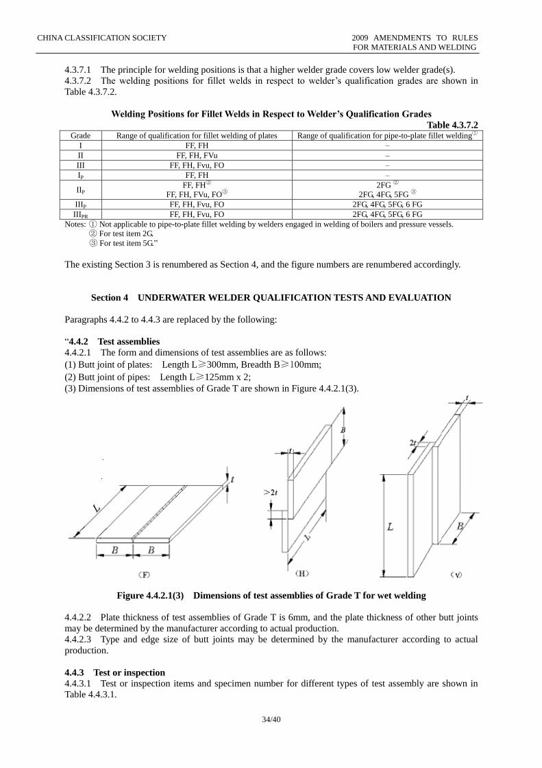
CHINA CLASSIFICATION SOCIETY 2009 AMENDMENTS TO RULES
FOR MATERIALS AND WELDING
34/40
4.3.7.1 The principle for welding positions is that a higher welder grade covers low welder grade(s).
4.3.7.2 The welding positions for fillet welds in respect to welder’s qualification grades are shown in
Table 4.3.7.2.
Welding Positions for Fillet Welds in Respect to Welder’s Qualification Grades
Table 4.3.7.2 Grade Range of qualification for fillet welding of plates Range of qualification for pipe-to-plate fillet welding①
I FF, FH –
II FF, FH, FVu –
III FF, FH, Fvu, FO –
IP FF, FH –
IIP FF, FH②
FF, FH, FVu, FO③
2FG ②
2FG, 4FG, 5FG ③
IIIP FF, FH, Fvu, FO 2FG, 4FG, 5FG, 6 FG
IIIPR FF, FH, Fvu, FO 2FG, 4FG, 5FG, 6 FG
Notes: ① Not applicable to pipe-to-plate fillet welding by welders engaged in welding of boilers and pressure vessels.
② For test item 2G.
③ For test item 5G.”
The existing Section 3 is renumbered as Section 4, and the figure numbers are renumbered accordingly.
Section 4 UNDERWATER WELDER QUALIFICATION TESTS AND EVALUATION
Paragraphs 4.4.2 to 4.4.3 are replaced by the following:
“4.4.2 Test assemblies
4.4.2.1 The form and dimensions of test assemblies are as follows:
(1) Butt joint of plates: Length L≥300mm, Breadth B≥100mm;
(2) Butt joint of pipes: Length L≥125mm x 2;
(3) Dimensions of test assemblies of Grade T are shown in Figure 4.4.2.1(3).
Figure 4.4.2.1(3) Dimensions of test assemblies of Grade T for wet welding
4.4.2.2 Plate thickness of test assemblies of Grade T is 6mm, and the plate thickness of other butt joints
may be determined by the manufacturer according to actual production.
4.4.2.3 Type and edge size of butt joints may be determined by the manufacturer according to actual
production.
4.4.3 Test or inspection
4.4.3.1 Test or inspection items and specimen number for different types of test assembly are shown in
Table 4.4.3.1.
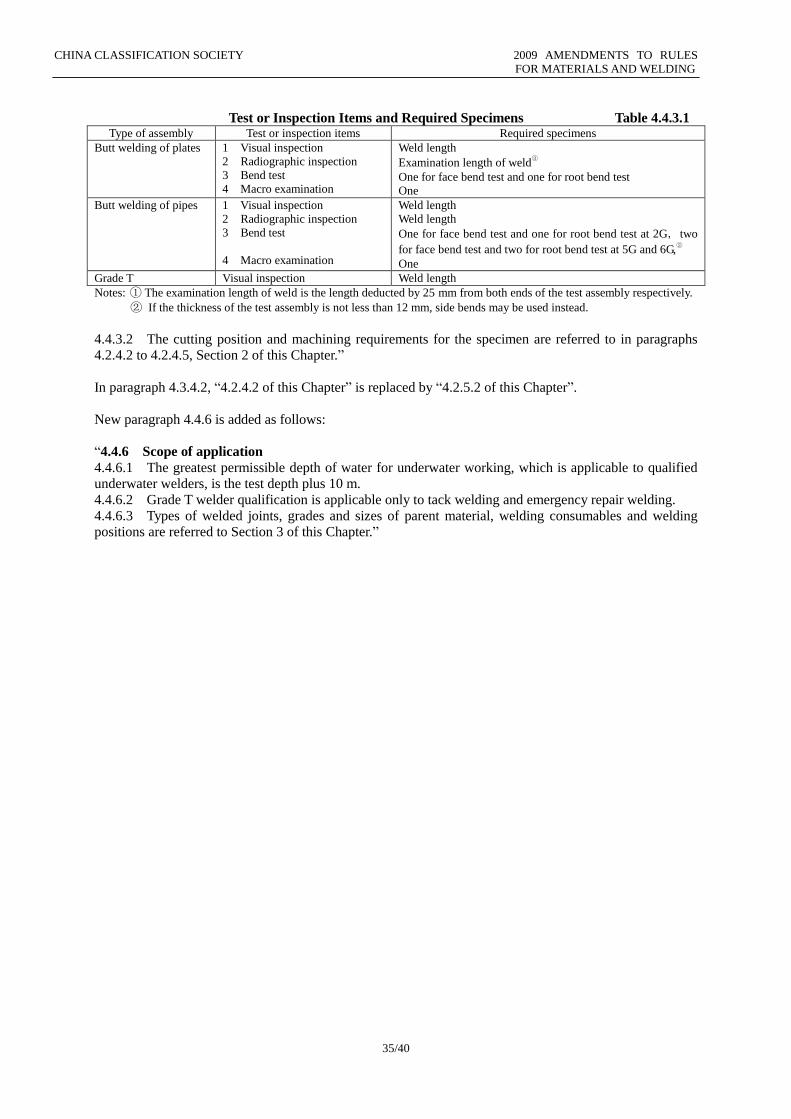
CHINA CLASSIFICATION SOCIETY 2009 AMENDMENTS TO RULES
FOR MATERIALS AND WELDING
35/40
Test or Inspection Items and Required Specimens Table 4.4.3.1 Type of assembly Test or inspection items Required specimens
Butt welding of plates 1 Visual inspection
2 Radiographic inspection
3 Bend test
4 Macro examination
Weld length
Examination length of weld③
One for face bend test and one for root bend test
One
Butt welding of pipes 1 Visual inspection
2 Radiographic inspection
3 Bend test
4 Macro examination
Weld length
Weld length
One for face bend test and one for root bend test at 2G, two
for face bend test and two for root bend test at 5G and 6G,②
One
Grade T Visual inspection Weld length
Notes: ① The examination length of weld is the length deducted by 25 mm from both ends of the test assembly respectively.
② If the thickness of the test assembly is not less than 12 mm, side bends may be used instead.
4.4.3.2 The cutting position and machining requirements for the specimen are referred to in paragraphs
4.2.4.2 to 4.2.4.5, Section 2 of this Chapter.”
In paragraph 4.3.4.2, “4.2.4.2 of this Chapter” is replaced by “4.2.5.2 of this Chapter”.
New paragraph 4.4.6 is added as follows:
“4.4.6 Scope of application
4.4.6.1 The greatest permissible depth of water for underwater working, which is applicable to qualified
underwater welders, is the test depth plus 10 m.
4.4.6.2 Grade T welder qualification is applicable only to tack welding and emergency repair welding.
4.4.6.3 Types of welded joints, grades and sizes of parent material, welding consumables and welding
positions are referred to Section 3 of this Chapter.”
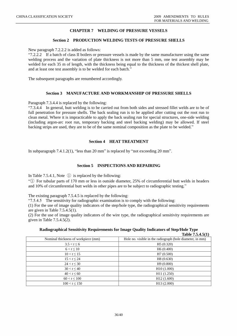
CHINA CLASSIFICATION SOCIETY 2009 AMENDMENTS TO RULES
FOR MATERIALS AND WELDING
36/40
CHAPTER 7 WELDING OF PRESSURE VESSELS
Section 2 PRODUCTION WELDING TESTS OF PRESSURE SHELLS
New paragraph 7.2.2.2 is added as follows:
“7.2.2.2 If a batch of class II boilers or pressure vessels is made by the same manufacturer using the same
welding process and the variation of plate thickness is not more than 5 mm, one test assembly may be
welded for each 35 m of length, with the thickness being equal to the thickness of the thickest shell plate,
and at least one test assembly is to be welded for each batch.”
The subsequent paragraphs are renumbered accordingly.
Section 3 MANUFACTURE AND WORKMANSHIP OF PRESSURE SHELLS
Paragraph 7.3.4.4 is replaced by the following:
“7.3.4.4 In general, butt welding is to be carried out from both sides and stressed fillet welds are to be of
full penetration for pressure shells. The back sealing run is to be applied after cutting out the root run to
clean metal. Where it is impracticable to apply the back sealing run for special structures, one-side welding
(including argon-arc root run, temporary backing and steel backing welding) may be allowed. If steel
backing strips are used, they are to be of the same nominal composition as the plate to be welded.”
Section 4 HEAT TREATMENT
In subparagraph 7.4.1.2(1), “less than 20 mm” is replaced by “not exceeding 20 mm”.
Section 5 INSPECTIONS AND REPAIRING
In Table 7.5.4.1, Note ① is replaced by the following:
“① For tubular parts of 170 mm or less in outside diameter, 25% of circumferential butt welds in headers
and 10% of circumferential butt welds in other pipes are to be subject to radiographic testing.”
The existing paragraph 7.5.4.5 is replaced by the following:
“7.5.4.5 The sensitivity for radiographic examination is to comply with the following:
(1) For the use of image quality indicators of the step/hole type, the radiographical sensitivity requirements
are given in Table 7.5.4.5(1).
(2) For the use of image quality indicators of the wire type, the radiographical sensitivity requirements are
given in Table 7.5.4.5(2).
Radiographical Sensitivity Requirements for Image Quality Indicators of Step/Hole Type
Table 7.5.4.5(1) Nominal thickness of workpiece (mm) Hole no. visible in the radiograph (hole diameter, in mm)
3.5 < t ≤ 6 H5 (0.320)
6 < t ≤ 10 H6 (0.400)
10 < t ≤ 15 H7 (0.500)
15 < t ≤ 24 H8 (0.630)
24 < t ≤ 30 H9 (0.800)
30 < t ≤ 40 H10 (1.000)
40 < t ≤ 60 H11 (1.250)
60 < t ≤ 100 H12 (1.600)
100 < t ≤ 150 H13 (2.000)
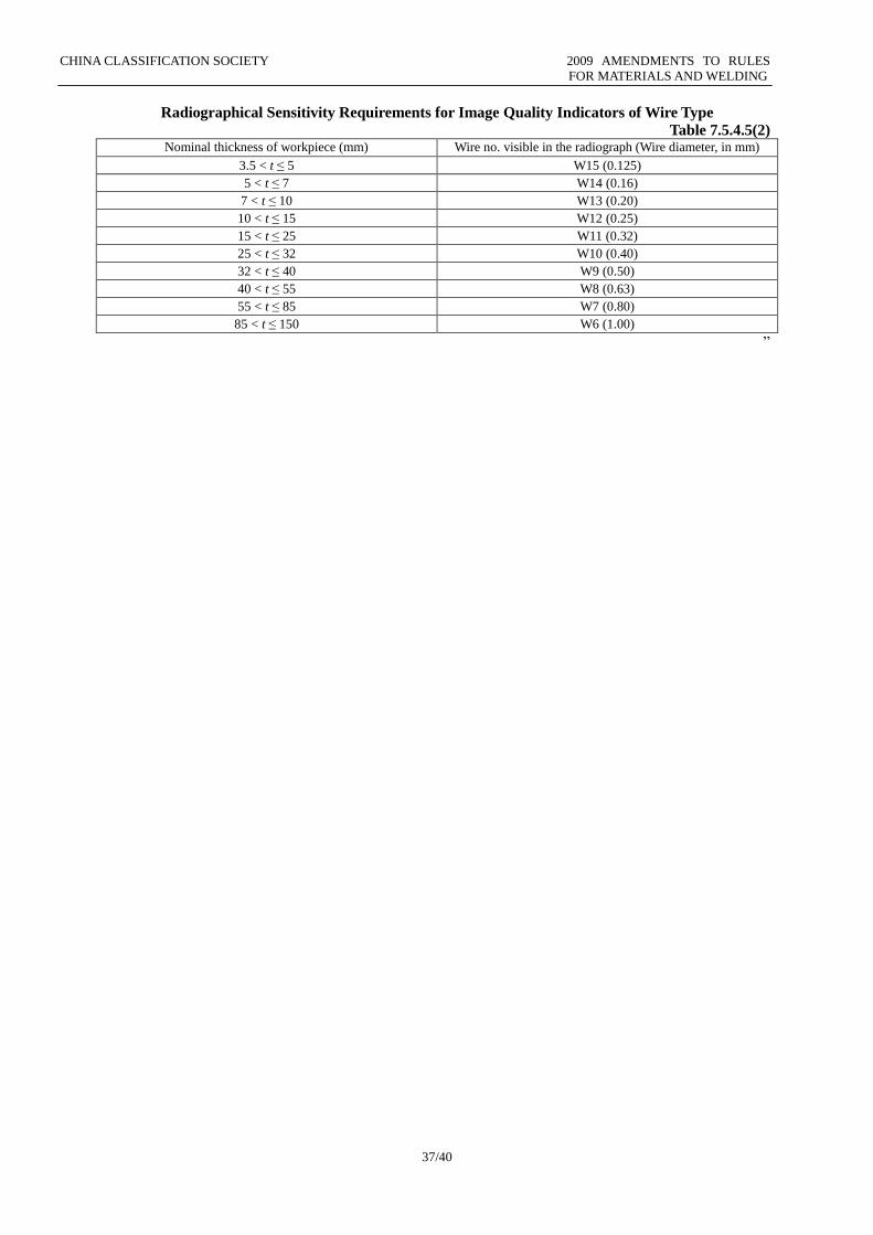
CHINA CLASSIFICATION SOCIETY 2009 AMENDMENTS TO RULES
FOR MATERIALS AND WELDING
37/40
Radiographical Sensitivity Requirements for Image Quality Indicators of Wire Type
Table 7.5.4.5(2) Nominal thickness of workpiece (mm) Wire no. visible in the radiograph (Wire diameter, in mm)
3.5 < t ≤ 5 W15 (0.125)
5 < t ≤ 7 W14 (0.16)
7 < t ≤ 10 W13 (0.20)
10 < t ≤ 15 W12 (0.25)
15 < t ≤ 25 W11 (0.32)
25 < t ≤ 32 W10 (0.40)
32 < t ≤ 40 W9 (0.50)
40 < t ≤ 55 W8 (0.63)
55 < t ≤ 85 W7 (0.80)
85 < t ≤ 150 W6 (1.00)
”
CHINA CLASSIFICATION SOCIETY 2009 AMENDMENTS TO RULES
FOR MATERIALS AND WELDING
38/40
CHAPTER 9 WELDING OF PRESSURE PIPES
Section 1 GENERAL PROVISIONS
New paragraph 9.1.2 is added as follows:
“9.1.2 Material
9.1.2.1 The following requirements apply to the fabrication of Classes I and II piping systems operating
at ambient or high temperature and made of steel of the types given hereunder:
(1) carbon and carbon-manganese steels having minimum tensile strength (Rm) 320, 360, 410, 460 and 490
N/mm2;
(2) low alloy carbon-molybdenum, chromium-molybdenum, chromium-molybdenum-vanadium steels
having chemical composition 0.3Mo, 1Cr-0.5Mo, 2.25Cr-1Mo, 0.5Cr-0.5Mo-0.25V.
9.1.2.2 These requirements may be applied also to the Class III piping systems and to repair welding of
pipelines.
9.1.2.3 Piping systems operating at temperatures lower than -40℃ will be given special consideration by
CCS.”
The subsequent paragraphs are renumbered accordingly.
Section 2 WELDING OF PIPE JOINTS
New paragraphs 9.2.1.3 and 9.2.1.4 are added as follows:
“9.2.1.3 The preparation of the edges is to be preferably carried out by mechanical means. When flame
cutting is used, care is to be taken to remove the oxide scales and any notch due to irregular cutting by
matching grinding or chipping back to sound metal.
9.2.1.4 Welding is to be done according to applicable requirements. The weld preparation and the welded
joint are to be inspected as may be necessary in the course of fabrication and after completion of the
welding heat treatment.”
New paragraph 9.2.2.4 is added as follows:
“9.2.2.4 Tack welds are to be made with an electrode suitable for the base metal; tack welds which form
part of the finished weld are to be made using approved procedures. When welding materials require
preheating, the same preheating is to be applied during tack welding.”
The subsequent paragraphs are renumbered accordingly.
Section 3 INSPECTION OF WELDING QUALITY
Paragraph 9.3.3 is replaced by the following:
“9.3.3 Non-destructive examination
9.3.3.1 All butt joints of Class I pipes having an external diameter greater than 75 mm are to be subjected
to radiographic or gammagraphic examination.
9.3.3.2 10% of butt joints of Class II pipes having an external diameter greater than 100 mm and butt
joints of Class I pipes having an external diameter equal to or less than 75 mm are to be subjected to
radiographic or gammagraphic examination.
9.3.3.3 An approved ultrasonic testing procedure may be accepted in lieu of radiographic testing when the
conditions are such that a comparable level of weld quality is assured.
9.3.3.4 Fillet welds of flange pipe connections are to be examined by the magnetic particle method or by
other appropriate non-destructive methods, in case of Class I pipes. In other cases, magnetic particle
examination or equivalent non-destructive testing may be required for fillet welds depending upon the
material, wall thickness and outside diameter of pipes and the nature of medium therein.
9.3.3.5 Ultrasonic examination in addition to the above non-destructive testing may be required in special
cases.
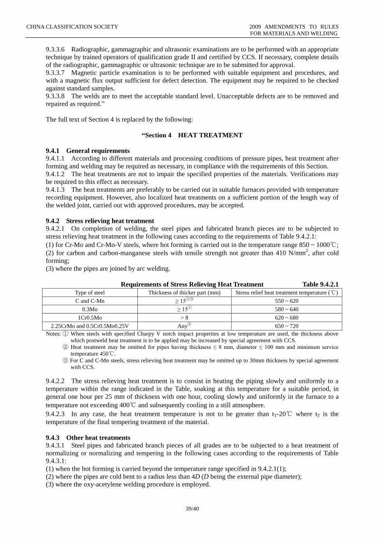
CHINA CLASSIFICATION SOCIETY 2009 AMENDMENTS TO RULES
FOR MATERIALS AND WELDING
39/40
9.3.3.6 Radiographic, gammagraphic and ultrasonic examinations are to be performed with an appropriate
technique by trained operators of qualification grade II and certified by CCS. If necessary, complete details
of the radiographic, gammagraphic or ultrasonic technique are to be submitted for approval.
9.3.3.7 Magnetic particle examination is to be performed with suitable equipment and procedures, and
with a magnetic flux output sufficient for defect detection. The equipment may be required to be checked
against standard samples.
9.3.3.8 The welds are to meet the acceptable standard level. Unacceptable defects are to be removed and
repaired as required.”
The full text of Section 4 is replaced by the following:
“Section 4 HEAT TREATMENT
9.4.1 General requirements 9.4.1.1 According to different materials and processing conditions of pressure pipes, heat treatment after
forming and welding may be required as necessary, in compliance with the requirements of this Section.
9.4.1.2 The heat treatments are not to impair the specified properties of the materials. Verifications may
be required to this effect as necessary.
9.4.1.3 The heat treatments are preferably to be carried out in suitable furnaces provided with temperature
recording equipment. However, also localized heat treatments on a sufficient portion of the length way of
the welded joint, carried out with approved procedures, may be accepted.
9.4.2 Stress relieving heat treatment
9.4.2.1 On completion of welding, the steel pipes and fabricated branch pieces are to be subjected to
stress relieving heat treatment in the following cases according to the requirements of Table 9.4.2.1:
(1) for Cr-Mo and Cr-Mo-V steels, where hot forming is carried out in the temperature range 850 ~ 1000℃;
(2) for carbon and carbon-manganese steels with tensile strength not greater than 410 N/mm2, after cold
forming;
(3) where the pipes are joined by arc welding.
Requirements of Stress Relieving Heat Treatment Table 9.4.2.1
Type of steel Thickness of thicker part (mm) Stress relief heat treatment temperature (℃)
C and C-Mn ≥ 15①③ 550 ~ 620
0.3Mo ≥ 15① 580 ~ 640
1Cr0.5Mo > 8 620 ~ 680
2.25CrMo and 0.5Cr0.5Mo0.25V Any② 650 ~ 720
Notes: ① When steels with specified Charpy V notch impact properties at low temperature are used, the thickness above
which postweld heat treatment is to be applied may be increased by special agreement with CCS.
② Heat treatment may be omitted for pipes having thickness ≤ 8 mm, diameter ≤ 100 mm and minimum service
temperature 450℃.
③ For C and C-Mn steels, stress relieving heat treatment may be omitted up to 30mm thickness by special agreement
with CCS.
9.4.2.2 The stress relieving heat treatment is to consist in heating the piping slowly and uniformly to a
temperature within the range indicated in the Table, soaking at this temperature for a suitable period, in
general one hour per 25 mm of thickness with one hour, cooling slowly and uniformly in the furnace to a
temperature not exceeding 400℃ and subsequently cooling in a still atmosphere.
9.4.2.3 In any case, the heat treatment temperature is not to be greater than tT-20℃ where tT is the
temperature of the final tempering treatment of the material.
9.4.3 Other heat treatments
9.4.3.1 Steel pipes and fabricated branch pieces of all grades are to be subjected to a heat treatment of
normalizing or normalizing and tempering in the following cases according to the requirements of Table
9.4.3.1:
(1) when the hot forming is carried beyond the temperature range specified in 9.4.2.1(1);
(2) where the pipes are cold bent to a radius less than 4D (D being the external pipe diameter);
(3) where the oxy-acetylene welding procedure is employed.
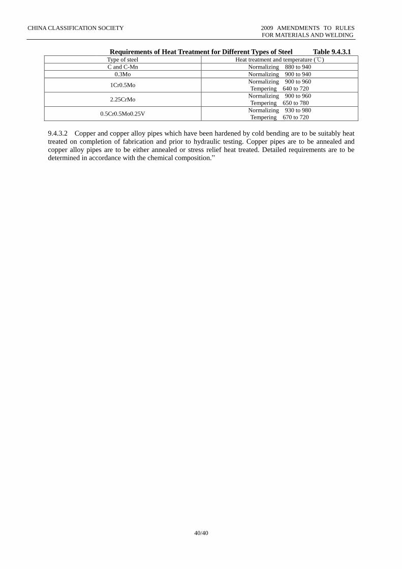
CHINA CLASSIFICATION SOCIETY 2009 AMENDMENTS TO RULES
FOR MATERIALS AND WELDING
40/40
Requirements of Heat Treatment for Different Types of Steel Table 9.4.3.1 Type of steel Heat treatment and temperature (℃)
C and C-Mn Normalizing 880 to 940
0.3Mo Normalizing 900 to 940
1Cr0.5Mo Normalizing 900 to 960
Tempering 640 to 720
2.25CrMo Normalizing 900 to 960
Tempering 650 to 780
0.5Cr0.5Mo0.25V Normalizing 930 to 980
Tempering 670 to 720
9.4.3.2 Copper and copper alloy pipes which have been hardened by cold bending are to be suitably heat
treated on completion of fabrication and prior to hydraulic testing. Copper pipes are to be annealed and
copper alloy pipes are to be either annealed or stress relief heat treated. Detailed requirements are to be
determined in accordance with the chemical composition.”