ccna study notes - reelreality.com study notes 1. identify and describe the functions of each of the...
TRANSCRIPT
CCNA Study Notes
1. Identify and describe the functions of each of the seven layers of the OSI reference model.
Physical Layer
The physical layer defines the electrical, mechanical, procedural, and functional specifications for activating, maintaining, and deactivating the physical link between communicating network systems. Physical layer specifications define such characteristics as voltage levels, timing of voltage changes, physical data rates, maximum transmission distances, and the physical connectors to be used.
Data Link Layer
The data link layer provides reliable transit of data across a physical network link. Different data link layer specifications define different network and protocol characteristics, including the following:
Physical addressing -- Physical addressing (as opposed to network addressing) defines how devices are addressed at the data link layer.
Network topology -- Data link layer specifications often define how devices are to be physically connected (such as in a bus or a ring topology).
Error notification -- Error notification involves alerting upper layer protocols that a transmission error has occurred.
Sequencing of frames -- Sequencing of data frames involves the reordering of frames that are transmitted out of sequence.
Flow control -- Flow control involves moderating the transmission of data so that the receiving device is not overwhelmed with more traffic than it can handle at one time.
The Institute of Electrical and Electronics Engineers (IEEE) has subdivided the data link layer into two sublayers: Logical Link Control (LLC) and Media Access Control (MAC).
Network Layer
The network layer provides routing and related functions that allow multiple data links to be combined into an internetwork. This is accomplished by the logical addressing (as opposed to the physical addressing) of devices. The network layer supports both connection-oriented and connectionless service from higher-layer protocols.

Transport Layer
The transport layer implements reliable internetwork data transport services that are transparent to upper layers. Transport layer functions typically include the following:
Flow control -- Flow control manages data transmission between devices so that the transmitting device does not send more data than the receiving device can process.
Multiplexing -- Multiplexing allows data from several applications to be transmitted onto a single physical link.
Virtual circuit management -- Virtual circuits are established, maintained, and terminated by the transport layer.
Error checking and recovery -- Error checking involves various mechanisms for detecting transmission errors. Error recovery involves taking an action (such as requesting that data be retransmitted) to resolve any errors that occur.
Some examples of transport layer implementations follow:
Transmission Control Protocol (TCP), Name Binding Protocol (NBP), OSI transport protocols
Session Layer
The session layer establishes, manages, and terminates communication sessions between presentation layer entities. Communication sessions consist of service requests and service responses that occur between applications located in different network devices. These requests and responses are coordinated by protocols implemented at the session layer. Some examples of session layer implementations follow:
Apple ZIP, DEC SCP, NFS, SQL, RPC, X Windows, ASP
Presentation Layer
The presentation layer provides a variety of coding and conversion functions that are applied to application layer data. These functions ensure that information sent from the application layer of one system will be readable by the application layer of another system. Some examples of presentation layer coding and conversion schemes follow:
Common data representation formats -- The use of standard image, sound, and video formats allow the interchange of application data between different types of computer systems.
Conversion of character representation formats -- Conversion schemes are used to exchange information with systems using different text and data representations (such as EBCDIC and ASCII).
Common data compression schemes -- The use of standard data compression schemes allows data that is compressed at the source device to be properly decompressed at the destination.
Common data encryption schemes -- The use of standard data encryption schemes allows data encrypted at the source device to be properly unencrypted at the destination.
Presentation layer implementations are not typically associated with a particular protocol stack. Some well known standards follow:
Data: ASCII, EBCDIC, Encryption
Visual Imaging: PICT, TIFF, GIF, JPEG
Video: MIDI, MPEG, QuickTime
Application Layer
The application layer interacts with software applications that implement a communicating component. Application layer functions typically include the following:
Identifying communication partners -- The application layer identifies and determines the availability of communication partners for an application with data to transmit.
Determining resource availability -- The application layer must determine whether sufficient network resources for the requested communication are available.
Synchronizing communication -- Communication between applications requires cooperation that is managed by the application layer.
The application layer is the OSI layer closest to the end user. That is, both the OSI application layer and the user interact directly with the software application. Some examples of application layer implementations follow:
TCP/IP applications -- TCP/IP applications are protocols in the Internet Protocol suite, such as Telnet, File Transfer Protocol (FTP), and Simple Mail Transfer Protocol (SMTP).
OSI applications -- OSI applications are protocols in the OSI suite such as File Transfer, Access, and Management (FTAM), Virtual Terminal Protocol (VTP), and Common Management Information Protocol (CMIP).
2. Describe connection-oriented network service and connectionless network service and identify the key differences between them.
Connection-Oriented Network Service
Connection-oriented service involves three phases:
Connection establishment -- During the connection establishment phase, a single path between the source and destination systems is determined. Network resources are typically reserved at this time to ensure a consistent grade of service (such as a guaranteed throughput rate).
Data transfer -- During the data transfer phase, data is transmitted sequentially over the path that has been established. Data always arrives at the destination system in the order in which it was sent.
Connection termination -- During the connection termination phase, an established connection that is no longer needed is terminated. Further communication between the source and destination systems requires that a new connection be established.
Connection-oriented service has two significant disadvantages as compared to connectionless network service:
Static path selection -- Because all traffic must travel along the same static path, a failure anywhere along that path causes the connection to fail.
Static reservation of network resources -- A guaranteed rate of throughput requires the commitment of resources that cannot be shared by other network users. Unless full, uninterrupted throughput is required for the communication, bandwidth is not used efficiently.
Connection-oriented services are useful for transmitting data from applications that are intolerant of delays and packet re-sequencing. Voice and video applications are typically based on connection-oriented services.
Connectionless Network Service
Connectionless network service does not predetermine the path from the source to the destination system, nor are packet sequencing, data throughput, and other network resources guaranteed. Each packet must be completely addressed because different paths through the network might be selected for different packets, based on a variety of influences. Each packet is transmitted independently by the source system and is handled independently by intermediate network devices. Connectionless service offers two important advantages over connection-oriented service:
Dynamic path selection -- Because paths are selected on a packet-by-packet basis, traffic can be routed around network failures.
Dynamic bandwidth allocation -- Bandwidth is used more efficiently because network resources are not allocated bandwidth that they are not going to use.
Connectionless services are useful for transmitting data from applications that can tolerate some delay and re-sequencing. Data-based applications are typically based on connectionless service.
3. Describe data link addresses and network addresses and identify the key differences between them.
Data Link Layer Addresses
A data link layer address uniquely identifies each physical network connection of a network device. Data link addresses are sometimes referred to as physical or hardware addresses. Data link addresses usually exist within a flat address space and have a pre-established and typically

fixed relationship to a specific device. End systems typically have only one physical network connection, and thus have only one data link address. Routers and other internetworking devices typically have multiple physical network connections. They therefore have multiple data link addresses.
Network Layer Addresses
A network layer address identifies an entity at the network layer of the OSI reference model. Network addresses usually exist within a hierarchical address space. They are sometimes called virtual or logical addresses. The relationship of a network address with a device is logical and unfixed. It is typically based either on physical network characteristics (the device is on a particular network segment) or on groupings that have no physical basis (the device is part of an AppleTalk zone). End systems require one network layer address for each network layer protocol they support. (This assumes that the device has only one physical network connection.) Routers and other internetworking devices require one network layer address per physical network connection for each network layer protocol supported. For example, a router with three interfaces, each running AppleTalk, TCP/IP, and OSI, must have three network layer addresses for each interface. The router therefore has nine network layer addresses.
4. Define and describe the function of a MAC address.
Media Access Control (MAC) addresses are a subset of data link layer addresses. MAC addresses identify network entities in LANs implementing the IEEE MAC sublayer of the data link layer. Like most data link addresses, MAC addresses are unique for each LAN interface. MAC addresses are 48 bits in length and are expressed as 12 hexadecimal digits: The first 6 hexadecimal digits are the manufacturer identification (or vendor code), called the Organizational Unique Identifier (OUI). These 6 digits are administered by the IEEE. The last 6 hexadecimal digits are the interface serial number or another value administered by the specific vendor. MAC addresses are sometimes called burned-in addresses (BIAs) because they are burned into read-only memory (ROM) and copied into random-access memory (RAM) when the interface card initializes.
5. Define flow control and describe the three basic methods used in networking.
Flow control is a function that prevents network congestion by ensuring that transmitting devices do not overwhelm receiving devices with data. There are a number of possible causes of network congestion. For example, a high-speed computer might generate traffic faster than the network can transfer it, or faster than the destination device can receive and process it. There are three commonly used methods for handling network congestion:
Buffering - Buffering is used by network devices to temporarily store bursts of excess data in memory until they can be processed. Occasional data bursts are easily handled by buffering. However, excess data bursts can exhaust memory, forcing the device to discard any additional datagrams that arrive.
Source quench messages - Source quench messages are used by receiving devices to help prevent their buffers from overflowing. The receiving device sends source quench messages to request that the source reduce its current rate of data transmission, as follows:

1. The receiving device begins discarding received data due to overflowing buffers.
2. The receiving device begins sending source quench messages to the transmitting device, at the rate of one message for each packet dropped.
3. The source device receives the source quench messages and lowers the data rate until it stops receiving the messages.
4. The source device then gradually increases the data rate as long as no further source quench requests are received.
Windowing - Windowing is a flow-control scheme in which the source device requires an acknowledgement from the destination after a certain number of packets have been transmitted. With a window size of three, the source requires an acknowledgment after sending three packets, as follows:
1. The source device sends three packets to the destination device.
2. After receiving the three packets, the destination device sends an acknowledgment to the source.
3. The source receives the acknowledgment and sends three more packets.
4. If the destination does not receive one or more of the packets for some reason (such as overflowing buffers), it does not receive enough packets to send an acknowledgment. The source, not receiving an acknowledgment, retransmits the packets at a reduced transmission rate.
6. Differentiate between the following WAN services: X.25 / LAPB, Frame Relay, ISDN / LAPD, SDLC. HDLC, PPP and DDR.
X.25 - ITU-T standard that defines how connections between DTE and DCE are maintained for remote terminal access and computer communications in PDNs. X.25 specifies LAPB, a data link layer protocol, and PLP, a network layer protocol. Frame Relay has to some degree superseded X.25.
Frame Relay - Industry-standard, switched data link layer protocol that handles multiple virtual circuits using HDLC encapsulation between connected devices. Frame Relay is more efficient than X.25, the protocol for which it is generally considered a replacement.
ISDN - Integrated Services Digital Network. Communication protocol, offered by telephone companies, that permits telephone networks to carry data, voice, and other source traffic.
SDLC - Synchronous Data Link Control. SNA data link layer communications protocol. SDLC is a bit-oriented, full-duplex serial protocol that has spawned numerous similar protocols, including HDLC and LAPB.
HDLC - High-Level Data Link Control. Bit-oriented synchronous data link layer protocol developed by ISO. Derived from SDLC, HDLC specifies a data encapsulation method on synchronous serial links using frame characters and checksums.
PPP - Point-to-Point Protocol. A successor to SLIP, PPP provides router-to-router and host-to-network connections over synchronous and asynchronous circuits.
DDR - dial-on-demand routing. Technique whereby a Cisco router can automatically initiate and close a circuit-switched session as transmitting stations demand. The router spoofs keep-alives so that end stations treat the session as active. DDR permits routing over ISDN or telephone lines using an external ISDN terminal adaptor or modem.
7. Log into a router in both user and privileged modes.
User EXEC – User mode entered by logging in. Prompt will be Router>. To exit use the logout command.
Privileged EXEC – From user EXEC mode, use the enable EXEC command. Prompt will be Router#. To exit to user EXEC mode use the disable command.
8. Use the context-sensitive help facility.
Entering a question mark (?) at the system prompt displays a list of commands available for each command mode. You can also get a list of any command’s associated keyworkd and arguments with the context-sensitive help feature. To get help specific to a command mode, a command, a keyword, or arguments perform one of the following:
Task Command
Obtain a brief description of the help system in and help
Command mode.
Configure a line or lines to receive help for the full set of full-help
User-level commands when a user types ?.
Configure a line to receive help for the full set of user-level terminal full-help
Commands for this exec session.
Obtain a list of commands that begins with a particular abbreviated-command-entry?
Character string.
Complete a partial command name. abbreviated-command-entry<Tab>
List all commands available for a particular command mode. ?
List a command’s associated keywords. command ?

List a keyword’s associated arguments. Command keyword ?
9. Use the command history and editing features.
With the current IOS release, the user interface provides a history or record of commands that you have entered. This feature is particularly useful for recalling long or complex command entries including access lists. By default, the system records 10 command lines in its history buffer. To set the number of command lines recorded during the current terminal session use the following command:
terminal history [size number-of-lines]
To configure the number of command lines the system records, complete the following command from line configuration mode:
history [size number-of-lines]
Useful editing commands:
Crtl-P or the up arrow key Recall commands in the history buffer starting with the most recent command.
Crtl-N or the down arrow Return to more recent commands in the history buffer after recalling
commands with Crtl-P or the up arrow key.
Crtl-B or left arrow key Move the cursor back one character
Crtl-F or right arrow key Move the cursor forward one character
Crtl-A Move the cursor to the beginning of the command line
Crtl-E Move the cursor to the end of the command line
Esc B Move the cursor back one word
Esc F Move the cursor forward one word
Crtl-R or Crtl-L Redisplay the current command line
10. Examine router elements (RAM, ROM, CDP, show).
ROM Read Only, Hard Wired, Boot Strap, IOS, ROM Monitor
RAM IOS & Running Configuration (Main Memory)
NVRAM Startup Config – Saved via battery (10 yr Life Span)
Flash IOS – PCMCIA Cards or SIMMs
Shared RAM Packet Buffering – Not all platforms
The Cisco Discovery Protocol (CDP) is a media- and protocol-independent protocol that runs on all Cisco-manufactured equipment including routers, bridges, access servers and switches. CDP runs on all media that supports Subnetwork Access Protocol (SNAP) including local area network, Frame Relay and ATM media. CDP runs over the data link layer only.
specify the frequency of transmission of CDP updates. cdp timer seconds
specify the amount of time a receiving device should cdp holdtime seconds
hold the information sent by your device before
discarding it.
to disable CDP no cdp run
to disable CDP on an interface no cdp enable
delete the CDP table of information about neighbors clear cdp table
display cdp neighbor information show cdp neighbors [type number] [detail]
The show cdp neighbors command displays: Device ID, interface type and number, hold-time settings, capabilities, platform and port ID information about neighbors. Using the detail option displays the following additional neighbor details: network address, enabled protocols and software version.
11. Manage configuration files from the privileged exec mode.
You can copy a configuration file from a TFTP server to the running configuration or to the startup configuration. When you copy a configuration file to the running configuration, you copy to and run the file from RAM. When you copy a configuration file to the startup configuration, you copy it to the nonvolatile random-access memory (NVRAM).
Step 1 Copy a file from a TFTP server to the router copy tftp running-config
or
Copy tftp startup-config
Step 2 When prompted enter the IP address or domain ip-address or name

name of the server
Step 3 If prompted, enter the filename of the configuration filename
file
Configuration files can also be copied from an rcp server to the local router as well. You must first specify the remote username:
ip rcmd remote-username username
Use steps as above except replace tftp with rcp
to view the configuration in NVRRAM show startup-config
to view the current running configuration show running-config
to re-execute the configuration commands located in NVRAM configure memory
to erase the contents of NVRAM erase startup-config
12. Control router passwords, identification and banner.
Cisco routers have two levels of passwords that can be applied; user and privileged EXEC. The user EXEC passwords are applied to the console, auxiliary and virtual terminal lines of the Cisco router. Password authentication can be either on the line, through a local username definition or a TACACS, extended TACACS, TACACS+ or RADIUS server. To enter privileged EXEC mode, use the enable command. By default, the password will be compared against the password entered with the enable secret global command.
To uniquely identify the router, use the hostname command as follows:
set the hostname hostname name
customize the prompt prompt string
remove the configuration prompt no service prompt config
Banners
banner exec
To display a banner on terminals with an interactive EXEC, use the banner exec global configuration command. This command specifies a message to be displayed when an EXEC
process is created (a line is activated, or an incoming connection is made to a VTY line). The no form of this command deletes the EXEC banner.
banner exec d message d
no banner exec
Syntax Description
d Delimiting character of your choice--a pound sign (#) for example. You cannot use the
delimiting character in the banner message.
message Message text.
banner incoming
To specify a banner used when you have an incoming connection to a line from a host on the network, use the banner incoming global configuration command. The no form of this command deletes the incoming connection banner.
banner incoming d message d
no banner incoming
Syntax Description
d Delimiting character of your choice--a pound sign (#) for example. You cannot use the
delimiting character in the banner message.
message Message text.
An incoming connection is one initiated from the network side of the router. Incoming connections are also called reverse Telnet sessions. These sessions can display MOTD banners and INCOMING banners, but they do not display EXEC banners. Use the no motd-banner line configuration command to disable the MOTD banner for reverse Telnet sessions on asynchronous lines. When a user connects to the router, the MOTD banner appears before the login prompt. After the user successfully logs in to the router, the EXEC banner or INCOMING banner will be displayed, depending on the type of connection. For a reverse Telnet login, the INCOMING banner will be displayed. For all other connections, the router will display the EXEC banner. Incoming banners cannot be suppressed. If you do not want the incoming banner to appear, you must delete it with the no banner incoming command.
13. Identify the main Cisco IOS commands for router startup.
14. Check an initial configuration using the setup command.
The command parser (Command Line Interface - CLI) allows you to make very detailed changes to your configurations. However, some major configuration changes do not require the granularity provided by the command parser. In these cases, you can use the setup command facility to make major enhancements to your configurations. For example, you might want to use setup to add a protocol suite, to make major addressing scheme changes, or to configure a newly installed interface. Although you can use the command parser to make these major changes, the setup command facility provides you with a high-level view of the configuration and guides you through the configuration change process.
Additionally, if you are not familiar with Cisco products and the command parser, the setup command facility is a particularly valuable tool because it asks you the questions required to make configuration changes.
Note: If you use setup to modify a configuration because you have added or modified the hardware, be sure to verify the physical connections using the show version command. Also, verify the logical port assignments using the show running-config command to ensure that you configure the proper port.
To enter the setup command facility, enter ‘setup’ in privileged EXEC mode:
When you enter the setup command facility after first-time startup, an interactive dialog called the System Configuration Dialog appears on the system console screen. The System Configuration Dialog guides you through the configuration process. It prompts you first for global parameters and then for interface parameters. The values shown in brackets next to each prompt are the default values last set using either the setup command facility or the configure command. The prompts and the order in which they appear on the screen vary depending on the platform and the interfaces installed in the device.
You must run through the entire System Configuration Dialog until you come to the item that you intend to change. To accept default settings for items that you do not want to change, press the Return key.
To return to the privileged EXEC prompt without making changes and without running through the entire System Configuration Dialog, press Ctrl-C.
The facility also provides help text for each prompt. To access help text, press the question mark (?) key at a prompt.
When you complete your changes, the setup command facility shows you the configuration command script that was created during the setup session. It also asks you if you want to use this configuration. If you answer Yes, the configuration is saved to NVRAM. If you answer No, the configuration is not saved and the process begins again. There is no default for this prompt; you must answer either Yes or No.
Following is a partial example of the setup routine:
Router# setup
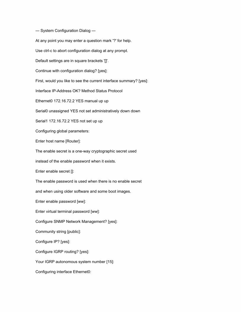
--- System Configuration Dialog ---
At any point you may enter a question mark '?' for help.
Use ctrl-c to abort configuration dialog at any prompt.
Default settings are in square brackets '[]'.
Continue with configuration dialog? [yes]:
First, would you like to see the current interface summary? [yes]:
Interface IP-Address OK? Method Status Protocol
Ethernet0 172.16.72.2 YES manual up up
Serial0 unassigned YES not set administratively down down
Serial1 172.16.72.2 YES not set up up
Configuring global parameters:
Enter host name [Router]:
The enable secret is a one-way cryptographic secret used
instead of the enable password when it exists.
Enter enable secret []:
The enable password is used when there is no enable secret
and when using older software and some boot images.
Enter enable password [ww]:
Enter virtual terminal password [ww]:
Configure SNMP Network Management? [yes]:
Community string [public]:
Configure IP? [yes]:
Configure IGRP routing? [yes]:
Your IGRP autonomous system number [15]:
Configuring interface Ethernet0:
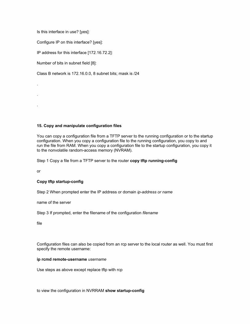
Is this interface in use? [yes]:
Configure IP on this interface? [yes]:
IP address for this interface [172.16.72.2]:
Number of bits in subnet field [8]:
Class B network is 172.16.0.0, 8 subnet bits; mask is /24
.
.
.
15. Copy and manipulate configuration files
You can copy a configuration file from a TFTP server to the running configuration or to the startup configuration. When you copy a configuration file to the running configuration, you copy to and run the file from RAM. When you copy a configuration file to the startup configuration, you copy it to the nonvolatile random-access memory (NVRAM).
Step 1 Copy a file from a TFTP server to the router copy tftp running-config
or
Copy tftp startup-config
Step 2 When prompted enter the IP address or domain ip-address or name
name of the server
Step 3 If prompted, enter the filename of the configuration filename
file
Configuration files can also be copied from an rcp server to the local router as well. You must first specify the remote username:
ip rcmd remote-username username
Use steps as above except replace tftp with rcp
to view the configuration in NVRRAM show startup-config
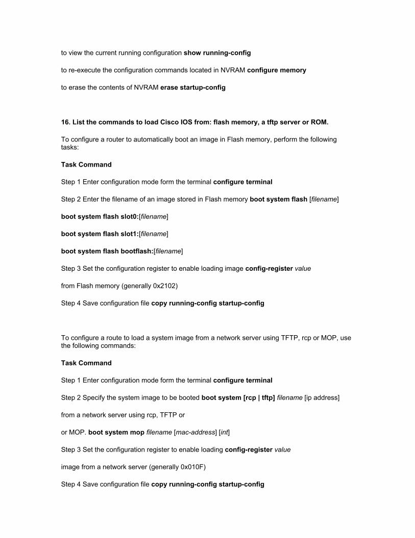
to view the current running configuration show running-config
to re-execute the configuration commands located in NVRAM configure memory
to erase the contents of NVRAM erase startup-config
16. List the commands to load Cisco IOS from: flash memory, a tftp server or ROM.
To configure a router to automatically boot an image in Flash memory, perform the following tasks:
Task Command
Step 1 Enter configuration mode form the terminal configure terminal
Step 2 Enter the filename of an image stored in Flash memory boot system flash [filename]
boot system flash slot0:[filename]
boot system flash slot1:[filename]
boot system flash bootflash:[filename]
Step 3 Set the configuration register to enable loading image config-register value
from Flash memory (generally 0x2102)
Step 4 Save configuration file copy running-config startup-config
To configure a route to load a system image from a network server using TFTP, rcp or MOP, use the following commands:
Task Command
Step 1 Enter configuration mode form the terminal configure terminal
Step 2 Specify the system image to be booted boot system [rcp | tftp] filename [ip address]
from a network server using rcp, TFTP or
or MOP. boot system mop filename [mac-address] [int]
Step 3 Set the configuration register to enable loading config-register value
image from a network server (generally 0x010F)
Step 4 Save configuration file copy running-config startup-config

To specify the use of the ROM system image as a backup to other boot instructions in the configuration file, complete the following:
Task Command
Step 1 Enter configuration mode form the terminal configure terminal
Step 2 Enter the filename of an image stored in Flash memory boot system rom
Step 3 Set the configuration register to enable loading image config-register value
from ROM (generally 0x0101)
Step 4 Save configuration file copy running-config startup-config
17. Prepare to backup, upgrade and load a backup Cisco IOS software image.
18. List the key internetworking functions of the OSI Network layer and how they are performed in a router.
19. Describe the two parts of network addressing, then identify the parts in specific protocol address examples.
A network layer address identifies an entity at the network layer of the OSI reference model. Network addresses usually exist within a hierarchical address space. They are sometimes called virtual or logical addresses. The relationship of a network address with a device is logical and unfixed. It is typically based either on physical network characteristics (the device is on a particular network segment) or on groupings that have no physical basis (the device is part of an AppleTalk zone). End systems require one network layer address for each network layer protocol they support. (This assumes that the device has only one physical network connection.) Routers and other internetworking devices require one network layer address per physical network connection for each network layer protocol supported. For example, a router with three interfaces, each running AppleTalk, TCP/IP, and OSI, must have three network layer addresses for each interface. The router therefore has nine network layer addresses.
20. List problems that each routing type encounters when dealing with topology changes and describe techniques to reduce these problems.
Distance Vector protocols, like RIP, specify a number of features designed to make their operation more stable in the face of rapid network topology changes. These include a hop-count limit, hold-downs, split horizons, and poison reverse updates.
Hop-Count Limit - RIP permits a maximum hop count of 15. Any destination greater than 15 hops away is tagged as unreachable. RIP's maximum hop count greatly restricts its use in large internetworks, but prevents a problem called count to infinity from causing endless network routing loops.
Hold-Downs - Hold-downs are used to prevent regular update messages from inappropriately reinstating a route that has gone bad. When a route goes down, neighboring routers will detect this. These routers then calculate new routes and send out routing update messages to inform their neighbors of the route change. This activity begins a wave of routing updates that filter through the network.
Triggered updates do not instantly arrive at every network device. It is therefore possible that a device that has yet to be informed of a network failure may send a regular update message (indicating that a route that has just gone down is still good) to a device that has just been notified of the network failure. In this case, the latter device now contains (and potentially advertises) incorrect routing information.
Hold-downs tell routers to hold down any changes that might affect recently removed routes for some period of time. The hold-down period is usually calculated to be just greater than the period of time necessary to update the entire network with a routing change. Hold-down prevents the count-to-infinity problem.
Split Horizons - Split horizons derive from the fact that it is never useful to send information about a route back in the direction from which it came. The split-horizon rule helps prevent two-node routing loops.
Poison Reverse Updates - Whereas split horizons should prevent routing loops between adjacent routers, poison reverse updates are intended to defeat larger routing loops. The idea is that increases in routing metrics generally indicate routing loops. Poison reverse updates are then sent to remove the route and place it in hold-down. Poison Reverse update are updates sent to other routers with an unreachable metric.
?????? Link State ???????
21. Explain the services of separate and integrated multiprotocol routing.
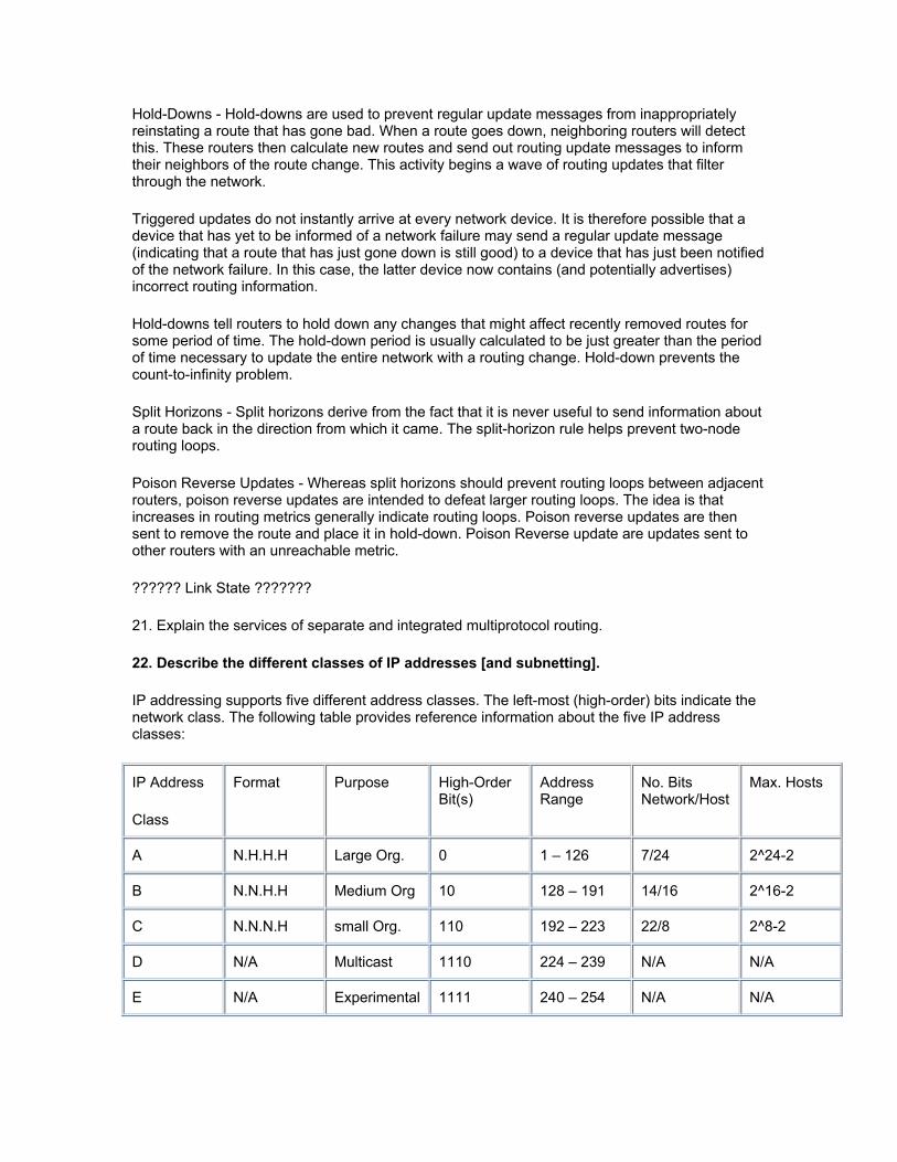
22. Describe the different classes of IP addresses [and subnetting].
IP addressing supports five different address classes. The left-most (high-order) bits indicate the network class. The following table provides reference information about the five IP address classes:
IP Address
Class
Format Purpose High-Order Bit(s)
Address Range
No. Bits Network/Host
Max. Hosts
A N.H.H.H Large Org. 0 1 – 126 7/24 2^24-2
B N.N.H.H Medium Org 10 128 – 191 14/16 2^16-2
C N.N.N.H small Org. 110 192 – 223 22/8 2^8-2
D N/A Multicast 1110 224 – 239 N/A N/A
E N/A Experimental 1111 240 – 254 N/A N/A
IP networks can be divided into smaller networks called subnetworks (or subnets). Subnetting provides extra flexibility, makes more efficient use of network address utilization, and contains broadcast traffic because a broadcast will not cross a router. Subnets are under local administration. As such, the outside world sees an organization as a single network, and has no detailed knowledge of the organization's internal structure. A given network address can be broken up into many subnetworks. For example, 172.16.1.0, 172.16.2.0, 172.16.3.0, and 172.16.4.0 are all subnets within network 171.16.0.0. (All 0s in the host portion of an address specifies the entire network.)
23. Configure IP addresses
24. Verify IP addresses
25. Prepare the initial configuration of your router and enable IP.
26. Add the RIP routing protocol to your configuration.
27. Add the IGRP routing protocol to your configuration.
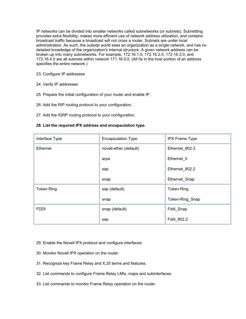
28. List the required IPX address and encapsulation type.
Interface Type Encapsulation Type IPX Frame Type
Ethernet novell-ether (default)
arpa
sap
snap
Ethernet_802.3
Ethernet_II
Ethernet_802.2
Ethernet_Snap
Token Ring sap (default)
snap
Token-Ring
Token-Ring_Snap
FDDI snap (default)
sap
Fddi_Snap
Fddi_802.2
29. Enable the Novell IPX protocol and configure interfaces.
30. Monitor Novell IPX operation on the router.
31. Recognize key Frame Relay and X.25 terms and features.
32. List commands to configure Frame Relay LMIs, maps and subinterfaces.
33. List commands to monitor Frame Relay operation on the router.
34. Identify PPP operations to encapsulate WAN data on Cisco routers.
35. Configure standard access lists to figure IP traffic.
36. Monitor and verify selected access list operations on the router.
37. State a relevant use and context for ISDN networking.
38. Identify ISDN protocols, function groups, reference points and channels.
ISDN components include terminals, terminal adapters (TAs), network-termination devices, line-termination equipment, and exchange-termination equipment. ISDN terminals come in two types. Specialized ISDN terminals are referred to as terminal equipment type 1 (TE1). Non-ISDN terminals such as DTE that predate the ISDN standards are referred to as terminal equipment type 2 (TE2). TE1s connect to the ISDN network through a four-wire, twisted-pair digital link. TE2s connect to the ISDN network through a terminal adapter. The ISDN TA can either be a stand-alone device or a board inside the TE2. If the TE2 is implemented as a standalone device, it connects to the TA via a standard physical-layer interface. Examples include EIA/TIA-232-C (formerly RS-232-C), V.24, and V.35.
Beyond the TE1 and TE2 devices, the next connection point in the ISDN network is the network termination type 1 (NT1) or network termination type 2 (NT2) device. These are network-termination devices that connect the four-wire subscriber wiring to the conventional two-wire local loop. In North America, the NT1 is a customer premises equipment (CPE) device. In most other parts of the world, the NT1 is part of the network provided by the carrier. The NT2 is a more complicated device, typically found in digital private branch exchanges (PBXs), that performs Layer 2 and 3 protocol functions and concentration services. An NT1/2 device also exists; it is a single device that combines the functions of an NT1 and an NT2.
A number of reference points are specified in ISDN. These reference points define logical interfaces between functional groupings such as TAs and NT1s. ISDN reference points include the following:
R--The reference point between non-ISDN equipment and a TA.
S--The reference point between user terminals and the NT2.
T--The reference point between NT1 and NT2 devices.
U--The reference point between NT1 devices and line-termination equipment in the carrier network.
The U reference point is relevant only in North America, where the NT1 function is not provided by the carrier network.
The ISDN Basic Rate Interface (BRI) service offers two B channels and one D channel (2B+D). BRI B-channel service operates at 64 kbps and is meant to carry user data; BRI D-channel service operates at 16 kbps and is meant to carry control and signaling information, although it can support user data transmission under certain circumstances. The D channel signaling protocol comprises Layers 1 through 3 of the OSI reference model. BRI also provides for framing control and other overhead, bringing its total bit rate to 192 kbps. The BRI physical layer
specification is International Telecommunication Union Telecommunication Standardization Sector (ITU-T) (formerly the Consultative Committee for International Telegraph and
Telephone [CCITT]) I.430.
ISDN Primary Rate Interface (PRI) service offers 23 B channels and one D channel in North America and Japan, yielding a total bit rate of 1.544 Mbps (the PRI D channel runs at 64 kbps). ISDN PRI in Europe, Australia, and other parts of the world provides 30 B plus one 64-kbps D channel and a total interface rate of 2.048 Mbps. The PRI physical-layer specification is ITU-T I.431.
ISDN physical-layer (Layer 1) frame formats differ depending on whether the frame is outbound (from terminal to network) or inbound (from network to terminal). The frames are 48 bits long, of which 36 bits represent data. Layer 2 of the ISDN signaling protocol is Link Access Procedure, D channel, also known as LAPD. LAPD is similar to High-Level Data Link Control (HDLC) and Link Access Procedure, Balanced (LAPB). As the expansion of the LAPD acronym indicates, it is used across the D channel to ensure that control and signaling information flows and is received properly. The LAPD frame format is very similar to that of HDLC and, like HDLC, LAPD uses supervisory, information, and unnumbered frames. The LAPD protocol is formally specified in ITU-T Q.920 and ITU-TQ.921.
Two Layer 3 specifications are used for ISDN signaling: ITU-T (formerly CCITT) I.450 (also known as ITU-T Q.930) and ITU-T I.451 (also known as ITU-T Q.931). Together, these protocols support user-to-user, circuit-switched, and packet-switched connections. A variety of call establishment, call termination, information, and miscellaneous messages are specified, including SETUP, CONNECT, RELEASE, USER INFORMATION, CANCEL, STATUS, and DISCONNECT. These messages are functionally similar to those provided by the X.25 protocol.
39. Describe Cisco’s implementation of ISDN BRI
40. Describe the advantages of LAN segmentation
41. Describe LAN segmentation using bridges
42. Describe LAN segmentation using routers
43. Describe LAN segmentation using switches
44. Name and describe two switching methods
45. Describe full- and half-duplex ethernet operation
46. Identify at least 3 reasons why the industry uses a layered model
47. Identify the functions of each layer of the ISO/OSI reference model
48. Define and explain the 5 conversion steps of data encapsulation
49. Identify the functions of the TCP/IP transport-layer protocols
50. Identify the functions of the TCP/IP network-layer protocols
51. Identify the functions performed by ICMP
The Internet Control Message Protocol (ICMP) is a network layer Internet protocol that provides message packets to report errors and other information relevant to IP packet processing back to the source. ICMP is documented in RFC 792. ICMP provides a number of helpful messages including the following:
Destination Unreachable - The ICMP destination unreachable message is sent by a router if it is unable to deliver a packet to the ultimate destination. The router discards the original packet. Destinations might be unreachable for these reasons:
The source host specified a nonexistent address.
The router does not have a route to the destination (less frequent).
Destination unreachable messages include the following:
Network unreachable -- This message usually implies routing or addressing failures.
Host unreachable -- This message usually implies delivery failures such as a wrong subnet mask.
Protocol unreachable -- This message usually implies that the destination does not support the upper-layer protocol specified in the packet.
Port unreachable -- This message usually implies that the Transmission Control Protocol (TCP) port (socket) is not available.
Echo Request and Reply - The ICMP echo request message is sent by any host to test node reachability across an internetwork. It is generated by the ping command. The ICMP echo reply message indicates that the node can be successfully reached.
Redirect - An ICMP redirect message is sent by the router to the source host to stimulate more efficient routing. The router still forwards the original packet to the destination. ICMP redirects allow host routing tables to remain small because knowing the address of only one router is required (even if that router does not provide the best path). Even after receiving an ICMP redirect message, some devices might continue using the less efficient route.
Time Exceeded - An ICMP time-exceeded message is sent by the router if an IP packet's Time-to-Live field (expressed in hops or seconds) reaches zero. The Time-to-Live field prevents packets from continuously circulating the internetwork if the internetwork contains a routing loop. The router discards the original packet.
Router Advertisement and Router Solicitation - The ICMP Router Discovery Protocol (IDRP) uses router advertisement and router solicitation messages to discover the addresses of routers on directly attached subnets. IDRP works as follows:
1.Each router periodically multicasts router advertisement messages from each of its interfaces.
2.Hosts discover addresses of routers on directly attached subnets by listening for these messages.
3.Hosts can use router solicitation messages to request immediate advertisements, rather than waiting for unsolicited messages.
IRDP offers several advantages over other methods of discovering addresses of neighboring routers. Primarily, it does not require hosts to recognize routing protocols, nor does it require manual configuration by an administrator. Router advertisement messages allow hosts to discover the existence of neighboring routers, but not which router is best to reach a particular destination. If a host uses a poor first-hop router to reach a particular destination, it receives a redirect message identifying a better choice.
Undeliverable ICMP messages (for whatever reason) do not generate a second ICMP message. Doing so could create an endless flood of ICMP messages.
52. Configure extended access lists to filter IP traffic
53. Configure IPX access lists and SAP filters to control basic Novell traffic
54. Monitor and verify selected access list operations on the router
55. Describe network congestion problem in ethernet networks
59. Describe the features and benefits of Fast Ethernet &
60. Describe the guidelines and distance limitations of Fast Ethernet
Fast Ethernet, or 100BaseT, is conventional Ethernet but faster, operating at 100 Mbps instead of 10 Mbps. Fast Ethernet is based on the proven CSMA/CD Media Access Control (MAC) protocol and can use existing 10BaseT cabling. Data can move from 10 Mbps to 100 Mbps without protocol translation or changes to application and networking software.
Fast Ethernet maintains CSMA/CD, the Ethernet transmission protocol. However, Fast Ethernet reduces the duration of time each bit is transmitted by a factor of 10, enabling the packet speed to increase tenfold from 10 Mbps to 100 Mbps. Data can move between Ethernet and Fast Ethernet without requiring protocol translation, because Fast Ethernet also maintains the 10BaseT error control functions as well as the frame format and length.
Fast Ethernet can run over the same variety of media as 10BaseT, including UTP, shielded twisted pair (STP), and fiber. The Fast Ethernet specification defines separate physical sublayers for each media type:
100BaseT4 for four pairs of voice- or data-grade Category 3, 4, and 5 UTP wiring
100BaseTX for two pairs of data-grade Category 5 UTP and STP wiring
100BaseFX for two strands of 62.5/125-micron multimode fiber
In many cases, organizations can upgrade to 100BaseT technology without replacing existing wiring. However, for installations with Category 3 UTP wiring in all or part of their locations, four pairs must be available to implement Fast Ethernet. The MII layer of 100BaseT couples these physical sublayers to the CSMA/CD MAC layer (see Figure 1). The MII provides a single interface that can support external transceivers for any of the 100BaseT physical sublayers. For the physical connection, the MII is implemented on Fast Ethernet devices such as routers, switches, hubs, and adapters, and on transceiver devices using a 40-pin connector
Each physical sublayer uses a signaling scheme that is appropriate to its media type. 100BaseT4 uses three pairs of wire for 100-Mbps transmission and the fourth pair for collision detection. This method lowers the 100BaseT4 signaling to 33 Mbps per pair, making it suitable for Category 3, 4, and 5 wiring. 100BaseTX uses one pair of wires for transmission (125-MHz frequency operating at 80 percent efficiency to allow for 4B5B encoding) and the other pair for collision detection and receive. 100BaseFX uses one fiber for transmission and the other fiber for collision detection and receive. The 100BaseTX and 100BaseFX physical signaling channels are based on FDDI physical layers developed and approved by the American National Standards Institute (ANSI) X3T9.5 committee.
While the 100BaseTX and 100Base T4 specifications maintain the same 100-meter limit from the wiring closet to the desktop as 10BaseT, 100BaseFX can exceed the 100-meter limit because it uses fiber instead of UTP. However, 100BaseFX is used primarily between wiring closets and campus buildings to better leverage its support for longer cables.
Just as with 10-Mbps Ethernet, different wiring types can be connected through a repeater. The 100BaseT standard defines two classes of repeaters: Class I and Class II. At most, a collision domain can include one Class I or two Class II repeaters. Fast Ethernet is implemented in a star topology, but even with repeaters, the network diameter is proportionately smaller than 10-Mbps Ethernet given Fast Ethernet's tenfold increase in packet speed. For example, using two Class II repeaters, the maximum distance using copper wire is 100 meters (m) to the Class II repeater, 5 m between Class II repeaters, and 100 m to the desktop.
Full-duplex technology delivers up to 200 Mbps bandwidth because it provides bidirectional communication -- meaning that 100 Mbps is available for transmission in each direction. Full duplex also increases the maximum distance supported for fiber cables between two Data Terminal Equipment (DTE) devices up to 2 km. Full-duplex communication is implemented by disabling the collision detection and loopback functions, which are necessary to ensure smooth communication in a shared network. Only switches can offer full duplex to directly attached
workstations or servers. Shared 100BaseT hubs must operate at half duplex to detect collisions among end stations.
The 100BaseT specification describes a negotiation process that allows devices at each end of a network link to automatically exchange information about their capabilities and perform the configuration necessary to operate together at their maximum common level. This auto-negotiation activity is performed out-of-bank using Fast Link Pulse (FLP) Burst to identify the highest physical-layer technology that can be used by both devices, such as 10BaseT, 100BaseT, 100BaseTX, or 100BaseT4. The auto-negotiation definition also provides a parallel detection function that allows half-and full-duplex 1-BaseT, half-and full-duplex
100BaseTX, and 100BaseT4 physical layers to be recognized, even if one of the connected devices does not offer auto-negotiation capabilities.
61. Distinguish between cut-through and store-and-forward switching.
Cut through switching will forward the packet as soon as the destination MAC is known. Store and forward will forward after the packet has been received and declared to be valid. Cut through is faster, but you may pass "bad" packets.
62. Describe the operation of the Spanning Tree Protocol and its benefit
Spanning-Tree Protocol is a link management protocol that provides path redundancy while preventing undesirable loops in the network. For an Ethernet network to function properly, only one active path can exist between two stations. Multiple active paths between stations cause loops in the network. If a loop exists in the network topology, the potential exists for duplication of messages. When loops occur, some switches see stations appear on both sides of the switch. This condition confuses the forwarding algorithm and allows duplicate frames to be forwarded.
To provide path redundancy, Spanning-Tree Protocol defines a tree that spans all switches in an extended network. Spanning-Tree Protocol forces certain redundant data paths into a standby (blocked) state. If one network segment in the Spanning-Tree Protocol becomes unreachable, or if Spanning-Tree Protocol costs change, the spanning-tree algorithm reconfigures the spanning-tree topology and reestablishes the link by activating the standby path.
Spanning-Tree Protocol operation is transparent to end stations, which are unaware whether they are connected to a single LAN segment or a switched LAN of multiple segments.
Election of the Root Switch
All switches in an extended LAN participating in Spanning-Tree Protocol gather information on other switches in the network through an exchange of data messages. These messages are bridge protocol data units (BPDUs). This exchange of messages results in the following:
The election of a unique root switch for the stable spanning-tree network topology.
The election of a designated switch for every switched LAN segment.

The removal of loops in the switched network by placing redundant switch ports in a backup state.
The Spanning-Tree Protocol root switch is the logical center of the spanning-tree topology in a switched network. All paths that are not needed to reach the root switch from anywhere in the switched network are placed in Spanning-Tree Protocol backup mode.
BPDUs contain information about the transmitting switch and its ports, including switch and port Media Access Control (MAC) addresses, switch priority, port priority, and port cost. The Spanning-Tree Protocol uses this information to elect the root switch and root port for the switched network, as well as the root port and designated port for each switched segment.
A BPDU exchange results in the following:
One switch is elected as the root switch.
The shortest distance to the root switch is calculated for each switch.
A designated switch is selected. This is the switch closest to the root switch through which frames will be forwarded to the root.
A port for each switch is selected. This is the port providing the best path from the switch to the root switch.
Ports included in the Spanning-Tree Protocol are selected.
If all switches are enabled with default settings, the switch with the lowest MAC address in the network becomes the root switch. By increasing the priority (lowering the numerical priority number) of the ideal switch so that it then becomes the root switch, youforce a Spanning-Tree Protocol recalculation to form a new, stable topology.
Spanning-Tree Protocol Port States
Propagation delays can occur when protocol information is passed through a switched LAN. As a result, topology changes can take place at different times and at different places in a switched network. When a switch port transitions directly from non-participation in the stable topology to the forwarding state, it can create temporary data loops. Ports must wait for new topology information to propagate through the switched LAN before starting to forward frames. They must also allow the frame lifetime to expire for frames that have been forwarded using the old topology.
Each port on a switch using Spanning-Tree Protocol exists in one of the following five states:
Blocking, Listening, Learning, Forwarding, Disabled
A port moves through these five states as follows:
From initialization to blocking
From blocking to listening or to disabled

From listening to learning or to disabled
From learning to forwarding or to disabled
From forwarding to disabled
Blocking State - A port in the blocking state does not participate in frame forwarding, as shown in Figure C-5. After initialization, a BPDU is sent to each port in the switch. A switch initially assumes it is the root until it exchanges BPDUs with other switches. This exchange establishes which switch in the network is really the root. If only one switch resides in the network, no exchange occurs, the forward delay timer expires, and the ports move to the listening state. A switch always enters the blocking state following switch initialization.
Listening State - The listening state is the first transitional state a port enters after the blocking state, when Spanning-Tree Protocol determines that the port should participate in frame forwarding. Learning is disabled in the listening state.
Learning State - A port in the learning state is preparing to participate in frame forwarding. This is the second transitional state through which a port moves in anticipation of frame forwarding. The port enters the learning state from the listening state through the operation of Spanning-Tree Protocol.
Forwarding State - A port in the forwarding state forwards frames, as shown in Figure C-5. The port enters the forwarding state from the learning state through the operation of Spanning-Tree Protocol.
Disabled State - A port in the disabled state does not participate in frame forwarding or the operation of Spanning-Tree Protocol. A port in the disabled state is virtually nonoperational.
63. Describe the benefits of Virtual LANs.
VLANs provide the following benefits:
1. Reduced Administration Costs - Moves, adds, and changes are one of the greatest expenses in managing a network. VLANs provide an effective mechanism to control these changes and reduce much of the cost of hub and router reconfiguration.
2. Controlling Broadcast Activity - Similar to routers, VLANs offer an effective mechanism for setting up firewalls in a switch fabric, protecting the network against broadcast problems that are potentially dangerous, and maintaining all the performance benefits of switching.
3. Better Network Security - You can increase security easily and inexpensively by segmenting the network into distinct broadcast groups. VLANs therefore can be used to provide security firewalls, restrict individual user access, flag any unwanted intrusion to the network, and control the size and composition of the broadcast domain.
4. Leveraging Existing LAN Hub Investments - Organizations have installed many shared hub chassis, modules, and stackable devices in the past three to five years. You can leverage this investment by using backplane hub connections. It is the connections between shared hubs and switches that provide opportunities for VLAN segmentation.
From http://www.leuthard.ch/mcse/ccnaprep.html