ccna r&s: introduction to networks - frank schneemann tools/cisco... · over its own ethernet...
TRANSCRIPT

Chapter 3: Network Protocols and Communications
CCNA R&S: Introduction to Networks
Chapter 4:
Network Access
4.0.1.1 Introduction

4.0.1.2 Activity – Managing the Medium
You and your colleague are attending a networking conference. There are many lectures and presentations held during this event, and because they overlap, each of you can only choose a limited set of sessions to attend.

4.1.1.1 Connecting to the Network

4.1.1.2 Network Interface Cards
All wireless devices must share access to the airwaves connecting to the wireless access point. This means slower network performance may occur as more wireless devices access the network simultaneously. A wired device does not need to share its access to the network with other devices. Each wired device has a separate communications channel over its own Ethernet cable. This is important when considering some applications, like online gaming, streaming video, and video conferencing, which require more dedicated bandwidth than other applications.

4.1.2.1 The Physical Layer
The OSI physical layer provides the means to transport the bits that make up a data link layer frame across the network media. This layer accepts a complete frame from the data link layer and encodes it as a series of signals that are transmitted onto the local media. The encoded bits that comprise a frame are received by either an end device or an intermediate device.

4.1.2.2 Physical Layer Media
There are three basic forms of network media. • Copper cable: The signals are
patterns of electrical pulses.• Fiber-optic cable: The signals
are patterns of light. • Wireless: The signals are
patterns of microwave transmissions

4.1.2.3 Physical Layer Standards
The protocols and operations of the upper OSI layers are performed in software designed by software engineers and computer scientists.

4.1.2.4 Lab - Identifying Network Devices and Cabling
In this lab, you will complete the following objectives: • Part 1: Identify
Network Devices • Part 2: Identify
Network Media

4.1.3.1 Physical Layer Fundamental Principles
Encoding or line encoding is a method of converting a stream of data bits into a predefined "code”. Codes are groupings of bits used to provide a predictable pattern that can be recognized by both the sender and the received.In the case of networking, encoding is a pattern of voltage or current used to represent bits; the 0s and 1s.In addition to creating codes for data, encoding methods at the physical layer may also provide codes for control purposes such as identifying the beginning and end of a frame.

4.1.3.1 Physical Layer Fundamental Principles
Signals can be transmitted in one of two ways:
• Asynchronous: Data signals are transmitted without an associated clock signal. The time spacing between data characters or blocks may be of arbitrary duration, meaning the spacing is not standardized. Therefore, frames require start and stop indicator flags.
• Synchronous: Data signals are sent along with a clock signal which occurs at evenly spaced time durations referred to as the bit time.

4.1.3.2 Bandwidth

4.1.3.3 Throughput
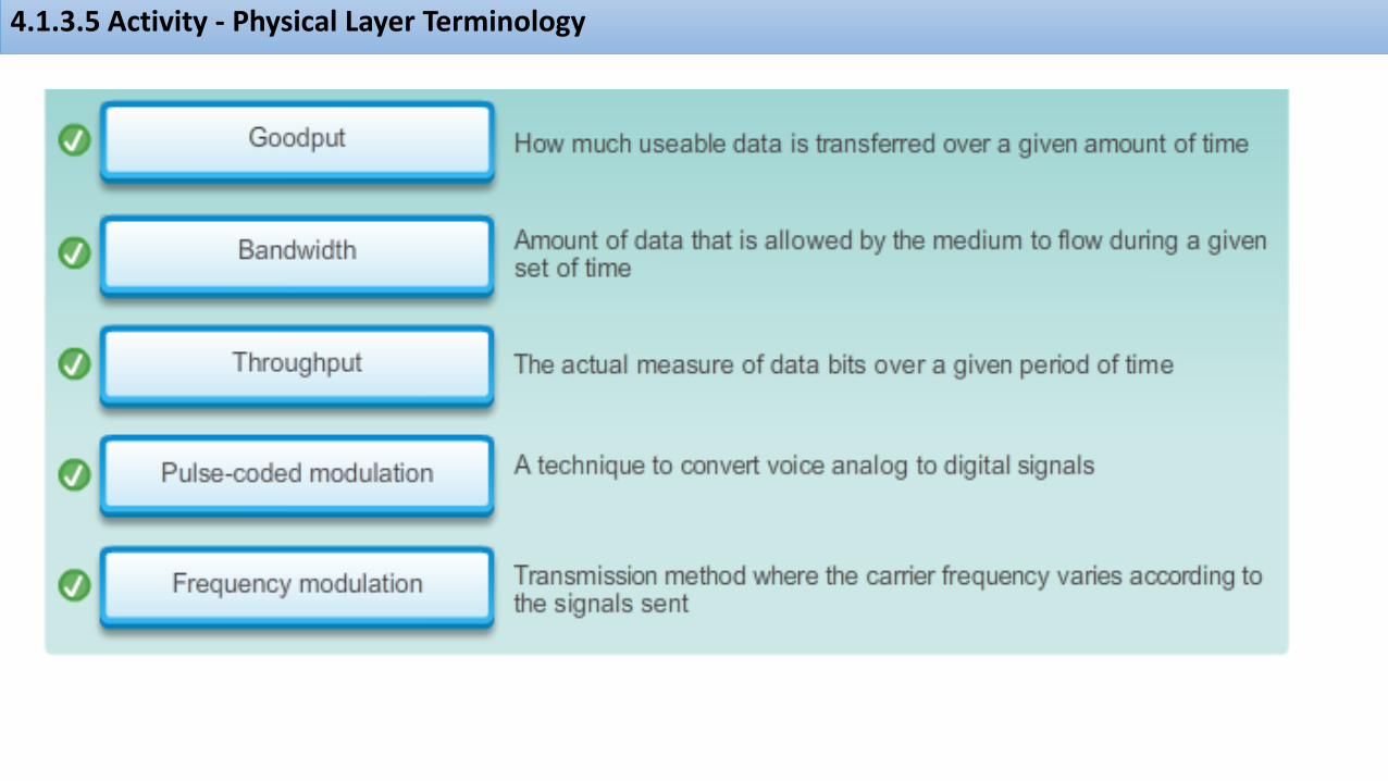
In an internetwork or network with multiple segments, throughput cannot be faster than the slowest link of the path from source to destination. Even if all or most of the segments have high bandwidth, it will only take one segment in the path with low throughput to create a bottleneck to the throughput of the entire network.
Goodput is the amount of usable data that traverses the media over a given period of time

4.1.3.4 Types of Physical Media
As an example, standards for copper media are defined for the:• Type of copper
cabling used • Bandwidth of the
communication• Type of connectors
used• Pinout and color
codes of connections to the media
• Maximum distance of the media

4.1.3.5 Activity - Physical Layer Terminology
4.1.3.5 Activity - Physical Layer Terminology

4.2.1.1 Characteristics of Copper Media
The timing and voltage values of the electrical pulses are also susceptible to interference from two sources:• Electromagnetic interference
(EMI) or radio frequency interference (RFI) - EMI and RFI signals can distort and corrupt the data signals being carried by copper media..
• Crosstalk - Crosstalk is a disturbance caused by the electric or magnetic fields of a signal on one wire to the signal in an adjacent wire.

4.2.1.2 Copper Media

4.2.1.3 Unshielded Twisted-Pair Cable

4.2.1.4 Shielded Twisted-Pair (STP) Cable

4.2.1.5 Coaxial Cable

4.2.1.6 Copper Media Safety

4.2.1.7 Activity - Copper Media Characteristics

4.2.2.1 Properties of UTP Cabling
• Cancellation: Designers now pair wires in a circuit. When two wires in an electrical circuit are placed close together, their magnetic fields are the exact opposite of each other. Therefore, the two magnetic fields cancel each other out and also cancel out any outside EMI and RFI signals.
4.2.2.2 UTP Cabling Standards
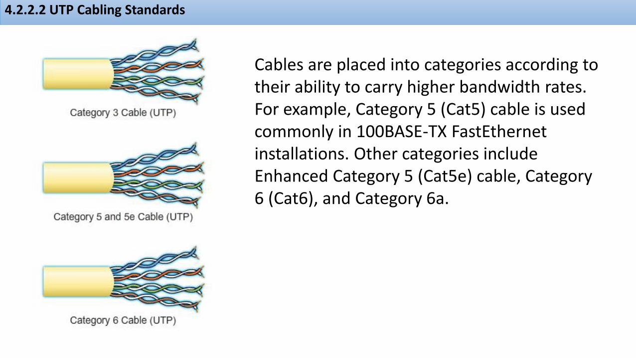
Cables are placed into categories according to their ability to carry higher bandwidth rates. For example, Category 5 (Cat5) cable is used commonly in 100BASE-TX FastEthernetinstallations. Other categories include Enhanced Category 5 (Cat5e) cable, Category 6 (Cat6), and Category 6a.

4.2.2.3 UTP Connectors
4.2.2.3 UTP Connectors

4.2.2.4 Types of UTP Cable

4.2.2.5 Testing UTP Cables
After installation, a UTP cable tester should be used to test for the following parameters:• Wire map • Cable length• Signal loss due to
attenuation• Crosstalk

4.2.2.6 Activity - Cable Pinouts

4.2.2.7 Lab - Building an Ethernet Crossover Cable

4.2.3.1 Properties of Fiber Optic Cabling
Optical fiber cable has become very popular for interconnecting infrastructure network devices. It permits the transmission of data over longer distances and at higher bandwidths (data rates) than any other networking media.
Unlike copper wires, fiber-optic cable can transmit signals with less attenuation and is completely immune to EMI and RFI.

4.2.3.2 Fiber Media Cable Design
• Core: Consists of pure glass and is the part of the fiber where light is carried. • Cladding: The glass that surrounds the core and acts as a mirror. The light pulses propagate down the core while the cladding reflects the light pulses. This keeps the light pulses contained in the fiber core in a phenomenon known as total internal reflection.

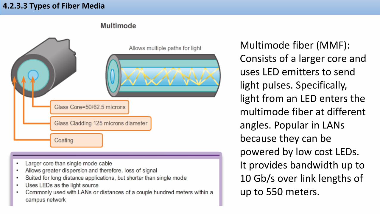
4.2.3.3 Types of Fiber Media
Single-mode fiber (SMF): Consists of a very small core and uses expensive laser technology to send a single ray of light. Popular in long-distance situations spanning hundreds of kilometers such as required in long haul telephony and cable TV applications.
4.2.3.3 Types of Fiber Media
Multimode fiber (MMF): Consists of a larger core and uses LED emitters to send light pulses. Specifically, light from an LED enters the multimode fiber at different angles. Popular in LANs because they can be powered by low cost LEDs. It provides bandwidth up to 10 Gb/s over link lengths of up to 550 meters.

4.2.3.4 Network Fiber Connectors

4.2.3.5 Testing Fiber Cables
Three common types of fiber-optic termination and splicing errors are:• Misalignment: The fiber-optic media are not precisely aligned to one another when joined.• End gap: The media does not completely touch at the splice or connection.• End finish: The media ends are not well polished or dirt is present at the termination.
A quick and easy field test can be performed by shining a bright flashlight into one end of the fiber while observing the other end of the fiber. If light is visible, then the fiber is capable of passing light. Although this does not ensure the performance of the fiber, it is a quick and inexpensive way to find a broken fiber
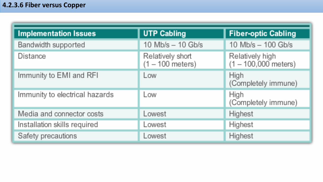
4.2.3.6 Fiber versus Copper
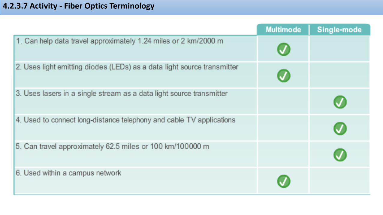
4.2.3.7 Activity - Fiber Optics Terminology

4.2.4.1 Properties of Wireless Media
Wireless does have some areas of concern including:• Coverage area: Wireless data communication technologies work well in open environments.. • Interference: Wireless is susceptible to interference and can be disrupted by such common devices as household cordless phones, some types of fluorescent lights, microwave ovens, and other wireless communications.• Security: Wireless communication coverage requires no access to a physical strand of media.

4.2.4.2 Types of Wireless Media

4.2.4.3 Wireless LAN
To use multiple Wireless Router Access points:
• Turn off DHCP and NAT except on the primary router
• Give each router a different Channel Number
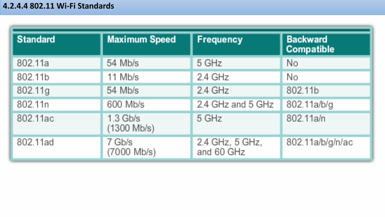
4.2.4.4 802.11 Wi-Fi Standards
4.2.4.5 Packet Tracer - Connecting a Wired and Wireless LAN

4.2.4.6 Lab - Viewing Wired and Wireless NIC Information

4.3.1.1 The Data Link Layer
As shown in the figure, the data link layer is responsible for the exchange of frames between nodes over a physical network media. It allows the upper layers to access the media and controls how data is placed and received on the media.
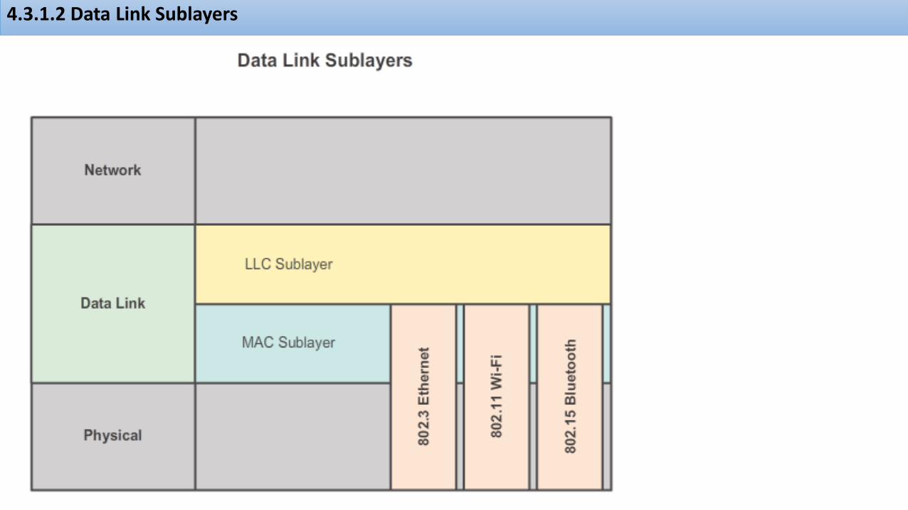
4.3.1.2 Data Link Sublayers
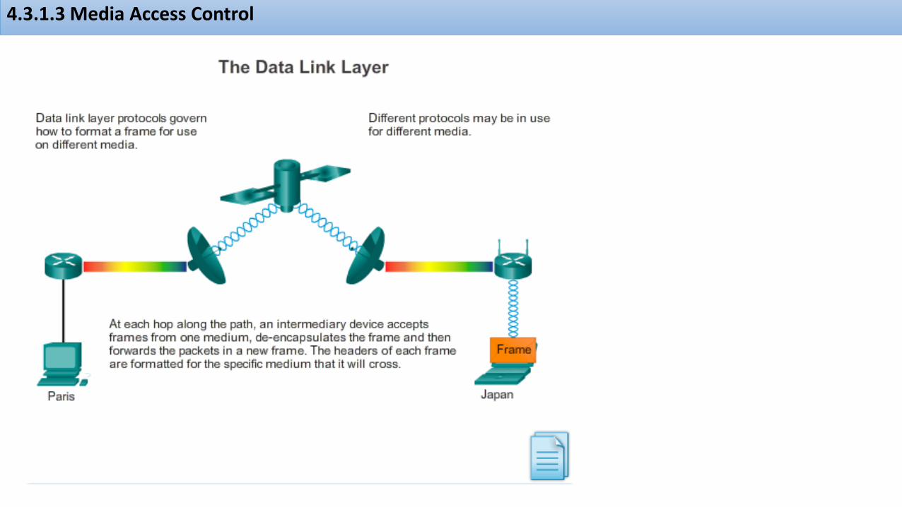
4.3.1.3 Media Access Control
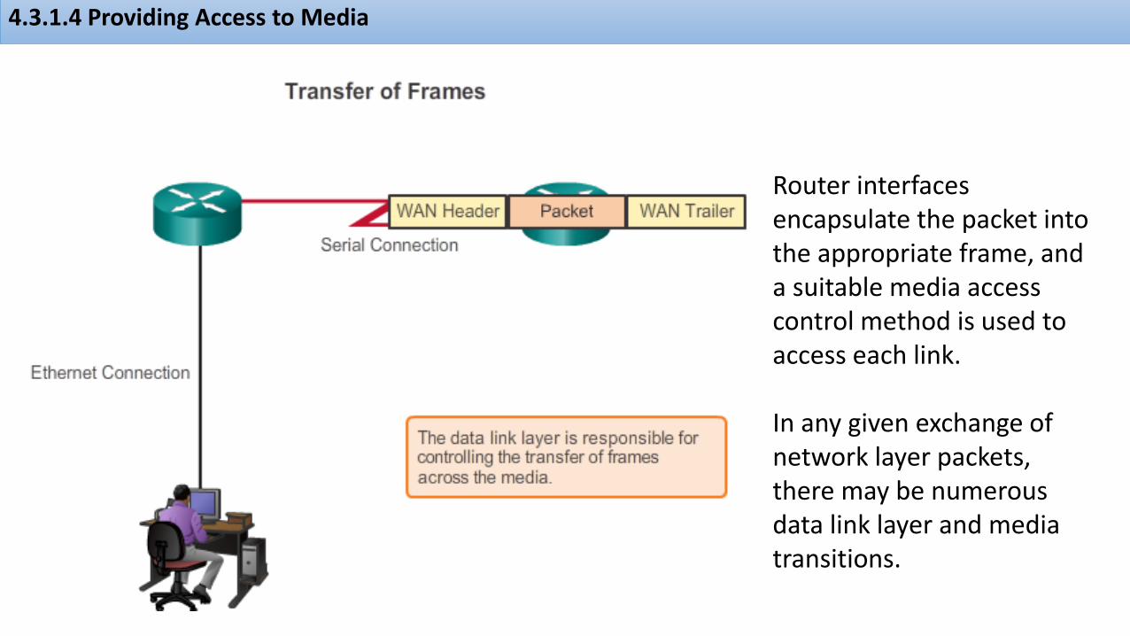
4.3.1.4 Providing Access to Media
Router interfaces encapsulate the packet into the appropriate frame, and a suitable media access control method is used to access each link.
In any given exchange of network layer packets, there may be numerous data link layer and media transitions.

4.3.2.1 Formatting Data for Transmission
Data link layer protocols require control information to enable the protocols to function. Control information typically answers:• Which nodes are in communication with each other?• When does communication between individual nodes
begin and when does it end?• Which errors occurred while the nodes communicated?• Which nodes will communicate next?

4.3.2.2 Creating a Frame
As shown in the figure, generic frame field types include: • Frame start and stop indicator flags:• Addressing: Used by the MAC sublayer to identify the source and destination nodes.• Type: Used by the LLC to identify the Layer 3 protocol.• Control: Identifies special flow control services. • Data: Contains the frame payload (i.e., packet header, segment header, and the data).• Error Detection: Included after the data to form the trailer

4.3.2.3 Activity - Generic Frame Fields

4.3.3.1 Data Link Layer Standards

4.3.3.2 Activity - Data Link Layer Standards Organizations

4.4.1.1 Controlling Access to the Media
The actual media access control method used depends on:• Topology: How the connection between the nodes appears to the data link layer. • Media sharing: How the nodes share the media. The media sharing can be point-to-point such as in WAN connections or shared such as in LAN networks

4.4.1.2 Physical and Logical Topologies

4.4.2.1 Common Physical WAN Topologies

4.4.2.2 Physical Point-to-Point Topology

4.4.2.3 Logical Point-to-Point Topology

4.4.2.4 Half and Full Duplex
. In point-to-point networks, data can flow in one of two waysHalf Duplex or Full Duplex

4.4.2.4 Half and Full Duplex

4.4.3.1 Physical LAN Topologies

4.4.3.2 Logical Topology for Shared Media

4.4.3.3 Contention-Based Access

4.4.3.4 Multi-Access Topology

4.4.3.5 Controlled Access

4.4.3.6 Ring Topology

4.4.3.7 Activity - Logical and Physical Topologies

4.4.4.1 The Frame
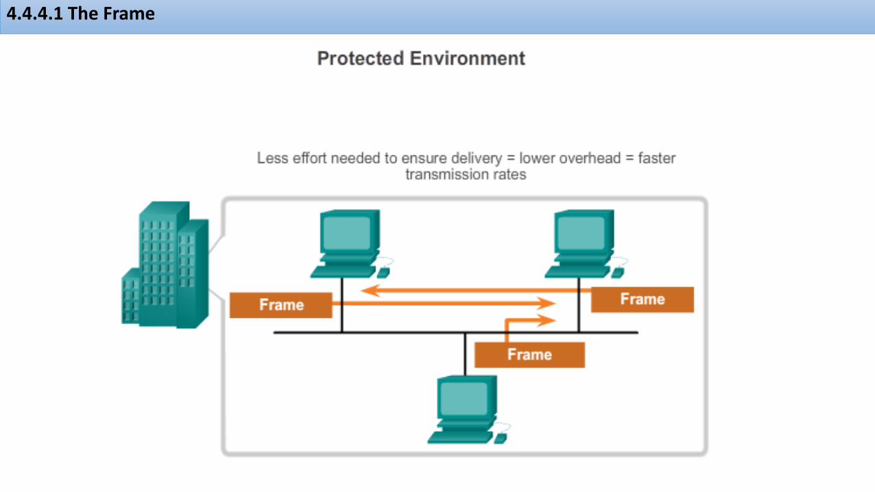
4.4.4.1 The Frame
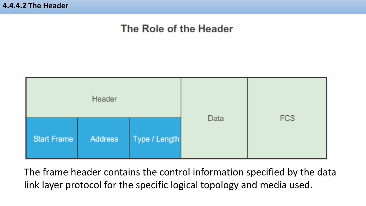
4.4.4.2 The Header
The frame header contains the control information specified by the data link layer protocol for the specific logical topology and media used.

4.4.4.3 Layer 2 Address
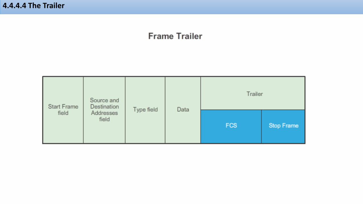
4.4.4.4 The Trailer

4.4.4.5 LAN and WAN Frames
The Layer 2 protocol used for a particular network topology is determined by the technology used to implement that topology. The technology is, in turn, determined by the size of the network - in terms of the number of hosts and the geographic scope - and the services to be provided over the network.
Common data link layer protocols include: • Ethernet • Point-to-Point Protocol (PPP) • 802.11 Wireless

4.4.4.6 Ethernet Frame
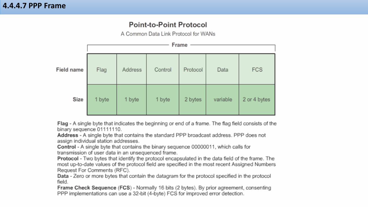
4.4.4.7 PPP Frame

4.4.4.8 802.11 Wireless Frame

4.4.4.9 Activity - Frame Fields
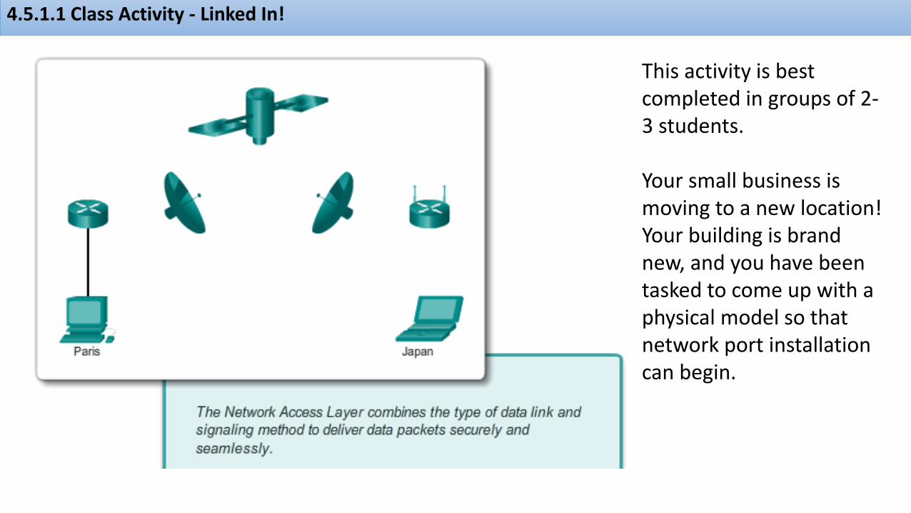
4.5.1.1 Class Activity - Linked In!
This activity is best completed in groups of 2-3 students.
Your small business is moving to a new location! Your building is brand new, and you have been tasked to come up with a physical model so that network port installation can begin.

4.5.1.2 Summary

Thanks!
Thanks for your
attention!