cb 1 series - code blue corporation--emergency blue … · this guide contains all of the cb 1...
TRANSCRIPT

800.205.7186 • www.codeblue.com
Administrator GuideInstallation, Configuration, Operation & Troubleshooting
CB 1 Series
CB 1-e CB 1-s
CB 1 Series with Public AddressCB 1-w with Solar/GSM/Wireless
Code Blue • 259 Hedcor Street • Holland, MI 49423 USA • 800.205.7186 • www.codeblue.com GU-157-Ypage 2 of 77
CB 1 SeriesAdministrator Guide
WARNINGONLY QUALIFIED PERSONNEL SHOULD INSTALL THESE UNITS. THE INSTALLATION SHOULD CONFORM TO ALL LOCAL CODES. IN SOME COUNTRIES, A CERTIFIED ELECTRI-CIAN MAY BE REQUIRED.
NOTICE TO USERS
Copyright © Code Blue Corporation. All rights reserved. This guide or software described herein, in whole or part, shall not be reproduced, translated or reduced to any machine-readable form without prior written approval from Code Blue Corporation.
CODE BLUE CORPORATION PROVIDES NO WARRANTY WITH REGARD TO THIS GUIDE, THE SOFTWARE OR OTHER INFORMATION CONTAINED HEREIN AND HEREBY EXPRESSLY DIS-CLAIMS ANY IMPLIED WARRANTIES OF MERCHANTABILITY OR FITNESS FOR ANY PARTICU-LAR PURPOSE WITH REGARD TO THIS GUIDE, THE SOFTWARE OR SUCH OTHER INFORMA-TION. IN NO EVENT SHALL CODE BLUE CORPORATION BE LIABLE FOR ANY INCIDENTAL, CONSEQUENTIAL, OR SPECIAL DAMAGES, WHETHER BASED ON TORT, CONTRACT, OR OTHERWISE, ARISING OUT OF OR IN CONNECTIONS WITH THIS GUIDE, THE SOFTWARE OR OTHER INFORMATION CONTAINED HEREIN OR THE USE THEREOF.
Code Blue Corporation reserves the right to make any modifications to this guide or the information contained herein at any time without notice. The software described herein may also be governed by the terms of a separate user license agreement.
Code Blue® is a registered trademark of Code Blue Corporation.
Code Blue • 259 Hedcor Street • Holland, MI 49423 USA • 800.205.7186 • www.codeblue.com GU-157-Ypage 3 of 77
CB 1 SeriesAdministrator Guide
Table of Contents(NOTE: Phone programming instructions can be found in the IP5000 and IA4100 Guides.) Section Page 2 Introduction.................................................................................... 5 3 Getting Started............................................................................... 7 4 Spare Parts..................................................................................... 9 5 Power Requirements.....................................................................12 6 Software Configuration.................................................................14 7 CB 1-e Low Voltage Exploded View.............................................15 8 CB 1-e High Voltage Exploded View............................................16 9 CB 1-s Low Voltage Exploded View.............................................1710 CB 1-s High Voltage Exploded View............................................1811 CB 1-s with Dual Faceplates Low Voltage Exploded View.........1912 CB 1-s with Dual Faceplates High Voltage Exploded View.......2013 CB 1-w Exploded View..................................................................2114 IP Color Camera Installation Instructions...................................2215 CB 1-e and CB 1-s Installation Instructions................................2316 CB 1 Series Tower Base Gasket Installation Instructions.........2517 CB 1-s with AED Housing Installation Instructions....................2718 CB 1-w Installation Instructions...................................................2919 Cellular Retro Instructions............................................................3220 CB 1 Series Anchor Bolt Installation Instructions......................3721 Overhead Camera Mount Installation Instructions.....................3822 Line Power Installation Instructions............................................4023 CB 1 Series Public Address Installation Instructions................4124 NightCharge® Installation Instructions........................................4325 Solar and WindAssist™ Installation Instructions.......................4526 AED Access Instructions..............................................................4927 S-1000/S-1050 Installation Instructions.......................................5028 LED Retro Area Light Installation Instructions...........................5229 PoE Installation Instructions........................................................5630 Blank Ring Installation Instructions............................................5731 CB 1 Series Deck Mount Installation Instructions......................58

Code Blue • 259 Hedcor Street • Holland, MI 49423 USA • 800.205.7186 • www.codeblue.com GU-157-Ypage 4 of 77
CB 1 SeriesAdministrator Guide
32 CB 1-e and CB 1-s 24V or Multi-Tap Power Brick Wiring (prior 2015)..5933 CB 1-e and CB 1-s 24V or Multi-Tap Power Brick Wiring (current).....6034 CB 1-e and CB 1-s Standard Wiring (with 24V Fuse Block)........................6135 CB 1-e and CB 1-s Standard Wiring (with Hammond Transformer)...............6236 CB 1-e 120V Standard Wiring Diagram (with Triad Transformer)................ 63 37 CB 1 Series NightCharge Wiring......................................................6438 CB 1 Series with Public Address Wiring.........................................6539 CB 1-w Standard Wiring....................................................................6740 GSM Wireless Wiring Diagram.........................................................6841 CB 1-s with AED, Public Address and IP Wireless.........................6942 CB 1-s with AED Wiring....................................................................7043 Multi Tap Transformer Wiring...........................................................7144 Maintenance Schedule......................................................................7245 CB 1-s with AED Access and Maintenance.....................................7446 Locating Unit Serial Numbers..........................................................7547 Warranty.............................................................................................7648 Download Information......................................................................77

Code Blue • 259 Hedcor Street • Holland, MI 49423 USA • 800.205.7186 • www.codeblue.com GU-157-Ypage 5 of 77
CB 1 SeriesAdministrator Guide
2 IntroductionThank you for choosing the CB 1 Series for your Code Blue application.
The CB 1 Series of products are the original Code Blue pedestal units that set the industry standard for rugged construction, full feature availability and high visibility. The CB 1 Series is easily recognized throughout a full 360-degree area. The user friendly lighted faceplate and the integral area light ensure rapid location in an open environment. The high output strobe is easily identifiable by security when activated.
The CB 1 Series is an excellent choice for walkways, parks, college and commercial campus areas, open landscape areas and anywhere a freestanding pedestal unit is required.
The exclusive analog InterAct and VoIP speakerphones are designed for maximum reliability, vandal resistance, auxiliary functions, mass notification control, and fault monitoring and reporting capability. (See IA4100 or IP5000 guides for more information.)
Our unmistakable craftsmanship makes our Help Points® the most rugged on the market, withstanding the punishment of natural and man-made disasters. With durable construction, our pedestal units can meet any requirement or purpose. CB 1 Series units have a rugged steel construction, shatterproof Lexan Lens, industrial engineering grade reflective graphics and weather, UV and graffiti resistant paint. They are illuminated by a high-powered, 270 lumens/92 candela LED blue beacon/strobe.
Other options include:
• IP and analog phones
• Long-life LED area light
• Low power consumption LED faceplate light
• Camera and card reader openings
• Temperature controlled automated external defibrillator (AED) housing
• 360° Public Address Speaker (PAS)
• Color IP camera
• Custom cut-out stainless steel plates
• Mounting rings
• Overhead Camera Mount
• Second opening
Code Blue • 259 Hedcor Street • Holland, MI 49423 USA • 800.205.7186 • www.codeblue.com GU-157-Ypage 6 of 77
CB 1 SeriesAdministrator Guide
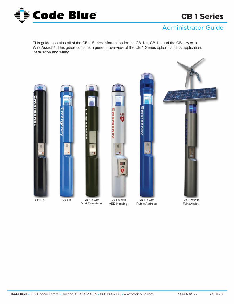
This guide contains all of the CB 1 Series information for the CB 1-e, CB 1-s and the CB 1-w with WindAssist™. This guide contains a general overview of the CB 1 Series options and its application, installation and wiring.
CB 1-s withPublic Address
CB 1-s withAED Housing
CB 1-w withWindAssist
CB 1-e CB 1-s CB 1-s withDual Faceplates
Code Blue • 259 Hedcor Street • Holland, MI 49423 USA • 800.205.7186 • www.codeblue.com GU-157-Ypage 7 of 77
CB 1 SeriesAdministrator Guide
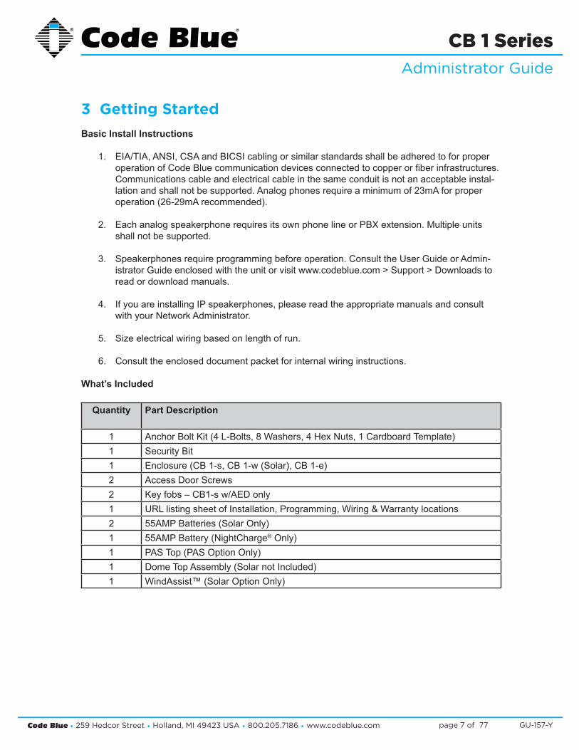
3 Getting Started Basic Install Instructions
1. EIA/TIA, ANSI, CSA and BICSI cabling or similar standards shall be adhered to for proper operation of Code Blue communication devices connected to copper or fiber infrastructures. Communications cable and electrical cable in the same conduit is not an acceptable instal- lation and shall not be supported. Analog phones require a minimum of 23mA for proper operation (26-29mA recommended).
2. Each analog speakerphone requires its own phone line or PBX extension. Multiple units shall not be supported.
3. Speakerphones require programming before operation. Consult the User Guide or Admin- istrator Guide enclosed with the unit or visit www.codeblue.com > Support > Downloads to read or download manuals.
4. If you are installing IP speakerphones, please read the appropriate manuals and consult with your Network Administrator.
5. Size electrical wiring based on length of run.
6. Consult the enclosed document packet for internal wiring instructions.
What’s Included
Quantity Part Description
1 Anchor Bolt Kit (4 L-Bolts, 8 Washers, 4 Hex Nuts, 1 Cardboard Template)1 Security Bit1 Enclosure (CB 1-s, CB 1-w (Solar), CB 1-e)2 Access Door Screws2 Key fobs – CB1-s w/AED only1 URL listing sheet of Installation, Programming, Wiring & Warranty locations2 55AMP Batteries (Solar Only)1 55AMP Battery (NightCharge® Only)1 PAS Top (PAS Option Only)1 Dome Top Assembly (Solar not Included)1 WindAssist™ (Solar Option Only)

Code Blue • 259 Hedcor Street • Holland, MI 49423 USA • 800.205.7186 • www.codeblue.com GU-157-Ypage 8 of 77
CB 1 SeriesAdministrator Guide
CB 1-e and CB 1-s Tools Required
1. Ladder to reach the top of the units
2. Drill and security bit for removing and inserting security screws on phone, dome top and access door
3. 11/8 socket set and extension for installing anchor bolts or Deck Mount Kits
4. 3/8 socket set to mount the mounting plate containing the new toroid transformer (PAS only)
5. Phillips head screwdriver and flat head screwdriver
6. 1/2-inch wrench for NightCharge® batteries, if required
CB 1-s with AED Tools Required
1. Ladder to reach the top of the units
2. Drill and security bit for removing and inserting security screws on phone, dome top and access door
3. 11/8 socket set and extension for installing anchor bolts
4. Phillips head screwdriver and flat head screwdriver
CB 1-w with WindAssist™ Tools Required
1. Ladder to reach the top of the units
2. Drill and security bit for removing and inserting security screws on phone, dome top and access door
3. 11/8 socket set and extension for installing anchor bolts
4. Phillips head screwdriver and flat head screwdriver
5. 1/2-inch wrench for solar batteries

Code Blue • 259 Hedcor Street • Holland, MI 49423 USA • 800.205.7186 • www.codeblue.com GU-157-Ypage 9 of 77
CB 1 SeriesAdministrator Guide
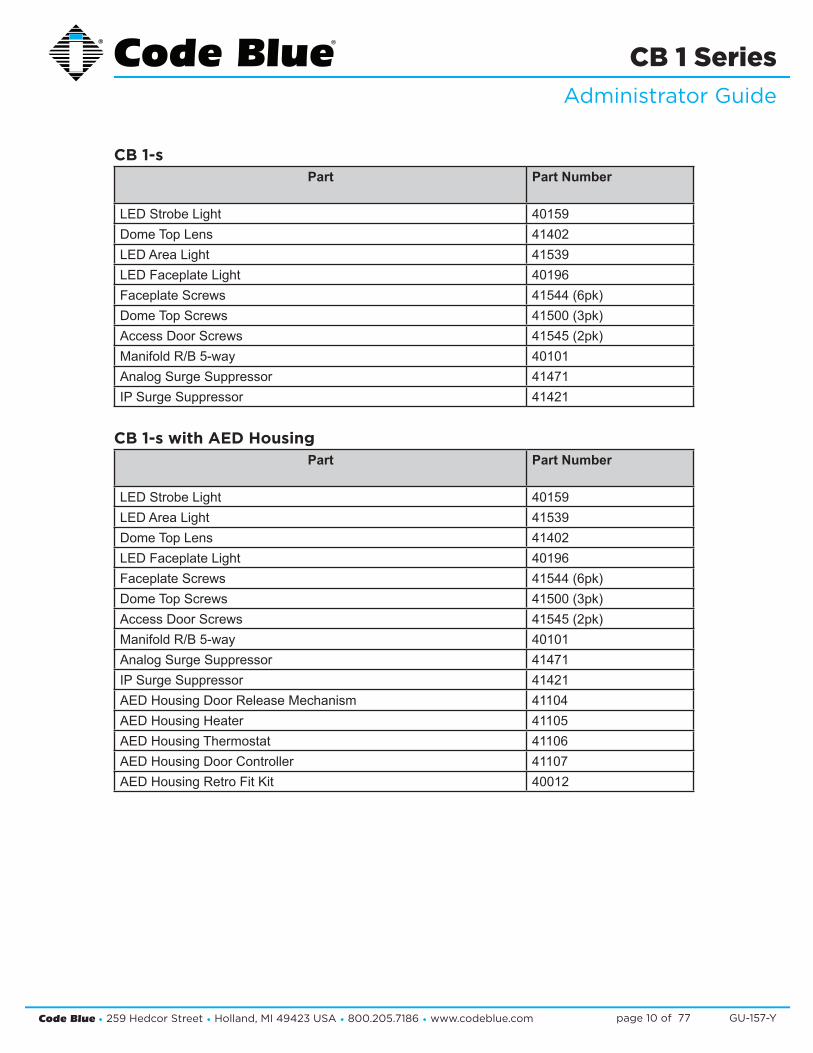
4 Spare Parts
CB 1-ePart Part Number
LED Strobe Light 40159Dome Top Lens 41402LED Faceplate Light 40196Faceplate Screws 41544 (6pk)Dome Top Screws 41500 (3pk)Access Door Screws 41545 (2pk)Manifold R/B 5-way 40101Analog Surge Suppressor 41471IP Surge Suppressor 41421
CB 1-s with Dual FaceplatesPart Part Number
LED Strobe Light 40159LED Area Light 41539Dome Top Lens 41402LED Faceplate Light 40196Faceplate Screws 41544 (6pk)Dome Top Screws 41500 (3pk)Access Door Screws 41545 (2pk)Blank Lexan Plate 40067Manifold R/B 5-way 40101Analog Surge Suppressor 41471IP Surge Suppressor 41421
Code Blue • 259 Hedcor Street • Holland, MI 49423 USA • 800.205.7186 • www.codeblue.com GU-157-Ypage 10 of 77
CB 1 SeriesAdministrator Guide
CB 1-sPart Part Number
LED Strobe Light 40159Dome Top Lens 41402LED Area Light 41539LED Faceplate Light 40196Faceplate Screws 41544 (6pk)Dome Top Screws 41500 (3pk)Access Door Screws 41545 (2pk)Manifold R/B 5-way 40101Analog Surge Suppressor 41471IP Surge Suppressor 41421
CB 1-s with AED HousingPart Part Number
LED Strobe Light 40159LED Area Light 41539Dome Top Lens 41402LED Faceplate Light 40196Faceplate Screws 41544 (6pk)Dome Top Screws 41500 (3pk)Access Door Screws 41545 (2pk)Manifold R/B 5-way 40101Analog Surge Suppressor 41471IP Surge Suppressor 41421AED Housing Door Release Mechanism 41104AED Housing Heater 41105AED Housing Thermostat 41106AED Housing Door Controller 41107AED Housing Retro Fit Kit 40012

Code Blue • 259 Hedcor Street • Holland, MI 49423 USA • 800.205.7186 • www.codeblue.com GU-157-Ypage 11 of 77
CB 1 SeriesAdministrator Guide
CB 1-wPart Part Number
LED Strobe Light 40159Dome Top Lens 41402LED Faceplate Light 40196Faceplate Screws 41544 (6pk)Dome Top Screws 41500 (3pk)Access Door Screws 41545 (2pk)Solar Batteries (2) 41537GSM 40023
CB 1-e and CB 1-s Additional OptionsPart Part Number
GSM 40022NightCharge® 45005NightCharge Batteries (1) 41537Public Address Top Need Color for Part#Overhead Camera Mount Need Color for Part#Multi Tap Transformer (powers accessories) 120V, 240V, 277V, 347V 40104120V Triad Transformer (will not power accessories) 41247Directory Plate Assembly 40056Color IP Camera with Mounting Plate 41420Blank Lexan Plate Assembly 40067Service Plate - Lexan w/graphics (This Location Being Serviced) 40208Blank Mounting Rings – 5.25 in, 5.25 in with Antenna post, 16.5 in Need Color for Part#Deck Mount Kit 40215

Code Blue • 259 Hedcor Street • Holland, MI 49423 USA • 800.205.7186 • www.codeblue.com GU-157-Ypage 12 of 77
CB 1 SeriesAdministrator Guide
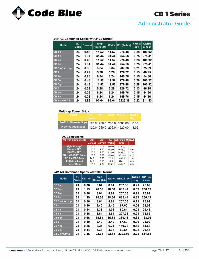
5 Power Requirements(The following power requirements include the 9 Series and also ALL OTHER Code Blue units.)
Code Blue • 259 Hedcor Street • Holland, MI 49423 USA • 800.205.7186 • www.codeblue.com GU-157-Ypage 13 of 77
CB 1 SeriesAdministrator Guide

Code Blue • 259 Hedcor Street • Holland, MI 49423 USA • 800.205.7186 • www.codeblue.com GU-157-Ypage 14 of 77
CB 1 SeriesAdministrator Guide
6 Software Configuration
Blue Alert® MNS Software
Blue Alert MNS (Mass Notification Software) fills a need in the marketplace for an incident response solution that is both comprehensive and cost-effective, while also providing an efficient way to detect and respond. The advanced mass notification system allows responders to deliver multi-layered emergency notifications via a wide range of platforms, including email, text message (SMS), emer-gency phones, public address speakers, social media, desktop alerts and more, quickly informing and directing people in emergency situations.
Blue Alert® EMS
Blue Alert EMS is an advanced software solution that handles all incoming events effectively by re-motely controlling emergency communication devices with an easy-to-use Graphical User Interface (GUI). You also will have the ability to open gates and AED access doors, turn LED beacon/strobes on or off, transfer calls to Public Address Systems to make area wide announcements and incor-porate other ancillary devices and applications while the system securely archives data for future reference.
ToolVox®
A sophisticated emergency management platform for your blue light phone network, ToolVox offers unique real-time monitoring and provisioning options for emergency phones and public address speakers, effectively acting as a hub for connecting Help Points® and other Code Blue devices. Us-ing our proprietary incident response software, Blue Alert® MNS and EMS, you can send alerts via outdoor platforms, such as blue light phones and public address speakers. It also provides connec-tions to PBX, public telephone (PSTN) and Internet (ISP) networks, in addition to third party security platforms.

Code Blue • 259 Hedcor Street • Holland, MI 49423 USA • 800.205.7186 • www.codeblue.com GU-157-Ypage 15 of 77
CB 1 SeriesAdministrator Guide
7 CB 1-e Low Voltage Exploded View
DISCLAIMER: Product design and component use subject to change without notice. Product shown reasonably represents current offering and is intended to assist in component identification. Reference the model and serial number from the unit ID tag and contact manufacturer to confirm replacement part version and availability.
BALL # PART # DESCRIPTION
1a 40260 Dome Top Kit with Strobe1b 40165 Dome Top Kit w/o Strobe1c 40166 Dome Top Kit w/o Strobe & Active Vent2 41402 Dome Top Lens3 40159 LED Blue Beacon Strobe4 41500 Button Head Security Screws (3 pk)5 CALL Standard / Custom Graphic6 41471 Analog Surge Suppressor6 41421 IP Surge Suppressor7 41548 LED Faceplate Light8 50001 Single Button IA4100 Analog Phone – PUSH FOR HELP8 50002 Double Button IA4100 Analog Phone – PUSH FOR HELP8 50003 Keypad IA4100 Analog Phone – PUSH FOR HELP8 50004 Single Button IA4100 Analog Phone – EMERGENCY8 50005 Double Button IA4100 Analog Phone – EMERGENCY8 50006 Keypad IA4100 Analog Phone – EMERGENCY8 50007 Single Button IA4100 Analog Phone – EMERGENCY/EMERGENCIA8 50008 Double Button IA4100 Analog Phone – EMERGENCY/EMERGENCIA8 50009 Keypad IA4100 Analog Phone – EMERGENCY/EMERGENCIA8 50101 Single Button IP5000 VoIP Phone – PUSH FOR HELP8 50102 Double Button IP5000 VoIP Phone – PUSH FOR HELP8 50103 Keypad IP5000 VoIP Phone – PUSH FOR HELP8 50104 Single Button IP5000 VoIP Phone – EMERGENCY8 50105 Double Button IP5000 VoIP Phone – EMERGENCY8 50106 Keypad IP5000 VoIP Phone – EMERGENCY8 50107 Single Button IP5000 VoIP Phone – EMERGENCY/EMERGENCIA8 50108 Double Button IP5000 VoIP Phone – EMERGENCY/EMERGENCIA8 50109 Keypad IP5000 VoIP Phone – EMERGENCY/EMERGENCIA9 41544 Faceplate Security Screw 10x24 (6 pk)
10 41700 24V Fuse Block11 41545 Access Door Security Screws (2 pk)12 40357 Bezel Assembly IA4100 Analog Phone – PUSH FOR HELP12 40407 Bezel Assembly IA4100 Analog Phone – EMERGENCY12 40408 Bezel Assembly IA4100 Analog Phone – EMERGENCY/EMERGENCIA12 40313 Bezel Assembly IP5000 VoIP Phone – PUSH FOR HELP12 40405 Bezel Assembly IP5000 VoIP Phone – EMERGENCY12 40406 Bezel Assembly IP5000 VoIP Phone – EMERGENCY/EMERGENCIA
2
4
1a3
5
7
8
9
12
6
10
11
1b
1c
Code Blue • 259 Hedcor Street • Holland, MI 49423 USA • 800.205.7186 • www.codeblue.com GU-157-Ypage 16 of 77
CB 1 SeriesAdministrator Guide
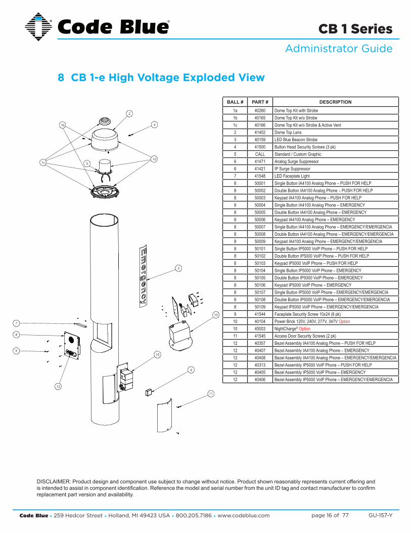
8 CB 1-e High Voltage Exploded View
DISCLAIMER: Product design and component use subject to change without notice. Product shown reasonably represents current offering and is intended to assist in component identification. Reference the model and serial number from the unit ID tag and contact manufacturer to confirm replacement part version and availability.
BALL # PART # DESCRIPTION
1a 40260 Dome Top Kit with Strobe1b 40165 Dome Top Kit w/o Strobe1c 40166 Dome Top Kit w/o Strobe & Active Vent2 41402 Dome Top Lens3 40159 LED Blue Beacon Strobe4 41500 Button Head Security Screws (3 pk)5 CALL Standard / Custom Graphic6 41471 Analog Surge Suppressor6 41421 IP Surge Suppressor7 41548 LED Faceplate Light8 50001 Single Button IA4100 Analog Phone – PUSH FOR HELP8 50002 Double Button IA4100 Analog Phone – PUSH FOR HELP8 50003 Keypad IA4100 Analog Phone – PUSH FOR HELP8 50004 Single Button IA4100 Analog Phone – EMERGENCY8 50005 Double Button IA4100 Analog Phone – EMERGENCY8 50006 Keypad IA4100 Analog Phone – EMERGENCY8 50007 Single Button IA4100 Analog Phone – EMERGENCY/EMERGENCIA8 50008 Double Button IA4100 Analog Phone – EMERGENCY/EMERGENCIA8 50009 Keypad IA4100 Analog Phone – EMERGENCY/EMERGENCIA8 50101 Single Button IP5000 VoIP Phone – PUSH FOR HELP8 50102 Double Button IP5000 VoIP Phone – PUSH FOR HELP8 50103 Keypad IP5000 VoIP Phone – PUSH FOR HELP8 50104 Single Button IP5000 VoIP Phone – EMERGENCY8 50105 Double Button IP5000 VoIP Phone – EMERGENCY8 50106 Keypad IP5000 VoIP Phone – EMERGENCY8 50107 Single Button IP5000 VoIP Phone – EMERGENCY/EMERGENCIA8 50108 Double Button IP5000 VoIP Phone – EMERGENCY/EMERGENCIA8 50109 Keypad IP5000 VoIP Phone – EMERGENCY/EMERGENCIA9 41544 Faceplate Security Screw 10x24 (6 pk)
10 40104 Power Brick 120V, 240V, 277V, 347V Option10 45003 NightCharge® Option11 41545 Access Door Security Screws (2 pk)12 40357 Bezel Assembly IA4100 Analog Phone – PUSH FOR HELP12 40407 Bezel Assembly IA4100 Analog Phone – EMERGENCY12 40408 Bezel Assembly IA4100 Analog Phone – EMERGENCY/EMERGENCIA12 40313 Bezel Assembly IP5000 VoIP Phone – PUSH FOR HELP12 40405 Bezel Assembly IP5000 VoIP Phone – EMERGENCY12 40406 Bezel Assembly IP5000 VoIP Phone – EMERGENCY/EMERGENCIA
2
4
1a3
7
8
9
12
11
5
1b
1c
10
6
10

Code Blue • 259 Hedcor Street • Holland, MI 49423 USA • 800.205.7186 • www.codeblue.com GU-157-Ypage 17 of 77
CB 1 SeriesAdministrator Guide
9 CB 1-s Low Voltage Exploded View
DISCLAIMER: Product design and component use subject to change without notice. Product shown reasonably represents current offering and is intended to assist in component identification. Reference the model and serial number from the unit ID tag and contact manufacturer to confirm replacement part version and availability.
BALL # PART # DESCRIPTION
1a 40260 Dome Top Kit with Strobe1b 40165 Dome Top Kit w/o Strobe1c 40166 Dome Top Kit w/o Strobe & Active Vent2 41402 Dome Top Lens3 40159 LED Blue Beacon Strobe4 41500 Button Head Security Screws (3 pk)5 40393 Reflective Disk6 41539 LED Area Light7 41410 HID Lens8 CALL Standard / Custom Graphic9 41471 Analog Surge Suppressor9 41421 IP Surge Suppressor
10 41548 LED Faceplate Light11 50001 Single Button IA4100 Analog Phone – PUSH FOR HELP11 50002 Double Button IA4100 Analog Phone – PUSH FOR HELP11 50003 Keypad IA4100 Analog Phone – PUSH FOR HELP11 50004 Single Button IA4100 Analog Phone – EMERGENCY11 50005 Double Button IA4100 Analog Phone – EMERGENCY11 50006 Keypad IA4100 Analog Phone – EMERGENCY11 50007 Single Button IA4100 Analog Phone – EMERGENCY/EMERGENCIA11 50008 Double Button IA4100 Analog Phone – EMERGENCY/EMERGENCIA11 50009 Keypad IA4100 Analog Phone – EMERGENCY/EMERGENCIA11 50101 Single Button IP5000 VoIP Phone – PUSH FOR HELP11 50102 Double Button IP5000 VoIP Phone – PUSH FOR HELP11 50103 Keypad IP5000 VoIP Phone – PUSH FOR HELP11 50104 Single Button IP5000 VoIP Phone – EMERGENCY11 50105 Double Button IP5000 VoIP Phone – EMERGENCY11 50106 Keypad IP5000 VoIP Phone – EMERGENCY11 50107 Single Button IP5000 VoIP Phone – EMERGENCY/EMERGENCIA11 50108 Double Button IP5000 VoIP Phone – EMERGENCY/EMERGENCIA11 50109 Keypad IP5000 VoIP Phone – EMERGENCY/EMERGENCIA12 41544 Faceplate Security Screw 10x24 (6 pk)13 41700 24V Fuse Block14 41545 Access Door Security Screws (2 pk)15 40357 Bezel Assembly IA4100 Analog Phone – PUSH FOR HELP15 40407 Bezel Assembly IA4100 Analog Phone – EMERGENCY15 40408 Bezel Assembly IA4100 Analog Phone – EMERGENCY/EMERGENCIA15 40313 Bezel Assembly IP5000 VoIP Phone – PUSH FOR HELP15 40405 Bezel Assembly IP5000 VoIP Phone – EMERGENCY15 40406 Bezel Assembly IP5000 VoIP Phone – EMERGENCY/EMERGENCIA
2
4
1a3
7
9
5
6
7
8
10
11
12
15
9
13
14
1b
1c
Code Blue • 259 Hedcor Street • Holland, MI 49423 USA • 800.205.7186 • www.codeblue.com GU-157-Ypage 18 of 77
CB 1 SeriesAdministrator Guide
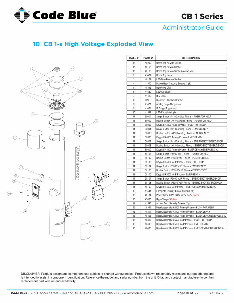
10 CB 1-s High Voltage Exploded View
DISCLAIMER: Product design and component use subject to change without notice. Product shown reasonably represents current offering and is intended to assist in component identification. Reference the model and serial number from the unit ID tag and contact manufacturer to confirm replacement part version and availability.
BALL # PART # DESCRIPTION
1a 40260 Dome Top Kit with Strobe1b 40165 Dome Top Kit w/o Strobe1c 40166 Dome Top Kit w/o Strobe & Active Vent2 41402 Dome Top Lens3 40159 LED Blue Beacon Strobe4 41500 Button Head Security Screws (3 pk)5 40393 Reflective Disk6 41539 LED Area Light7 41410 HID Lens8 CALL Standard / Custom Graphic9 41471 Analog Surge Suppressor9 41421 IP Surge Suppressor
10 41548 LED Faceplate Light11 50001 Single Button IA4100 Analog Phone – PUSH FOR HELP11 50002 Double Button IA4100 Analog Phone – PUSH FOR HELP11 50003 Keypad IA4100 Analog Phone – PUSH FOR HELP11 50004 Single Button IA4100 Analog Phone – EMERGENCY11 50005 Double Button IA4100 Analog Phone – EMERGENCY11 50006 Keypad IA4100 Analog Phone – EMERGENCY11 50007 Single Button IA4100 Analog Phone – EMERGENCY/EMERGENCIA11 50008 Double Button IA4100 Analog Phone – EMERGENCY/EMERGENCIA11 50009 Keypad IA4100 Analog Phone – EMERGENCY/EMERGENCIA11 50101 Single Button IP5000 VoIP Phone – PUSH FOR HELP11 50102 Double Button IP5000 VoIP Phone – PUSH FOR HELP11 50103 Keypad IP5000 VoIP Phone – PUSH FOR HELP11 50104 Single Button IP5000 VoIP Phone – EMERGENCY11 50105 Double Button IP5000 VoIP Phone – EMERGENCY11 50106 Keypad IP5000 VoIP Phone – EMERGENCY11 50107 Single Button IP5000 VoIP Phone – EMERGENCY/EMERGENCIA11 50108 Double Button IP5000 VoIP Phone – EMERGENCY/EMERGENCIA11 50109 Keypad IP5000 VoIP Phone – EMERGENCY/EMERGENCIA12 41544 Faceplate Security Screw 10x24 (6 pk)13 40104 Power Brick 120V, 240V, 277V, 347V Option13 45005 NightCharge® Option14 41545 Access Door Security Screws (2 pk)15 40357 Bezel Assembly IA4100 Analog Phone – PUSH FOR HELP15 40407 Bezel Assembly IA4100 Analog Phone – EMERGENCY15 40408 Bezel Assembly IA4100 Analog Phone – EMERGENCY/EMERGENCIA15 40313 Bezel Assembly IP5000 VoIP Phone – PUSH FOR HELP15 40405 Bezel Assembly IP5000 VoIP Phone – EMERGENCY15 40406 Bezel Assembly IP5000 VoIP Phone – EMERGENCY/EMERGENCIA
2
4
5
6
7
10
11
3
15
12
14
9
13
8
1c 1a
1b
13

Code Blue • 259 Hedcor Street • Holland, MI 49423 USA • 800.205.7186 • www.codeblue.com GU-157-Ypage 19 of 77
CB 1 SeriesAdministrator Guide
11 CB 1-s with Dual Faceplates Low Voltage Exploded View
DISCLAIMER: Product design and component use subject to change without notice. Product shown reasonably represents current offering and is intended to assist in component identification. Reference the model and serial number from the unit ID tag and contact manufacturer to confirm replacement part version and availability.
BALL # PART # DESCRIPTION
1a 40260 Dome Top Kit with Strobe1b 40165 Dome Top Kit w/o Strobe1c 40166 Dome Top Kit w/o Strobe & Active Vent2 41402 Dome Top Lens3 40159 LED Blue Beacon Strobe4 41500 Button Head Security Screws (3 pk)5 40393 Reflective Disk6 41539 LED Area Light7 41410 HID Lens8 CALL Standard / Custom Graphic9 41471 Analog Surge Suppressor9 41421 IP Surge Suppressor
10 41548 LED Faceplate Light11 50001 Single Button IA4100 Analog Phone – PUSH FOR HELP11 50002 Double Button IA4100 Analog Phone – PUSH FOR HELP11 50003 Keypad IA4100 Analog Phone – PUSH FOR HELP11 50004 Single Button IA4100 Analog Phone – EMERGENCY11 50005 Double Button IA4100 Analog Phone – EMERGENCY11 50006 Keypad IA4100 Analog Phone – EMERGENCY11 50007 Single Button IA4100 Analog Phone – EMERGENCY/EMERGENCIA11 50008 Double Button IA4100 Analog Phone – EMERGENCY/EMERGENCIA11 50009 Keypad IA4100 Analog Phone – EMERGENCY/EMERGENCIA11 50101 Single Button IP5000 VoIP Phone – PUSH FOR HELP11 50102 Double Button IP5000 VoIP Phone – PUSH FOR HELP11 50103 Keypad IP5000 VoIP Phone – PUSH FOR HELP11 50104 Single Button IP5000 VoIP Phone – EMERGENCY11 50105 Double Button IP5000 VoIP Phone – EMERGENCY11 50106 Keypad IP5000 VoIP Phone – EMERGENCY11 50107 Single Button IP5000 VoIP Phone – EMERGENCY/EMERGENCIA11 50108 Double Button IP5000 VoIP Phone – EMERGENCY/EMERGENCIA11 50109 Keypad IP5000 VoIP Phone – EMERGENCY/EMERGENCIA12 41544 Faceplate Security Screw 10x24 (6 pk)13 41700 24V Fuse Block14 41545 Access Door Security Screws (2 pk)15 40357 Bezel Assembly IA4100 Analog Phone – PUSH FOR HELP15 40407 Bezel Assembly IA4100 Analog Phone – EMERGENCY15 40408 Bezel Assembly IA4100 Analog Phone – EMERGENCY/EMERGENCIA15 40313 Bezel Assembly IP5000 VoIP Phone – PUSH FOR HELP15 40405 Bezel Assembly IP5000 VoIP Phone – EMERGENCY15 40406 Bezel Assembly IP5000 VoIP Phone – EMERGENCY/EMERGENCIA
2
4
5
6
7
8
10
11
3
15
12
14
9
1c 1a
1b
7
13

Code Blue • 259 Hedcor Street • Holland, MI 49423 USA • 800.205.7186 • www.codeblue.com GU-157-Ypage 20 of 77
CB 1 SeriesAdministrator Guide
12 CB 1-s with Dual Faceplates High Voltage Exploded View
DISCLAIMER: Product design and component use subject to change without notice. Product shown reasonably represents current offering and is intended to assist in component identification. Reference the model and serial number from the unit ID tag and contact manufacturer to confirm replacement part version and availability.
BALL # PART # DESCRIPTION
1a 40260 Dome Top Kit with Strobe1b 40165 Dome Top Kit w/o Strobe1c 40166 Dome Top Kit w/o Strobe & Active Vent2 41402 Dome Top Lens3 40159 LED Blue Beacon Strobe4 41500 Button Head Security Screws (3 pk)5 40393 Reflective Disk6 41539 LED Area Light7 41410 HID Lens8 CALL Standard / Custom Graphic9 41471 Analog Surge Suppressor9 41421 IP Surge Suppressor
10 41548 LED Faceplate Light11 50001 Single Button IA4100 Analog Phone – PUSH FOR HELP11 50002 Double Button IA4100 Analog Phone – PUSH FOR HELP11 50003 Keypad IA4100 Analog Phone – PUSH FOR HELP11 50004 Single Button IA4100 Analog Phone – EMERGENCY11 50005 Double Button IA4100 Analog Phone – EMERGENCY11 50006 Keypad IA4100 Analog Phone – EMERGENCY11 50007 Single Button IA4100 Analog Phone – EMERGENCY/EMERGENCIA11 50008 Double Button IA4100 Analog Phone – EMERGENCY/EMERGENCIA11 50009 Keypad IA4100 Analog Phone – EMERGENCY/EMERGENCIA11 50101 Single Button IP5000 VoIP Phone – PUSH FOR HELP11 50102 Double Button IP5000 VoIP Phone – PUSH FOR HELP11 50103 Keypad IP5000 VoIP Phone – PUSH FOR HELP11 50104 Single Button IP5000 VoIP Phone – EMERGENCY11 50105 Double Button IP5000 VoIP Phone – EMERGENCY11 50106 Keypad IP5000 VoIP Phone – EMERGENCY11 50107 Single Button IP5000 VoIP Phone – EMERGENCY/EMERGENCIA11 50108 Double Button IP5000 VoIP Phone – EMERGENCY/EMERGENCIA11 50109 Keypad IP5000 VoIP Phone – EMERGENCY/EMERGENCIA12 41544 Faceplate Security Screw 10x24 (6 pk)13 40104 Power Brick 120V, 240V, 277V, 347V Option13 45005 NightCharge® Option14 41545 Access Door Security Screws (2 pk)15 40357 Bezel Assembly IA4100 Analog Phone – PUSH FOR HELP15 40407 Bezel Assembly IA4100 Analog Phone – EMERGENCY15 40408 Bezel Assembly IA4100 Analog Phone – EMERGENCY/EMERGENCIA15 40313 Bezel Assembly IP5000 VoIP Phone – PUSH FOR HELP15 40405 Bezel Assembly IP5000 VoIP Phone – EMERGENCY15 40406 Bezel Assembly IP5000 VoIP Phone – EMERGENCY/EMERGENCIA
2
4
5
6
7
10
11
3
15
12
14
9
13
8
1c 1a
1b
13
Code Blue • 259 Hedcor Street • Holland, MI 49423 USA • 800.205.7186 • www.codeblue.com GU-157-Ypage 21 of 77
CB 1 SeriesAdministrator Guide
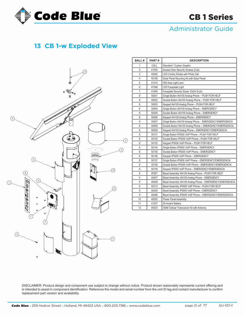
13 CB 1-w Exploded View
DISCLAIMER: Product design and component use subject to change without notice. Product shown reasonably represents current offering and is intended to assist in component identification. Reference the model and serial number from the unit ID tag and contact manufacturer to confirm replacement part version and availability.
1
2
3
4
5
6
10
11
12
12
8
7
9
2
BALL # PART # DESCRIPTION
1 CALL Standard / Custom Graphic2 41545 Access Door Security Screws (2 pk)3 40542 LED Combo Strobe with Photo Cell4 40156 Solar Panel Mounting Kit with Solar Panel5 41410 HID Area Light Lens6 41548 LED Faceplate Light7 41544 Faceplate Security Screw 10x24 (6 pk)8 50001 Single Button IA4100 Analog Phone – PUSH FOR HELP8 50002 Double Button IA4100 Analog Phone – PUSH FOR HELP8 50003 Keypad IA4100 Analog Phone – PUSH FOR HELP8 50004 Single Button IA4100 Analog Phone – EMERGENCY8 50005 Double Button IA4100 Analog Phone – EMERGENCY8 50006 Keypad IA4100 Analog Phone – EMERGENCY8 50007 Single Button IA4100 Analog Phone – EMERGENCY/EMERGENCIA8 50008 Double Button IA4100 Analog Phone – EMERGENCY/EMERGENCIA8 50009 Keypad IA4100 Analog Phone – EMERGENCY/EMERGENCIA8 50101 Single Button IP5000 VoIP Phone – PUSH FOR HELP8 50102 Double Button IP5000 VoIP Phone – PUSH FOR HELP8 50103 Keypad IP5000 VoIP Phone – PUSH FOR HELP8 50104 Single Button IP5000 VoIP Phone – EMERGENCY8 50105 Double Button IP5000 VoIP Phone – EMERGENCY8 50106 Keypad IP5000 VoIP Phone – EMERGENCY8 50107 Single Button IP5000 VoIP Phone – EMERGENCY/EMERGENCIA8 50108 Double Button IP5000 VoIP Phone – EMERGENCY/EMERGENCIA8 50109 Keypad IP5000 VoIP Phone – EMERGENCY/EMERGENCIA9 40357 Bezel Assembly IA4100 Analog Phone – PUSH FOR HELP9 40407 Bezel Assembly IA4100 Analog Phone – EMERGENCY9 40408 Bezel Assembly IA4100 Analog Phone – EMERGENCY/EMERGENCIA9 40313 Bezel Assembly IP5000 VoIP Phone – PUSH FOR HELP9 40405 Bezel Assembly IP5000 VoIP Phone – EMERGENCY9 40406 Bezel Assembly IP5000 VoIP Phone – EMERGENCY/EMERGENCIA
10 40030 Power Panel Assembly11 41537 55 AmpHr Battery12 40023 GSM Cellular Transceiver Kit with Antenna
Code Blue • 259 Hedcor Street • Holland, MI 49423 USA • 800.205.7186 • www.codeblue.com GU-157-Ypage 22 of 77
CB 1 SeriesAdministrator Guide
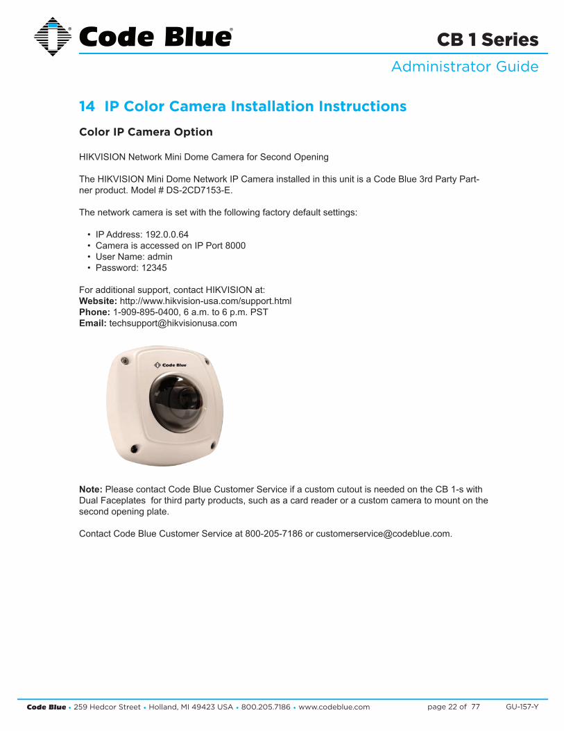
14 IP Color Camera Installation Instructions
Color IP Camera Option
HIKVISION Network Mini Dome Camera for Second Opening
The HIKVISION Mini Dome Network IP Camera installed in this unit is a Code Blue 3rd Party Part-ner product. Model # DS-2CD7153-E.
The network camera is set with the following factory default settings:
• IP Address: 192.0.0.64 • Camera is accessed on IP Port 8000 • User Name: admin • Password: 12345
For additional support, contact HIKVISION at:Website: http://www.hikvision-usa.com/support.html Phone: 1-909-895-0400, 6 a.m. to 6 p.m. PST Email: [email protected]
Note: Please contact Code Blue Customer Service if a custom cutout is needed on the CB 1-s with Dual Faceplates for third party products, such as a card reader or a custom camera to mount on the second opening plate.
Contact Code Blue Customer Service at 800-205-7186 or [email protected].
Code Blue • 259 Hedcor Street • Holland, MI 49423 USA • 800.205.7186 • www.codeblue.com GU-157-Ypage 23 of 77
CB 1 SeriesAdministrator Guide
15 CB 1-e and CB 1-s Installation Instructions 1.0 FOUNDATION (see anchor bolt installation instructions)
2.0 SET THE UNIT
2.1 Screw one set of nuts and washers onto the anchor bolts – After the foundation has set, screw one set of nuts followed by one set of washers onto the anchor bolts. Set the nuts so the lowest washer is about 2½ inches above the concrete and at an even height. To accomplish this, use a small level and check from front to back, side to side and diagonally. These nuts are NOT adjustable after the unit is in place. The bottom edge of the Code Blue unit will be ½-inch above the concrete when installed.
IMPORTANT: The leveling of the bottom nuts is crucial to the leveling of the unit. A small error in the adjustment of these will be magnified after installation.
IMPORTANT: A ½-inch minimum air gap is required between the foundation and the unit. Moisture problems may result if this condition is not complied with.
2.2 Set the Code Blue unit on the anchor bolts – Align the phone plate in the desired direction and lift the Code Blue unit over the anchor bolts. The unit may be lifted using the bracket on the inside of the unit. Note that the unit weighs approximately 330 pounds. Use appropriate lifting materials and methods to avoid possible injury and/or damage.
2.3 Secure the Code Blue unit – Access the mounting studs through the door on the side of the unit. Place the second washer, then nut and tighten the mounting nuts onto the anchor bolts. This may be more convenient if a long socket, extension and universal joint is used to tighten the hardware.
3.0 INSTALL THE AREA LIGHT (CB 1-s only)3.1 Remove packing material – Remove all packing material and ensure that the bulb is tight.3.2 Install the light fixture – Place the fixture on the bracket, just below the lens at the top of the
unit.3.3 Connect the cord – The power cord must be plugged into the plug near the bracket at the
top of the pedestal.
4.0 INSTALL THE DOME TOP ASSEMBLY
4.1 Remove the clear Lexan dome from the black metal casting. The casting complete with strobe should be brought to the top of the unit (pedestal) where the wiring will be connected (match black and red wire connectors; match yellow to yellow connectors). After the wiring is complete, set the white disc on top of the lens located inside the unit (CB 1-s only). Set the casting on top of the pedestal and fasten the casting to the bollard by reaching through the openings and tightening the three 10-24 X 1-inch stainless steel thumbscrews against the inner wall. Finally, reattach the clear Lexan dome to the black metal casting with the security screws provided. NOTE: Take care not to overdrive the security screws against the Lexan as fracturing may occur.
5.0 WIRING (refer to additional wiring instructions for the CB 1-s)5.1 Ground – The ground (green) wire should be stripped and fastened to the supplied grounding
lug.
See diagrams next page
Code Blue • 259 Hedcor Street • Holland, MI 49423 USA • 800.205.7186 • www.codeblue.com GU-157-Ypage 24 of 77
CB 1 SeriesAdministrator Guide
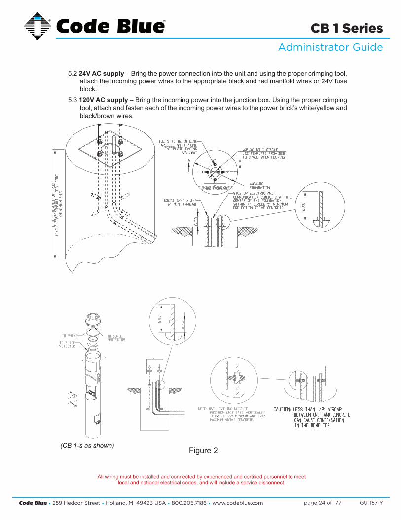
5.2 24V AC supply – Bring the power connection into the unit and using the proper crimping tool, attach the incoming power wires to the appropriate black and red manifold wires or 24V fuse block.
5.3 120V AC supply – Bring the incoming power into the junction box. Using the proper crimping tool, attach and fasten each of the incoming power wires to the power brick’s white/yellow and black/brown wires.
All wiring must be installed and connected by experienced and certified personnel to meetlocal and national electrical codes, and will include a service disconnect.
Figure 2(CB 1-s as shown)

Code Blue • 259 Hedcor Street • Holland, MI 49423 USA • 800.205.7186 • www.codeblue.com GU-157-Ypage 25 of 77
CB 1 SeriesAdministrator Guide
16 CB 1 Series Tower Base Gasket Installation Instructions 1.0 FOUNDATION (see anchor bolt installation instructions)
2.0 SET THE UNIT
2.1 Screw one set of nuts and washers onto the anchor bolts. After the foundation has set, screw one set of nuts, followed by one set of washers, onto the anchor bolts. Set the nuts so the lowest washer is about 2½ inches above the concrete at an even height.
To accomplish this, use a small level and check from front to back, side to side and diagonally. These nuts are NOT adjustable after the unit is in place. The bottom edge of the Code Blue unit will be ½-inch above the concrete when installed.
2.2 Set the Code Blue unit on the anchor bolts. Align the phone plate in the desired direction and lift the Code Blue unit over the anchor bolts. The unit may be lifted using the bracket on the inside of the unit. Note that the unit weighs approximately 200-400 pounds and that the 9 Series does not contain a bracket on the inside of the unit. Use appropriate lifting materials and methods to avoid possible injury and/or damage.
IMPORTANT: Leveling the bottom nuts is crucial to leveling the unit. A small error will be magnified after installation.
IMPORTANT: A ½-inch minimum air gap is required between the foundation and the unit to prevent moisture problems.
Code Blue • 259 Hedcor Street • Holland, MI 49423 USA • 800.205.7186 • www.codeblue.com GU-157-Ypage 26 of 77
CB 1 SeriesAdministrator Guide
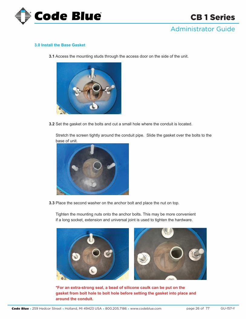
3.0 Install the Base Gasket
3.1 Access the mounting studs through the access door on the side of the unit.
3.2 Set the gasket on the bolts and cut a small hole where the conduit is located.
Stretch the screen tightly around the conduit pipe. Slide the gasket over the bolts to the base of unit.
3.3 Place the second washer on the anchor bolt and place the nut on top.
Tighten the mounting nuts onto the anchor bolts. This may be more convenient if a long socket, extension and universal joint is used to tighten the hardware.
*For an extra-strong seal, a bead of silicone caulk can be put on the gasket from bolt hole to bolt hole before setting the gasket into place and around the conduit.

Code Blue • 259 Hedcor Street • Holland, MI 49423 USA • 800.205.7186 • www.codeblue.com GU-157-Ypage 27 of 77
CB 1 SeriesAdministrator Guide
17 CB 1-s with AED Installation Instructions 1.0 FOUNDATION (see anchor bolt installation instructions)
2.0 SET THE UNIT
2.1 Screw one set of nuts and washers onto the anchor bolts – After the foundation has set, screw one set of nuts followed by one set of washers onto the anchor bolts. Set the nuts so the lowest washer is about 2½ inches above the concrete and at an even height. To accomplish this, use a small level and check from front to back, side to side and diagonally. These nuts are NOT adjustable after the unit is in place. The bottom edge of the Code Blue unit will be ½-inch above the concrete when installed.
IMPORTANT: The leveling of the bottom nuts is crucial to the leveling of the unit. A small error in the adjustment of these will be magnified after installation.
IMPORTANT: A ½-inch minimum air gap is required between the foundation and the unit. Moisture problems may result if this condition is not complied with.
2.2 Set the Code Blue unit on the anchor bolts – Align the phone plate in the desired direction and lift the Code Blue unit over the anchor bolts. The unit may be lifted using the bracket on the inside of the unit. Note that the unit weighs approximately 360 pounds. Use appropriate lifting materials and methods to avoid possible injury and/or damage.
2.3 Secure the Code Blue unit – Access the mounting studs through the door on the side of the unit. Place the second washer, then nut and tighten the mounting nuts onto the anchor bolts. This may be more convenient if a long socket, extension and universal joint is used to tighten the hardware.
3.0 INSTALL THE AREA LIGHT (CB 1-s with AED Housing only)
3.1 Remove packing material – Remove all packing material and ensure that the bulb is tight.
3.2 Install the light fixture – Place the fixture on the bracket, just below the lens at the top of the unit.
3.3 Connect the cord – The power cord must be plugged into the plug near the bracket at the top of the bollard.
4.0 INSTALL THE DOME TOP ASSEMBLY
4.1 Remove the clear Lexan dome from the black metal casting. The casting complete with strobe should be brought to the top of the unit (pedestal) where the wiring will be connected (match black and red wire connectors; match yellow to yellow connectors). After the wiring is complete, set the white disc on top of the lens located inside the unit (CB 1-s with AED Housing only). Set the casting on top of the pedestal and fasten the casting to the unit by reaching through the casting openings and tightening the three 10-24 X 1-inch stainless steel thumbscrews against the inner wall. Finally, reattach the clear Lexan dome to the black metal casting with the security screws provided.
NOTE: Take care not to overdrive the security screws against the Lexan as fracturing may occur.
See diagrams next pageAll wiring must be installed and connected by experienced and certified personnel to meet
local and national electrical codes, and will include a service disconnect.

Code Blue • 259 Hedcor Street • Holland, MI 49423 USA • 800.205.7186 • www.codeblue.com GU-157-Ypage 28 of 77
CB 1 SeriesAdministrator Guide
5.0 WIRING (refer to additional wiring instructions for the CB 1-s with AED Housing)
5.1 Ground – The ground (green) wire should be stripped and fastened to the supplied grounding lug.
5.2 24V AC supply – Using the proper crimping tool, attach a #8 fork to each of the incoming power wires and fasten them to the terminal screws labeled “Line” and “Neutral.”
5.3 120V AC supply – Using the proper crimping tool, attach a #8 fork to each of the incoming power wires and fasten tem to the terminals as labeled on the transformer. After completing the wire connections, install the supplied terminal covers.
All wiring must be installed and connected by experienced and certified personnel to meetlocal and national electrical codes, and will include a service disconnect.
Figure 1

Code Blue • 259 Hedcor Street • Holland, MI 49423 USA • 800.205.7186 • www.codeblue.com GU-157-Ypage 29 of 77
CB 1 SeriesAdministrator Guide
18 CB 1-w Installation Instructions IMPORTANT NOTICE
The following list is provided as a checklist for items required prior to installation or items that will be required on installation site:1. Batteries must be FULLY bench charged before installation.2. A local cellular dealer must provide a SIM card before unit can place calls.3. Hand/Powered tools, including torque wrench; truck or mechanical lift for the CB 1 unit.4. At least two people and ladders for attaching support collar, adjusting solar panel, etc.
1.0 FOUNDATION – (see Anchor Bolt Installation Instructions)
2.0 SET THE UNIT 2.1 Turn One Set Of Nuts And Washers Onto The Anchor Bolts – After the foundation has set,
turn one set of nuts followed by one set of washers onto the anchor bolts. Set the nuts so the lowest washer is about 2½ inches above the concrete and at an even height. To accomplish this, use a small level and check from front to back, side to side and diagonally. These nuts are NOT adjustable after the unit is in place. The bottom edge of the Code Blue unit will be ½-inch above the concrete when installed.IMPORTANT: The leveling of the bottom nuts is crucial to the leveling of the unit. A small error in the adjustment of these will be magnified after installation.IMPORTANT: A ½-inch minimum air gap is required between the foundation and the unit. Moisture problems may result if this condition is not complied with.
2.2 Set The Code Blue Unit On The Anchor Bolts – Align the phone plate in the desired direc-tion and lift the Code Blue unit over the anchor bolts. The unit may be lifted using the I-bolt provided and screwed into one of the solar threaded holes used to mount the solar panel. Note that the unit weighs approximately 400 pounds. Use appropriate lifting materials and methods to avoid possible injury and/or damage.
2.3 Secure The Code Blue Unit – Access the mounting studs through the door on the side of the unit, place the second set of washers and nuts on the studs and tighten the mounting nuts onto the anchor bolts. This may be more convenient if a long socket, extension and universal joint is used to tighten the hardware.
3.0 INSTALL THE SOLAR PANEL AND WIND GENERATOR 3.1 Adjustable universal mount
3.1.1 Attach The Aluminum Pole – Place a combination washer (rubber, then metal) on each of the three 5/8 bolts with Loctite treated threads. Attach the pole to the top of the unit. See Fig. 1 below.NOTE: Completely coat Loctite around the threads. Loctite MUST dry for 24 hours before being exposed to moisture.NOTE: Each time the bolts are removed, they must be retreated with the Loctite PST. CAUTION: Loctite PST is a skin irritant – use the enclosed rubber gloves to treat the threads.
See diagrams next page

Code Blue • 259 Hedcor Street • Holland, MI 49423 USA • 800.205.7186 • www.codeblue.com GU-157-Ypage 30 of 77
CB 1 SeriesAdministrator Guide
Dispose of gloves when completed.
3.1.2 Attach The Stainless Steel Sleeve – The sleeve must be attached to the center of the solar panel and set at the correct angle based on the unit’s latitude. Use the two 3/8 bolts and nuts and four 3/8 washers provided. See the chart below for recommended settings (Fig. 2).
3.1.3 Position The Solar Panel – Slide the sleeve and panel assembly over the collar.
NOTE: Panel must face south and be at the proper angle.
3.1.4 Once the panel is set in place, the two 3/8 set-screws should be tightened so that the panel is facing due south.
3.1.5 Wiring – Both the CB 1-w unit and the solar panel assembly are pre-wired from the fac-tory with sufficient length wires to make the opposing connection with the exception of the antenna wire. The installer may choose to use one set as a “fish-tape” to pull the wires to the necessary opposing connection or shorten both sets of wires to make a “wire-nut” connection between the two wire sets within the stainless steel collar. Attach the antenna mount to the top of the solar panel using one of the top bracket cross head screws. The antenna wire must be run through the steel collar and passed to the solar panel conduit and run out of the power distribution box. Run the antenna cable along the back side of the solar panel frame.
CAUTION: Be sure wires are not pinched during panel assembly to unit. A shorted wire or loose connection will cause unit to fail.
4.0 INSTALL THE BATTERIESNOTE: Batteries must be fully bench charged before installation.
4.1 Place The Batteries Into The Unit – Insert the battery shelf plates into the bottom access door.
SOLAR BOLLARD
GASKET
SOLAR COLLARRUBBER WASHER
METAL WASHER
HEX BOLT
APPLY LOCTITETO THREADS OF NUT
APPLY LOCTITE TOTHREADS OF BOLT
Figure 1
32º to 44º latitude 60º from horizontal23.5º to 32º latitude 45º from horizontal23.5º S to 23.5º N latitude 30º from horizontal
Figure 2
Code Blue • 259 Hedcor Street • Holland, MI 49423 USA • 800.205.7186 • www.codeblue.com GU-157-Ypage 31 of 77
CB 1 SeriesAdministrator Guide
One battery should be placed on each shelf.4.2 Connect The Wires – First connect the red wire to the positive (+) lugs on the batteries, then
connect the black wire to the negative (-) lugs. WARNING: Reversing the battery wires (reversed polarity) will cause damage to the charge
controller.

Code Blue • 259 Hedcor Street • Holland, MI 49423 USA • 800.205.7186 • www.codeblue.com GU-157-Ypage 32 of 77
CB 1 SeriesAdministrator Guide
19 Cellular Retro InstructionsTELULAR SX-5E & CALLFINDER CX100FX2 GSM-4 TO GSM-5
Installation Instructions
Retrofit Instructions Telular & CallFinder
We strongly advise reading these instruction before any work is started. In addition, the age of these units is possible the actual wiring may have changed by others, therefore the wiring guides provided are originals and here for your reference.
Some early 2002 designs: a total rebuild is more effective and easier to accomplish. Contact customer service a rebuild kit.
Telular GSM Removal Instructions Specifically
Current Installations: If you still have a Telular cellular F.C.T. (Fixed Cellular Termi-nal), inside your CB1 NightCharge™ or CB1w (Solar), CB 4-u NightCharge™ or CB 4-u Solar enclosure, it is a hardwired internal harness. The wiring in the enclosure is bundled; therefore removing two wires from the bundled group is very time consum-ing. You may choose to reuse existing wiring, cutting and splicing the power wires is acceptable, if doing so, use self-sealing splices.
Consideration: abandoning the original power wires will require you to identify the harness and power panel in order to properly attach the new GSM-5 power wires. Review the list below for the most common configurations. Hint: Cellular power terminate on the same buss as the Battery.
Models involved in this Retro – Visual Refer document AttachedCB1 CB 4-uNightCharge™ 2002, 2005, 20t10 NightCharge™ 2002, 2005, 2010
W Solar 2005, 2008, 2010 - 2013 Solar 2005, 2008, 2010 - 2013
Code Blue • 259 Hedcor Street • Holland, MI 49423 USA • 800.205.7186 • www.codeblue.com GU-157-Ypage 33 of 77
CB 1 SeriesAdministrator Guide
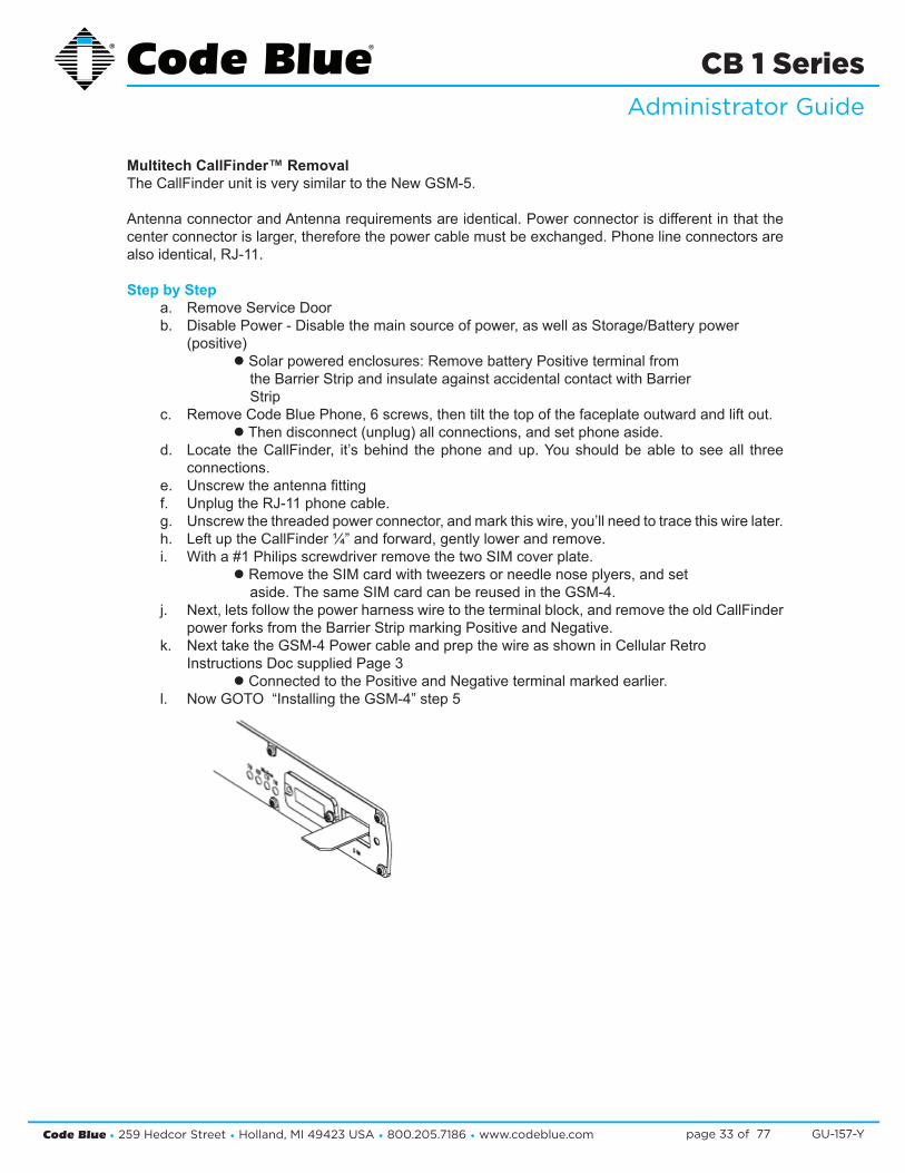
Multitech CallFinder™ RemovalThe CallFinder unit is very similar to the New GSM-5.
Antenna connector and Antenna requirements are identical. Power connector is different in that the center connector is larger, therefore the power cable must be exchanged. Phone line connectors are also identical, RJ-11.
Step by Stepa. Remove Service Door b. Disable Power - Disable the main source of power, as well as Storage/Battery power
(positive) l Solar powered enclosures: Remove battery Positive terminal from the Barrier Strip and insulate against accidental contact with Barrier Strip
c. Remove Code Blue Phone, 6 screws, then tilt the top of the faceplate outward and lift out. l Then disconnect (unplug) all connections, and set phone aside.
d. Locate the CallFinder, it’s behind the phone and up. You should be able to see all three connections.
e. Unscrew the antenna fittingf. Unplug the RJ-11 phone cable. g. Unscrew the threaded power connector, and mark this wire, you’ll need to trace this wire later. h. Left up the CallFinder ¼” and forward, gently lower and remove. i. With a #1 Philips screwdriver remove the two SIM cover plate.
l Remove the SIM card with tweezers or needle nose plyers, and set aside. The same SIM card can be reused in the GSM-4.
j. Next, lets follow the power harness wire to the terminal block, and remove the old CallFinder power forks from the Barrier Strip marking Positive and Negative.
k. Next take the GSM-4 Power cable and prep the wire as shown in Cellular Retro Instructions Doc supplied Page 3 l Connected to the Positive and Negative terminal marked earlier.
l. Now GOTO “Installing the GSM-4” step 5
Code Blue • 259 Hedcor Street • Holland, MI 49423 USA • 800.205.7186 • www.codeblue.com GU-157-Ypage 34 of 77
CB 1 SeriesAdministrator Guide
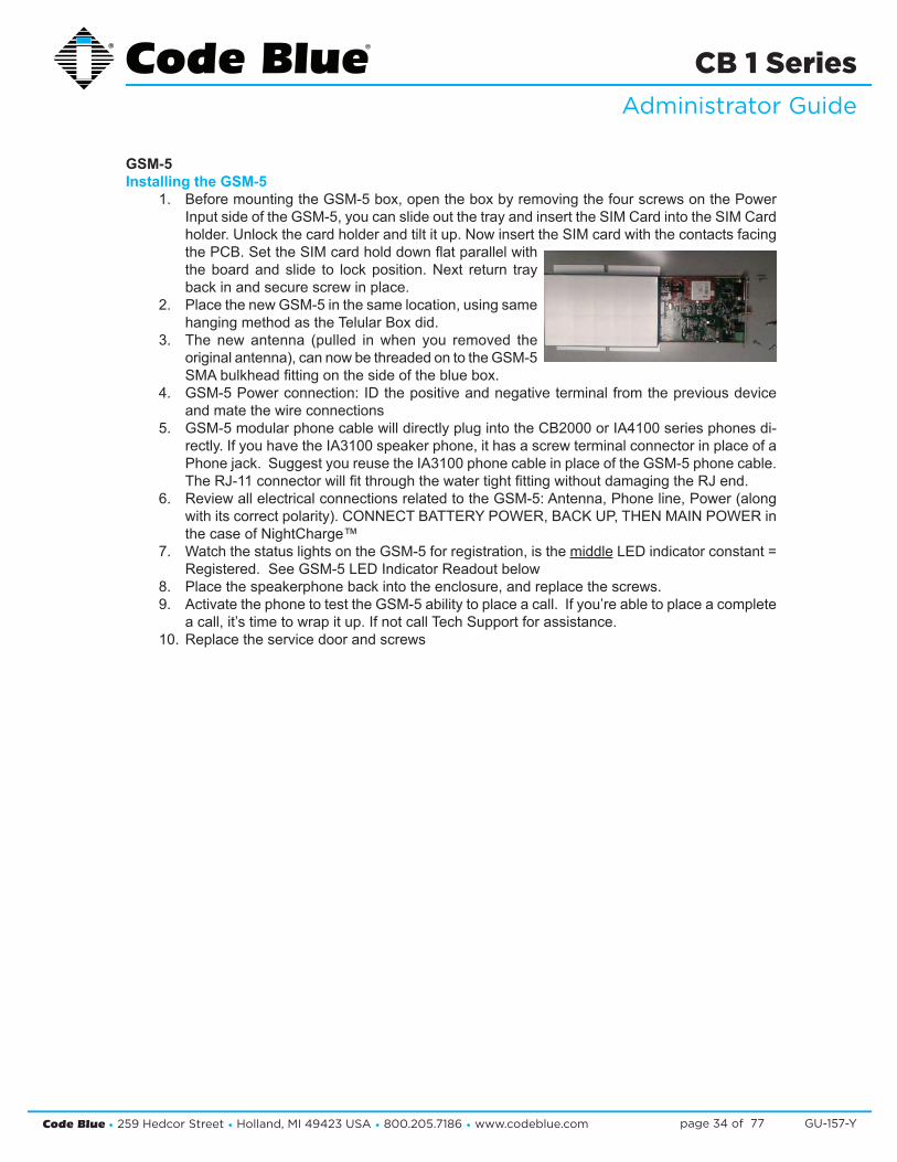
GSM-5Installing the GSM-5
1. Before mounting the GSM-5 box, open the box by removing the four screws on the Power Input side of the GSM-5, you can slide out the tray and insert the SIM Card into the SIM Card holder. Unlock the card holder and tilt it up. Now insert the SIM card with the contacts facing the PCB. Set the SIM card hold down flat parallel with the board and slide to lock position. Next return tray back in and secure screw in place.
2. Place the new GSM-5 in the same location, using same hanging method as the Telular Box did.
3. The new antenna (pulled in when you removed the original antenna), can now be threaded on to the GSM-5 SMA bulkhead fitting on the side of the blue box.
4. GSM-5 Power connection: ID the positive and negative terminal from the previous device and mate the wire connections
5. GSM-5 modular phone cable will directly plug into the CB2000 or IA4100 series phones di-rectly. If you have the IA3100 speaker phone, it has a screw terminal connector in place of a Phone jack. Suggest you reuse the IA3100 phone cable in place of the GSM-5 phone cable. The RJ-11 connector will fit through the water tight fitting without damaging the RJ end.
6. Review all electrical connections related to the GSM-5: Antenna, Phone line, Power (along with its correct polarity). CONNECT BATTERY POWER, BACK UP, THEN MAIN POWER in the case of NightCharge™
7. Watch the status lights on the GSM-5 for registration, is the middle LED indicator constant = Registered. See GSM-5 LED Indicator Readout below
8. Place the speakerphone back into the enclosure, and replace the screws.9. Activate the phone to test the GSM-5 ability to place a call. If you’re able to place a complete
a call, it’s time to wrap it up. If not call Tech Support for assistance. 10. Replace the service door and screws
Code Blue • 259 Hedcor Street • Holland, MI 49423 USA • 800.205.7186 • www.codeblue.com GU-157-Ypage 35 of 77
CB 1 SeriesAdministrator Guide
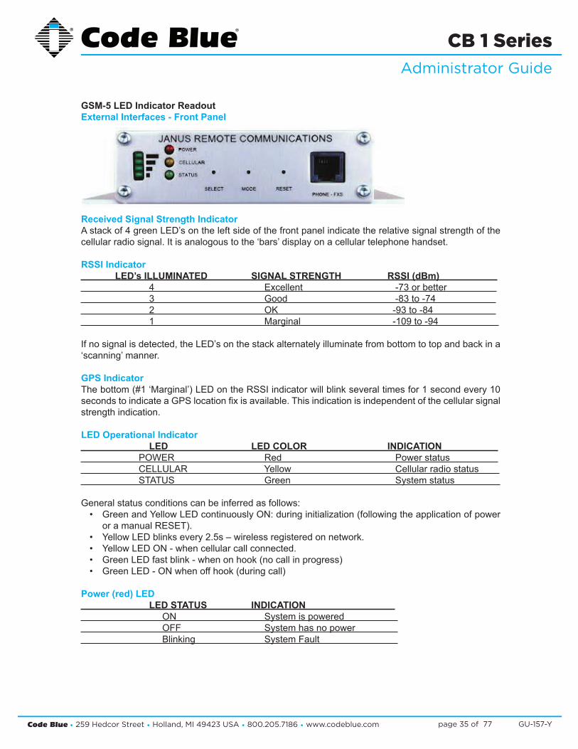
GSM-5 LED Indicator ReadoutExternal Interfaces - Front Panel
Received Signal Strength IndicatorA stack of 4 green LED’s on the left side of the front panel indicate the relative signal strength of the cellular radio signal. It is analogous to the ‘bars’ display on a cellular telephone handset.
RSSI Indicator LED’s ILLUMINATED SIGNAL STRENGTH RSSI (dBm) 4 Excellent -73 or better 3 Good -83 to -74 2 OK -93 to -84 1 Marginal -109 to -94
If no signal is detected, the LED’s on the stack alternately illuminate from bottom to top and back in a ‘scanning’ manner.
GPS IndicatorThe bottom (#1 ‘Marginal’) LED on the RSSI indicator will blink several times for 1 second every 10 seconds to indicate a GPS location fix is available. This indication is independent of the cellular signal strength indication.
LED Operational Indicator LED LED COLOR INDICATION POWER Red Power status CELLULAR Yellow Cellular radio status STATUS Green System status
General status conditions can be inferred as follows: • Green and Yellow LED continuously ON: during initialization (following the application of power
or a manual RESET). • Yellow LED blinks every 2.5s – wireless registered on network. • Yellow LED ON - when cellular call connected. • Green LED fast blink - when on hook (no call in progress) • Green LED - ON when off hook (during call)
Power (red) LED LED STATUS INDICATION ON System is powered OFF System has no power Blinking System Fault

Code Blue • 259 Hedcor Street • Holland, MI 49423 USA • 800.205.7186 • www.codeblue.com GU-157-Ypage 36 of 77
CB 1 SeriesAdministrator Guide
Cellular (yellow) LED LED STATUS CELLULAR RADIO OFF Off ON * Not registered - or - Call active Blinking 1sec on + 2 sec off Registered in idle * When the CELLULAR LED stays on (not registered) for more than a few minutes after powering the POTSwap, it is usually an indication of a poor antenna connection or a problem with the activation on the cellular network. Check that the SIM card is properly installed and that it has valid activation with a cellular carrier.
Status (green) LED LED STATUS INDICATION ON Phone line 9RJ11) is OFF-HOOK (also during initialization) Blinking fast (12.5 Hz) Phone line (RJ11) is ON-HOOK Blinking slow (1 Hz) Initializing
Code Blue • 259 Hedcor Street • Holland, MI 49423 USA • 800.205.7186 • www.codeblue.com GU-157-Ypage 37 of 77
CB 1 SeriesAdministrator Guide
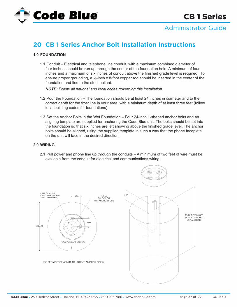
20 CB 1 Series Anchor Bolt Installation Instructions 1.0 FOUNDATION
1.1 Conduit – Electrical and telephone line conduit, with a maximum combined diameter of four inches, should be run up through the center of the foundation hole. A minimum of four inches and a maximum of six inches of conduit above the finished grade level is required. To ensure proper grounding, a ½-inch x 8-foot copper rod should be inserted in the center of the foundation and tied to the steel bollard. NOTE: Follow all national and local codes governing this installation.
1.2 Pour the Foundation – The foundation should be at least 24 inches in diameter and to the correct depth for the frost line in your area, with a minimum depth of at least three feet (follow local building codes for foundations).
1.3 Set the Anchor Bolts in the Wet Foundation – Four 24-inch L-shaped anchor bolts and an aligning template are supplied for anchoring the Code Blue unit. The bolts should be set into the foundation so that six inches are left showing above the finished grade level. The anchor bolts should be aligned, using the supplied template in such a way that the phone faceplate on the unit will face in the desired direction.
2.0 WIRING
2.1 Pull power and phone line up through the conduits – A minimum of two feet of wire must be available from the conduit for electrical and communications wiring.
TO BE DETERMINEDBY FROST LINE AND
LOCAL CODES
6.00
4.00
4.00
24.00
8.00BOLT CIRCLE
FOR ANCHOR BOLTS
KEEP CONDUITCONTAINED WITHIN4.00" DIAMETER
PHONE FACEPLATE DIRECTION
USE PROVIDED TEMPLATE TO LOCATE ANCHOR BOLTS
Code Blue • 259 Hedcor Street • Holland, MI 49423 USA • 800.205.7186 • www.codeblue.com GU-157-Ypage 38 of 77
CB 1 SeriesAdministrator Guide
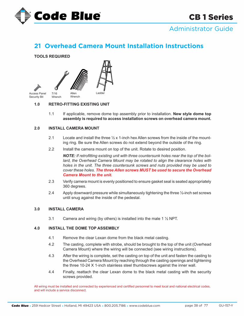
21 Overhead Camera Mount Installation Instructions TOOLS REQUIRED
1.0 RETRO-FITTING EXISTING UNIT
1.1 If applicable, remove dome top assembly prior to installation. New style dome top assembly is required to access installation screws on overhead camera mount.
2.0 INSTALL CAMERA MOUNT
2.1 Locate and install the three ½ x 1-inch hex Allen screws from the inside of the mount-ing ring. Be sure the Allen screws do not extend beyond the outside of the ring.
2.2 Install the camera mount on top of the unit. Rotate to desired position. NOTE: If retrofitting existing unit with three countersunk holes near the top of the bol-lard, the Overhead Camera Mount may be rotated to align the clearance holes with holes in the unit. The three countersunk screws and nuts provided may be used to cover these holes. The three Allen screws MUST be used to secure the Overhead Camera Mount to the unit.
2.3 Verify camera mount is evenly positioned to ensure gasket seal is seated appropriately 360 degrees.
2.4 Apply downward pressure while simultaneously tightening the three ½-inch set screws until snug against the inside of the pedestal.
3.0 INSTALL CAMERA
3.1 Camera and wiring (by others) is installed into the male 1 ½ NPT.
4.0 INSTALL THE DOME TOP ASSEMBLY
4.1 Remove the clear Lexan dome from the black metal casting. 4.2 The casting, complete with strobe, should be brought to the top of the unit (Overhead
Camera Mount) where the wiring will be connected (see wiring instructions).4.3 After the wiring is complete, set the casting on top of the unit and fasten the casting to
the Overhead Camera Mount by reaching through the casting openings and tightening the three 10-24 X 1-inch stainless steel thumbscrews against the inner wall.
4.4 Finally, reattach the clear Lexan dome to the black metal casting with the security screws provided.
All wiring must be installed and connected by experienced and certified personnel to meet local and national electrical codes, and will include a service disconnect.
7/16Wrench
LadderAccess Panel Security Bit
Allen Wrench

Code Blue • 259 Hedcor Street • Holland, MI 49423 USA • 800.205.7186 • www.codeblue.com GU-157-Ypage 39 of 77
CB 1 SeriesAdministrator Guide
Lexan Dome Top
LED Area Light
Dome Metal Casting
Overhead Camera Mount
Gasket Seal
CB Unit6
5
4
3
2
1
Code Blue®
Overhead Camera Mount Installation Instructions IN-13208-B
All wiring must be installed and connected by experienced and certified personnel to meet local and national electrical codes, and will include a service disconnect.
Lexan Dome Top
LED Area Light
Dome Metal Casting
Overhead Camera Mount
Gasket Seal
CB Bollard6
5
4
3
2
1
Overhead Camera MountInstallation Instructions
Page 2 of 2

Code Blue • 259 Hedcor Street • Holland, MI 49423 USA • 800.205.7186 • www.codeblue.com GU-157-Ypage 40 of 77
CB 1 SeriesAdministrator Guide
22 Line Power Installation Instructions (Excludes NightCharge® and Solar Options)
IMPORTANT: All wiring shall comply with national and local codes governing this installation. It is the responsibility of the installer to ensure these conditions are complied with.
1.0 SUPPLY WIRING
1.1 Pulling the power wires – Wire should be a minimum of 14 AWG and be pulled into the unit, leaving a minimum of two feet of wire from the opening of the conduit.
1.2 Pulling the communications wire (if needed) – Communications wire must be shielded phone line. The phone line must be pulled into the unit using a separate conduit from the power, and be run so as to extend a minimum of two feet out of the phone opening.
2.0 CONNECT THE POWER WIRES
2.1 Make the connections – Locate the grounding lug and connect the ground wire.
2.2 Using 115V AC supply – Connect the colored (hot) wire to the black wire, and connect the white or gray (neutral) wire to the white wire.
2.3 Higher voltage supply – If the unit was ordered for a higher voltage, a pre-wired power brick will be located on the top of the electrical panel with a 24 volt secondary to supply the low voltage manifold and power brick to supply the area light. Connect the colored (hot) wire and the white or gray (neutral) wire to the white wire in the junction box.
3.0 CONNECT THE PHONE LINE (if required) – See phone Installation Instructions.
4.0 APPLY POWER – The unit should become operational immediately after the power is ener-gized.

Code Blue • 259 Hedcor Street • Holland, MI 49423 USA • 800.205.7186 • www.codeblue.com GU-157-Ypage 41 of 77
CB 1 SeriesAdministrator Guide
23 CB 1 Series Public Address Installation Instructions 1.0 FOUNDATION (see Anchor Bolt Installation Instructions)
2.0 SET THE UNIT
2.1 Screw one set of nuts and washers onto the anchor bolts – After the foundation has set, screw one set of nuts followed by one set of washers onto the anchor bolts. Set the nuts so the lowest washer is about 2½ inches above the concrete and at an even height. To accom-plish this, use a small level and check from front to back, side to side and diagonally. These nuts are NOT adjustable after the unit is in place. The bottom edge of the Code Blue unit will be ½-inch above the concrete when installed.
MPORTANT: The leveling of the bottom nuts is crucial to the leveling of the unit. A small er-ror in the adjustment of these will be magnified after installation. MPORTANT: A ½-inch minimum air gap is required between the foundation and the unit. Moisture problems may result if this condition is not complied with.
2.2 Set the Code Blue unit on the anchor bolts – Align the phone plate in the desired direc-tion and lift the Code Blue unit over the anchor bolts. The unit may be lifted using the bracket on the inside of the unit.
Note that the unit weighs approximately 390 pounds. Use appropriate lifting materials and methods to avoid possible injury and/or damage.
2.3 Secure the Code Blue unit – Access the mounting studs through the door on the side of the unit. Place the second washer then nut and then tighten the mounting nuts onto the anchor bolts. This may be more convenient if a long socket, extension and universal joint is used to tighten the hardware.
3.0 INSTALL THE DOME TOP ASSEMBLY
3.1 Remove the clear Lexan dome from the black metal casting. The casting, complete with strobe, should be brought to the top of the unit where the wiring will be connected (match black and red wire connectors; match yellow to yellow connectors).
3.2 After the wiring is complete, set the white disc on top of the lens located inside the unit (CB 1-d/1-s with Public Address only).
3.3 Set the casting on top of the unit and fasten the casting by reaching through the casting openings and tightening the three 10-24 X 1-inch stainless steel thumbscrews against the inner wall.
3.4 Finally, reattach the clear Lexan dome to the black metal casting with the security screws provided. NOTE: Take care not to overdrive the security screws against the Lexan as fracturing may occur.
4.0 WIRING (refer to PAS WIRING DIAGRAM for additional details)
4.1 Ground – The ground (green) wire should be stripped and fastened to the supplied ground-ing lug.
4.2 24V AC supply – Using the proper crimping tool, attach a #8 fork to each of the incoming power wires and fasten them to the terminal screws labeled “Line” and “Neutral.”
See diagrams next page
Code Blue • 259 Hedcor Street • Holland, MI 49423 USA • 800.205.7186 • www.codeblue.com GU-157-Ypage 42 of 77
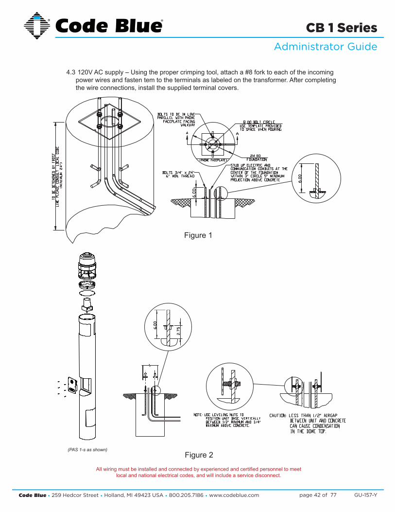
CB 1 SeriesAdministrator Guide
4.3 120V AC supply – Using the proper crimping tool, attach a #8 fork to each of the incoming power wires and fasten tem to the terminals as labeled on the transformer. After completing the wire connections, install the supplied terminal covers.
Figure 1
Figure 2(PAS 1-s as shown)
All wiring must be installed and connected by experienced and certified personnel to meetlocal and national electrical codes, and will include a service disconnect.

Code Blue • 259 Hedcor Street • Holland, MI 49423 USA • 800.205.7186 • www.codeblue.com GU-157-Ypage 43 of 77
CB 1 SeriesAdministrator Guide
24 NIghtCharge® Installation Instructions CAUTION: Do NOT apply power to the unit until all other conditions are made. See Step 6.
IMPORTANT: All wiring shall comply with national and local codes governing this installation. It is the responsibility of the installer to ensure these conditions are complied with.
1.0 SUPPLY WIRING
1.1 Pulling the power wires – Wire should be a minimum of 14 AWG and be pulled into the unit, leaving a minimum of two feet of wire from the opening of the conduit.
1.2 Pulling the communications wire (if needed) – Communications wire must be shielded phone line. The phone line must be pulled into the unit using a separate conduit from the power, and run to extend a minimum of two feet out of the phone opening.
2.0 CONNECT THE PHONE LINE (if needed) – See phone installation instructions.
3.0 OPTIONAL DIGITAL TRANSCEIVER (Model CB 1)
3.1 Remove GSM digital panel assembly from carton and hang over mounting plate inside unit behind phone opening.
3.2 The antenna is installed inside the dome top assembly at the factory.
NOTE: Dome top assembly may need to be rotated so antenna is positioned to achieve best signal.
3.3 Attach antenna cable male TNC fitting to the GSM enclosure female TNC fitting.
3.4 Attach the GSM positive Red wire to terminal strip screw #8 location and the negative Black wire to terminal strip location #5.
3.5 Attach the phone wires from the GSM assembly to terminals 1 and 2 on the IA4100 4 pin connector.
3.6 Set up GSM card. Refer to GSM digital set up instructions.
4.0 OPTIONAL DIGITAL TRANSCEIVER
4.1 Remove GSM digital housing assembly from carton and mount assembly to the pole using banding provided.
4.2 The antenna is installed to the 2-gang bell box at the factory. Mount the antenna as-sembly to the pole using the banding provided. Assembly may need to be rotated to achieve best signal.
4.3 Attach antenna cable male TNC fitting to the GSM enclosure female TNC fitting.
4.4 Attach the GSM positive red wire to terminal strip screw #8 location and the negative black wire to terminal strip location #5.
Code Blue • 259 Hedcor Street • Holland, MI 49423 USA • 800.205.7186 • www.codeblue.com GU-157-Ypage 44 of 77
CB 1 SeriesAdministrator Guide
4.5 Attach the phone wires from the GSM assembly to terminals 1 and 2 on the IA4100 4 pin connector.
4.6 Set up GSM card. Refer to GSM digital set up instructions.
5.0 CONNECT THE POWER WIRES
5.1 Make the connections – First, locate the grounding lug and connect the ground wire, leaving a minimum of six inches of slack. Second, using #8 forks, connect the power wires.
5.2 Using 115V AC supply: Connect the colored (hot) wire to the terminal screw furthest to the left (#1) on the terminal strip. Connect the white (neutral) wire to the terminal screw second to the left (#2) on the terminal strip.
5.3 Higher voltage supply: If the unit was ordered for a higher voltage, a multi-tap trans-former will be located at the top of the electrical panel. Be sure to connect your power wires to the correct terminal screws on the top of the transformer as labeled. Complete the connection by attaching the terminal cover that is supplied.
IMPORTANT: If the power is applied to the incorrect terminal screws, damage will occur to the unit. This damage will NOT be covered by any Code Blue warranty.
6.0 INSTALL THE BATTERY
IMPORTANT: Batteries MUST be fully bench charged before installation.
6.1 Place the battery into the unit – The battery should be placed in the bottom of the unit (in a CB 1 or CB 9 unit the battery shelf will need to be set in place first).
6.2 Connect the wires – First connect the blue wire to the positive lug on the battery, then connect the black wire to the negative lug.
7.0 APPLY POWER
7.1 Once power is applied, the unit will start the charging process.

Code Blue • 259 Hedcor Street • Holland, MI 49423 USA • 800.205.7186 • www.codeblue.com GU-157-Ypage 45 of 77
CB 1 SeriesAdministrator Guide
25 Solar and WindAssist™ Installation Instructions IMPORTANT NOTICE
The following list is provided as a checklist for items required prior to installation or items that will be required on installation site:1. Batteries must be FULLY bench charged before installation.2. A local cellular dealer must provide a SIM card before unit can place calls.3. Hand/Powered tools, including torque wrench, truck or mechanical lift for the CB 1 unit.4. At least two persons and ladders for attaching support collar, adjusting solar panel, etc.
1.0 FOUNDATION – (see Anchor Bolt Installation Instructions)
2.0 SET THE UNIT
2.1 Turn one set of nuts and washers onto the anchor bolts – After the foundation has set, turn one set of nuts followed by one set of washers onto the anchor bolts. Set the nuts such that the lowest washer is about 2½ inches above the concrete and at an even height. To accomplish this, use a small level and check from front to back, side to side and diagonally. These nuts are NOT adjustable after the unit is in place. The bottom edge of the Code Blue unit will be ½-inch above the concrete when installed.IMPORTANT: The leveling of the bottom nuts is crucial to the leveling of the unit. A small error in the adjustment of these will be magnified after installation.IMPORTANT: A ½-inch minimum air gap is required between the foundation and the unit. Moisture problems may result if this condition is not complied with.
2.2 Set the Code Blue unit on the anchor bolts – Align the phone plate in the desired direction and lift the Code Blue unit over the anchor bolts. The unit may be lifted using the I-bolt provided and screwed into one of the solar threaded holes used to mount the solar panel. Note that the unit weighs approximately 400 pounds. Use appropriate lifting materials and methods to avoid possible injury and/or damage.
2.3 Secure the Code Blue unit – Access the mounting studs through the door on the side of the unit, place the second set of washers and nuts on the studs and tighten the mounting nuts onto the anchor bolts. This may be more convenient if a long socket, extension and universal joint is used to tighten the hardware.
3.0 INSTALL THE SOLAR PANEL AND WIND GENERATOR
3.1 Adjustable universal mount
3.1.1 Attach the aluminum pole – Place a combination washer (rubber, then metal) on each of the three 5/8 bolts with Loctite treated threads. Attach the pole to the top of the unit. See Fig. 1.NOTE: Completely coat Loctite around the threads. Loctite MUST dry for 24 hours before being exposed to moisture.NOTE: Each time the bolts are removed, they must be retreated with the Loctite PST. CAUTION: Loctite PST is a skin irritant – use the enclosed rubber gloves to treat the threads. Dispose of gloves when completed.
SOLAR BOLLARD
GASKET
SOLAR COLLARRUBBER WASHER
METAL WASHER
HEX BOLT
APPLY LOCTITETO THREADS OF NUT
APPLY LOCTITE TOTHREADS OF BOLT
Figure 1
Code Blue • 259 Hedcor Street • Holland, MI 49423 USA • 800.205.7186 • www.codeblue.com GU-157-Ypage 46 of 77
CB 1 SeriesAdministrator Guide
3.1.2 Attach the aluminum bracket to the solar panel – Use the four 3/8 bolts and nuts and four 3/8 washers provided. Fish the pull wire out of the pull box to facilitate pulling the solar and wind generator wires into the unit for connection.
3.1.3 Mount and position the solar panel – Slide the aluminum bracket sleeve over the pole. The sleeve will rest on the collar of the aluminum pole just above the pull box. Point the solar panel due south and securely tighten the two 3/8 set-screws. Feed the power and antenna wires through the open hole in the bottom of the pull box. Attach the connector with the supplied lock nut and allow the wires to hang out of the box.
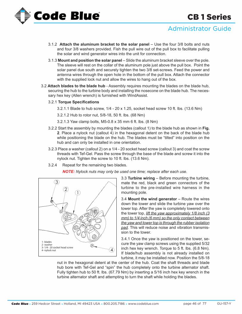
3.2 Attach blades to the blade hub - Assembly requires mounting the blades on the blade hub, securing the hub to the turbine body and installing the nosecone on the blade hub. The neces-sary hex key (Allen wrench) is furnished with WindAssist.3.2.1 Torque Specifications
3.2.1.1 Blade to hub screw, 1/4 - 20 x 1.25, socket head screw 10 ft. lbs. (13.6 Nm)3.2.1.2 Hub to rotor nut, 5/8-18, 50 ft. lbs. (68 Nm)3.2.1.3 Yaw clamp bolts, M5-0.8 x 35 mm 6 ft. lbs. (8 Nm)
3.2.2 Start the assembly by mounting the blades (callout 1) to the blade hub as shown in Fig. 2. Place a nylock nut (callout 4) in the hexagonal detent on the back of the blade hub while positioning the blade on the hub. The blades must be “tilted” into position on the hub and can only be installed in one orientation.
3.2.3 Place a washer (callout 2) on a 1/4 - 20 socket head screw (callout 3) and coat the screw threads with Tef-Gel. Pass the screw through the base of the blade and screw it into the nylock nut. Tighten the screw to 10 ft. lbs. (13.6 Nm).
3.2.4 Repeat for the remaining two blades. NOTE: Nylock nuts may only be used one time; replace after each use.
3.3 Turbine wiring – Before mounting the turbine, mate the red, black and green connectors of the turbine to the pre-installed wire harness in the mounting pole.3.4 Mount the wind generator – Route the wires down the tower and slide the turbine yaw over the tower top. After the yaw is completely lowered onto the tower top, lift the yaw approximately 1/8 inch (3 mm) to 1/4 inch (6 mm) so the only contact between the yaw and tower top is through the rubber isolation pad. This will reduce noise and vibration transmis-sion to the tower. 3.4.1 Once the yaw is positioned on the tower, se-cure the yaw clamp screws using the supplied 5/32 inch hex key wrench. Torque to 5 ft. lbs. (6.8 Nm). If blade/hub assembly is not already installed on turbine, it may be installed now. Position the 5/8-18
nut in the hexagonal detent at the center of the hub. Coat the shaft threads and blade hub bore with Tef-Gel and “spin” the hub completely onto the turbine alternator shaft. Fully tighten hub to 50 ft. lbs. (67.79 Nm) by inserting a 5/16 inch hex key wrench in the turbine alternator shaft and attempting to turn the shaft while holding the blades.
3
12
4
1- blades2- washer3- 1/4 - 20 socket head screw4- nylock nut

Code Blue • 259 Hedcor Street • Holland, MI 49423 USA • 800.205.7186 • www.codeblue.com GU-157-Ypage 47 of 77
CB 1 SeriesAdministrator Guide
3.4.2 Snap the nosecone into position over the outside edges of the blade hub.3.4.3 Make sure all three edges of the nosecone snap over the edge of the blade hub. After
installation tug on the nosecone to make sure it is securely attached.3.5 Fish the wires into the unit and connect them to the battery – Use the existing pull wire
and attach the solar panel, wind generator and antenna wires to pull down into the unit. Once the wires are into the unit, separate them. Attach the supplied forks to each black and red wire. The green wire should be attached to the existing ground lug on the bottom of the panel. One set of wires will have white electrical tape approximately 8-10 inches from the end. These are the solar panel wires.
3.6 Attach the solar panel wires – Connect the red wire to the solar charge controller on the positive (+) lug and the black wire on the negative (-) lug. These lugs are under the sunshine icon (See Figure 3).
3.7 Attach the wind generator wires – Connect the red wire to the center screw terminal on the stop switch. Connect the black wire to the same screw terminal the existing black wire is connected to (See Figure 3). 3.7.1 When the stop switch is pushed towards the panel the unit is in charging mode.3.7.2 When the stop switch is centered, it is not charging and the blades are in a free spin mode. 3.7.3 When the stop switch is pulled toward the access door, the blades will stop for maintenance.
4.0 INSTALL THE BATTERIES
NOTE: Batteries must be FULLY bench charged before installation.
WARNING: Reversing the battery wires (reversed polarity) will cause damage to the solar charge controller, wind generator GSM and IP wireless circuits and is NOT covered by the warranty.
4.1 Place the batteries into the unit – Insert the battery shelf plates into the bottom access door. One battery should be placed on each shelf.
4.2 Connect the wires – Connect the large gauge wires with yellow rings to the bottom battery along with the smaller gauge blue ringed wires. Connect the red wires to the positive (+) lugs on the batteries, then connect the black wires to the negative (-) lugs. Install the second bat-tery shelf plate and insert the top battery. Connect the small gauge yellow ringed wires to the battery. Connect the red wire to the positive (+) lugs on the batteries, then connect the black wire to the negative (-) lugs (See Figure 4).
5.0 INSTALLING THE GSM CELLULAR UNIT
NOTE: A local cellular dealer must provide a SIM card before it can place calls.5.1 Installation5.1.1 Remove the GSM unit from its shipping box.

Code Blue • 259 Hedcor Street • Holland, MI 49423 USA • 800.205.7186 • www.codeblue.com GU-157-Ypage 48 of 77
CB 1 SeriesAdministrator Guide
5.1.2 Use a small Phillips screwdriver to remove the SIM cover screw that is closest to the edge of the chassis. Loosen the second SIM screw slightly, rotate the cover 180 degrees, and re-tighten the second SIM screw slightly to keep the SIM compartment open (See Figure 5).
5.1.3 Orient the SIM to match the marking in the SIM compartment (the notched part of the SIM should be near the outer edge of the GSM unit). Insert the SIM into its receptacle (a small needle-nosed pliers can be helpful). Loosen the SIM cover screw slightly, rotate the SIM cover 180 degrees to its closed posi-tion and tighten both SIM cover screws.5.1.4 Copy the unit’s IMEI and Serial Number on the back for the cellular carrier before remounting the unit to the hanger plate.5.1.5 Attach the antenna to the GSM unit.5.1.6 Be sure that the VOICE/DATA switch is in the “VOICE” position.
5.1.7 Connect power to the GSM unit.5.1.8 Connect the RJ-11 cable to the FXS port on the rear of the GSM unit.
NOTE: The FXO port is not used; see Figure 6
5.1.9 Mount the GSM unit on the plate behind the phone with the mounting plate provided.6.0 NMO MOUNT ANTENNA ASSEMBLY
6.1 Insert MTPM assembly through 5/8” mount plate hole and tighten securely with lock washer and hex nuts provided.
6.2 Use one seal gasket for watertight seal around 3/4” brass mount.
6.3 Attach antenna base securely to mount, then use an N-type connector to connect the mount to the cable.
6.4 See Figure 7 for antenna parts assembly. coax
MTMP mount
brass mount
mount plate
dual-band antenna
Figure 5
Figure 6
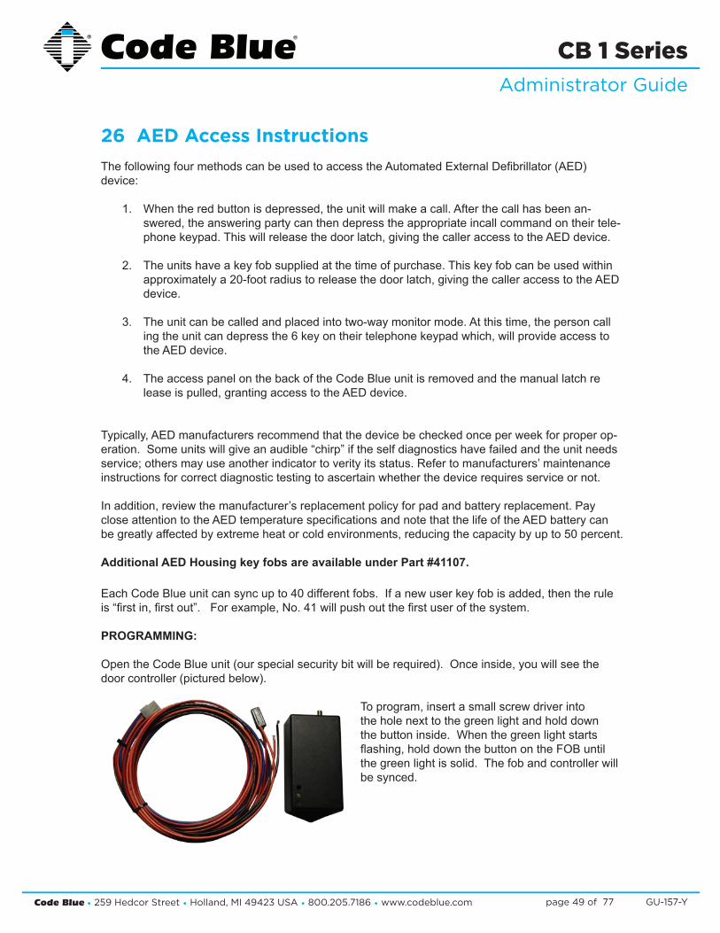
Code Blue • 259 Hedcor Street • Holland, MI 49423 USA • 800.205.7186 • www.codeblue.com GU-157-Ypage 49 of 77
CB 1 SeriesAdministrator Guide
26 AED Access Instructions The following four methods can be used to access the Automated External Defibrillator (AED) device:
1. When the red button is depressed, the unit will make a call. After the call has been an- swered, the answering party can then depress the appropriate incall command on their tele- phone keypad. This will release the door latch, giving the caller access to the AED device.
2. The units have a key fob supplied at the time of purchase. This key fob can be used within approximately a 20-foot radius to release the door latch, giving the caller access to the AED device.
3. The unit can be called and placed into two-way monitor mode. At this time, the person call ing the unit can depress the 6 key on their telephone keypad which, will provide access to the AED device.
4. The access panel on the back of the Code Blue unit is removed and the manual latch re lease is pulled, granting access to the AED device.
Typically, AED manufacturers recommend that the device be checked once per week for proper op-eration. Some units will give an audible “chirp” if the self diagnostics have failed and the unit needs service; others may use another indicator to verity its status. Refer to manufacturers’ maintenance instructions for correct diagnostic testing to ascertain whether the device requires service or not.
In addition, review the manufacturer’s replacement policy for pad and battery replacement. Pay close attention to the AED temperature specifications and note that the life of the AED battery can be greatly affected by extreme heat or cold environments, reducing the capacity by up to 50 percent.
Additional AED Housing key fobs are available under Part #41107.
Each Code Blue unit can sync up to 40 different fobs. If a new user key fob is added, then the rule is “first in, first out”. For example, No. 41 will push out the first user of the system.
PROGRAMMING:
Open the Code Blue unit (our special security bit will be required). Once inside, you will see the door controller (pictured below).
To program, insert a small screw driver into the hole next to the green light and hold down the button inside. When the green light starts flashing, hold down the button on the FOB until the green light is solid. The fob and controller will be synced.

Code Blue • 259 Hedcor Street • Holland, MI 49423 USA • 800.205.7186 • www.codeblue.com GU-157-Ypage 50 of 77
CB 1 SeriesAdministrator Guide
27 S-1000 & S-1050 Installation Instructions
M3159-R/BKRED
BLACK
POSITIVE (12-24V DC or AC)
COMMON (GROUND)
YELLOW (FLASH MODE)
M3159-Y/Y
DRY CONTACTCLOSED = "ON"
YELLOW (FLASH MODE)
CAUTION: REMOVE ALL POWER FROM UNIT BEFORE SERVICING.
ATTENTION: WHEN REPLACING A BEACON/STROBE ON THE MODEL CB 5 SERIES ONLY, MOUNTING SCREW THREADS MUST BE COATED TO PREVENT WATER LEAKAGE INTO THE UNIT.
OPERATION
To activate the LEDs in the PRIMARY-STEADYBURN MODE, connect the BLACK and RED wires to 12-24 volts AC or DC.
When in PRIMARY-STEADYBURN MODE, to change the LEDs to SECONDARY-FLASH MODE, connect both YELLOW control wires together (i.e., CLOSED = ON).
PHOTOCELL FEATURE (S-1050 MODEL)
The Steadyburn Mode will be ON in dark or night ambient environments and OFF in bright or daylight ambient environments. The S-1050 LED Beacon/Strobe has two built-in photo response features: (a) dawn/dusk transition delay of 15-30 minutes and (b) transient light acknowledgement delay of at least 3 minutes.
NOTE: Instructions pertain to Model S-1000 LED Beacon/Strobe andModel S-1050 LED Beacon/Strobe only

Code Blue • 259 Hedcor Street • Holland, MI 49423 USA • 800.205.7186 • www.codeblue.com GU-157-Ypage 51 of 77
CB 1 SeriesAdministrator Guide
PROGRAMMING PRIMARY & SECONDARY MODES
1. Remove power from unit.2. Short the Yellow wires together.3. Restore power to the unit and wait until the unit begins to flash. Once the unit begins to flash,
remove the short. The unit will alternately demonstrate the Secondary-Flash Mode and Primary-Steadyburn Mode that will be displayed during operation. For approximately 4 seconds the Secondary-Flash Mode will be demonstrated, followed by the Primary-Steadyburn Mode.
4. To select the next mode of operation, momentarily short the yellow wires. The unit will cycle to the next mode in the list above.
5. There are seven Flash Modes and three Steadyburn Modes combinations to choose from.6. When you reach the desired mode of operation, remove power from the unit. You MUST leave
power disconnected for 20 seconds BEFORE reapplying. When power is reapplied, the unit will operate as programmed above.
NOTE: If you do not leave power disconnected for 20 seconds before reapplying power, the light will default to Program Mode.
MODE NUMBER PRIMARY-STEADYBURN MODE SECONDARY-FLASH MODE
1 High Single - 60 FPM
2 OFF Single - 60 FPM
3 Low Single - 60 FPM
4 High Single - 150 FPM
5 OFF Single - 150 FPM
6 Low Single - 150 FPM
7 High Single - 375 FPM
8 OFF Single - 375 FPM
9 Low Single - 375 FPM
10 High Neobe - 75
11 OFF Neobe - 75
12 Low Neobe - 75
13 High Neobe - 150
14 OFF Neobe - 150
15 Low Neobe - 150
16 High Double - 125
17 OFF Double - 125
18 Low Double - 125
19 High Double - 250
20 OFF Double - 250
21 Low Double - 250
INPUT VOLTAGE RANGE: 12-24V AC or DC
TEMPERATURE RATING: -400 C to +650 C (-400 F to 1490 F)
TYPICAL POWER CONSUMPTION AT 250C
Voltage Flash Mode Steady Mode - High
12V DC 0.24 A Max 0.24 A
24V DC 0.12 A Max 0.12 A
12V AC 1.1 A rms Max 0.53 A rms
24V AC 0.22 A rms Max 0.22 A rms
NOTE: Average current draw in Flash Mode will vary by selected Flash Mode. The above maximum amperage draw is stated at Single 60 FPM.
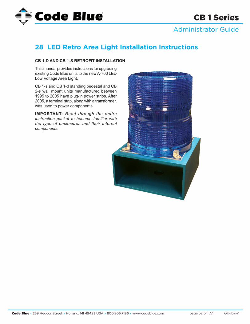
Code Blue • 259 Hedcor Street • Holland, MI 49423 USA • 800.205.7186 • www.codeblue.com GU-157-Ypage 52 of 77
CB 1 SeriesAdministrator Guide
28 LED Retro Area Light Installation Instructions
CB 1-D AND CB 1-S RETROFIT INSTALLATION
This manual provides instructions for upgrading existing Code Blue units to the new A-700 LED Low Voltage Area Light.
CB 1-s and CB 1-d standing pedestal and CB 2-s wall mount units manufactured between 1995 to 2005 have plug-in power strips. After 2005, a terminal strip, along with a transformer, was used to power components.
IMPORTANT: Read through the entire instruction packet to become familiar with the type of enclosures and their internal components.

Code Blue • 259 Hedcor Street • Holland, MI 49423 USA • 800.205.7186 • www.codeblue.com GU-157-Ypage 53 of 77
CB 1 SeriesAdministrator Guide
CB 1-S COMPONENT NAMES & ENCLOSURE LOCATIONS
To assist with identifying the major electrical components of the CB 1-s free-standing pedestals, callouts are depicted in the photo and mirrored illustration below.
REQUIRED TOOLS
• Zip ties (short & long assortment)• Crimp on wire forks (18 gauge)• Code Blue security bit & driver• #2 Philips screwdriver• 90° drill and drill bits• Taps for #6 screws• Digital volt meter• Conduit punch• Wire cutters• 10-foot ladder• Crimpers
Strobe orBeacon/Strobe
70-watt Area LightHPS or Metal Halide
Phone Faceplate Light Bar
Faceplate(connected to speakerphone
electronics)
Power Panel
Transformer or Power Strip
Access Door
Fig. 1
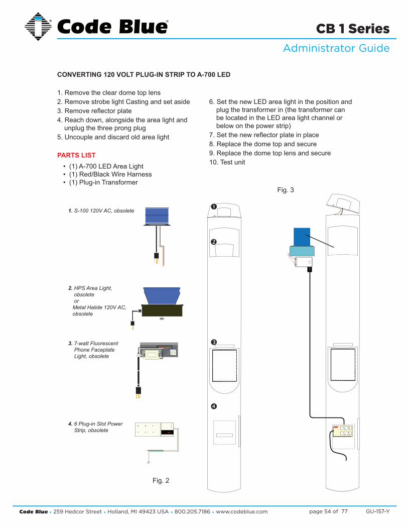
Code Blue • 259 Hedcor Street • Holland, MI 49423 USA • 800.205.7186 • www.codeblue.com GU-157-Ypage 54 of 77
CB 1 SeriesAdministrator Guide
1. Remove the clear dome top lens2. Remove strobe light Casting and set aside3. Remove reflector plate4. Reach down, alongside the area light and
unplug the three prong plug5. Uncouple and discard old area light
PARTS LIST• (1) A-700 LED Area Light• (1) Red/Black Wire Harness• (1) Plug-in Transformer
6. Set the new LED area light in the position and plug the transformer in (the transformer can be located in the LED area light channel or below on the power strip)
7. Set the new reflector plate in place8. Replace the dome top and secure9. Replace the dome top lens and secure10. Test unit
�
�
�
�1. S-100 120V AC, obsolete
2. HPS Area Light, obsolete
orMetal Halide 120V AC, obsolete
3. 7-watt Fluorescent Phone Faceplate Light, obsolete
4. 6 Plug-in Slot Power Strip, obsolete
Fig. 2
Fig. 3
CONVERTING 120 VOLT PLUG-IN STRIP TO A-700 LED

Code Blue • 259 Hedcor Street • Holland, MI 49423 USA • 800.205.7186 • www.codeblue.com GU-157-Ypage 55 of 77
CB 1 SeriesAdministrator Guide
CALLOUTS
1. Low Voltage Strobe or LED Beacon/Strobe 2. HPS or Metal Halide fixture, 120V AC only3. LED Faceplate Light 4. Faceplate/speakerphone electronics5. Power Panel w/Terminal JBox Block & 120-
24V Transformer6. Phone Line Surge Suppressor w/Ground Wire
for earth ground
PARTS LIST
• (1) A-700 LED Area Light• (1) Red/Black Wire Harness
The following instructions pertain to modifying high voltage HPS/Metal Halide fixtures to A-700 LED low voltage area light
1. Disconnect power to the unit2. Remove Dome Top Lens, then loosen the
three thumb screws on the lower inside edge of the metal casting
3. Lift casting and unplug strobe light wiring4. Secure wires, so they don’t fall down inside
the unit5. Lift reflector plate from enclosure6. Lift light fixture, locating the power cable and
unplug; remove light out of the unit7. Disconnect HPS/Metal Halide light power
cable from the 120 volt side of the transform-ers
8. Grab the power cable at the top of the unit and cut the zip tie holding it to the cross member
9. Fully remove cable out of unit10. Install the new LED area light with a plug-in
wire harness11. These wires will connect to the terminal strip
as illustrated in the wiring diagram12. Replace reflector plate and reconnect the
strobe light13. Line up the casting and tighten thumb
screws14. Replace clear lens and secure with button
head screws removed earlier14. WIRING: Follow the low voltage wiring
diagram. The red wire goes on terminal #4 and black to terminal #7 as shown in Wire Diagram 3.
15. Reapply power and test
UPGRADING CURRENT AREA LIGHT TO A-700 LED
�
�
�
�
�
Fig. 4

Code Blue • 259 Hedcor Street • Holland, MI 49423 USA • 800.205.7186 • www.codeblue.com GU-157-Ypage 56 of 77
CB 1 SeriesAdministrator Guide
29 PoE Installation Instructions
2
802.3at Switch
LAN 2LAN 1WANPoE PAS
ControlAux portsPAS
Audio+ -+ -Power | Battery
S-550 S1000
Ethernet
1
IP5000 Connector Side
43b
3
DATA – PoE+DATA
12 V DC
LED Faceplate Light Bar
2Second: Manifold fused red lead and black wires are secured to spring cage connector on the PoE+ Splitter. SEE DIAGRAM
Third: Connect the DATA cable RJ-45 from the Splitter “DATA” to the IP5000 WAN PoE port.
Voltage Selector Switch on the back must be in the 12V DC position
3
4
Fourth: Plug in the Ethernet PoE Cat 5e Cable to Data+PoE Input jack on the Splitters.Upon PoE Negotiation with the PoE switch port, power will be granted to the Splitter, and the indicator along with the device attached will turn on.
CAT5e < 3ft
in out GRD
3ftCat5e
CustomerCat5e
A-700
Electcial Modes 12VDC Amps WattageInRush (I) 2.00 24InRush Avg 0.40 4.8
Standby 0.55 6.6Talk - In Call 0.78 9.36
Grounding:
Should a ground be needed, there’s a ground screw on the enclosure with grounding logo next to it. When the splitter is mounted to the mounting bracket the bracket becomes the ground to the chassis of the enclosure, however local codes may require a ground wire be attached to the screw in order to comply.
When connecting PoE to the unit’s internal ground, make sure the unit itself is grounded to an outside local ground.
3b
12V DC switch positionfavors the DATA – PoE+
side of the module
DC Power Out
DAT
AD
ATA
+Po
E+
PoE Ack
CBXXXX PoE Splitter
1.00
1.37
1First: Electrical connections, All 4 Code Blue devices should to be connected to the 5 place manifold

Code Blue • 259 Hedcor Street • Holland, MI 49423 USA • 800.205.7186 • www.codeblue.com GU-157-Ypage 57 of 77
CB 1 SeriesAdministrator Guide
30 Blank Ring Installation Instructions Code Blue has blank Mounting Rings available as optional features for its 1 Series Pedestal Help Points® (CB 1-w not included). Designed in three varieties, these rings allow a customer to internally and externally mount third party communication and security equipment to their unit to enhance con-nectivity and functionality.
INSTALLATION:
All Rings: CB 1-e and CB 1-s (including Public Address and AED Housing Options)
TOOLS REQUIRED:
• Allen wrenches • Security bit • Ladder (if retrofitting) • Mounting Ring with screws
INSTRUCTIONS:
• If applicable, remove dome top assembly using security bit prior to installation. New style dome top assembly (part #40259) is required to access installation screws on Mounting Ring. Locate and install the three ½ x 1-inch hex Allen screws from the inside of the Mount ing Ring using the Allen wrench. Be sure the Allen screws do not extend beyond the outside of the ring.
• Install the mounting ring on top of the unit. Rotate to desired position. o NOTE: If retrofitting existing unit with three countersunk holes near the top of the unit, the Mounting Ring may be rotated to align the clearance holes with holes in the unit. The three countersunk screws and nuts provided may be used to cover these holes. The three Allen screws MUST be used to secure the mounting ring to the unit. o NOTE: If installed on a unit with an Overhead Camera Mount, the Mounting Ring should be mounted on top of the Overhead Camera Mount ring.
• Verify Mounting Ring is evenly positioned to ensure gasket seal is seated appropriately 360 degrees.
• Apply downward pressure while simultaneously tightening the three ½-inch set screws until Mounting Ring is snug against the inside of the unit.
• Install Beacon/Strobe Dome Top Assembly.
POWER:
• The 1 Series power configuration is only intended to support the electronics Code Blue installs as standard equipment.
*IF A CUSTOMER INSTALLS THEIR OWN POWER SOURCE, IT WILL VOID THE ENCLOSURE’S UL LISTING.
Please contact Customer Service with any questions or concerns.Email: [email protected]: 616-392-8396, Opt. 2

Code Blue • 259 Hedcor Street • Holland, MI 49423 USA • 800.205.7186 • www.codeblue.com GU-157-Ypage 58 of 77
CB 1 SeriesAdministrator Guide
31 CB 1 Series Deck Mount Installation Instructions
1.0 DECK MOUNT FOUNDATION
1.1 Drill Deck Holes – Drill four holes through the deck or floor for the four 3/4” threaded rods. The holes should be aligned, using the template provided in such a way that the phone face-plate on the unit will face in the desired direction (see figure below).
1.2 Drill a fifth hole in the center to accommodate the conduit. 1.3 Position Upper Deck Plate – Position the first plate working from above the deck.
1.3.1 Thread a nut and washer on the end of each rod so that approximately six inches ex-tends beyond the base of the washer.
1.3.2 Insert each rod through the top side of the plate, plate gasket, and down through the four holes in the deck.
NOTE: The top of the plate is the side with the tapered edge.
1.4 Position Lower Deck Plate – Position the second plate working from below the deck. Have another worker hold the upper plate and rods in place from above the deck. 1.4.1 Place the second plate gasket and then the second plate over the threaded rods. 1.4.2 Secure the second plate with nuts and washers provided. If required, readjust the nuts
so that six inches of the rods are above the top of the upper plate (see figure below).1.5 Secure Lower Nuts – To prevent tampering, it is advisable to tack weld the lower nuts to the
threaded rod.
2.0 WIRING
2.1 Pull power and phone line through conduits – A minimum of two feet of wire must be avail-able from the conduit for electrical and communications wiring.
2.2 Conduit – Electrical and telephone line conduit is run through the deck and the center open-ings (two-inch diameter) of the upper and lower deck plates. A minimum of four inches and a maximum of six inches of conduit above the upper plate is required.
B B
CB 1 Base
3/4" THREADED ROD OF SUFFICENT LENGTH TO PASS THROUGH DECK
AND ALLOW A MINIMUM OF 6” ABOVE THE TOP DECK PLATE.
6.00
Ø14.00 DECK PLATE
PHONEFACEPLATEDIRECTION
ALLOW1/2" GAP FOR
VENTING
ELECTRICAL AND TELEPHONE
LINE CONDUIT
Ø8.00 BOLT CIRCLE

Code Blue • 259 Hedcor Street • Holland, MI 49423 USA • 800.205.7186 • www.codeblue.com GU-157-Ypage 59 of 77
CB 1 SeriesAdministrator Guide
--
/
32 CB 1-e and CB 1-s 24V or 120V Multi-Tap Power Brick Wiring (prior to 2015)
Product wiring diagram shown reasonably represents current offering and is intended to assist in component identification and service. Earlier product production may have different components and wiring connections. Reference the model and serial number from the unit ID tag and contact
manufacturer to confirm replacement part version and availability.

Code Blue • 259 Hedcor Street • Holland, MI 49423 USA • 800.205.7186 • www.codeblue.com GU-157-Ypage 60 of 77
CB 1 SeriesAdministrator Guide
LV Positive
LV Negative
--
/
33 CB 1-e and CB 1-s 24V or 120V Multi-Tap Power Brick Wiring
Product wiring diagram shown reasonably represents current offering and is intended to assist in component identification and service. Earlier product production may have different components and wiring connections. Reference the model and serial number from the unit ID tag and contact
manufacturer to confirm replacement part version and availability.
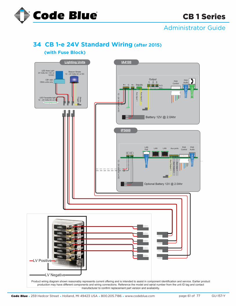
Code Blue • 259 Hedcor Street • Holland, MI 49423 USA • 800.205.7186 • www.codeblue.com GU-157-Ypage 61 of 77
CB 1 SeriesAdministrator Guide
34 CB 1-e 24V Standard Wiring (after 2015)
(with Fuse Block)
Product wiring diagram shown reasonably represents current offering and is intended to assist in component identification and service. Earlier product production may have different components and wiring connections. Reference the model and serial number from the unit ID tag and contact
manufacturer to confirm replacement part version and availability.
LV Positive
LV Negative
Beacon Strobe12 – 24 Volts AC or DC
LED Area Light24 Volts AC / DC or
12VDC
CB1 s&dCB2s units only
Lighting Units
Strobe
Trigger
LED Faceplate light12 – 24 Volts AC or DC
LANLANLANPoE
PASControlAux ports PAS
Audio
+ - + -
IP5000
Audio
Output
1
Optional Battery 12V @ 2.0Ahr
12–
24V
oltsA
CorD
C
Ethernet
Aux
Output2
Aux
input1
Aux
Output1
1
Inputs
Aux
input1
Aux
input2
Phone
line
Audio
Output
+- G +-
Output1 2 3
N.O.N.C.
PASControl
PASAudio
IA4100
Battery 12V @ 2.0Ahr12
–24
Volts
AC
orDC
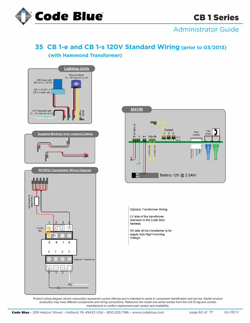
Code Blue • 259 Hedcor Street • Holland, MI 49423 USA • 800.205.7186 • www.codeblue.com GU-157-Ypage 62 of 77
CB 1 SeriesAdministrator Guide
35 CB 1-e and CB 1-s 120V Standard Wiring (prior to 03/2013)
(with Hammond Transformer)
Product wiring diagram shown reasonably represents current offering and is intended to assist in component identification and service. Earlier product production may have different components and wiring connections. Reference the model and serial number from the unit ID tag and contact
manufacturer to confirm replacement part version and availability.
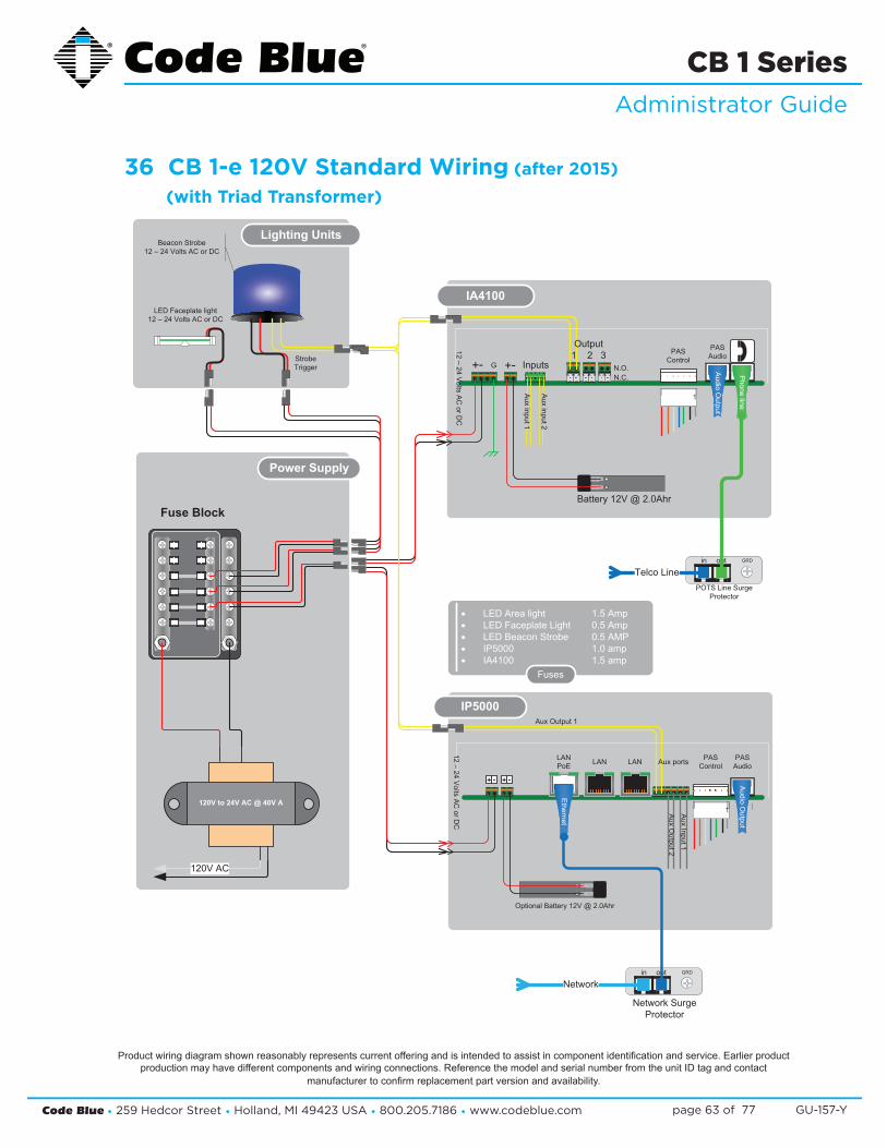
Code Blue • 259 Hedcor Street • Holland, MI 49423 USA • 800.205.7186 • www.codeblue.com GU-157-Ypage 63 of 77
CB 1 SeriesAdministrator Guide
36 CB 1-e 120V Standard Wiring (after 2015)
(with Triad Transformer)
Lighting Units
StrobeTrigger
LED Faceplate light12 – 24 Volts AC or DC
Power Supply
Fuse Block
in out GRD
Network SurgeProtector
in out GRD
POTS Line SurgeProtector
Network
Telco Line
1
InputsA
uxinput1
Aux
input2
Phone
line
Audio
Output
+- G +-
Output1 2 3
N.O.N.C.
PASControl
PASAudio
Battery 12V @ 2.0Ahr
12–
24V
oltsA
CorD
C
IA4100
LANLANLANPoE
PASControl
PASAudio
+ - + - Audio
Output
1
Optional Battery 12V @ 2.0Ahr
Ethernet
Aux
Output2
Aux
Input1
Aux Output 1
Aux ports
IP5000
12–
24V
oltsA
CorD
C
Beacon Strobe12 – 24 Volts AC or DC
· LED Area light 1.5 Amp· LED Faceplate Light 0.5 Amp· LED Beacon Strobe 0.5 AMP· IP5000 1.0 amp· IA4100 1.5 amp
Fuses
120V to 24V AC @ 40V A
120V AC
Product wiring diagram shown reasonably represents current offering and is intended to assist in component identification and service. Earlier product production may have different components and wiring connections. Reference the model and serial number from the unit ID tag and contact
manufacturer to confirm replacement part version and availability.
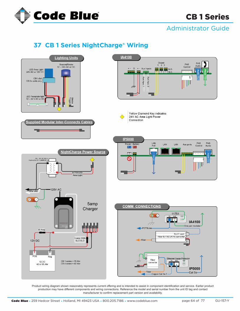
Code Blue • 259 Hedcor Street • Holland, MI 49423 USA • 800.205.7186 • www.codeblue.com GU-157-Ypage 64 of 77
CB 1 SeriesAdministrator Guide
37 CB 1 Series NightCharge® Wiring
and
/
Product wiring diagram shown reasonably represents current offering and is intended to assist in component identification and service. Earlier product production may have different components and wiring connections. Reference the model and serial number from the unit ID tag and contact
manufacturer to confirm replacement part version and availability.

Code Blue • 259 Hedcor Street • Holland, MI 49423 USA • 800.205.7186 • www.codeblue.com GU-157-Ypage 65 of 77
CB 1 SeriesAdministrator Guide
38 CB 1 Series with Public Address Wiring
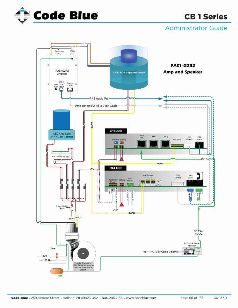
Code Blue • 259 Hedcor Street • Holland, MI 49423 USA • 800.205.7186 • www.codeblue.com GU-157-Ypage 66 of 77
CB 1 SeriesAdministrator Guide

Code Blue • 259 Hedcor Street • Holland, MI 49423 USA • 800.205.7186 • www.codeblue.com GU-157-Ypage 67 of 77
CB 1 SeriesAdministrator Guide
39 CB 1-w Standard Wiring
Product wiring diagram shown reasonably represents current offering and is intended to assist in component identification and service. Earlier product production may have different components and wiring connections. Reference the model and serial number from the unit ID tag and contact
manufacturer to confirm replacement part version and availability.
(Solar)
(NightCharge®)
-
4-u

Code Blue • 259 Hedcor Street • Holland, MI 49423 USA • 800.205.7186 • www.codeblue.com GU-157-Ypage 68 of 77
CB 1 SeriesAdministrator Guide
40 GSM Wireless Wiring Diagram
®
®
®
WIRELESS (NOT SUPPLIED BY CODE BLUE)
Product wiring diagram shown reasonably represents current offering and is intended to assist in component identification and service. Earlier product production may have different components and wiring connections. Reference the model and serial number from the unit ID tag and contact
manufacturer to confirm replacement part version and availability.

Code Blue • 259 Hedcor Street • Holland, MI 49423 USA • 800.205.7186 • www.codeblue.com GU-157-Ypage 69 of 77
CB 1 SeriesAdministrator Guide
41 CB 1-s with AED, Public Address and IP Wireless
FILENAME
DFB PAS IPWIRELESS WIRING.VSD
PAGE
1 OF 1
DRAWN BY
MIKE ROSE
Toroidal Transformer120 V AC @ 3.2 amps to
V AC 54./24./17.5/9.5380V A
120V AC
DFB1 w / PAS-IP w/Optional Wireless
24VA
C
75 watt Heating Element
120V AC
LED AREA Lite
LED Faceplatelight
Lighting
5 Amp
PAS Power Supply
1
LANLANLANPoE PAS
ControlAux portsPAS
Audio+ -+ -
Power & BatteryIP5000
in out GRDSurge Protector
Phone line
Aux 1Strobe
PASControl
Aux Outputs1 2 3
1
3
2
4
N.O.N.C.
AuxInputs
PASAudio
Aux
input2
Acc
Pw
r
1
Chassis
Ground
BatteryAccessoryPower
Aux
1S
trobe
Aux
input1
IA4100
in out GRDSurge Protector
Ethernet
Door Release Mech
Red / Blu: Door MechOrg / Org: Phones Aux Output #2
Red / Blk: Power 12 V DCBrn / Brn: Unused
Mag
DoorS
w
AED Door Release Circuit
InterconnectCable
Optional Battery for IP5000 and IA4100 is used incase of power failureoperations. Battery does not provide power for anything but the phone
PAS 1 Module
PAS1 G2Amplifier
PAS1 360°Speaker
Array
Optional IP Wireless / IP5000 Only
Secure Mesh™
Ethernet
24V ACInput
12 V DCoutput
Converter24V AC to12V DC @ 5A
AC to DC Converter
Product wiring diagram shown reasonably represents current offering and is intended to assist in component identification and service. Earlier product production may have different components and wiring connections. Reference the model and serial number from the unit ID tag and contact
manufacturer to confirm replacement part version and availability.
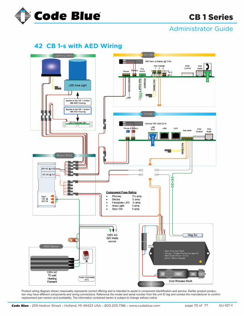
Code Blue • 259 Hedcor Street • Holland, MI 49423 USA • 800.205.7186 • www.codeblue.com GU-157-Ypage 70 of 77
CB 1 SeriesAdministrator Guide
Product wiring diagram shown reasonably represents current offering and is intended to assist in component identification and service. Earlier product produc-tion may have different components and wiring connections. Reference the model and serial number from the unit ID tag and contact the manufacturer to confirm replacement part version and availability. The information contained herein is subject to change without notice.
12V
12V
42 CB 1-s with AED Wiring
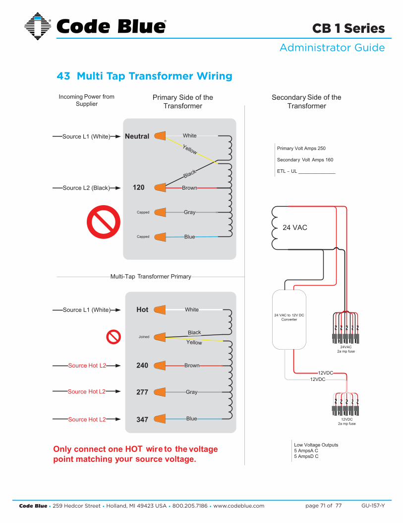
Code Blue • 259 Hedcor Street • Holland, MI 49423 USA • 800.205.7186 • www.codeblue.com GU-157-Ypage 71 of 77
CB 1 SeriesAdministrator Guide
43 Multi Tap Transformer Wiring
Primary Volt Amps 250
Secondar olt Amps 160
ETL – UL ______________
Low Voltage Outputs5 AmpsA C5 AmpsD C
24 VAC
24 VA 2V DCConverter
12VDC12VDC
12VDC2a mp fuse
24VAC2a mp fuse
Multi-Ta ransformer Primary
IncomingSupplier
Primary Side of theTransformer
SecondarTransformer
White
Yellow
Brown
Gray
Blue
Black
347
240
277
Hot
Joined
Source L1 (White)
Source
Source
Source
White
Black
Yellow
Brown
Blue
Gray
120
Neutral
Capped
Capped
Source L1 (White)
Source L2 (Black)
Only connect one HO ir he voltagepoint matchin ou ource voltage.
T w e to tg y r s
p T
Side of they
y V
Power from
Hot L2
Hot L2
Hot L2
toC 1
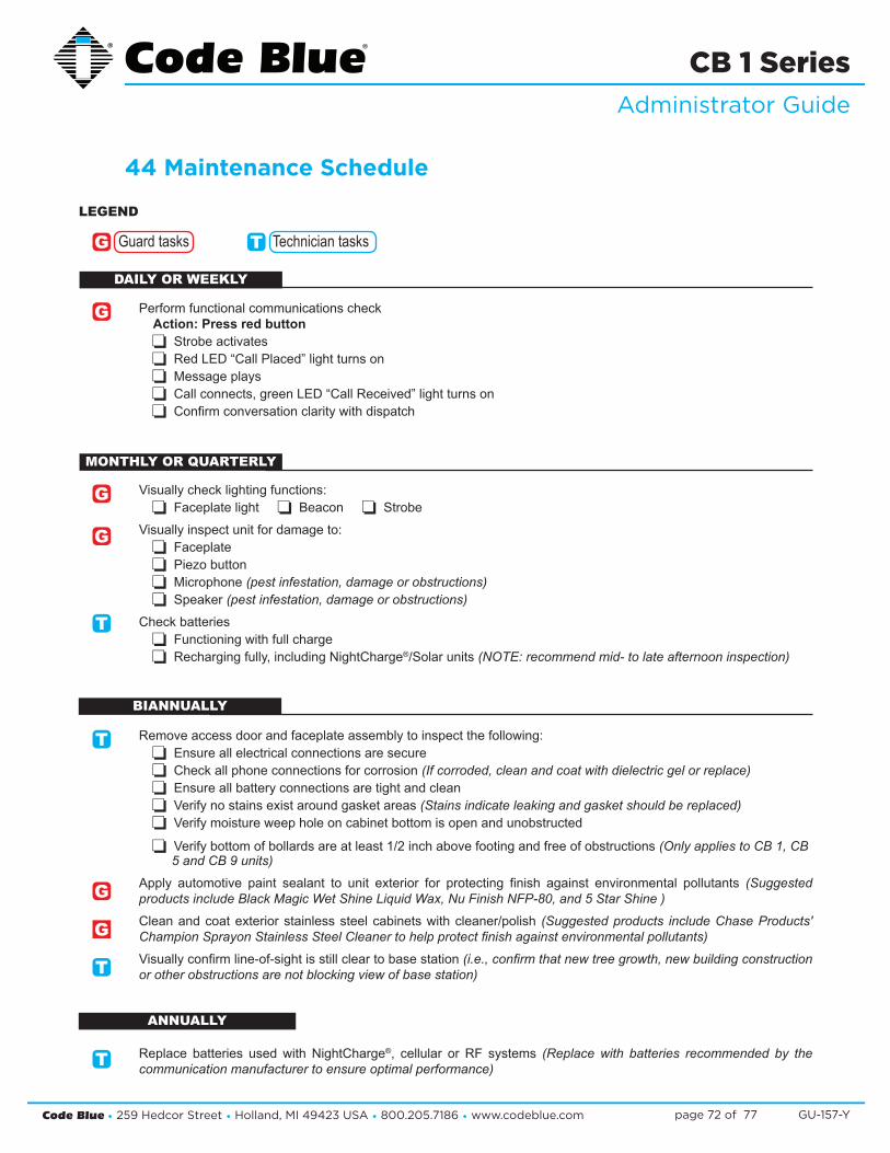
Code Blue • 259 Hedcor Street • Holland, MI 49423 USA • 800.205.7186 • www.codeblue.com GU-157-Ypage 72 of 77
CB 1 SeriesAdministrator Guide
44 Maintenance Schedule
Perform functional communications check Action: Press red button
Strobe activates Red LED “Call Placed” light turns on Message plays Call connects, green LED “Call Received” light turns on Confirm conversation clarity with dispatch
Visually check lighting functions: Faceplate light Beacon Strobe
Visually inspect unit for damage to: Faceplate Piezo button Microphone (pest infestation, damage or obstructions) Speaker (pest infestation, damage or obstructions)
Check batteries Functioning with full charge Recharging fully, including NightCharge®/Solar units (NOTE: recommend mid- to late afternoon inspection)
Remove access door and faceplate assembly to inspect the following: Ensure all electrical connections are secure Check all phone connections for corrosion (If corroded, clean and coat with dielectric gel or replace) Ensure all battery connections are tight and clean Verify no stains exist around gasket areas (Stains indicate leaking and gasket should be replaced) Verify moisture weep hole on cabinet bottom is open and unobstructed
Verify bottom of bollards are at least 1/2 inch above footing and free of obstructions (Only applies to CB 1, CB 5 and CB 9 units)
Apply automotive paint sealant to unit exterior for protecting finish against environmental pollutants (Suggested products include Black Magic Wet Shine Liquid Wax, Nu Finish NFP-80, and 5 Star Shine )
Clean and coat exterior stainless steel cabinets with cleaner/polish (Suggested products include Chase Products' Champion Sprayon Stainless Steel Cleaner to help protect finish against environmental pollutants)
Visually confirm line-of-sight is still clear to base station (i.e., confirm that new tree growth, new building construction or other obstructions are not blocking view of base station)
Replace batteries used with NightCharge®, cellular or RF systems (Replace with batteries recommended by the communication manufacturer to ensure optimal performance)
Guard tasks Technician tasks
LEGEND
G
BIANNUALLY
MONTHLY OR QUARTERLY
DAILY OR WEEKLY
G T
G
G
G
T
T
G
T
T
ANNUALLY
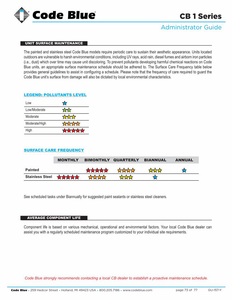
Code Blue • 259 Hedcor Street • Holland, MI 49423 USA • 800.205.7186 • www.codeblue.com GU-157-Ypage 73 of 77
CB 1 SeriesAdministrator Guide
MONTHLY BIMONTHLY QUARTERLY BIANNUAL ANNUAL
Painted êêêêê êêêê êêê êStainless Steel êêêêê êêêê êêê ê
The painted and stainless steel Code Blue models require periodic care to sustain their aesthetic appearance. Units located outdoors are vulnerable to harsh environmental conditions, including UV rays, acid rain, diesel fumes and airborn iron particles (i.e., dust) which over time may cause unit discoloring. To prevent pollutants developing harmful chemical reactions on Code Blue units, an appropriate surface maintenance schedule should be adhered to. The Surface Care Frequency table below provides general guidelines to assist in configuring a schedule. Please note that the frequency of care required to guard the Code Blue unit’s surface from damage will also be dictated by local environmental characteristics.
Low êLow/Moderate êêModerate êêêModerate/High êêêêHigh êêêêê
LEGEND: POLLUTANTS LEVEL
See scheduled tasks under Biannually for suggested paint sealants or stainless steel cleaners.
Component life is based on various mechanical, operational and environmental factors. Your local Code Blue dealer can assist you with a regularly scheduled maintenance program customized to your individual site requirements.
UNIT SURFACE MAINTENANCE
AVERAGE COMPONENT LIFE
SURFACE CARE FREQUENCY
Code Blue strongly recommends contacting a local CB dealer to establish a proactive maintenance schedule.
Code Blue • 259 Hedcor Street • Holland, MI 49423 USA • 800.205.7186 • www.codeblue.com GU-157-Ypage 74 of 77
CB 1 SeriesAdministrator Guide
45 CB 1-s with AED Access and Maintenance
The following methods can be used to access the Automated External Defibrillator (AED) device:
1. When the red button is depressed, the unit will make a call. After the call has been an- swered, the answering party can depress the 5 key on their telephone keypad. This will release the door latch, giving the caller access to the AED device.
2. The units have a key fob supplied at the time of purchase. This key fob can be used within a 20-foot radius to release the door latch, giving the caller access to the AED device.
3. The unit can be called and placed into two-way monitor mode. At this time, the person call ing the unit can depress the 6 key on their telephone keypad, which will provide access to the AED device.
4. The access panel on the back of the Code Blue unit is removed and the manual latch re- lease is pulled, granting access to the AED device.
Typically, AED manufacturers recommend that the device be checked once per week for proper op-eration. Some units will give an audible “chirp” if the self-diagnostics have failed and the unit needs service. Others may use another indicator to verity its status. Refer to manufacturer’s maintenance instructions for correct diagnostic testing to ascertain whether the device requires service or not.
In addition, review the manufacturer’s replacement policy for pad and battery replacement. Pay close attention to the AED temperature specifications and consider the life of the AED battery, which can be greatly affected by extreme heat or cold environments and reduce the capacity by up to 50 percent.

Code Blue • 259 Hedcor Street • Holland, MI 49423 USA • 800.205.7186 • www.codeblue.com GU-157-Ypage 75 of 77
CB 1 SeriesAdministrator Guide
46 Locating Unit Serial Numbers
Remove the access plate cover with the special security bit. The serial number will be listed on the manufacturer’s label located on the backside of the access plate cover (1).
1

Code Blue • 259 Hedcor Street • Holland, MI 49423 USA • 800.205.7186 • www.codeblue.com GU-157-Ypage 76 of 77
CB 1 SeriesAdministrator Guide
47 Warranty
Code Blue Corporation provides a limited warranty on this product. Refer to your sales agreement to establish the terms. In addition, Code Blue’s standard warranty language, as well as information regarding support for this product while under warranty, is available at www.codeblue.com/support.
In Case of Breakdown
In case of system breakdown, discontinue use and contact :
Tech Support at [email protected] or call 800-205-7186, option 3.
In Case of Abnormal Operation
If the unit emits smoke or an unusual smell, if water or other foreign material enters the enclosure, or if you drop the unit or damage the enclosure, power off the unit immediately and contact:
Code Blue Customer Service at [email protected] or call Customer Service at 800-205-7186, option 2.

Code Blue • 259 Hedcor Street • Holland, MI 49423 USA • 800.205.7186 • www.codeblue.com GU-157-Ypage 77 of 77
CB 1 SeriesAdministrator Guide
48 Download Information
Download Information
CSC-132-D
Main Location: www.codeblue.com/support/resources Code Blue now has a centralized location where you can find Installation, Setup, Information, Configuration and Operation instructions. 1. CB 1 Series Administrator Guide: www.codeblue.com/support/resources 2. CB 2 Series Administrator Guide: www.codeblue.com/support/resources 3. CB 4 Series Administrator Guide: www.codeblue.com/support/resources 4. CB 5 Series Administrator Guide: www.codeblue.com/support/resources 5. CB 6 Series Administrator Guide: www.codeblue.com/support/resources 6. CB 9 Series Administrator Guide: www.codeblue.com/support/resources 7. IA4100 Administrator Guide: www.codeblue.com/support/resources 8. IA3100 to IA4100 Upgrade Installation: www.codeblue.com/support/faq 9. IP5000 Administrator Guide: www.codeblue.com/support/resources 10. IP1500/2500 Administrator Guide: www.codeblue.com/support/resources 11. IA500 Administrator Guide: www.codeblue.com/support/resources 12. ToolVox® Administrator Guide (prior to Aug. 2014): www.codeblue.com/support/resources 13. ToolVox X3 Administrator Guide: www.codeblue.com/support/resources 14. Public Address Administrator Guide: www.codeblue.com/support/resources 15. Blue Alert® MNS User Guide: www.codeblue.com/support/resources 16. Blue Alert® EMS User Guide: www.codeblue.com/support/resources 17. Blue Alert® Mobile User Guide: www.codeblue.com/support/resources 18. IP1500 and IP2500 Firmware: www.codeblue.com/support/firmware 19. IP5000 Versions 1.X & 2.X Firmware: www.codeblue.com/support/firmware
For Legacy IA3100 Information: www.codeblue.com/support/resources These Guides should contain all the information needed for your application. If further information is required, please contact [email protected].