cavitation erosion resistance and wear mechanisms of...
TRANSCRIPT

Cavitation erosion resistance and wear mechanismsof active screen low temperature plasma nitridedAISI 410 martensitic stainless steelEspitia, L.A; Dong, Hanshan; Li, Xiaoying; Pinedo, C.E.; Tschiptschin, A.P.
DOI:10.1016/j.wear.2014.12.009
License:Other (please specify with Rights Statement)
Document VersionPeer reviewed version
Citation for published version (Harvard):Espitia, LA, Dong, H, Li, X, Pinedo, CE & Tschiptschin, AP 2014, 'Cavitation erosion resistance and wearmechanisms of active screen low temperature plasma nitrided AISI 410 martensitic stainless steel' Wear. DOI:10.1016/j.wear.2014.12.009
Link to publication on Research at Birmingham portal
Publisher Rights Statement:NOTICE: this is the author’s version of a work that was accepted for publication in Wear. Changes resulting from the publishing process,such as peer review, editing, corrections, structural formatting, and other quality control mechanisms may not be reflected in this document.Changes may have been made to this work since it was submitted for publication. A definitive version was subsequently published in Wear,DOI: 10.1016/j.wear.2014.12.009.
Eligibility for repository checked March 2015
General rightsUnless a licence is specified above, all rights (including copyright and moral rights) in this document are retained by the authors and/or thecopyright holders. The express permission of the copyright holder must be obtained for any use of this material other than for purposespermitted by law.
•Users may freely distribute the URL that is used to identify this publication.•Users may download and/or print one copy of the publication from the University of Birmingham research portal for the purpose of privatestudy or non-commercial research.•User may use extracts from the document in line with the concept of ‘fair dealing’ under the Copyright, Designs and Patents Act 1988 (?)•Users may not further distribute the material nor use it for the purposes of commercial gain.
Where a licence is displayed above, please note the terms and conditions of the licence govern your use of this document.
When citing, please reference the published version.
Take down policyWhile the University of Birmingham exercises care and attention in making items available there are rare occasions when an item has beenuploaded in error or has been deemed to be commercially or otherwise sensitive.
If you believe that this is the case for this document, please contact [email protected] providing details and we will remove access tothe work immediately and investigate.
Download date: 30. Jul. 2018

Author's Accepted Manuscript
Cavitation erosion resistance and wear me-chanisms of active screen low temperatureplasma nitrided AISi 410 martensitic stainlesssteel
L.A. Espitia, Hanshan Dong, Xiao-Ying Li, C.E.Pinedo, A.P. Tschiptschin
PII: S0043-1648(14)00378-0DOI: http://dx.doi.org/10.1016/j.wear.2014.12.009Reference: WEA101175
To appear in: Wear
Received date: 1 October 2014Revised date: 23 November 2014Accepted date: 3 December 2014
Cite this article as: L.A. Espitia, Hanshan Dong, Xiao-Ying Li, C.E. Pinedo, A.P.Tschiptschin, Cavitation erosion resistance and wear mechanisms of activescreen low temperature plasma nitrided AISi 410 martensitic stainless steel,Wear, http://dx.doi.org/10.1016/j.wear.2014.12.009
This is a PDF file of an unedited manuscript that has been accepted forpublication. As a service to our customers we are providing this early version ofthe manuscript. The manuscript will undergo copyediting, typesetting, andreview of the resulting galley proof before it is published in its final citable form.Please note that during the production process errors may be discovered whichcould affect the content, and all legal disclaimers that apply to the journalpertain.
www.elsevier.com/locate/wear

CAVITATION EROSION RESISTANCE AND WEAR MECHANISMS OF ACTIVE SCREEN LOW TEMPERATURE PLASMA NITRIDED AISI 410 MARTENSITIC
STAINLESS STEEL
L.A. Espitiaad*, Hanshan Dongb, Xiao-Ying Lib, C.E. Pinedoc, A.P. Tschiptschina. a Metallurgical and Materials Engineering Department, University of São Paulo , Av. Prof. Mello Moraes 2463, 05508-030 São Paulo, SP, Brazil. b School of Metallurgy and Materials, College of Engineering and Physical Sciences, The University of Birmingham, Edgbaston, Birmingham B15 2TT, United Kingdom. c C.E. Pinedo, Heat Tech Technology for Heat Treatment and Surface Engineering Ltd, Av. João XXIII, 1160, 08830-000 Mogi das Cruzes, SP, Brazil. d Engineering, Science and Technology Research Group, Mechanical Engineering Department, Cr 6 No 76-103, University of Córdoba, Montería Colombia. *Corresponding author, e-mail address: [email protected] Keywords: Expanded Martensite, Cavitation Erosion, Active Screen Plasma Nitriding, Mechanisms of Wear, Nanoindentation. Abstract Quenched and tempered AISI 410 martensitic stainless steel specimens were active screen plasma nitrided in a mixture of 75 % of nitrogen and 25 % of hydrogen during 20 hours at 400°C. The microstructure of the nitrided case was characterized by optical microscopy, scanning electron microscopy and microhardness measurements. The phases were identified by X-ray diffraction and the nitrogen content as a function of depth was measured using wavelength dispersive X-ray spectrometer coupled to SEM. Nanoindentation tests were carried out in order to assess hardness (H), Young modulus (E), H/E and H3/E2 ratios and the elastic recovery (We) of the nitrided layer. Cavitation erosion tests were carried out according to ASTM G32 standard during 20 hours, with periodical interruptions for registering the mass losses. Additional cavitation erosion tests were performed to identify the wear mechanisms in both specimens, through assessment of the evolution of the damage on the surface, in a scanning electron microscope. A ~28 µm thick, 1275 HV hard nitrided case formed at the surface of the martensitic stainless steel, composed of nitrogen supersaturated expanded martensite and hexagonal ε-Fe24N10 iron nitrides. The expanded martensite decreased 27 times the mass loss shown by the non-nitrided stainless steel and the erosion rate decreased from 2.56 mg/h to 0.085 mg/h. The increase in cavitation erosion resistance can be mainly attributed to the increase in hardness and to the elastic response of the expanded martensite. The non-nitrided specimen changed from initially ductile to brittle behavior, exhibiting two different modes of material detachment. The first mode was characterized by a great degree of plastic deformation, fatigue and ductile fracture. The second failure mode could be associated to brittle fracture by cleavage mechanisms. In contrast, the wear mechanism observed in the nitrided specimen was brittle fracture without evident plastic deformation.

1. Introduction Hydraulic components such as turbines, pumps, valves and pipes are known to be affected by cavitation erosion. This undesirable type of wear increases both the frequency of maintenance operation and the repairing costs. Most of the components submitted to cavitation are manufactured using stainless steels and many attempts to enhance its cavitation erosion resistance have been made. The introduction of nitrogen atoms using thermochemical treatments has been proved to be an effective way to enhance the wear resistance of stainless steels and an improvement in cavitation erosion resistance of stainless steels due to the increase in nitrogen content in solid solution by means of high temperature gas nitriding treatment has been reported by several authors [1,2,3]. Garzón et al. showed that nitrogen contents between 0.65 and 1.15 wt. % decreased between 7.6 and 23.3 times the erosion rate of UNS S31803 duplex stainless steel [2]. Dos Santos et al increased the nitrogen content of an AISI 304L austenitic stainless steel up to 0.48 wt. % and the erosion rate decreased 8.6 times in comparison to the non-nitrided specimen [3]. Plasma nitriding is another thermochemical treatment widely used to increase the nitrogen content in stainless steels. In addition, when the treatment is carried out at low temperatures, in austenitic and martensitic stainless steels, it allows the formation of nitrogen rich metastable phases known as expanded austenite and expanded martensite, respectively. The expanded austenite formed by low temperature plasma nitriding has also showed great cavitation erosion resistance as reported for the UNS S30403 austenitic stainless steel by Mesa et al [1]. Furthermore, low temperature plasma nitriding was successfully employed to increase the cavitation erosion resistance of an ASTM A 743 Grade CA6NM martensitic stainless steel [4]. However, in a previous work, a great resistance to cavitation erosion was not achieved after low temperature plasma nitriding an AISI 410 due to precipitation of iron nitrides on top of the nitrided case [5]. Nevertheless, after removal of the outermost region of the nitrided layer, containing iron nitrides, the expanded martensite resisted the cavitation damage and the erosion rate was strongly reduced from 1.2 mg/h to 0.36 mg/h. This result indicates that the expanded martensite formed by low temperature plasma nitriding may be an alternative to increase the cavitation erosion resistance of martensitic stainless steels. On the other hand, nanoindentation tests are commonly used to measure local mechanical properties at a micrometer or nanometer scale. Although several works reported the mechanical properties of expanded austenite [6,7,8], few information is available for expanded martensite. Many researchers reported a relationship between the cavitation erosion resistance and mechanical properties such as hardness [9,10], yield strength [10], strain energy [11,12] among others [13,14]. The mechanical properties of high temperature gas nitrided UNS S30403 and UNS S31803 stainless steel were measured by nanoindentation and then related to cavitation erosion resistance [2,3]. The results showed that the increase in nitrogen content in solid solution increased the hardness, the reversible indentation work (We) and decreased the irreversible indentation work (Wir). Moreover, the energy returned to the environment was increased and the energy absorbed by the nitrided specimens decreased, evidencing a greater resistance to plastic deformation. The purpose of this work is to assess the cavitation erosion resistance of active screen low temperature plasma nitrided AISI 410 martensitic stainless steel. The active screen technic was employed in order to obtain a nitrided case composed of expanded martensite and to avoid or decrease the iron nitrided precipitation. The introduction of the active screen (AS) technology has shown to be effective to overcome some problems associated to plasma nitriding such as edging effect, hollow cathode effect and arcing [15], allowing a better control of the nitrogen potential of the plasma. The

cavitation erosion resistance is discussed in terms of microstructure, cumulative mass losses, erosion rates, mechanical properties and mechanisms of wear. 2. Experimental Procedure 2.1 Materials and Treatments AISI 410 martensitic stainless steel was used in this work. The nominal chemical composition is shown in Table I.
Table I AISI 410 martensitic stainless steel nominal composition wt. % C Cr Ni Mo P S
0.13 12.40 0.30 0.08 0.029 0.002 AISI 410 specimens were austenitized during 1 hour at 1000°C and quenched in water, subsequently, the quenched specimens were tempered at 600°C during 1 hour and air cooled to room temperature. Both heat treatments were carried out in argon atmosphere under 0.15 MPa pressure. After the heat treatments, the specimens were ground up to ASTM 1200 emery paper. Plasma nitriding treatment was carried out at 400°C for 20 hours in a gas mixture of 75 % of nitrogen and 25 % of hydrogen in a Metal SA – Luxemburg unit, using active screen (AS) in order to avoid any edge effect. Prior to plasma treatment, the specimens were cleaned in acetone and air-dried. 2.2 Microstructure Characterization The microstructure of the specimens was analyzed by optical microscopy (OM) and scanning electron microscopy (SEM). Vickers microhardness was measured on the surface and on the transverse section of the nitrided specimen, using a 10 gf load. The hardness profile was plotted based on three repeats of measurements. In addition, the nitrogen content as a function of depth was measured by using wavelength dispersive X-ray spectrometer (WDX) coupled to SEM, following a procedure described elsewhere [16]. Three repeats of the WDX measurements were performed. The phases in the specimens were identified by X-ray diffraction using Cu-Kα radiation (λ=1.5418 Å) and Bragg-Brentano θ-2θ configuration.
2.3 Micromechanical Characterization In order to assess some mechanical properties of both nitrided and non-nitrided specimens, nanoindentation tests using a Berkovich indenter were carried out. The loading/unloading rate was 1400 µN/s and the maximum load of 7000 µN was maintained during 5 seconds. The hardness (H), the Young modulus (E), the H/E and H3/E2 ratios, the maximum depth of penetration of the indenter during loading (hmax), the

residual depth of the indention left after the removal of the indenter (hf) were measured, according to the procedure proposed by Oliver and Pharr [17]. The elastic recovery (We)
was calculated using the relationship:
max
(%) 1 100f
e
hW
h
= − ∗
The results are the average of ten measurements made on the surface of each specimen. 2.4 Cavitation Erosion Test Cavitation erosion tests were carried out according to ASTM G32 standard [18], holding the specimens 0.5 mm apart from the vibrating horn. The vibration frequency of the horn was 20 KHz with 40 µm peak-to-peak displacement amplitude. The tests were conducted during 20 hours with periodical interruptions for registering the mass losses in order to obtain time-variation curves of cumulative mass loss. Each point in the mass loss curves corresponds to the average of three tests performed under the same conditions for each specimen. The erosion rate was calculated from the slope of the straight line that best approximates the nearly linear steepest portion of the cumulative mass loss curves [18]. Additional cavitation erosion tests were carried out in order to identify the wear mechanisms and assess the evolution of the damage at the surface of the specimens. The tests were interrupted every 15 minutes during the first 3 hours and the surface of the specimens was analyzed by SEM. From that time on, the interruptions were made accordingly to the time-variation curves of cumulative mass loss. Indentation marks were made, at the surface of the samples, in order to localize and assess the same area throughout the test. 3. Results and Discussion 3.1 Microstructure Characterization Figure 1 shows the microstructure of the quenched and tempered AISI 410, it can be seen that the microstructure is composed of tempered lath martensite as expected for the heat treatments conducted in this stainless steel. The average microhardness was 387±7 HV0.01.

Figure 1 Quenched and tempered AISI 410 containing tempered lath martensite. OM image. Figure 2 shows the microhardness variation as a function of depth for the nitrided specimen, together with the respective standard deviations.
Figure 2 Microhardness variation with depth of nitrided specimen.
The maximum hardness of 1275±92 HV0.01 measured on the surface continuously decreases as a consequence of the reduction of nitrogen content with depth, till the hardness of the substrate is achieved. The microhardness gradient is very gentle throughout the nitrided case. According to the nitriding hardness depth – NHT criterion [19], the nitrided case is around 28 µm thick, as shown in figure 2. The transition between the expanded martensite layer and the martensite microstructure of the substrate is not steep and no evident interface between the metastable expanded martensite phase and the substrate can be seen. This a typical

feature of plasma nitrided martensitic stainless steels [5,20,21]. Some researchers inaccurately report an “interface” that separates the expanded layer from the substrate in austenitic and duplex stainless steels with the penetration depth of nitrogen into the material. According to Christiansen and Somers [22], the nitrided case/substrate interface appears as a consequence of the sudden change of the nitrogen concentration (and as a response to the chemical etching as well) and it is not a thermodynamic or crystallographic interface. The active screen technique avoided crack formation and the massive precipitation of big iron nitrides observed in the first 5 µm deep region of the nitrided case obtained through conventional DC low temperature plasma nitriding of AISI 410, reported in a former work [5]. In addition, the microstructure of the nitrided case, shown in figure 3, remains almost the same in comparison with the original microstructure of the quenched and tempered AISI 410, shown in figure 1.
a) OM image
b) SEM images
Figure 3 Cross-section view of the nitrided specimen, a) OM image, b) SEM images.
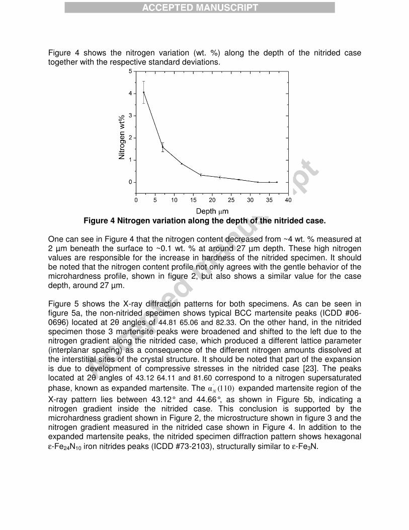
Figure 4 shows the nitrogen variation (wt. %) along the depth of the nitrided case together with the respective standard deviations.
Figure 4 Nitrogen variation along the depth of the nitrided case.
One can see in Figure 4 that the nitrogen content decreased from ~4 wt. % measured at 2 µm beneath the surface to ~0.1 wt. % at around 27 µm depth. These high nitrogen values are responsible for the increase in hardness of the nitrided specimen. It should be noted that the nitrogen content profile not only agrees with the gentle behavior of the microhardness profile, shown in figure 2, but also shows a similar value for the case depth, around 27 µm. Figure 5 shows the X-ray diffraction patterns for both specimens. As can be seen in figure 5a, the non-nitrided specimen shows typical BCC martensite peaks (ICDD #06-0696) located at 2θ angles of 44.81 65.06 and 82.33. On the other hand, in the nitrided specimen those 3 martensite peaks were broadened and shifted to the left due to the nitrogen gradient along the nitrided case, which produced a different lattice parameter (interplanar spacing) as a consequence of the different nitrogen amounts dissolved at the interstitial sites of the crystal structure. It should be noted that part of the expansion is due to development of compressive stresses in the nitrided case [23]. The peaks located at 2θ angles of 43.12 64.11 and 81.60 correspond to a nitrogen supersaturated phase, known as expanded martensite. The
´α (110)N
expanded martensite region of the X-ray pattern lies between 43.12° and 44.66°, as shown in Figure 5b, indicating a nitrogen gradient inside the nitrided case. This conclusion is supported by the microhardness gradient shown in Figure 2, the microstructure shown in figure 3 and the nitrogen gradient measured in the nitrided case shown in Figure 4. In addition to the expanded martensite peaks, the nitrided specimen diffraction pattern shows hexagonal ε-Fe24N10 iron nitrides peaks (ICDD #73-2103), structurally similar to ε-Fe3N.

Figure 5 X-ray diffraction patterns for nitrided and non-nitrided specimens.
3.2 Mass losses and Erosion Rates Cumulative mass losses variations as a function of exposure time are shown in figure 6. The scatter bars comprise one standard deviation. After 20 hours of testing, the non-nitrided specimen lost ~42 mg and the nitrided specimen lost ~1.5 mg. The nitrogen addition decreased 27 times the mass loss of the quenched and tempered AISI 410. The erosion rates were calculated from the slope of the straight line plotted from the fifth hour on, as shown in figure 6, accordingly, the erosion rates were 0.085 mg/h and 2.56 mg/h for nitrided and non-nitrided specimens, respectively.

Figure 6 Cumulative mass losses variations as a function of exposure time for nitrided and non-nitrided specimens. 3.3 Mechanical properties measured by nanoindentation Table II shows the hardness (H), the Young modulus (E), the H/E and H3/E2 ratios and the elastic recovery (We) for both specimens measured by nanoindentation tests. Table II Hardness (H), Young modulus (E), (H/E) and (H3/E2) ratios, maximum depth of penetration (hmax), residual depth after indentation (hf) and elastic recovery (We) for both specimens measured by nanoindentation tests.
Specimen E
(GPa) H
(GPa) H/E
H3/E2 (GPa)
hmax (nm)
hf (nm)
We (%)
Non-
nitrided 189.3 ±6.4
4.7 ±0.3
0.03 ±0.001
0.003 ±0.0004
234.3 ±5.9
197.7 ±6.6
15.7 ±0.9
Nitrided 191.5 ±7.4
13.7 ±0.75
0.07 ±0.003
0.07 ±0.008
148.4 ±3.8
81.4 ±4.2
45.1 ±1.6
The active screen plasma nitriding treatment had no effect in the Young modulus, the expanded martensite and the tempered martensite showing similar values of 191.5 ± 7.4 GPa and 189.3 ± 6.37 GPa, respectively. However, the formation of nitrogen expanded martensite increased the hardness almost 3 times, from 4.7 ± 0.24 GPa for the tempered martensite to 13.7 ± 0.75 for the expanded martensite. For comparison purposes, it has been reported that the expanded austenite hardness is 14 -18 GPa with Young modulus of 225 - 260 GPa [6]. The expanded martensite showed higher H/E and H3/E2 ratios indicating its capability to support high contact pressure, like those typically found in components submitted to cavitation. Greater H/E ratios are desirable

as they denote higher elastic deformation before failure by plastic deformation or cracking. Furthermore, the elastic recovery of expanded martensite was 45 % and only 15 % for tempered martensite, showing that plastic deformation (associated to final penetration after unloading hf) is the main deformation occurring in tempered martensite. These results suggest that the expanded martensite deforms mainly elastically during cavitation test. The impact energy released by the shock waves is elastically absorbed and then released to the medium, without significant plastic deformation or loosing considerable mass. Apparently, nitriding increased the yield strength of tempered martensite, leading to an increase of the elastic behavior of the expanded martensite nitrided case. The performance of the nitrided case is controlled by the resistance to elastoplastic deformation given by the expanded martensite. The increase in the cavitation erosion resistance is due to both, an increase in hardness and in the elastic response of the expanded martensite microstructure. The microstructure of the nitrided case is mostly homogenous and does not contain cracks, voids or other phases, which may act as nucleation sites for erosion. Apparently the ε-Fe3N iron nitrides precipitation is not harmful for the cavitation erosion resistance, most probably due to nanometric coherent precipitation. These results differ from those formerly obtained by the authors [5] after conventional low temperature plasma nitriding of AISI 410 stainless steel, in which ε-Fe3N and γ’-Fe4N iron nitrides precipitated near the surface of the expanded martensite case. In this work, iron nitrides could not be observed even at 8,000 times magnification in the SEM. In contrast the ε-Fe3N and γ´-Fe4N iron nitrides formed during conventional low temperature plasma nitriding could be easily observed at 2,500 times magnification. The active screen technic decreased the amount and the size of the ε-Fe3N precipitates and avoided γ´-Fe4N precipitation. 4 Wear Mechanisms 4.1 Non-nitrided specimen Figure 7 shows the evolution of the damage during the first hour of testing in non-nitrided specimen. Prior to the cavitation test, the surface was ground with emery papers up to ASTM 1,200 and then polished with 6, 3 and 1 µm diamond paste. It can be seen from figure 7b) that a significant change occurs at the surface within the first few minutes of testing: a slight relieve was created due to the formation of very small pits (1) and smooth grooves (2), indicating that the surface is undergoing plastic deformation. In figure the sequence 7c to 7f it may be seen that the grooves revealed prior austenitic grain boundaries (3), delineated due to material flow. In addition, martensite lath boundaries (4) were also revealed, as a consequence of plastic deformation. At this time, the mass loss was very low (~0.19 mg) and the main damage at the surface was plastic deformation.

a) Before Testing b) 15 minutes
c) 30 minutes d) 45 minutes
e) 60 minutes f) 60 minutes
Figure 7 Evolution of the damage during the first hour of testing in non-nitrided specimen, a) before testing b) 15 minutes of testing, c) 30 minutes of testing, d) 45 minutes of testing, e and f) 60 min. SEM images.
3
2
1
2
3
4
3
3 4
3
4

Plastic deformation increases and cavities (5) are formed along martensite lath boundaries and prior austenite grain boundaries. Furthermore, lath boundaries and grain boundaries act as barriers to material flow, causing an accumulation of strained-mass at these imperfections, creating protruding lips on the surface, shown in figure 8.
Figure 8 Cavities (5) and surface steps created due to mass accumulation at twins and grain boundaries after 120 minutes of testing. SEM images.
After 120 minutes of testing, the cumulative mass loss is around 0.30 mg indicating that some material was detaching from the protruding lips. Moreover, one can see that detachment of particles from these lips occurred mainly by a ductile mechanism, leaving very thin walls due to necking. In the interval between 150-180 minutes, the surface appearance strongly changed due to removal of the protruding lips, as shown in figure 9. Cavitation damage occurred by plastic deformation, possibly by fatigue and finally by ductile fracture mechanisms. The cumulative mass loss after 180 minutes of testing was ~0.75 mg.
150 minutes 180 minutes
Figure 9 Material detachment from the strained mass accumulated at protruding lips, due to a ductile fracture mechanism within 150 – 180 minutes of testing. SEM images.
5 5
1
5

a) 240 minutes
b) 360 minutes
c) 720 minutes d) 1200 minutes
Figure 10 Material detachment due to cleavage from ~180 minutes of testing until the end of the test, a) 240 minutes of testing, b) 360 minutes of testing, c) 720 minutes of testing and d) 1200 minutes of testing. SEM images.
6
6
6
6

However, from 180 minutes of testing on, it seems that the non-nitrided specimen changed from ductile to brittle behavior. Most probably, due to the presence of small cavities on the surface, the shock waves induced more complex states of stresses, changing the mechanical behavior of the deformed surface from ductile to brittle. Consequently, cracks are able to propagate rapidly by cleavage (6) without significant plastic deformation. The non-nitrided specimen showed this brittle response until the end of the test, as shown in figure 10. 4.2 Nitrided Specimen Figure 11 shows the nitrided specimen surface before and after 60 minutes of testing.
a) Before testing b) After 60 minutes of testing
Figure 11 Nitrided specimen surface, a) before the test and b) after 60 minutes of testing. SEM images. During the first 60 minutes of testing, some tiny pores (1) appeared inside some grains; but, generally speaking, the nitrided specimen surface did not show any significant change and most of the grains remained intact, supporting the fact that the expanded martensite elastically absorbed the shock-waves impact, without plastic deforming. After 105 minutes, the number of pores inside the grains was increased (2) and new pores were nucleated, not only in other grains (3) but also at grain boundaries (4), as can be seen in figure12. Furthermore, it can be seen in figure 12 that the damage inside the grain was nucleated at the martensite lath boundaries. The pores nucleation process, along the surface within grains and at grain boundaries, increased with the exposure time, wear particles were detached from the surface, as can be seen for 180 and 300 minutes of testing time in figures 13 and 14 respectively. Moreover, some former pores increased their size and depth, becoming craters (5), particularly those located at martensite laths. It can be inferred that the material removal is due to brittle fracture without plastic deformation.
1
1
1

Figure 12 New pores nucleation in other grains (3) and at grain boundaries (4) after 105 minutes of testing. SEM images.
Figure 13 Increase on pores nucleation within grains and at grain boundaries after 180 minutes of testing. SEM images.
2 3
3
2 4
4
5
5
3 4
3
4
5
5
3
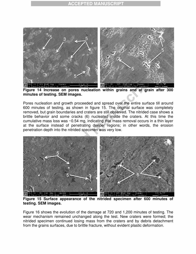
Figure 14 Increase on pores nucleation within grains and at grain after 300 minutes of testing. SEM images. Pores nucleation and growth proceeded and spread over the entire surface till around 600 minutes of testing, as shown in figure 15. The original surface was completely removed, but grain boundaries and craters are still observed. The nitrided case shows a brittle behavior and some cracks (6) nucleated inside the craters. At this time the cumulative mass loss was ~0.54 mg, indicating that mass removal occurs in a thin layer at the surface instead of penetrating deeper regions; in other words, the erosion penetration depth into the nitrided specimen was very low.
Figure 15 Surface appearance of the nitrided specimen after 600 minutes of testing. SEM images. Figure 16 shows the evolution of the damage at 720 and 1,200 minutes of testing. The wear mechanism remained unchanged along the test. New craters were formed; the nitrided specimen continued losing mass from the craters and by debris detachment from the grains surfaces, due to brittle fracture, without evident plastic deformation.
5 5
5
35
5
5
5
5 6

a ) After 720 minutes of testing
b) After 1200 minutes of testing
Figure 16 Nitrided specimen surface, a) after 720 minutes of testing and b) after 1200 minutes of testing. SEM images. 5 Conclusions Active Screen Plasma Nitriding produced a nitrided case formed by expanded nitrogen supersaturated martensite and hexagonal ε-Fe24N10 iron nitrides, with maximum hardness of 1275 HV measured on top of the nitrided surface. The microhardness measurements on the transverse section of the nitrided specimen and the nitrogen penetration depth measured by WDX indicated a nitrided case depth around 27-28 µm. After 20 hours of testing, the non-nitrided specimen lost ~42 mg and the nitrided specimen lost just ~1.5 mg. The Active Screen Plasma Nitrided nitrogen supersaturated expanded martensite decreased 27 times the mass loss compared to the quenched and

tempered AISI 410 stainless steel. The erosion rates were 0.085 mg/h and 2.56 mg/h for the nitrided and non-nitrided specimens, respectively. The elastic recovery was 15 % for tempered martensite and 45 % for expanded martensite. The expanded martensite showed higher H/E and H3/E2 ratios, indicating its capability to support higher contact pressures. The increase in cavitation erosion resistance is attributed to the increase in hardness and of the elastic response of the expanded martensite. The non-nitrided specimen changed from ductile to brittle behavior, therefore, two different modes of material detachment occurred. The first one characterized by high deformation, material flow, fatigue and material detachment, due to ductile rupture mechanisms. The second one, from around 180 minutes of testing on, may be described by the formation of craters by cleavage mechanisms, resulting in a greater erosion rate exhibited by the non-nitrided specimen in the later stages of cavitation. In the nitrided specimens, craters were formed at martensite lath boundaries and at prior austenite grain boundaries. The material removal mainly comes from the craters and from debris detachment from the grain surfaces due to brittle fracture, without plastic deformation. The wear mechanisms acting in the nitrided specimen remained unchanged along the test. Acknowledgments The authors acknowledge the supports of CNPq Processes n. 151653/2010-0 481918/2010-8 and 486104/2012-5, FAPESP, process n. 2012/50890-0 and COLCIENCIAS Process Number 497, Colombia. References
[1] D.H. Mesa et al. Improvement of the cavitation erosion resistance of UNS S31803 stainless steel by duplex treatment. Surface & Coatings Technology 205 (2010) 1552–1556.
[2] C.M. Garzón et al. Cavitation erosion resistance of a high temperature gas nitrided duplex stainless steel in substitute ocean water. Wear 259 (2005) 145–153.
[3] J.F. dos Santos et al. Improvement of the cavitation erosion resistance of an AISI 304L austenitic stainless steel by high temperature gas nitriding. Materials Science and Engineering A 382 (2004) 378–386.
[4] A.N. Allenstein et al. Improvement of the cavitation erosion resistance for low-temperature plasma nitrided Ca-6NM martensitic stainless steel. Wear 309 (2014) 159–165.
[5] L.A. Espitia et al. Cavitation erosion resistance of low temperature plasma nitrided martensitic stainless steel. Wear 301 (2013) 449–456.
[6] C. Tromas et al. Hardness and elastic modulus gradients in plasma-nitrided 316L polycrystalline stainless steel investigated by nanoindentation tomography, Acta Materialia 60 (2012) 1965–1973.
[7] E. Menthe et al. Improvement of the mechanical properties of austenitic stainless steel after plasma nitriding, Surface and Coatings Technology 133 -1134, p 259 – 263, 2000.
[8] J.C. Stinville et al. Anisotropy changes in hardness and indentation modulus induced by plasma nitriding of 316L polycrystalline stainless steel Scripta Materialia 64 (2011) 37–40.
[9] C. J. Heathcock and B. E. Protheroe. Cavitation erosion of stainless steels. Wear 81 (1982) 311 – 327.
[10] G. Bregliozzi et al. Cavitation wear behavior of austenitic stainless steels with different grain sizes. Wear 258 (2005) 503–510.
[11] B.S. Mann. Boronizing of cast martensitic chromium nickel stainless steel and its abrasion and cavitation-erosion behavior. Wear 208 (1997) 125–131.
[12] A. Thiruvengadam, S. Waring, Mechanical properties of metals and their cavitation damage resistance, Technical Report 233-5, Hydronautics, Incorporated (1964) 1–47.
[13] A. Karimi and J.L. Martin. Cavitation erosion of materials. International Material Reviews. Vol 31 No1.
[14] Raghuvir Singh, S.K. Tiwari, and Suman K. Mishra. Cavitation Erosion in Hydraulic Turbine Components and Mitigation by Coatings: Current Status and Future Needs. Journal of Materials Engineering and Performance. Volume 21 (7) July 2012—1539.
[15] C.X.Li, T. Bell and H. Dong. A study of active screen plasma nitriding. Surface Engineering 2002 Vol 18 No 3.
[16] A. Toro, A. P. Tschiptschin. Chemical characterization of a high nitrogen stainless steel by optimized electron probe microanalysis Scripta Materialia 63 (2010) 803–806.
[17] W.C. Oliver; G.M. Pharr. A new improved technique for determining hardness and modulus using load and sensitive indentation experiments, Journal of Materials Research, v7, p 1564-1582,1992.
[18] AMERICAN SOCIETY FOR TESTING AND MATERIALS ASTM G32. Standard test method for cavitation erosion using vibratory apparatus. Annual book of ASTM standards 1998.
[19] DIN 50190-3. Hardness depth of heat-treated parts; determination of the effective depth of hardening after nitriding. STANDARD by Deutsches Institut Fur Normung E.V. (German National Standard), 03/01/1979.
[20] Carlos E. Pinedo, Waldemar A. Monteiro. On the kinetics of plasma nitriding a martensitic stainless steel type AISI 420. Surface and Coatings Technology 179 (2004) 119–123.

[21] S.K. Kim et al Characteristics of martensitic stainless steel nitrided in a low-pressure RF plasma. Surface and Coatings Technology 163 –164 (2003) 380–385.
[22] T. Christiansen; M.A.J. Somers. Nitrogen diffusion and nitrogen depth profiles in expanded austenite: experimental assessment, numerical simulation and role of stress. Materials Science and Technology v24 p.159-167, 2008.
[23] T. Christiansen, M.A.J. Somers, Stress and composition of carbon stabilized expanded austenite on stainless steel, Metallurgical and Materials Transaction A 40A (2009) 1791–1798.