cavern/vault disposal concepts and thermal...
TRANSCRIPT

Cavern/Vault DisposalConcepts and Thermal Calculations for Direct Disposal of 37-PWR Size DPCs
Prepared for
U.S. Department of Energy
Used Fuel Disposition Campaign
Teklu Hadgu, Dan Clayton and Ernest Hardin
Sandia National Laboratories
February 2015FCRD-UFD-2015-000715
SAND2015-1453R
February 2015 ii
Revision History
Version Description
FCRD-UFD-2015-000715 Initial Release (SAND2015-*****).
UNCLASSIFIED UNLIMITED RELEASE
Sandia National Laboratories is a multi-program laboratory managed and operated by Sandia Corporation, a wholly owned subsidiary of Lockheed Martin Corporation, for the U.S. Department of Energy National Nuclear Security Administration under contract DE-AC04-94AL85000.
DISCLAIMER
This information was prepared as an account of work sponsored by an agency of the U.S. Government. Neither the U.S. Government nor any
agency thereof, nor any of their employees, makes any warranty, expressed or implied, or assumes any legal liability or responsibility for
the accuracy, completeness, or usefulness, of any information, apparatus, product, or process disclosed, or represents that its use would not infringe
privately owned rights. References herein to any specific commercial product, process, or service by trade name, trade mark, manufacturer, or
otherwise, does not necessarily constitute or imply its endorsement, recommendation, or favoring by the U.S. Government or any agency thereof. The views and opinions of authors expressed herein do not
necessarily state or reflect those of the U.S. Government or any agency thereof.
February 2015 3
Table of ContentsIntroduction...............................................................................................................................7
1. Thermal Analyses of 37-PWR Size DPC Direct Disposal Concepts....................................7
1.1 Sedimentary Backfilled, Open, In-Drift Emplacement with 37-PWR Size DPCs ...............7
1.2 Hard-Rock Open, In-Drift Emplacement with 37-PWR Size DPCs ...................................9
1.2.1 Hard-Rock Unbackfilled, Open, Unsaturated, In-Drift Concept..............................9
1.2.2 Hard-Rock Backfilled, Open, In-Drift Concept ....................................................11
1.3 Thermal Analyses of Salt Disposal Concept using Finite Element Solution....................13
1.4 Parametric Study of Spacings for Sedimentary Open Concepts, with 37-PWR Size Packages........................................................................................................................17
2. Cavern-Retrievable Storage and Disposal .........................................................................18
2.1 Thermal Analysis of Vertical Floor Vaults ......................................................................18
3. Summary .............................................................................................................................24
References................................................................................................................................24
February 2015 4
List of Figures
Figure 1-1. Temperature histories (drift wall and waste package surface) for various SNF burnup levels in 37-PWR sized packages, in a sedimentary backfilled repository with spacings shown, for: (top) 50-year decay storage and 100-year ventilation, and (bottom) 100-year decay storage and 200-year ventilation. ............................................................................................................. 8
Figure 1-2. Temperature histories (drift wall and waste package surface) for various SNF burnup levels in 37-PWR sized packages, in a hard rock open (unbackfilled) repository with spacings shown, for: (top) 50-year decay storage and 100-year ventilation, and (bottom) 100-year decay storage and 200-year ventilation.............................................................................................. 10
Figure 1-3. Temperature histories (drift wall and waste package surface) for various SNF burnup levels in 37-PWR sized packages, in a hard rock open (backfilled) repository with spacings shown, for: (top) 50-year decay storage and 100-year ventilation, and (bottom) 100-year decay storage and 200-year ventilation. ........................................................................................................... 12
Figure 1-4. Temperature histories for 37-PWR size packages, for the salt concept, with in-drift emplacement and 30-m spacing, and fully coupled thermal-mechanical solution: 40 GW-d/MT, 50 years out-of-reactor.................................. 14
Figure 1-5 Temperature histories for 37-PWR size packages, for the salt concept, with in-drift emplacement and 30-m spacing: 40 GW-d/MT, 50 years out-of-reactor, run with fully coupled thermal-mechanical solution with floor cavity. .................................................................................................................. 14
Figure 1-6 Temperature histories for 37-PWR size packages, for the salt concept, with in-drift emplacement and 30-m spacing, and fully coupled thermal-mechanical solution. 40 GW-d/MT, 80 years out-of-reactor.................................. 15
Figure 1-7. Temperature histories for 37-PWR size packages, for the salt concept, with in-drift emplacement and 30-m spacing, and fully coupled thermal-mechanical solution. 60 GW-d/MT, 100 years out of reactor. ............................... 15
Figure 1-8. Temperature histories for 37-PWR size packages, for the salt concept, with in-drift emplacement and 30-m spacing. 60 GW-d/MT, 100 years out of reactor, run with fully coupled thermal-mechanical solution with floor cavity. .................................................................................................................. 16
Figure 1-9. Temperature histories for 37-PWR size packages, for the salt concept, with in-drift emplacement and 30-m spacing, and fully coupled thermal-mechanical solution: 60 GW-d/MT, 125 years Out of Reactor. ............................. 16
Figure 1-10. Peak temperature vs. package spacing for the drift wall and 1 m into the wall, for the sedimentary concept, comparing 70 and 90-m drift spacings (37-PWR size packages, 60 GW-d/MT burnup).................................................... 17
Figure 2-1. Conceptual diagram for storage/disposal of DPCs in drifts with vertical floor vaults, cross-sectional view. ......................................................................... 20
Figure 2-2. Temperature histories (drift wall and waste package surface) at different ventilation times for SNF burnup level of 20 GWd/MT in 32-PWR sized DPCs, in a hard rock open (backfilled) repository. ................................................ 21
February 2015 5
Figure 2-3. Temperature histories (drift wall and waste package surface) at different ventilation times for SNF burnup level of 40 GWd/MT in 32-PWR sized DPCs, in a hard rock open (backfilled) repository. ................................................ 21
Figure 2-4. Temperature histories (drift wall and waste package surface) at different ventilation times for SNF burnup level of 60 GWd/MT in 32-PWR sized DPCs, in a hard rock open (backfilled) repository. ................................................ 22
Figure 2-5. Peak temperature vs. buffer thickness, for the emplacement of DPCs in vertical borehole concept, in hard rock host media, comparing various buffer thermal conductivities (32-PWR size packages, 20, 40 and 60 GW-d/MT burnups, fuel age100 years at closure)......................................................... 22
Figure 2-6. Peak temperature vs. buffer thickness, for emplacement of DPCs in vertical vault concept, comparing various buffer thermal conductivities (32-PWR size packages, 20, 40 and 60 GW-d/MT burnups, fuel age150 years at closure). ............................................................................................................... 23
Figure 2-7. Peak temperature vs. buffer thickness, for the emplacement of DPCs in vertical borehole concept, in hard rock host media, comparing various buffer thermal conductivities (32-PWR size packages, 20, 40 and 60 GW-d/MT burnups, fuel age 200 years at closure)........................................................ 23
February 2015 6
ACRONYMS
BWR Boiling Water Reactor
DOE U.S. Department of EnergyDPC Dual-Purpose Canister
EBS Engineered Barrier System
GW Gigawatt
Hi-Storm Trade Name for Vertical Dry Storage Systems (Holtec International)HLW High-Level Waste
KBS-3 Swedish Reference Disposal ConceptKth Thermal Conductivity
MT Metric Tons
NUHOMS Trade Name for Vault –Type Dry Storage System (Transnuclear)
PWR Pressurized Water Reactor
R&D Research and Development
SNF Spent Nuclear FuelSNL Sandia National Laboratories
UFD Used Fuel Disposition
February 2015 7
CAVERN/VAULT DISPOSAL CONCEPTS AND THERMAL CALCULATIONS FOR DIRECT DISPOSAL OF 37-PWR SIZE DUAL-
PURPOSE CANISTERS
Introduction
This report provides two sets of calculations not presented in previous reports on the technical feasibility of spent nuclear fuel (SNF) disposal directly in dual-purpose canisters (DPCs): 1) thermal calculations for reference disposal concepts using larger 37-PWR size DPC-based waste packages, and 2) analysis and thermal calculations for underground vault-type storage and eventual disposal of DPCs. The reader is referred to the earlier reports (Hardin et al. 2011, 2012, 2013; Hardin and Voegele 2013) for contextual information on DPC direct disposal alternatives.
1. Thermal Analyses of 37-PWR Size DPC Direct Disposal Concepts
This analysis is an extension of previous work (Hardin et. al., 2011, 2012, 2013; Hardin and Voegele 2013). The focus of this work is the higher heat output of larger DPCs, represented by those containing 37 PWR assemblies (or BWR equivalent). A parametric study to assess the sensitivity of peak near-field temperature is also presented. Thermal analysis is conducted using the Mathcad-based semi-analytical method (Greenberg et al. 2012), with the exception of salt disposal for which the finite element method was used.
1.1 Sedimentary Backfilled, Open, In-Drift Emplacement with 37-PWR Size DPCs
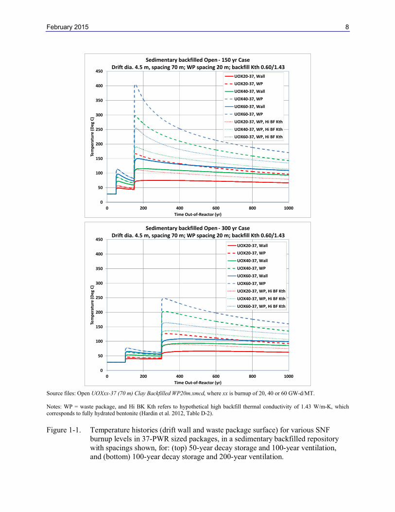
The thermal analysis described in Hardin et al. (2013, Section 4.5) was extended to 37-PWR waste packages. The waste package size is assumed to be the same as for 32-PWR (the diameter of larger size DPCs is only a few percent greater, and length is the same). The results are shown in Figure 1-1 for two storage and ventilation time periods. As a result of the higher heat output, temperatures at both the drift wall and backfill (near waste package surface) are higher. Backfill temperatures remain higher than 100°C for hundreds of years, for all burnup levels. This applies to the cases for 150 years out-of-reactor (top) and 300 years out-of-reactor (bottom). Peak backfill temperatures are also higher. For the 40 and 60 GW-d/MT burnup levels, peak backfill temperatures are greater than 200°C for hundreds of years after closure (bottom). The use of backfill material with higher thermal conductivity would significantly reduce the peak backfill temperatures. For example, for the case of closure 150 years out-of-reactor, the peak backfill temperature for 20 GW-d/MT burnup is only slightly more than 100°C. For the case with 300 years out-of-reactor, the peak backfill temperature for 60 GW-d/MT burnup is much lower than 200°C. Thus, use of backfill materials with higher thermal conductivity and with tolerance for temperature greater than 100°C would advance disposal of DPCs in sedimentary host rock.
February 2015 8
Source files: Open UOXxx-37 (70 m) Clay Backfilled WP20m.xmcd, where xx is burnup of 20, 40 or 60 GW-d/MT.
Notes: WP = waste package, and Hi BK Kth refers to hypothetical high backfill thermal conductivity of 1.43 W/m-K, which corresponds to fully hydrated bentonite (Hardin et al. 2012, Table D-2).
Figure 1-1. Temperature histories (drift wall and waste package surface) for various SNF burnup levels in 37-PWR sized packages, in a sedimentary backfilled repositorywith spacings shown, for: (top) 50-year decay storage and 100-year ventilation, and (bottom) 100-year decay storage and 200-year ventilation.
0
50
100
150
200
250
300
350
400
450
0 200 400 600 800 1000
Tem
pe
ratu
re (
De
g C
)
Time Out-of-Reactor (yr)
Sedimentary backfilled Open - 150 yr Case Drift dia. 4.5 m, spacing 70 m; WP spacing 20 m; backfill Kth 0.60/1.43
UOX20-37, Wall
UOX20-37, WP
UOX40-37, Wall
UOX40-37, WP
UOX60-37, Wall
UOX60-37, WP
UOX20-37, WP, Hi BF Kth
UOX40-37, WP, Hi BF Kth
UOX60-37, WP, Hi BF Kth
0
50
100
150
200
250
300
350
400
450
0 200 400 600 800 1000
Tem
pe
ratu
re (
De
g C
)
Time Out-of-Reactor (yr)
Sedimentary backfilled Open - 300 yr Case Drift dia. 4.5 m, spacing 70 m; WP spacing 20 m; backfill Kth 0.60/1.43
UOX20-37, Wall
UOX20-37, WP
UOX40-37, Wall
UOX40-37, WP
UOX60-37, Wall
UOX60-37, WP
UOX20-37, WP, Hi BF Kth
UOX40-37, WP, Hi BF Kth
UOX60-37, WP, Hi BF Kth
February 2015 9
1.2 Hard-Rock Open, In-Drift Emplacement with 37-PWR Size DPCs
Hard rock open in-drift emplacement concept for disposal of SNF DPCs is described in Hardin et al. (2013, Section 4.6). The advantages of this concept are that the formation has the potential to provide opening stability, and the host rock tolerates higher temperatures. In this concept, thermal conditions can be optimized by varying drift and waste package spacings. In addition, use of ventilation would further reduce heat in the repository. Sections 1.2.1 and 1.2.2 describe thermal analysis for the unbackfilled and backfilled “open” concepts, respectively.
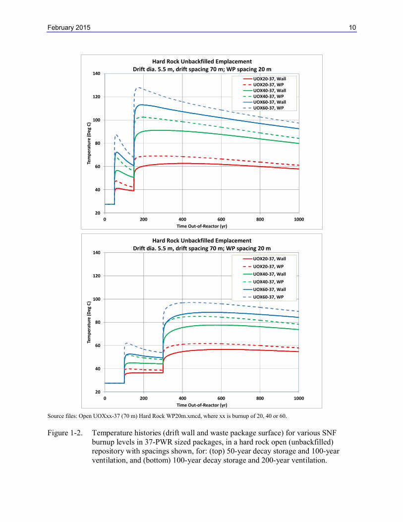
1.2.1 Hard-Rock Unbackfilled, Open, Unsaturated, In-Drift Concept
The thermal analysis described in Hardin et al. (2013, Section 4.6.1) was extended to 37-PWR size waste packages. The results (Figure 1-2) show that with higher heat output, both the drift wall and waste package temperatures are generally higher than for 32-PWR packages. However, peak waste package temperatures are similar even for higher burnup levels. As stated in Hardin et al. (2013, Section 4.6.1), hard rock host rock could be suitable for disposal with temperatures up to 200°C. A drift wall temperature target of 200°C would be easily met by ventilating for 100 years in addition to 50 years of surface decay storage (top). This suggests that the storage and ventilation periods could be further reduced and meet the target temperature for all burnup levels. The thermal calculation is based on host rock thermal conductivity of 2.5 W/m-K.
February 2015 10
Source files: Open UOXxx-37 (70 m) Hard Rock WP20m.xmcd, where xx is burnup of 20, 40 or 60.
Figure 1-2. Temperature histories (drift wall and waste package surface) for various SNF burnup levels in 37-PWR sized packages, in a hard rock open (unbackfilled) repository with spacings shown, for: (top) 50-year decay storage and 100-year ventilation, and (bottom) 100-year decay storage and 200-year ventilation.
20
40
60
80
100
120
140
0 200 400 600 800 1000
Tem
pe
ratu
re (D
eg
C)
Time Out-of-Reactor (yr)
Hard Rock Unbackfilled Emplacement Drift dia. 5.5 m, drift spacing 70 m; WP spacing 20 m
UOX20-37, WallUOX20-37, WPUOX40-37, WallUOX40-37, WPUOX60-37, WallUOX60-37, WP
20
40
60
80
100
120
140
0 200 400 600 800 1000
Tem
per
atu
re (
Deg
C)
Time Out-of-Reactor (yr)
Hard Rock Unbackfilled Emplacement Drift dia. 5.5 m, drift spacing 70 m; WP spacing 20 m
UOX20-37, Wall
UOX20-37, WP
UOX40-37, Wall
UOX40-37, WP
UOX60-37, Wall
UOX60-37, WP
February 2015 11
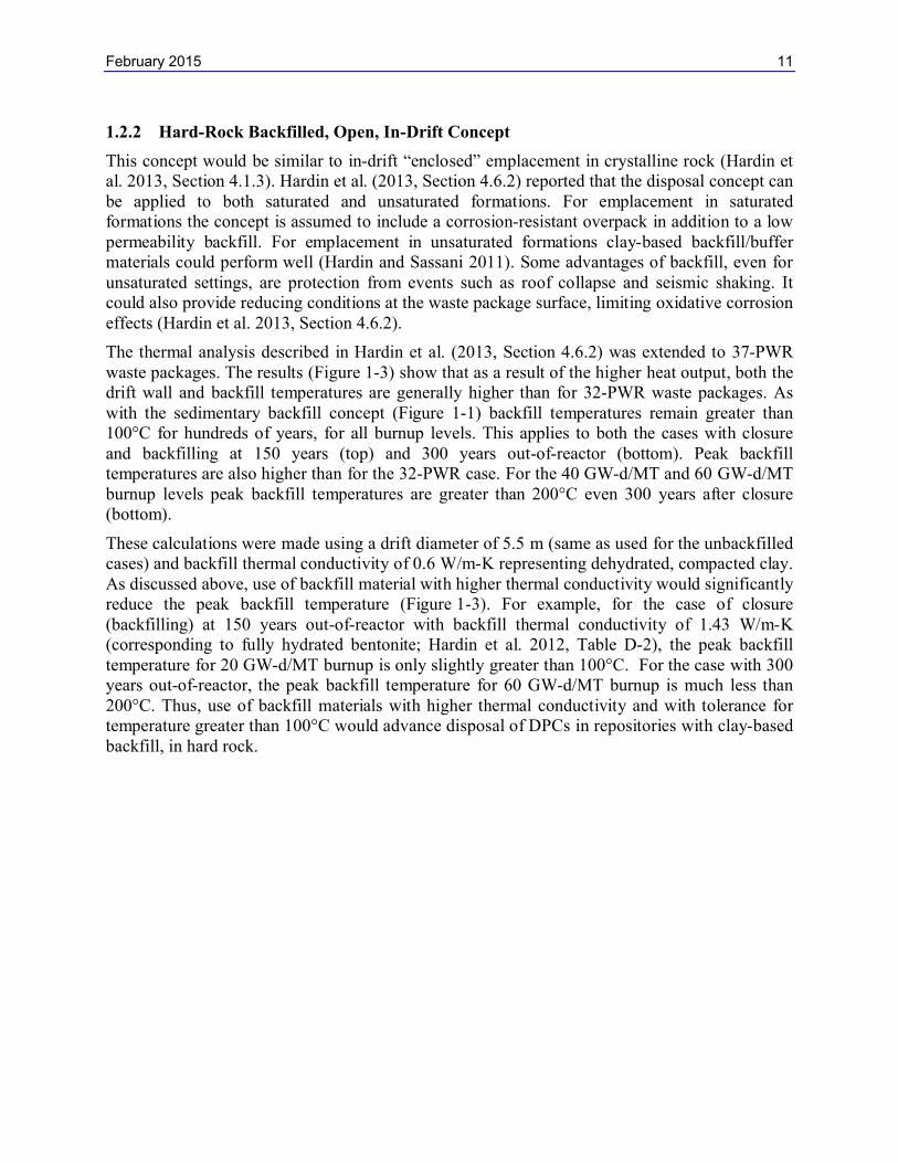
1.2.2 Hard-Rock Backfilled, Open, In-Drift Concept
This concept would be similar to in-drift “enclosed” emplacement in crystalline rock (Hardin et al. 2013, Section 4.1.3). Hardin et al. (2013, Section 4.6.2) reported that the disposal concept can be applied to both saturated and unsaturated formations. For emplacement in saturated formations the concept is assumed to include a corrosion-resistant overpack in addition to a low permeability backfill. For emplacement in unsaturated formations clay-based backfill/buffer materials could perform well (Hardin and Sassani 2011). Some advantages of backfill, even for unsaturated settings, are protection from events such as roof collapse and seismic shaking. It could also provide reducing conditions at the waste package surface, limiting oxidative corrosion effects (Hardin et al. 2013, Section 4.6.2).
The thermal analysis described in Hardin et al. (2013, Section 4.6.2) was extended to 37-PWR waste packages. The results (Figure 1-3) show that as a result of the higher heat output, both the drift wall and backfill temperatures are generally higher than for 32-PWR waste packages. As with the sedimentary backfill concept (Figure 1-1) backfill temperatures remain greater than 100°C for hundreds of years, for all burnup levels. This applies to both the cases with closure and backfilling at 150 years (top) and 300 years out-of-reactor (bottom). Peak backfill temperatures are also higher than for the 32-PWR case. For the 40 GW-d/MT and 60 GW-d/MT burnup levels peak backfill temperatures are greater than 200°C even 300 years after closure (bottom).
These calculations were made using a drift diameter of 5.5 m (same as used for the unbackfilled cases) and backfill thermal conductivity of 0.6 W/m-K representing dehydrated, compacted clay. As discussed above, use of backfill material with higher thermal conductivity would significantly reduce the peak backfill temperature (Figure 1-3). For example, for the case of closure (backfilling) at 150 years out-of-reactor with backfill thermal conductivity of 1.43 W/m-K(corresponding to fully hydrated bentonite; Hardin et al. 2012, Table D-2), the peak backfill temperature for 20 GW-d/MT burnup is only slightly greater than 100°C. For the case with 300 years out-of-reactor, the peak backfill temperature for 60 GW-d/MT burnup is much less than 200°C. Thus, use of backfill materials with higher thermal conductivity and with tolerance for temperature greater than 100°C would advance disposal of DPCs in repositories with clay-based backfill, in hard rock.

February 2015 12
Source files: Open UOXxx-37 (70 m) Hard Rock Backfilled WP20m.xmcd, where xx is burnup of 20, 40 or 60.
Notes: WP = waste package, and Hi BK Kth refers to hypothetical high backfill thermal conductivity of 1.43 W/m-K, which corresponds to fully hydrated bentonite (Hardin et al. 2012, Table D-2)..
Figure 1-3. Temperature histories (drift wall and waste package surface) for various SNF burnup levels in 37-PWR sized packages, in a hard rock open (backfilled) repository with spacings shown, for: (top) 50-year decay storage and 100-year ventilation, and (bottom) 100-year decay storage and 200-year ventilation.
February 2015 13
1.3 Thermal Analyses of Salt Disposal Concept using Finite Element Solution
Thermal analysis of the salt disposal concept presented here was done using the finite element method using Sandia National Laboratories’ Sierra suite of codes (Clayton et al. 2013). Creep models for intact and crushed salt were used, with thermal-mechanical coupling and temperature-dependent thermal conductivity. The simulation method allows for mechanical consolidation of the crushed salt backfill which affects its thermal properties. In addition the method allows variations in DPC emplacement geometry.
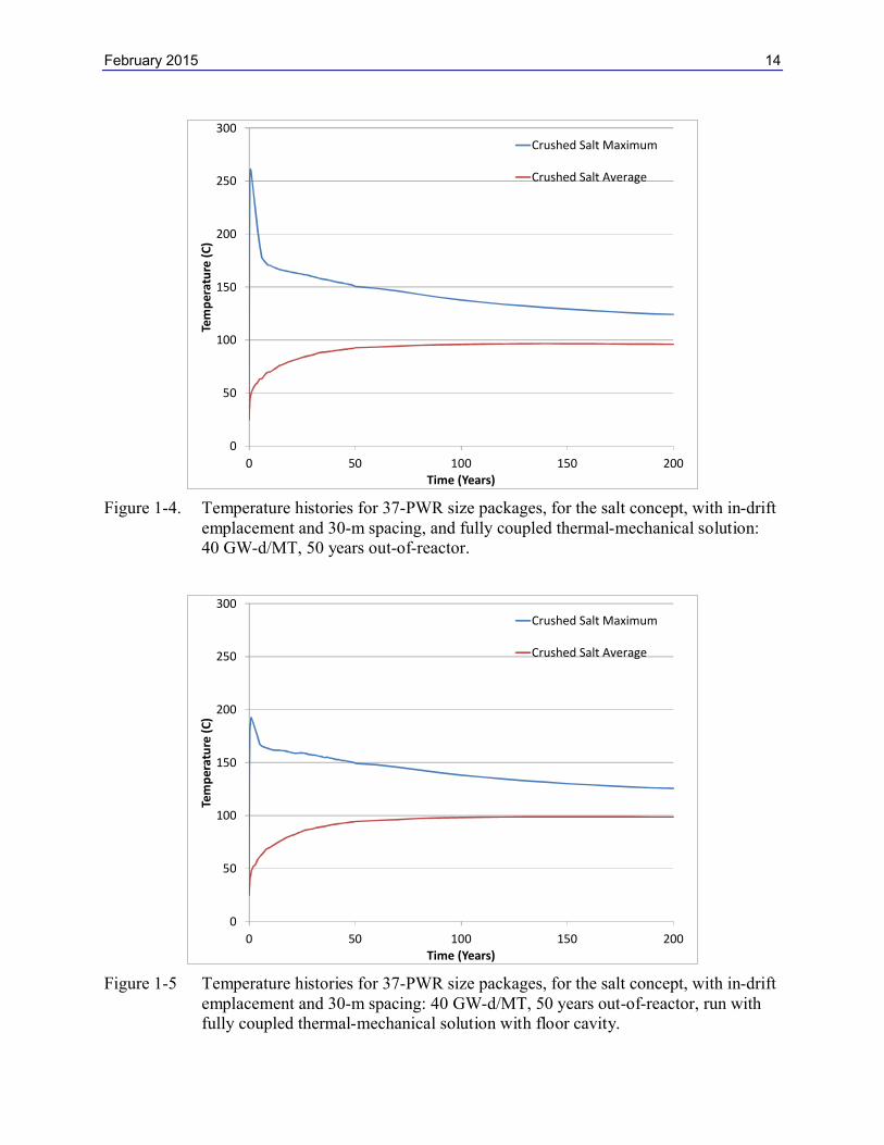
The finite-element based thermal analysis described in Hardin et al. (2013, Section 5.2) was extended to 37-PWR waste packages (Figures 1-4 through 1-9). The analysis is for the in-drift emplacement mode which is well suited for disposal of large, heavy packages. Waste package size was assumed to be the same as for 32-PWR DPC-based packages, and only thermal output was updated. The simulations represented waste package emplacement directly on the drift floor, and also in semi-cylindrical floor cavities. The fuel age at emplacement was varied in order tobetter meet a target peak salt temperature limit of 200 °C.
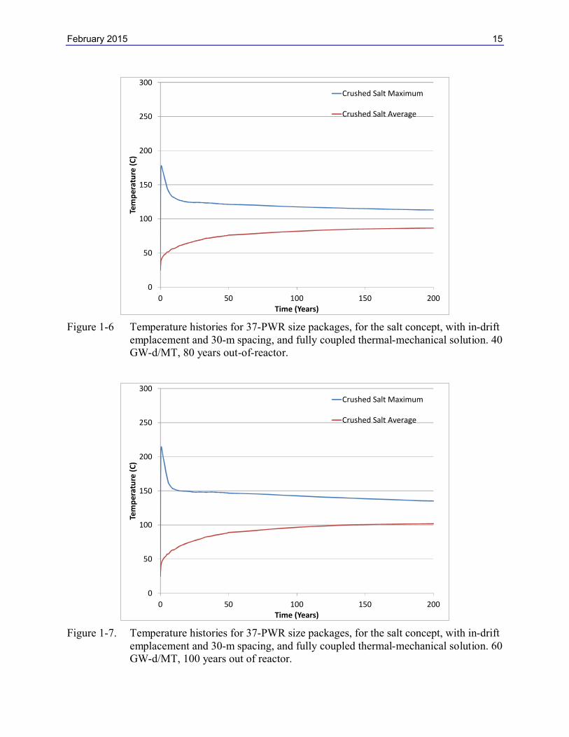
Figure 1-4 presents temperature histories for 37-PWR size waste packages with 40 GW-d/MT burnup SNF, emplaced at 50 years out-of-reactor. The calculation uses a fully coupled thermal-mechanical solution to represent in-drift emplacement with 30 m waste package spacing, and no floor cavities (Clayton et al. 2012). The peak temperature for the crushed salt maximum porosity case is significantly higher than the target limit of 200°C. Figure 1-5 shows results for emplacement using floor cavities, with everything else being the same as for Figure 1-4. In this case, the peak temperature is below the target temperature limit as a result of improved heat transfer. Figure 1-6 shows temperature results for emplacement after 80 years decay storage, with everything the same as in Figure 1-4.
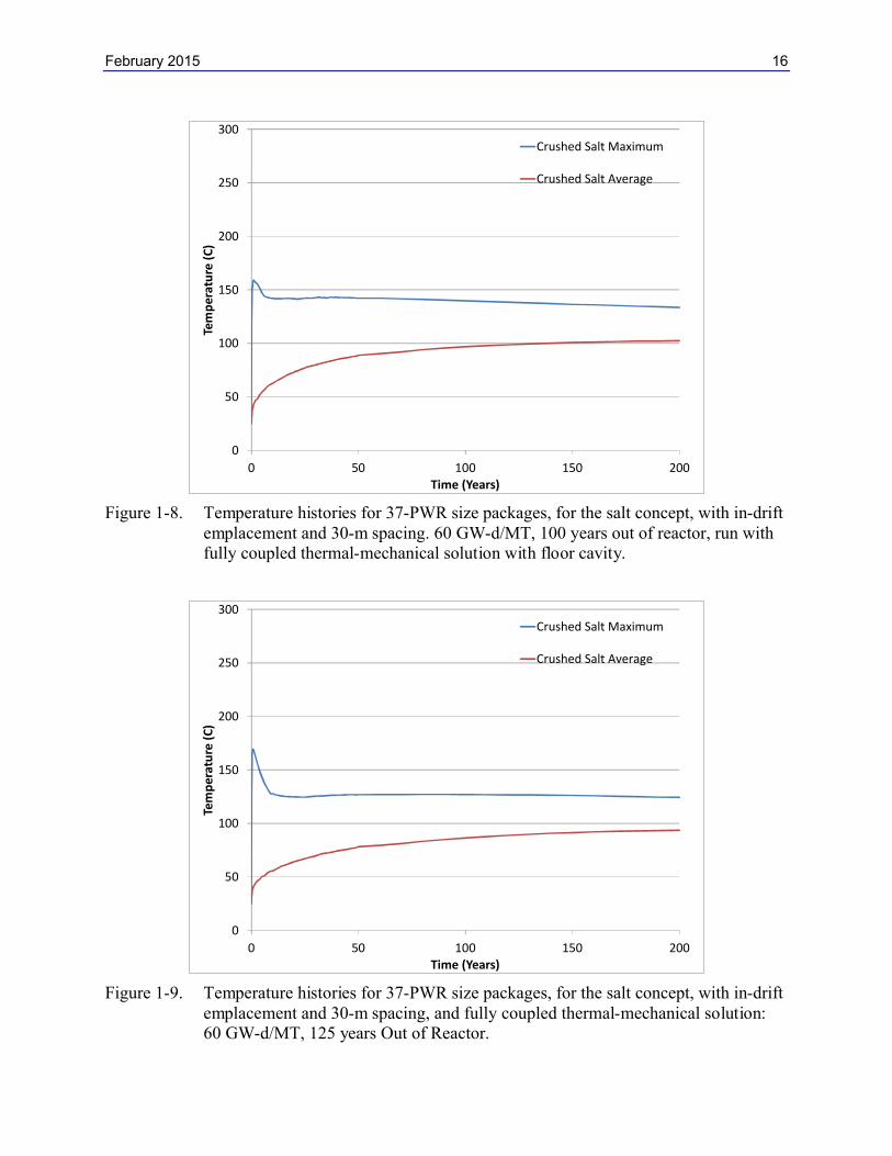
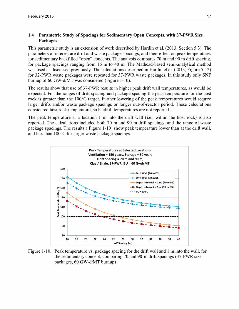
Figure 1-7 presents temperature histories for 37-PWR size waste packages containing 60 GW-d/MT burnup fuel with 100 years of decay storage (out-of-reactor). The calculation represents in-drift emplacement with 30 m waste package spacing and no floor cavities. The peak salt temperature is slightly greater than 200 °C. The peak salt temperature is greater than for 32-PWR size packages (compare with Figure 5-5 of Hardin et al. 2013). Lowering the peak salt temperature to 200C would require aging the fuel more than 100 years or use of floor cavities (which improves coupling to intact-salt, with much greater thermal conductivity than crushed salt backfill). These two approaches are presented in Figures 1-8 and 1-9. Figure 1-8 shows results with placement in floor cavities, with everything else the same as Figure 1-7. Figure 1-9shows results with 125 years out-of-reactor, everything else being the same as in Figure 1-7. The effect of floor cavities is similar to longer decay storage. Enhancements like floor cavities or forced ventilation (Hardin et al. 2012, Appendix C) are directly comparable to longer decay storage.
February 2015 14
Figure 1-4. Temperature histories for 37-PWR size packages, for the salt concept, with in-drift emplacement and 30-m spacing, and fully coupled thermal-mechanical solution: 40 GW-d/MT, 50 years out-of-reactor.
Figure 1-5 Temperature histories for 37-PWR size packages, for the salt concept, with in-drift emplacement and 30-m spacing: 40 GW-d/MT, 50 years out-of-reactor, run with fully coupled thermal-mechanical solution with floor cavity.
0
50
100
150
200
250
300
0 50 100 150 200
Tem
per
atu
re (
C)
Time (Years)
Crushed Salt Maximum
Crushed Salt Average
0
50
100
150
200
250
300
0 50 100 150 200
Tem
per
atu
re (
C)
Time (Years)
Crushed Salt Maximum
Crushed Salt Average
February 2015 15
Figure 1-6 Temperature histories for 37-PWR size packages, for the salt concept, with in-drift emplacement and 30-m spacing, and fully coupled thermal-mechanical solution. 40 GW-d/MT, 80 years out-of-reactor.
Figure 1-7. Temperature histories for 37-PWR size packages, for the salt concept, with in-drift emplacement and 30-m spacing, and fully coupled thermal-mechanical solution. 60 GW-d/MT, 100 years out of reactor.
0
50
100
150
200
250
300
0 50 100 150 200
Tem
per
atu
re (
C)
Time (Years)
Crushed Salt Maximum
Crushed Salt Average
0
50
100
150
200
250
300
0 50 100 150 200
Tem
per
atu
re (
C)
Time (Years)
Crushed Salt Maximum
Crushed Salt Average
February 2015 16
Figure 1-8. Temperature histories for 37-PWR size packages, for the salt concept, with in-drift emplacement and 30-m spacing. 60 GW-d/MT, 100 years out of reactor, run with fully coupled thermal-mechanical solution with floor cavity.
Figure 1-9. Temperature histories for 37-PWR size packages, for the salt concept, with in-drift emplacement and 30-m spacing, and fully coupled thermal-mechanical solution:60 GW-d/MT, 125 years Out of Reactor.
0
50
100
150
200
250
300
0 50 100 150 200
Tem
per
atu
re (
C)
Time (Years)
Crushed Salt Maximum
Crushed Salt Average
0
50
100
150
200
250
300
0 50 100 150 200
Tem
per
atu
re (
C)
Time (Years)
Crushed Salt Maximum
Crushed Salt Average
February 2015 17
1.4 Parametric Study of Spacings for Sedimentary Open Concepts, with 37-PWR Size Packages
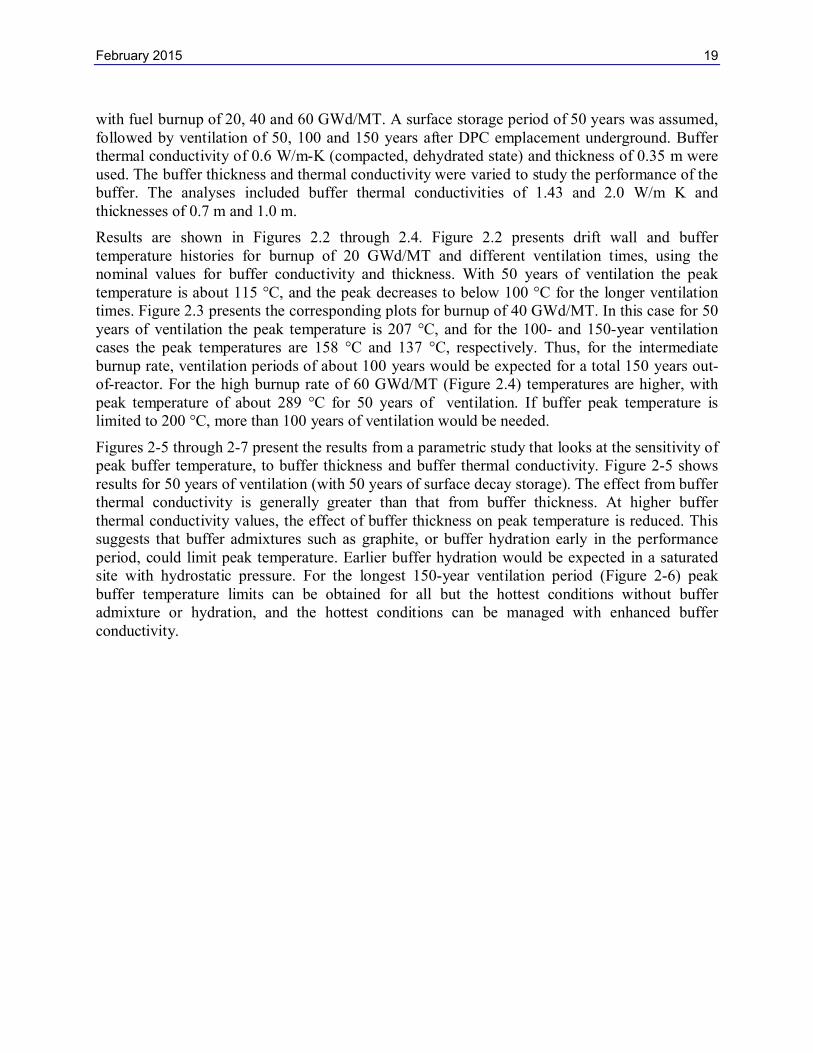
This parametric study is an extension of work described by Hardin et al. (2013, Section 5.3). The parameters of interest are drift and waste package spacings, and their effect on peak temperatures for sedimentary backfilled “open” concepts. The analysis compares 70 m and 90 m drift spacing, for package spacings ranging from 16 m to 40 m. The Mathcad-based semi-analytical method was used as discussed previously. The calculations described in Hardin et al. (2013, Figure 5-12) for 32-PWR waste packages were repeated for 37-PWR waste packages. In this study only SNF burnup of 60 GW-d/MT was considered (Figure 1-10).
The results show that use of 37-PWR results in higher peak drift wall temperatures, as would be expected. For the ranges of drift spacing and package spacing the peak temperature for the host rock is greater than the 100°C target. Further lowering of the peak temperatures would require larger drifts and/or waste package spacings or longer out-of-reactor period. These calculations considered host rock temperature, so backfill temperatures are not reported.
The peak temperature at a location 1 m into the drift wall (i.e., within the host rock) is also reported. The calculations included both 70 m and 90 m drift spacings, and the range of waste package spacings. The results ( Figure 1-10) show peak temperature lower than at the drift wall, and less than 100°C for larger waste package spacings.
Figure 1-10. Peak temperature vs. package spacing for the drift wall and 1 m into the wall, for the sedimentary concept, comparing 70 and 90-m drift spacings (37-PWR size packages, 60 GW-d/MT burnup)
80
90
100
110
120
130
140
150
16 18 20 22 24 26 28 30 32 34 36 38 40
Pea
k Te
mp
erat
ure
(Deg
C)
WP Spacing (m)
Peak Temperatures at Selected LocationsVentilation = 150 years, Storage = 50 years
Drift Spacing = 70 m and 90 m, Clay / Shale, 37-PWR, BU = 60 Gwd/MT
Drift Wall (70 m DS)
Drift Wall (90 m DS)
Depth into rock = 1 m, (70 m DS)
Depth into rock = 1m, (90 m DS)
TC = 100 C

February 2015 18
2. Cavern-Retrievable Storage and Disposal
Vault concepts for DPC direct disposal were discussed originally by Hardin et al. (2013). These vaults would be underground, shielded, ventilated systems that would maintain DPCs in storage for at least 100 years. For disposal, the interstices within the vaults, and the access drifts, ramps, and shafts would be backfilled with low-permeability clay-based material.
The previous study identified two general concepts: purpose-built vaults that would accept DPCs, and galleries that would accept DPCs in the same storage overpacks used for dry storage at the surface. The latter idea is similar to earlier concepts (McKinley et al. 2001, 2006 and 2008) for disposition of HLW in much smaller canisters. Existing vertical storage overpacks or casks, and horizontal vaults, typically are fabricated on-site using reinforced concrete. Although some storage overpacks can be moved within fuel storage facilities, they are not designed to be moved large distances. Hence, the former, purpose-built vault concept is more viable for DPCs that are stored at many locations in the U.S. and will continue to be deployed in the foreseeable future.
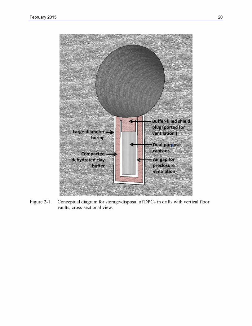
Vaults would be similar to surface storage concepts such as the NUHOMS® systems (horizontal) or the subterranean Hi-Storm 100 system (vertical), but with added features (e.g., low-permeability buffer) for waste isolation after closure (Hardin et al. 2013). Vertical and horizontal vaults would be similar, having a prepared cavity where a DPC is deposited, and a shield plug (Figure 2.1). The cavity would be lined with a buffer material such as compacted, dehydrated swelling clay. The buffer material could be protected from hydrating during preclosure operations (which could force the DPC upward into the access drift) by inner and outer liners of thin steel. The shield plug would be filled with compacted, dehydrated buffer material and sheathed in thin steel.
An air gap around each emplaced DPC would allow for heat removal by air convection, before repository closure. Heated air would be removed by forced ventilation of the access drifts. At closure the air gap within each vault would be filled by pumping in a thick clay slurry, and the access drifts would be filled with swelling clay-based backfill. The drift backfill would hydrate first, and the buffer around the DPC would hydrate when the liners and sheathing failed due to corrosion.
As stated in previous work, the vault concept could be used in saturated or unsaturated hydrologic settings. Waste isolation could be superior in unsaturated settings, where the waste packages could be situated in the “drift shadow” beneath large drifts with impermeable backfill. A similar shadow concept has been proposed based on capillary diversion instead of permeability (Houseworth et al. 2002). Also, water flux in unsaturated settings could be small enough that buffer erosion would not be a significant process (Hardin and Sassani 2011). Thermal performance of a purpose-built, vertical vault system for DPCs is explored in the next section.
2.1 Thermal Analysis of Vertical Floor Vaults
Thermal analysis was conducted using the Mathcad-based semi-analytical method (Hardin et al 2012, Section 3; Greenberg et al. 2012). The approach is similar to the mathematical solution for vertical or horizontal emplacement of waste packages (e.g., KBS-3 concept). For this analysis the host medium was assumed to be hard rock with thermal conductivity of 2.5 W/m K. Access drift spacing was set to 70 m and waste package spacing to 20 m, similar to previous analyses of DPC direct disposal in hard rock (Hardin et al. 2013). Thermal output is for 32-PWR size DPCs
February 2015 19
with fuel burnup of 20, 40 and 60 GWd/MT. A surface storage period of 50 years was assumed, followed by ventilation of 50, 100 and 150 years after DPC emplacement underground. Buffer thermal conductivity of 0.6 W/m-K (compacted, dehydrated state) and thickness of 0.35 m were used. The buffer thickness and thermal conductivity were varied to study the performance of the buffer. The analyses included buffer thermal conductivities of 1.43 and 2.0 W/m K and thicknesses of 0.7 m and 1.0 m.
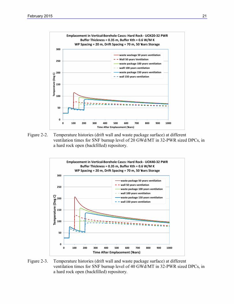
Results are shown in Figures 2.2 through 2.4. Figure 2.2 presents drift wall and buffer temperature histories for burnup of 20 GWd/MT and different ventilation times, using the nominal values for buffer conductivity and thickness. With 50 years of ventilation the peak temperature is about 115 °C, and the peak decreases to below 100 °C for the longer ventilation times. Figure 2.3 presents the corresponding plots for burnup of 40 GWd/MT. In this case for 50 years of ventilation the peak temperature is 207 °C, and for the 100- and 150-year ventilation cases the peak temperatures are 158 °C and 137 °C, respectively. Thus, for the intermediate burnup rate, ventilation periods of about 100 years would be expected for a total 150 years out-of-reactor. For the high burnup rate of 60 GWd/MT (Figure 2.4) temperatures are higher, withpeak temperature of about 289 °C for 50 years of ventilation. If buffer peak temperature is limited to 200 °C, more than 100 years of ventilation would be needed.
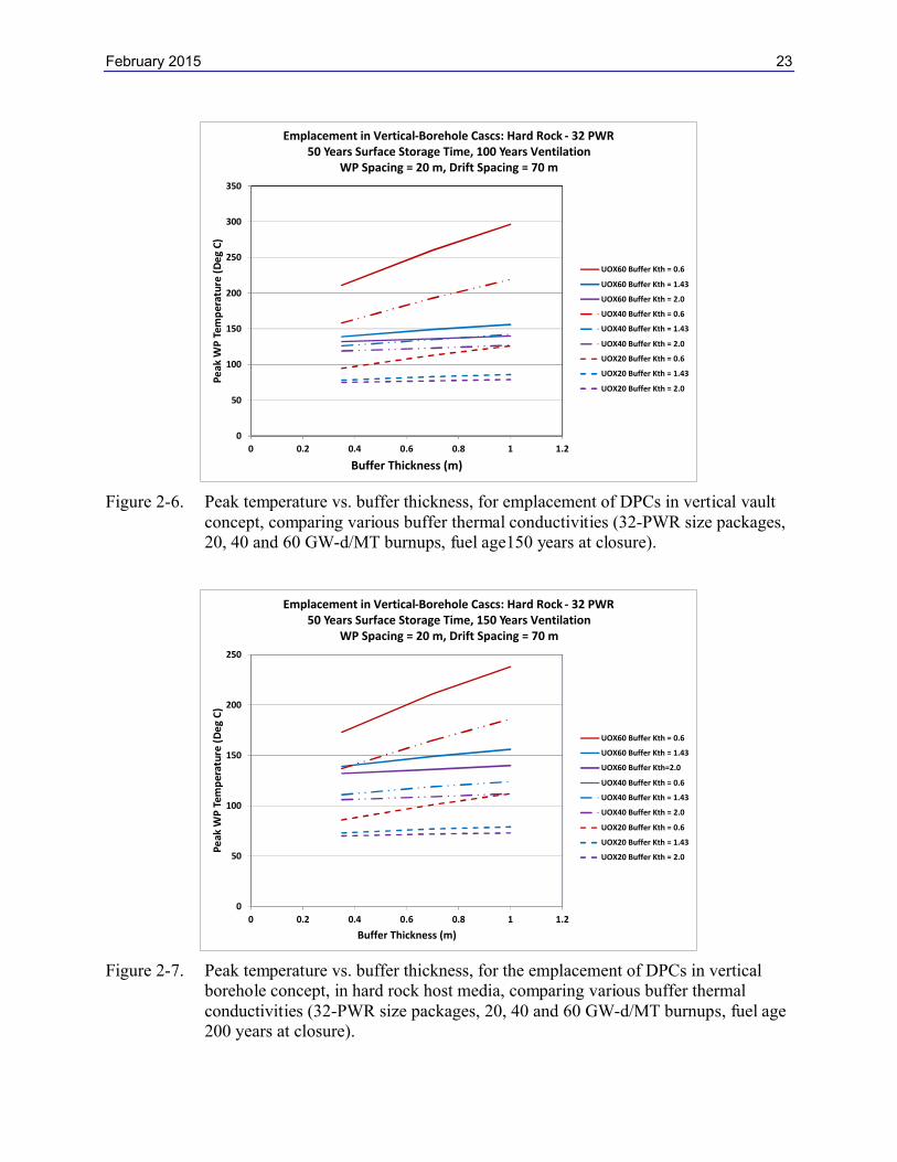
Figures 2-5 through 2-7 present the results from a parametric study that looks at the sensitivity of peak buffer temperature, to buffer thickness and buffer thermal conductivity. Figure 2-5 shows results for 50 years of ventilation (with 50 years of surface decay storage). The effect from buffer thermal conductivity is generally greater than that from buffer thickness. At higher buffer thermal conductivity values, the effect of buffer thickness on peak temperature is reduced. This suggests that buffer admixtures such as graphite, or buffer hydration early in the performance period, could limit peak temperature. Earlier buffer hydration would be expected in a saturated site with hydrostatic pressure. For the longest 150-year ventilation period (Figure 2-6) peak buffer temperature limits can be obtained for all but the hottest conditions without buffer admixture or hydration, and the hottest conditions can be managed with enhanced buffer conductivity.
February 2015 20
Figure 2-1. Conceptual diagram for storage/disposal of DPCs in drifts with vertical floor vaults, cross-sectional view.
Dual-purposecanister
Air gap for preclosure ventilation
Buffer-filled shield plug (ported for ventilation )Large-diameter
boring
Compacted dehydrated clay
buffer
February 2015 21
Figure 2-2. Temperature histories (drift wall and waste package surface) at different ventilation times for SNF burnup level of 20 GWd/MT in 32-PWR sized DPCs, in a hard rock open (backfilled) repository.
Figure 2-3. Temperature histories (drift wall and waste package surface) at different ventilation times for SNF burnup level of 40 GWd/MT in 32-PWR sized DPCs, in a hard rock open (backfilled) repository.
0
50
100
150
200
250
300
0 100 200 300 400 500 600 700 800 900 1000
Tem
per
atu
re (D
eg C
)
Time After Emplacement (Years)
Emplacement in Vertical-Borehole Cascs: Hard Rock - UOX20-32 PWRBuffer Thickness = 0.35 m, Buffer Kth = 0.6 W/M K
WP Spacing = 20 m, Drift Spacing = 70 m, 50 Years Storage
waste wackage 50 years ventilation
Wall 50 years Ventilation
waste package 100 years ventilation
walll 100 years ventilation
waste package 150 years ventilation
wall 150 years ventilation
0
50
100
150
200
250
300
0 100 200 300 400 500 600 700 800 900 1000
Tem
per
atu
re (
Deg
C)
Time After Emplacement (Years)
Emplacement in Vertical-Borehole Cascs: Hard Rock - UOX40-32 PWRBuffer Thickness = 0.35 m, Buffer Kth = 0.6 W/M K
WP Spacing = 20 m, Drift Spacing = 70 m, 50 Years Storage
waste package 50 years ventilation
wall 50 years ventilation
waste package 100 years ventilation
wall 100 years ventilation
waste package 150 years ventilation
wall 150 years ventilation

February 2015 22
Figure 2-4. Temperature histories (drift wall and waste package surface) at different ventilation times for SNF burnup level of 60 GWd/MT in 32-PWR sized DPCs, in a hard rock open (backfilled) repository.
Figure 2-5. Peak temperature vs. buffer thickness, for the emplacement of DPCs in vertical borehole concept, in hard rock host media, comparing various buffer thermal conductivities (32-PWR size packages, 20, 40 and 60 GW-d/MT burnups, fuel age100 years at closure).
0
50
100
150
200
250
300
0 100 200 300 400 500 600 700 800 900 1000
Tem
pe
ratu
re (
De
g C
)
Time After Emplacement (Years)
Emplacement in Vertical-Borehole Cascs: Hard Rock - UOX60-32 PWRBuffer Thickness = 0.35 m, Buffer Kth = 0.6 W/M K
WP Spacing = 20 m, Drift Spacing = 70 m, 50 Years Storage
waste package 50 years ventilation
wall 50 years ventilation
waste package 100 years ventilation
wall 100 years ventilation
waste package 150 years ventilation
wall 150 years ventilation
0
50
100
150
200
250
300
350
400
450
0 0.2 0.4 0.6 0.8 1 1.2
Pe
ak W
P T
em
pe
ratu
re (
De
g C
)
Buffer Thickness (m)
Emplacement in Vertical-Borehole Cascs: Hard Rock - 32 PWR50 Years Surface Storage Time, 50 Years Ventilation
WP Spacing = 20 m, Drift Spacing = 70 m
UOX60 Buffer Kth = 0.6
UOX60 Buffer Kth = 1.43
UOX60 Buffer Kth = 2.0
UOX40 Buffer Kth = 0.6
UOX40 Buffer Kth=1.43
UOX40 Buffer Kth=2.0
UOX20 Buffer Kth = 0.6
UOX20 Buffer Kth = 1.43
UOX 20 Buffer Kth = 2.0
February 2015 23
Figure 2-6. Peak temperature vs. buffer thickness, for emplacement of DPCs in vertical vaultconcept, comparing various buffer thermal conductivities (32-PWR size packages, 20, 40 and 60 GW-d/MT burnups, fuel age150 years at closure).
Figure 2-7. Peak temperature vs. buffer thickness, for the emplacement of DPCs in vertical borehole concept, in hard rock host media, comparing various buffer thermal conductivities (32-PWR size packages, 20, 40 and 60 GW-d/MT burnups, fuel age200 years at closure).
0
50
100
150
200
250
300
350
0 0.2 0.4 0.6 0.8 1 1.2
Pe
ak W
P T
emp
erat
ure
(D
eg
C)
Buffer Thickness (m)
Emplacement in Vertical-Borehole Cascs: Hard Rock - 32 PWR50 Years Surface Storage Time, 100 Years Ventilation
WP Spacing = 20 m, Drift Spacing = 70 m
UOX60 Buffer Kth = 0.6
UOX60 Buffer Kth = 1.43
UOX60 Buffer Kth = 2.0
UOX40 Buffer Kth = 0.6
UOX40 Buffer Kth = 1.43
UOX40 Buffer Kth = 2.0
UOX20 Buffer Kth = 0.6
UOX20 Buffer Kth = 1.43
UOX20 Buffer Kth = 2.0
0
50
100
150
200
250
0 0.2 0.4 0.6 0.8 1 1.2
Pe
ak W
P T
emp
erat
ure
(D
eg
C)
Buffer Thickness (m)
Emplacement in Vertical-Borehole Cascs: Hard Rock - 32 PWR50 Years Surface Storage Time, 150 Years Ventilation
WP Spacing = 20 m, Drift Spacing = 70 m
UOX60 Buffer Kth = 0.6
UOX60 Buffer Kth = 1.43
UOX60 Buffer Kth=2.0
UOX40 Buffer Kth = 0.6
UOX40 Buffer Kth = 1.43
UOX40 Buffer Kth = 2.0
UOX20 Buffer Kth = 0.6
UOX20 Buffer Kth = 1.43
UOX20 Buffer Kth = 2.0
February 2015 24
3. Summary
Thermal calculations show that 37-PWR size DPC-based waste packages could be significantly hotter than 32-PWR size packages analyzed previously. For the hard rock unsaturated “open” concept and the salt disposal concept, the greater heat output could be accommodated with slightly longer decay storage, ventilation (for the “open” concept), or enhancements such as semi-cylindrical floor cavities to improve heat transfer. Such enhancements trade directly with longer decay storage, where thermal performance is concerned.
For backfilled concepts potentially much longer decay storage or ventilation would be needed for 37-PWR size packages, even with backfill peak temperature tolerance of 200C. This is consistent with earlier results which showed that thermal goals were difficult to meet, especially for higher burnup fuel, unless the backfill has high peak temperature tolerance (200C), and admixtures (e.g., graphite particulate) to increase thermal conductivity.
Thermal analysis also showed that the vault-type disposal concepts discussed by Hardin et al. (2013) would require 100 to 150 years of ventilation (in addition to 50 years of decay storage), to meet peak buffer temperature target of 200C. Buffer thermal conductivity (e.g., use of admixtures) was found to be more effective than reducing buffer thickness, for limiting peak temperature.
References
Clayton, D.J., J.E. Bean, J.G. Arguello Jr., E.L. Hardin and F.D. Hansen 2013. “Thermal-Mechanical Modeling of a Generic High-Level Waste Salt Repository.” In: Mechanical Behaviour of Salt VII (P. Berest, M. Ghoreychi, F. Hadj-Hassen and M. Tijani, eds.). CRC Press.
Greenberg, H.R., M. Sharma, M. Sutton and A.V. Barnwell 2012. Repository Near-Field Thermal Modeling Update Including Analysis of Open Mode Design Concepts. LLNL-TR-572252. U.S. Department of Energy, Used Fuel Disposition R&D Campaign. August, 2012.
Hardin, E. and D. Sassani 2011. “Application of the Prefabricated EBS Concept in Unsaturated, Oxidizing Host Media.” Proceedings: 13th International High-Level Radioactive Waste Management Conference, Albuquerque, NM. April, 2011. American Nuclear Society. Paper #3380.
Hardin, E., J. Blink, H. Greenberg, M. Sutton, M. Fratoni, J. Carter, M. Dupont and R. Howard 2011. Generic Repository Design Concepts and Thermal Analysis (FY11). FCRD-USED-2011-000143 Rev. 2. December, 2011. U.S. Department of Energy, Used Fuel Disposition R&D Campaign.
Hardin, E., T. Hadgu, D. Clayton, R. Howard, H. Greenberg, J. Blink, M. Sharma, M. Sutton, J. Carter, M. Dupont and P. Rodwell 2012. Disposal Concepts/Thermal Load Management (FY11/12 Summary Report). FCRD-USED-2012-000219, Rev.1. U.S. Department of Energy, Used Fuel Disposition R&D Campaign.
Hardin, E., D. Clayton, R.L. Howard, J.M. Scaglione, E. Pierce, K. Banerjee, M.D. Voegele, H.R. Greenberg, J. Wen, T.A. Buscheck, J.T. Carter, T. Severynse, and W.M. Nutt 2013. Preliminary Report on Dual-Purpose Canister Disposal Alternatives (FY13) 2013. FCRD-USED-2013-000171, Rev.1. U.S. Department of Energy, Used Fuel Disposition R&D Campaign.
February 2015 25
Hardin, E. and M. Voegele 2013. Alternative Concepts for Disposal of Dual-Purpose Canisters. FCRD-USED-2013-000102, Rev.0. U.S. Department of Energy, Used Fuel Disposition R&D Campaign.
Houseworth, J.E., S. Finsterle and G.S. Bodvarsson 2002. “Flow and transport in the drift shadow in a dual-continuum model.” Journal of Contaminant Hydrology. V.62, pp.133-56.