cathodic protection of aboveground petroleum storage tanks results/2012 fall ballot...cathodic...
TRANSCRIPT
Cathodic Protection of Aboveground Petroleum Storage Tanks API RECOMMENDED PRACTICE 651 THIRD FOURTH EDITION, JANUARY 2007 2012
Cathodic Protection of Aboveground Petroleum Storage Tanks
1 Scope
1.1 The purpose of this recommended practice is to present procedures and practices for achieving effective corrosion control on aboveground storage tank bottoms through the use of cathodic protection. It This recommended practice contains provisions for the application of cathodic protection to existing and new aboveground storage tanks. Corrosion control methods based on chemical control of the environment or the use of protective coatings are not covered in detail. Note: Add “aboveground” to anywhere there is storage tank listed.
1.2 When cathodic protection is used for aboveground storage tank applications, it is the intent of this recommended practice to provide information and guidance specific to aboveground steel metallic storage tanks in hydrocarbon service. Certain practices recommended herein may also be applicable to tanks in other services. It is intended to serve only as a guide to persons interested in cathodic protection. Specific cathodic protection designs are not provided. Such designs should be developed by a person thoroughly familiar with cathodic protection practices for aboveground petroleum storage tanks.
1.3 This recommended practice does not designate specific practices for every situation because the varied conditions in which tank bottoms are installed preclude standardization of cathodic protection practices.
2 References
2.1 STANDARDS, CODES, PUBLICATIONS, AND SPECIFICATIONS
Unless otherwise specified, the most recent editions or revisions of the following standards, codes, and specifications shall, to the extent specified herein, form a part of this standard.
API Spec 12B Bolted Tanks for Storage of Production Liquids Spec 12D Field Welded Tanks for Storage of Production Liquids Spec 12F Shop Welded Tanks for Storage of Production Liquids RP 500 Recommended Practice for Classification of Locations for Electrical Installations at Petroleum Facilities RP 575 Inspection of Atmospheric and Low Pressure Storage Tanks Std 620 Design and Construction of Large, Welded, Low-pressure Storage Tanks Std 650 Welded Steel Tanks for Oil Storage RP 652 Lining of Aboveground Petroleum Storage Tank Bottoms Std 653 Tank Inspection, Repair, Alteration, and Reconstruction RP 1615 Installation of Underground Petroleum Product Storage Systems RP 1621 Bulk Liquid Stock Control at Retail Outlets RP 1632 Cathodic Protection of Underground Petroleum Storage Tanks and Piping Systems RP 2003 Protection Against Ignitions Arising Out of Static, Lightning, and Stray Currents
Comment [LZ1]: Louis K. – Item 30
Comment [LZ2]: Louis K. – Item 31
Comment [LZ3]: Louis K. – Item 32
2 API RECOMMENDED PRACTICE 651
ASTM1
C 144 Standard Specification for Aggregate for Masonry Mortar
C 778 Standard Specification for Standard Sand D 512 Standard Test Methods for Chloride Ion in Water D 516 Standard Test Method for Sulfate Ion in Water D 1557 Standard Test Methods for Laboratory Compaction Characteristics of Soil Using Modified Effort (56,000 ft-
lbf/ft3 (2,700 kN-m/m3
G 51 Standard Test Method for Measuring pH of Soil for Use in Corrosion Testing ))
G 57 Method for Field Measurement of Soil Resistivity Using the Wenner Four Electrode Method
EPA2
0376.1 Test Method for Sulfide—Titrimetric Iodine
NACE3
Peabody’s Control of Pipeline Corrosion, ISBN 1-57590-114-5
TM0497 Measurement Techniques Related to Criteria for Cathodic Protection on Underground or Submerged Metallic Piping Systems
RP0177SP0177-2007 Mitigation of Alternating Current and Lightning Effects on Metallic Structures and Corrosion Control Systems
RP0193-2001 External Cathodic Protection of On-Grade Metallic Storage Tank Bottoms RP0285SP0285-2011 Corrosion Control of Underground Storage Tank Systems by Cathodic Protection RP0388SP0388-2007 Impressed Current Cathodic Protection of Internal Submerged Surfaces of Steel Water Storage
Tanks RP0572SP0572-2007 Design, Installation, Operation, and Maintenance of Impressed Current Deep Groundbeds RP0575SP0575-2007 Internal Cathodic Protection Systems in Oil Treating Vessels TPC 11 A Guide to the Organization of Underground Corrosion Control Coordinating Committees
NFPA4
30 Flammable and Combustible Liquids Code
70 National Electrical Code
PEI5
RP100 Recommended Practices for the Installation of Underground Liquid Storage Systems
2.2 OTHER REFERENCES
Although not cited in the text of this recommended practice, the following publications provide additional information pertaining to cathodic protection of aboveground storage tanks in petroleum service.
API Std 2610 Design, Construction, Operation, Maintenance & Inspection of Terminal and Tank Facilities
UL6
142 Steel Aboveground Tanks for Flammable and Combustible Liquids
1ASTM International, 100 Bar Harbor Drive, West Conshohocken, Pennsylvania 19428, www.astm.org. 2U.S. Environmental Protection Agency, Ariel Rios Building, 1200 Pennsylvania Avenue, N.W., Washington, D.C. 20460, www.epa.gov. 3NACE International (formerly the National Association of Corrosion Engineers), 1440 South Creek Drive, P.O. Box 218340, Houston, Texas, 77218-8340, www.nace.org. 4National Fire Protection Association, 1 Batterymarch Park, PO Box 9101, Quincy, Massachusetts 02269-9101, www.nfpa.org. 5Petroleum Equipment Institute, P.O. Box 2380, Tulsa, Oklahoma 74101-2380. www.pei.org. 6Underwriters Laboratories, 333 Pfingsten Road, North brook, Illinois 60062, www.ul.com.
Comment [DD4]: Donald Drake – Item 17
CATHODIC PROTECTION OF ABOVEGROUND PETROLEUM STORAGE TANKS 3
3 Definitions
Definitions in this section reflect the common usage among practicing corrosion control personnel. In many cases, in the interests of brevity and practicality, the strict scientific definitions have been abbreviated or paraphrased.
3.1 aboveground storage tank:
3.2
An on-grade, stationary, uniformly supported container, usually cylindrical in shape, consisting of a metallic roof, shell, bottom, and support structure where more than 90% of the tank volume is above surface grade.
anode: The electrode of an electrochemical cell at which oxidation (corrosion) occurs. Antonym: cathode
3.3
.
anode bed:
3.4
Consists of one or more anodes installed below the earth’s surface for the purpose of supplying cathodic protection.
backfill:
3.5
Commercial, uniformly conductive material placed in a hole to fill the space around anodes, vent pipe, and buried components of a cathodic protection system. Anodes can be prepackaged with backfill material for ease of installation.
breakout piping/tanks:
3.6
Piping/tanks used to relieve surges in a hazardous liquid pipeline system or piping/tanks used to receive and store hazardous liquid transported by a pipeline for reinjection and continued transportation by pipeline.
cathode: The electrode of an electrochemical cell at which a reduction reaction occurs. Antonym: anode
3.7
.
cathodic protection:
3.8
A technique to reduce corrosion of a metal surface by making the entire surface the cathode of an electrochemical cell.
chime (or chine):
3.9
The portion of the tank bottom steel floor plate that extends horizontally past the outside vertical surface of the shell (i.e., the external lip formed at the base of the tank where the bottom steel floor plate protrudes and is welded to the bottom of the shell, around the entire tank perimeter). Also referred to as bottom extension.
coke breeze:
3.10
A commercial carbonaceous backfill material.
concentration corrosion cell:
(NACE definition: An electrochemical cell, the electromotive force of which is caused by a difference in concentration of some component in the electrolyte. [This difference leads to the formation of discrete cathodic and anodic regions.])
A form of localized corrosion initiated by the difference in metal ion or oxygen concentration due to crevices, or deposits or differences in oxygen concentration on the tank bottom.
3.11 continuity bond:
3.12
A metallic connection that provides electrical continuity.
corrosion:
3.13
The deterioration of a material, usually a metal, that results from a reaction with its environment.
current density:
3.14
The current per unit area flowing to or from a metallic surface.
current requirement test:
3.15
A test where the use of direct current flow from a temporary anode bed to the structure to be protected is used to determine the amount of current necessary to protect the structure.
deep anode bed:
3.16
One or more anodes installed vertically at a nominal depth of 15 m (50 ft) or more below the earth’s surface in a single drilled hole for the purpose of supplying cathodic protection.
differential aeration cell: An electrochemical cell the electromotive force of which is due to a difference in air (oxygen) concentration at one electrode part of the tank bottom as compared with that at another electrode part of the tank bottom of the same material.
Comment [LZ5]: Louis K. – Item 33
Comment [LZ6]: Louis K. – Item 34
4 API RECOMMENDED PRACTICE 651
3.17 electrical isolation:
3.18
The condition of being electrically separated from other metallic structures.
electrochemical cell:
3.19
An electrochemical system consisting of an anode and a cathode immersed in an electrolyte so as to create an electrical circuit. The anode and cathode may be separate metals or dissimilar areas on the same metal. The cell includes the external circuit, which permits the flow of electrons from the anode toward the cathode.
electrode potential:
3.20
The potential of an electrode as measured against a standard reference electrode. The electrode potential does not include any voltage measurement errors due to the passage of current through the resistance of the metallic or electrolytic paths.
electrolyte:
3.21
A chemical substance containing ions that migrate in an electric field. For the purposes of this recommended practice, electrolyte refers to the soil or water adjacent to and in contact with the bottom of an aboveground petroleum storage tank, including the contaminants and chemicals contained therein.
environmental cracking:
3.22
The brittle fracture of a normally ductile material in which the corrosive effect of the environment is a causative factor.
external circuit:
3.23
Consists of the wires, metallic connectors, measuring devices, current sources, etc., that are used to bring about or measure the desired electrical conditions within an electrochemical cell. It is this portion of the cell through which electrons travel.
external liner:
3.24
A system or device, such as a non-conductive membrane, installed beneath a storage tank, in or on the tank dike, to contain any accidentally escaped product.
foreign structure:
3.25
Any metallic structure that is not intended as a part of a system under cathodic protection.
galvanic anode:
3.26
A metal that, because of its relative position in the galvanic series, provides sacrificial protection to another metal that is more noble, when electrically coupled in an electrolyte. These anodes are the source of current in galvanic or sacrificial cathodic protection.
galvanic cathodic protection:
3.27
The reduction or prevention of corrosion of a metal in an electrolyte by electrically connecting it to a more anodic metal.
galvanic series:
3.28
A list of metals and alloys arranged according to their relative potentials in a given environment.
holiday:
3.29
A discontinuity in a protective coating that exposes the underlying substrate to the environment.
impressed current:
3.30
An electric current supplied by a device employing a power source that is external to the electrode system. (An example is the direct current output of a cathodic protection rectifier.)
interference bond:
3.31
A metallic connection designed to control stray electrical current discharge from a metallic structure.
IR drop:
3.32
The voltage generated across a resistance by an electrical current in accordance with Ohm’s Law: E = I × R. For the purpose of this recommended practice, the most significant IR drop is the portion of a structure-to-soil potential caused by current flow through a resistive electrolyte from the anode to the structure.
isolation: See electrical isolation
3.33
.
membrane:
3.34
A thin, continuous sheet of nonconductive synthetic material used to contain and/or separate two different environments.
oxidation: The loss of electrons by a constituent of a chemical reaction.
CATHODIC PROTECTION OF ABOVEGROUND PETROLEUM STORAGE TANKS 5
3.35 polarization:
3.36
The change from the open-circuit potential of an electrode as a result of current across the electrode/electrolyte interface.
rectifier:
3.37
A device for converting alternating current to direct current. Usually includes a step-down AC transformer, a silicon or selenium stack (rectifying elements), meters, and other accessories when used for cathodic protection purposes.
reduction:
3.38
The gain of electrons by a constituent of a chemical reaction.
reference electrode:
3.39
An electrode whose open-circuit potential is constant under similar conditions of measurement.
release prevention barrier (RPB):
3.40
Includes steel bottoms (when used in a double bottom or secondary containment system), synthetic materials, clay liners, and all other barriers or combination of barriers placed in the bottom of, or under an aboveground storage tank, which have the following functions: (a) preventing the escape of stored product, and (b) containing or channeling released material for leak detection.
resistor:
3.41
A device used within an electrical circuit to control current flow.
secondary containment:
3.42
A device or system used to control the accidental escape of a stored product so it may be properly recovered or removed from the environment.
shallow anode bed:
3.43
A group of cathodic protection anodes installed individually, spaced uniformly, and typically buried less than 20 ft (6 m) below grade.
shunt:
3.44
A conductor of a known electrical resistance through which current flow may be determined by measurement of the voltage across the conductor and calculation using Ohm’s Law.
stray current:
3.45
Current flowing through paths other than the intended circuit.
stray current corrosion:
3.46
Corrosion resulting from direct current flow through paths other than the intended circuit.
stress corrosion cracking:
3.47
The fracture of a metal by the combined action of corrosion and tensile stress. The fracture occurs under a tensile stress that may be well below the tensile strength or even the yield strength of the material.
structure-to-electrolyte voltage (also structure-to-soil potential or pipe-to-soil potential):
3.48
The voltage difference between a metallic structure and the electrolyte which is measured with a reference electrode in contact with the electrolyte.
structure-to-structure voltage (also structure-to structure potential difference):
3.49
The difference in voltage between metallic structures in a common electrolyte.
tank pad:
3.50
The material immediately adjacent to the exterior steel bottom of an aboveground storage tank.
test lead:
3.51
An electrically conductive wire or cable attached to a structure and terminated in a test station. It is used for the measurement of structure-to-electrolyte potentials and other measurements.
test station:
3.52
A small enclosure or housing that is the termination point of one or more test leads.
voltage:
3.53
An electromotive force, or a difference in electrode potentials expressed in volts. Also known as a potential.
water bottom: A water layer in the bottom of a tank caused by separation of water and product due to differences in solubility and specific gravity.
6 API RECOMMENDED PRACTICE 651
4 Corrosion of Aboveground Steel Storage Tanks
4.1 INTRODUCTION
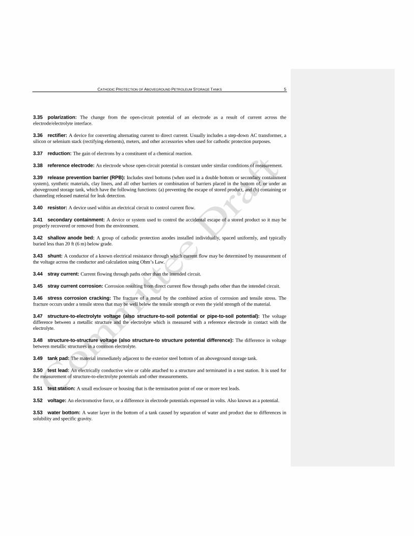
4.1.1 Corrosion may be defined as the deterioration of a metal resulting from a reaction with its environment. Corrosion of steel structures is an electrochemical process. For the corrosion process to occur, areas with different electrical potentials must exist on the metal surface. These areas must be electrically connected and in contact with an electrolyte.
There are four components required for a corrosion cell: an anode, a cathode, a metallic path connecting the anode and cathode, and an electrolyte (see Figure 1). The role of each component in the corrosion cell is as follows:
a.At the anode, the base metal goes into solution (corrodes) by releasing electrons and forming positive metal ions. For steel, the anodic reaction is:
Fe Fe+2 2e–+→
b.At the cathode, chemical reactions take place using electrons released at the anode. No corrosion takes place at the cathode. One common cathodic reaction is:
O2 2H2O 4e–+ + 4OH–→
c.The metallic path provides a way for electrons released at the anode to flow to the cathode. d.The electrolyte contains ions and conducts current from the anode to the cathode by ionic movement. The electrolyte contains both negatively charged ions called anions and positively charged ions called cations that are attracted to the anode and cathode, respectively. Moist soil is the most common electrolyte for external surfaces of the tank bottom, while water and sludge generally are the electrolytes for the internal surfaces.
4.1.2 There are many forms of corrosion. The two most common types relative to tank bottoms are general and localized (pitting) corrosion. In general corrosion, thousands of microscopic corrosion cells occur on an area of the metal surface resulting in relatively uniform metal loss. In localized (pitting) corrosion, the individual corrosion cells are larger and distinct anodic and cathodic areas can be identified. Metal loss in this case may be concentrated within relatively small areas with substantial areas of the surface unaffected by corrosion.
Figure 1—Electrochemical Corrosion Cell
4.1.2
4.1.3 The composition of the metal is a factor in determining which areas on a metal surface become anodes or cathodes. Differences in electrochemical potential between adjacent areas can result from uneven distribution of alloying elements or contaminants within the metal structure. Corrosion can also be caused by differences between weld metal, heat affected zone, and parent metal.
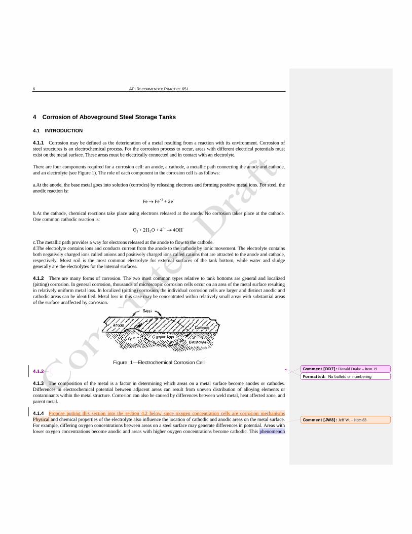
4.1.4 Propose putting this section into the section 4.2 below since oxygen concentration cells are corrosion mechanisms Physical and chemical properties of the electrolyte also influence the location of cathodic and anodic areas on the metal surface. For example, differing oxygen concentrations between areas on a steel surface may generate differences in potential. Areas with lower oxygen concentrations become anodic and areas with higher oxygen concentrations become cathodic. This phenomenon
Comment [DD7]: Donald Drake – Item 19
Formatted: No bullets or numbering
Comment [JW8]: Jeff W. – Item 83
CATHODIC PROTECTION OF ABOVEGROUND PETROLEUM STORAGE TANKS 7
can cause corrosion of steel tank bottoms on a homogeneous sand pad, and or when contaminated with clay or other debris or natural soil that does not have a uniform consistency (see Figure 2).
Figure 2—Oxygen Concentration Cell Caused by Rocks or Clay in Tank Pad
4.1.4
4.1.5 Soil characteristics substantially affect the type and rate of corrosion on a structure in contact with soil. For example, dissolved salts influence the current carrying capacity of the soil electrolyte and help determine reaction rates at the anodic and cathodic areas. Moisture content, pH, oxygen concentration, and other factors interact in a complex fashion to influence corrosion.
4.2 CORROSION MECHANISMS
4.2.1 Stray Current Corrosion
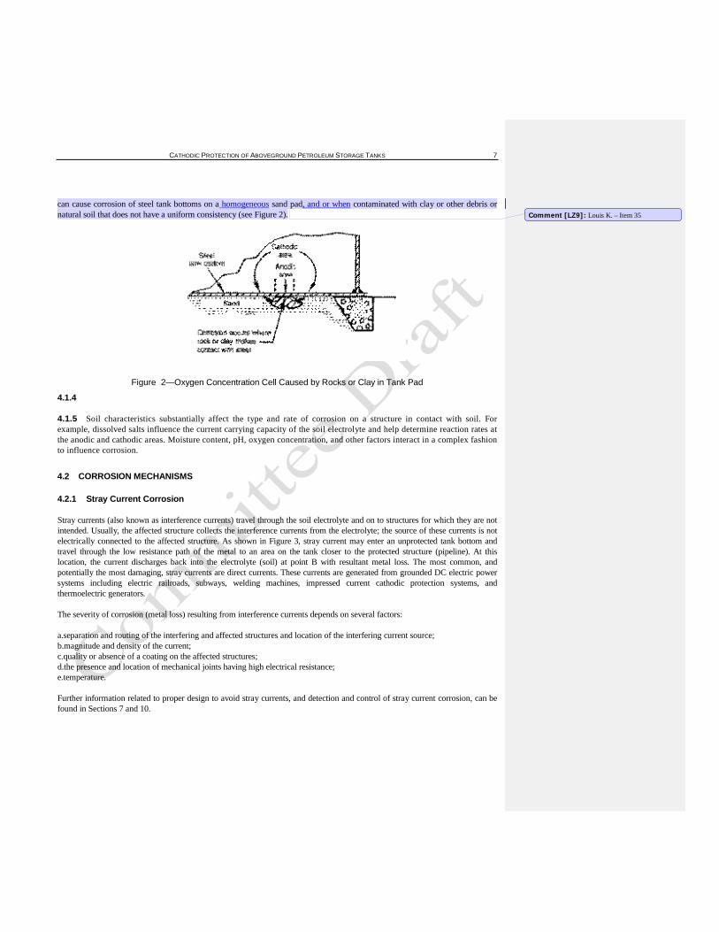
Stray currents (also known as interference currents) travel through the soil electrolyte and on to structures for which they are not intended. Usually, the affected structure collects the interference currents from the electrolyte; the source of these currents is not electrically connected to the affected structure. As shown in Figure 3, stray current may enter an unprotected tank bottom and travel through the low resistance path of the metal to an area on the tank closer to the protected structure (pipeline). At this location, the current discharges back into the electrolyte (soil) at point B with resultant metal loss. The most common, and potentially the most damaging, stray currents are direct currents. These currents are generated from grounded DC electric power systems including electric railroads, subways, welding machines, impressed current cathodic protection systems, and thermoelectric generators.
The severity of corrosion (metal loss) resulting from interference currents depends on several factors:
a.separation and routing of the interfering and affected structures and location of the interfering current source; b.magnitude and density of the current; c.quality or absence of a coating on the affected structures; d.the presence and location of mechanical joints having high electrical resistance; e.temperature.
Further information related to proper design to avoid stray currents, and detection and control of stray current corrosion, can be found in Sections 7 and 10.
Comment [LZ9]: Louis K. – Item 35
8 API RECOMMENDED PRACTICE 651
Figure 3—Example of Stray Current Corrosion of an Unprotected Tank Bottom
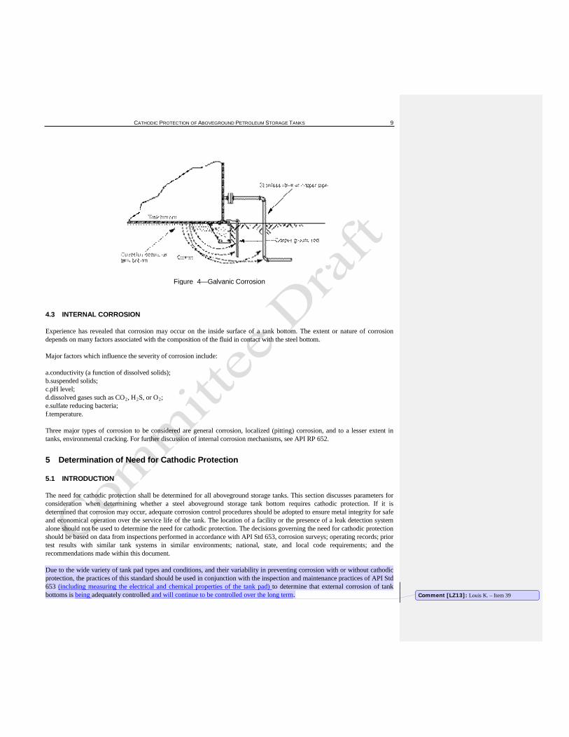
4.2.2 Galvanic Corrosion
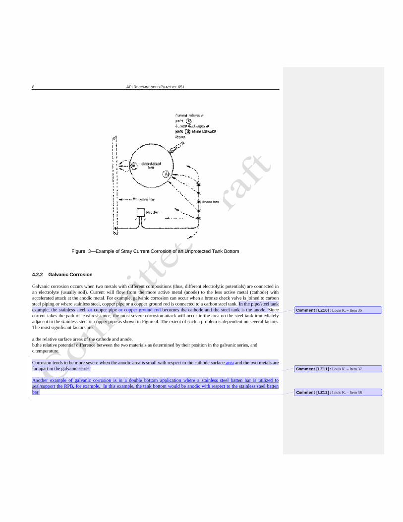
Galvanic corrosion occurs when two metals with different compositions (thus, different electrolytic potentials) are connected in an electrolyte (usually soil). Current will flow from the more active metal (anode) to the less active metal (cathode) with accelerated attack at the anodic metal. For example, galvanic corrosion can occur when a bronze check valve is joined to carbon steel piping or where stainless steel, copper pipe or a copper ground rod is connected to a carbon steel tank. In the pipe/steel tank example, the stainless steel, or copper pipe or copper ground rod becomes the cathode and the steel tank is the anode. Since current takes the path of least resistance, the most severe corrosion attack will occur in the area on the steel tank immediately adjacent to the stainless steel or copper pipe as shown in Figure 4. The extent of such a problem is dependent on several factors. The most significant factors are:
a.the relative surface areas of the cathode and anode, b.the relative potential difference between the two materials as determined by their position in the galvanic series, and c.temperature.
Corrosion tends to be more severe when the anodic area is small with respect to the cathode surface area and the two metals are far apart in the galvanic series.
Another example of galvanic corrosion is in a double bottom application where a stainless steel batten bar is utilized to seal/support the RPB, for example. In this example, the tank bottom would be anodic with respect to the stainless steel batten bar.
Comment [LZ10]: Louis K. – Item 36
Comment [LZ11]: Louis K. – Item 37
Comment [LZ12]: Louis K. – Item 38
CATHODIC PROTECTION OF ABOVEGROUND PETROLEUM STORAGE TANKS 9
Figure 4—Galvanic Corrosion
4.3 INTERNAL CORROSION
Experience has revealed that corrosion may occur on the inside surface of a tank bottom. The extent or nature of corrosion depends on many factors associated with the composition of the fluid in contact with the steel bottom.
Major factors which influence the severity of corrosion include:
a.conductivity (a function of dissolved solids); b.suspended solids; c.pH level; d.dissolved gases such as CO2, H2S, or O2e.sulfate reducing bacteria;
;
f.temperature.
Three major types of corrosion to be considered are general corrosion, localized (pitting) corrosion, and to a lesser extent in tanks, environmental cracking. For further discussion of internal corrosion mechanisms, see API RP 652.
5 Determination of Need for Cathodic Protection
5.1 INTRODUCTION
The need for cathodic protection shall be determined for all aboveground storage tanks. This section discusses parameters for consideration when determining whether a steel aboveground storage tank bottom requires cathodic protection. If it is determined that corrosion may occur, adequate corrosion control procedures should be adopted to ensure metal integrity for safe and economical operation over the service life of the tank. The location of a facility or the presence of a leak detection system alone should not be used to determine the need for cathodic protection. The decisions governing the need for cathodic protection should be based on data from inspections performed in accordance with API Std 653, corrosion surveys; operating records; prior test results with similar tank systems in similar environments; national, state, and local code requirements; and the recommendations made within this document.
Due to the wide variety of tank pad types and conditions, and their variability in preventing corrosion with or without cathodic protection, the practices of this standard should be used in conjunction with the inspection and maintenance practices of API Std 653 (including measuring the electrical and chemical properties of the tank pad) to determine that external corrosion of tank bottoms is being adequately controlled and will continue to be controlled over the long term. Comment [LZ13]: Louis K. – Item 39
10 API RECOMMENDED PRACTICE 651
5.1.1 New Aboveground Storage Tanks
Corrosion control by cathodic protection for new aboveground storage tanks should be included evaluated in the initial design unless a detailed study indicates it is not needed., Ifand if cathodic protection is applied, it should be maintained during the service life of the tank.
5.1.2 Existing Aboveground Storage Tanks
An evaluation should be conducted Studies should be made within a suitable time frame in accordance with API Std 653 to determine the need to installconcerning the possible need for cathodic protection. When these studies indicate that corrosion will affect the safe or economic operation of the tanksystem, adequate corrosion control measures should be used.installed. These corrosion control measures can include cathodic protection and linings (see API RP 652.)
5.1.3 Internal Cathodic Protection
Pure hydrocarbon fluids are usually not corrosive and do not require corrosion control for internal surfaces. However, based upon experience, internal corrosion willmay occur in aboveground storage tanks that have internal surfaces exposed to water, sediments, or other contaminants. Generally, coatings are used to reduce or eliminate corrosion on internal surfaces. For tanks in petroleum service, internal cathodic protection in conjunction with coatings can be used andhas not gained widespread use, but under certain conditions it can be effective in protecting against corrosion at holidays in the coating. For more detailed information on internal cathodic protection, see NACE RP0575 SP0575 and RP0388SP0388.
5.1.4 Limitations of External Cathodic Protection
Cathodic protection is an effective means of corrosion control only if it is possible to pass electrical current between the anode and cathode (tank bottom). Many factors can either reduce or eliminate the flow of electrical current and, therefore, may limit the effectiveness of cathodic protection in some cases or preclude its use in others. Such factors include:
a.tank pads such as concrete, asphalt, or oiled sand; b.an impervious a non-conductive external liner between the tank bottom and anodes (unless anodes installed between liner and tank bottom); c.high resistance resistivity soil or coarse/large rock aggregate pads; d.old storage tank bottoms left in place when a new bottom is installed.
These and other related factors are discussed in more detail in 5.3 and 5.4. It should be recognized that external cathodic protection has no effect on internal corrosion.
5.2 TANK HISTORY
5.2.1 General
Before determining the need for cathodic protection, a full evaluation of tank history is advised. If this evaluation indicates that external corrosion is a known or potential concern, then cathodic protection or other corrosion control measures should be used. If internal corrosion is known to be a problem, use of a lining should be considered (refer to API RP 652); in certain cases, internal cathodic protection in conjunction with a lining may be appropriate. The following items should be investigated and determined.
5.2.2 Tank Design/Construction History
The following items should be investigated and determined in the evaluation of tank design/construction history:
Comment [MS14]: Michael Surkein – Item 2
Comment [MS15]: Michael Surkein – Item 3
Comment [MS16]: Michael Surkein – Item 4
Comment [DD17]: Donald Drake – Item 18
Comment [MS18]: Michael Surkein – Item 5
Comment [LZ19]: Louis K. – Item 40
CATHODIC PROTECTION OF ABOVEGROUND PETROLEUM STORAGE TANKS 11
a.ringwall foundation and tank pad design; b.site plan, including tank farm layout; c.construction dates; d.soil properties and resistivity electrical and chemical properties; e.water table; f.presence and type(s) of coatings or linings; g.previous repairs; h.change in soil conditions; i.impervious external liner conductive and non-conductive release prevention barriers; j.secondary bottom; k.existing cathodic protection on nearby structures; l.maintenance history; m.expected life; n.rectifier and anode bed location(s)
n. o. .tank bottom design, coned up, coned down, “w” type, or flat bottom
5.2.3 Type of Service
The following items should be investigated and determined in the evaluation of types of service:
a.type of product stored; b.product temperature; c.presence and depth of water bottoms; d.frequency of fill and discharge.
5.2.4 Inspection/Corrosion History
The following items should be investigated and determined in the evaluation of inspection/corrosion history:
a.tank inspection per API Std 653; b.corrosion rate records; c.corrosion problems on nearby tanks; d.corrosion problems on tanks of similar construction; e.stray current problems; f.design and performance of previous corrosion protection systems; g.structure-to-soil potential surveys.
g. h. tank pad chemical and electrical testing during internal inspections
5.2.5 Other Factors
The following items should be investigated and determined in the evaluation of other factors:
a.foreign buried metallic structures; b.foreign cathodic protection systems.
Formatted: No bullets or numbering
Comment [LZ20]: Louis K. – Item 41
Formatted: No bullets or numbering
Comment [LZ21]: Louis K. – Item 42
12 API RECOMMENDED PRACTICE 651
5.3 TANK PAD AND SOIL CONDITIONS
5.3.1 Introduction
5.3.1.1 Different types of pads are constructed for aboveground storage tanks due to a wide variety of surface, subsurface, and climatic conditions. The pad material under the tank has a significant effect on external corrosion of the tank bottom and can influence the effectiveness and applicability of external cathodic protection. It is very important to ensure that there is no debris such as, rocks, lumps of clay, welding electrodes, paper, plastic, wood, etc. in the pad material. The pad material particles should be fine and uniform.
Tanks should be built on an elevated berm to allow adequate drainage away from the tank bottom. The use of fine particles will provide a denser pad to help reduce the influx and outflow of oxygen from the perimeter of the tank as it is emptied and filled. If large particle sizes are used, differential aeration corrosion may result at points where the large particles or debris contact the steel tank bottom. In this case, cathodic protection current will be shielded and may not be effective in eliminating corrosion the pitting.
There are a wide variety of pad materials available, some of which may actually prevent the beneficial effects of cathodic protection. Conversely, there are situations where some of these materials, when properly selected and installed, can be beneficial in reducing corrosion to the extent that cathodic protection may not be needed, as described later in this section.
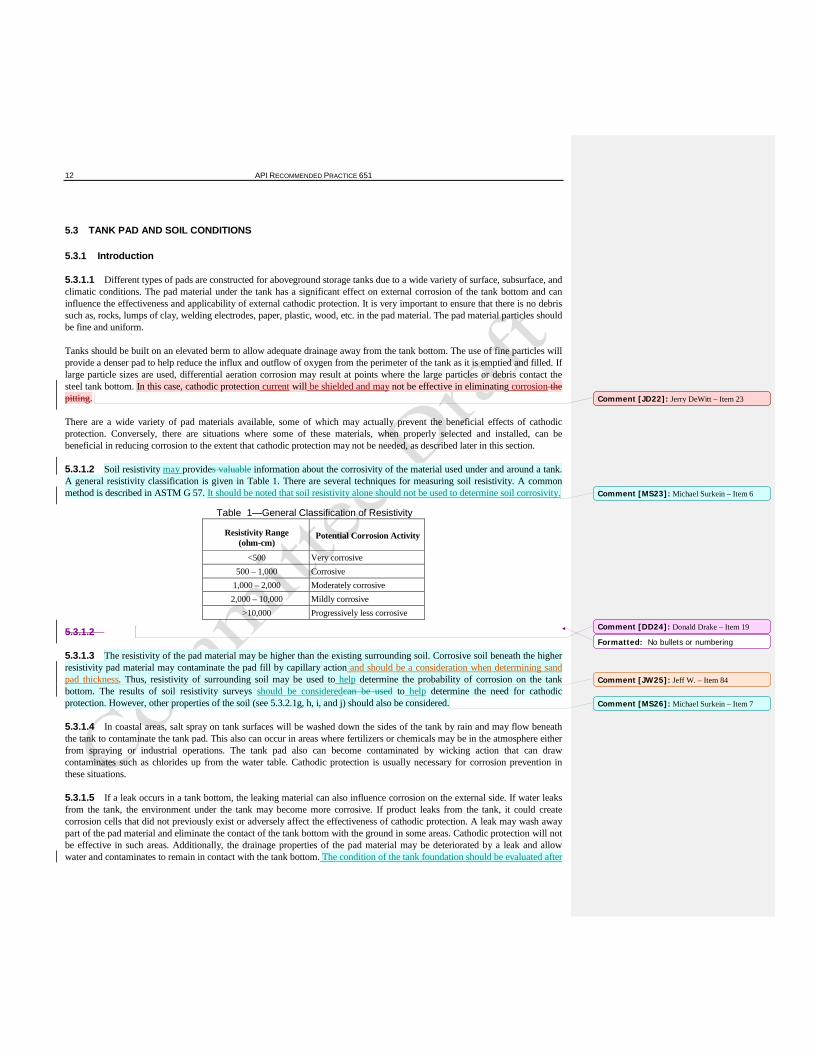
5.3.1.2 Soil resistivity may provides valuable information about the corrosivity of the material used under and around a tank. A general resistivity classification is given in Table 1. There are several techniques for measuring soil resistivity. A common method is described in ASTM G 57. It should be noted that soil resistivity alone should not be used to determine soil corrosivity.
Table 1—General Classification of Resistivity
Resistivity Range (ohm-cm)
Potential Corrosion Activity
<500 Very corrosive 500 – 1,000 Corrosive
1,000 – 2,000 Moderately corrosive 2,000 – 10,000 Mildly corrosive
>10,000 Progressively less corrosive
5.3.1.2
5.3.1.3 The resistivity of the pad material may be higher than the existing surrounding soil. Corrosive soil beneath the higher resistivity pad material may contaminate the pad fill by capillary action and should be a consideration when determining sand pad thickness. Thus, resistivity of surrounding soil may be used to help determine the probability of corrosion on the tank bottom. The results of soil resistivity surveys should be consideredcan be used to help determine the need for cathodic protection. However, other properties of the soil (see 5.3.2.1g, h, i, and j) should also be considered.
5.3.1.4 In coastal areas, salt spray on tank surfaces will be washed down the sides of the tank by rain and may flow beneath the tank to contaminate the tank pad. This also can occur in areas where fertilizers or chemicals may be in the atmosphere either from spraying or industrial operations. The tank pad also can become contaminated by wicking action that can draw contaminates such as chlorides up from the water table. Cathodic protection is usually necessary for corrosion prevention in these situations.
5.3.1.5 If a leak occurs in a tank bottom, the leaking material can also influence corrosion on the external side. If water leaks from the tank, the environment under the tank may become more corrosive. If product leaks from the tank, it could create corrosion cells that did not previously exist or adversely affect the effectiveness of cathodic protection. A leak may wash away part of the pad material and eliminate the contact of the tank bottom with the ground in some areas. Cathodic protection will not be effective in such areas. Additionally, the drainage properties of the pad material may be deteriorated by a leak and allow water and contaminates to remain in contact with the tank bottom. The condition of the tank foundation should be evaluated after
Comment [JD22]: Jerry DeWitt – Item 23
Comment [MS23]: Michael Surkein – Item 6
Comment [DD24]: Donald Drake – Item 19
Formatted: No bullets or numbering
Comment [JW25]: Jeff W. – Item 84
Comment [MS26]: Michael Surkein – Item 7
CATHODIC PROTECTION OF ABOVEGROUND PETROLEUM STORAGE TANKS 13
a leak to access change in corrosion properties of the foundation. Leaked asphalt (for example) under a tank may partially shield cathodic protection current from reaching the tank bottom.
5.3.2 Sand Pad
Clean sand is the most common material used as a pad beneath aboveground storage tank bottoms. The use of clean sand alone normally does not eliminate the need for cathodic protection since corrosion may occur due to intrusion of water from rain, snow, or a shallow water table, condensation, or other corrosion described in section 4 above. Guidelines for the chemical and electricalanalysis of the sand for corrosive contaminants are discussed in 5.3.2.1f, g, h, i, and j.
These are suggested guidelines or considerations for the construction of aboveground storage tank bottom sand pad (non oiled) that were developed from practices represented by industry experience.
5.3.2.1 Sand Pad Material
The following are issues to sand pad material.
a.The sand should be clean, screened, and debris free (i.e., no wood, sticks, vegetation, paper, rocks; clay, silt, or other soil; welding rods or other metallic or non-metallic objects; etc.). b.Cleaning should be done at the supply source and is accomplished by mechanical washing with water that will not alter the chemical composition or electrical resistance of the sand material.
CAUTION: A municipal potable water supply may not be acceptable because of chlorination which may produce high chloride levels.
c.Masonry mortar quality sand is sometimes specified. d.Sand should conform to specifications such as one of the following: 1) ASTM C 778 type “20-30 sand” or equivalent, 2) ASTM C 778 “graded sand” or equivalent, or 3) ASTM C 144 or equivalent. e.Portland cement, at an approximate 33:1 sand to cement ratio, or lime, at an approximate 95:5 sand to lime ratio, is sometimes added at the supply source to elevate pH levels and/or to facilitate good compaction.
CAUTION: Do not use an excessive amount of portland cement or lime as the pad material should be somewhat yielding and not hard like concrete in order to allow the tank bottom to uniformly bear on the sand pad material when loaded and make intimate contact with it.
f.Electrical resistivity of the sand material is a commonly used method for determining its corrosivity because it is relatively easy to measure. The resistivity of a soil depends on its chemical properties, moisture content, and temperature. The resistivity of the sand material may be determined in accordance with ASTM G 57, or equivalent. The results of the testing shall be forwarded to the cathodic protection designer. g.Measuring pH indicates the hydrogen ion content of a soil. Corrosion of steel is fairly independent of pH when it is in the range of 5.0 to 8.0. The rate of corrosion increases appreciably when pH is < 5.0 and decreases when pH is > 8.0. pH may be determined in accordance with ASTM G 51 or equivalent. h.Chlorides will affect the resistivity of soil, and act as a depolarizing agent which will increase the current requirement for cathodic protection of steel. Pitting corrosion on steel can begin at chloride levels of 10 ppm. Chloride content may be determined in accordance with ASTM D 512 or equivalent. There is currently no industry consensus on an acceptable range for chloride levels, therefore the tank owner/operator should specify the acceptable chloride level. There are practical and possible economic limitations in achieving minimum levels of chloride content. i.Sulfate levels >200 ppm frequently indicate high concentrations of organic matter. Sulfate content may be determined in accordance with ASTM D 516 or equivalent. There is currently no industry consensus on an acceptable range for sulfate levels, therefore the tank owner/operator should specify the acceptable sulfate level. There are practical and possible economic limitations in achieving minimum levels of sulfate content. j.Sulfide levels > 0.10 ppm, may indicate that sulfates have been reduced by bacteria. Sulfide content may be determined in accordance with EPA 0376.1 or equivalent. There is currently no industry consensus on an acceptable range for sulfide levels, therefore the tank owner/operator should specify the acceptable sulfide level. There are practical and possible economic limitations in achieving minimum levels of sulfide content.
Comment [MS27]: Michael Surkein – Item 8
Comment [LZ28]: Louis K. – Item 43
Comment [LZ29]: Louis K. – Item 44
Comment [LZ30]: Louis K. – Item 45
14 API RECOMMENDED PRACTICE 651
k.Random testing of the sand material should be conducted at the supply source to determine if the electrical resistivity and chemical properties are at acceptable levels. Sand samples used to determine the properties of the material should be taken from the actual material that is to be used during construction. If test results do not meet owner/operator specified levels then additional steps such as rewashing and/or adding portland cement or lime, or secure another source of sand, may need to be taken.
5.3.2.2 Tank Sand Pad Construction
The following are considerations when constructing tank pads.
a.Care should be taken to use clean mixing, handling, and construction equipment to ensure that the sand pad material remains free from foreign matter and debris. b.Sand is often installed by loose lifts in maximum layering of 6 in. – 8 in. (15 cm – 20 cm) thickness. The total depth or thickness of the sand pad is determined by engineering design and tank loading requirements and may be from one to several layers thick dependent upon owner/operator specifications. c.Mechanical vibratory compaction and rolling is suggested to be done for each layer to achieve compaction to 95% of the maximum dry density per ASTM D 1557 or equivalent.
CAUTION: Compaction by water flooding is not recommended because the water used to flood the sand pad may cause contamination and deterioration of the original chemical and electrical properties of the sand material. Additionally, flooding can cause bulking of the pad and subsequent adverse settlement when loaded, possibly causing damage to the tank bottom, attached piping or other appurtenances.
d.The bottom side of each steel plate to be used for tank bottom construction should be inspected immediately before placement onto the pad to ensure that any contaminating debris that is adhered to it (e.g., mud) is removed and that the plate surface is clean. e.Cathodic protection and leak detection materials/components may be placed in, or pass through, the sand pad only in accordance with owner/operator approved designs. Otherwise, the pad shall be completely free of any material other than the specified sand material.
5.3.3 Continuous Concrete Pad
5.3.3.1 A properly designed concrete tank pad constructed on stable, properly prepared subsoil may be effective in eliminating intrusion of groundwater, soil-side corrosion, and the need for cathodic protection. Preparation of a stable soil to support the concrete slab is very important to ensure the continued integrity of the pad. Unstable soil may induce cracks in the slab through which water and contaminants can permeate to the steel tank bottom and provide a corrosive environment.
5.3.3.2 Although corrosion from the soil may be prevented by a concrete pad, there may still be a collection of moisture between the tank bottom and the pad due to condensation, blowing rain or snow, or flooding due to inadequate drainage, rain water from the roof of the tank flowing down the tank walls, for example. Corrosion may occur due to this moisture accumulation. Cathodic protection is generally not considered an effective way to combat this corrosion. A free-draining concrete pad or ringwall and a seal around the periphery of the tank may be effective in eliminating the accumulation of moisture between the pad and the tank bottom where flooding in the dike area above the tank bottom does not occur. In situations where water may condense on the tank bottom or water is retained above the concrete pad, accelerated corrosion may occur.
5.3.3.3 Due to numerous complex factors that can affect the corrosion of a tank bottom underside in the presence of concrete, prediction of the propensity of corrosion in this case is extremely difficult. Thus, care should be observed with tanks on concrete pads since cathodic protection most likely will not help reduce any corrosion that might occur may be ineffective in this case. Consideration should be given to keep the surface of the concrete tank pad and steel bottom plate free of contaminants during construction.
Comment [JW31]: Jeff W. – Item 85
Comment [LZ32]: Louis K. – Item 46
Comment [LZ33]: Louis K. – Item 47
Comment [LZ34]: Louis K. – Item 48
Comment [JW35]: Jeff W. – Item 86
CATHODIC PROTECTION OF ABOVEGROUND PETROLEUM STORAGE TANKS 15
5.3.4 Crushed Limestone or Clam Shell Pad
In certain locations, the tank pad could consist of a layer of crushed limestone or clam shells. Such tank pads without the use of cathodic protection have produced mixed results. The tank pad should be fine and uniform, since differential aeration corrosion cells will cause pitting at contact areas between the large particles and the metal. The intrusion of water from rain or groundwater makes the environment under the tank alkaline, which may reduce corrosion. If contaminants are present in the pad, or with time infiltrate the pad, corrosion may accelerate. Thus, the use of crushed limestone or clam shells does not clearly eliminate the need for cathodic protection.
5.3.5 Oiled Sand Pad
Historically, in some cases oil has been added to the sand for various reasons, including compaction and corrosion control. However, if cathodic protection is applied, the higher resistivity of oiled sand may prevent it from being effective. For new tank construction, use of oiled sand should be discouraged.
5.3.6 Continuous Asphalt Pad
A pad of new asphalt may provide many of the same advantages and disadvantages as a concrete pad for reducing corrosion and eliminating the need for cathodic protection. Proper support to prevent cracks and to prevent accumulation of water between the pad and the tank bottom is an important consideration. Asphalt degrades with time and can provide a path for water and dissolved contaminants to come into contact with the steel tank bottom, allowing corrosion to occur. Cathodic protection, if applied, may or may not aid in stopping corrosion when the asphalt becomes deteriorated. In fact, deteriorated asphalt may shield cathodic protection current in a manner similar to a disbonded coating on a pipeline. The condition of the external surface of the tank bottom as well as the asphalt can be determined if coupons are cut from the tank bottom. For new tank construction, use of asphalt pads should be discouraged.
5.3.7 Native Soil Pad
5.3.7.1 Soil analysis is often a useful test for helping to determine whether the potential corrosion activity will be high enough to make cathodic protection necessary and whether cathodic protection will be a practical application to prevent corrosion. Determination of aggressive ions such as chlorides and sulfates along with measurement of pH and resistivity are helpful for further corrosion analysis. The variety of particle sizes and chemical and electrical differences as discussed in 5.3.1.1and 5.3.2.1 should also be considered in the effectiveness of a cathodic protection system.
5.3.7.2 Cathodic protection or other corrosion control measures should be considered when soil analysis data indicate that soil is corrosive.
5.4 OTHER FACTORS AFFECTING CATHODIC PROTECTION
5.4.1 Contents of Tank
Storage tank temperature can influence corrosion on tank bottoms. Accelerated corrosion can occur on the external surface of the bottom of heated tanks due to elevated temperatures if the area is wet.
Note: The corrosion rate of steel may double with every 18ûF (10ûC) increase in temperature above 77ûF (25ûC).
Storage tanks containing products above ambient temperature a hot product may require an increase in cathodic protection design current density to achieve adequate protection on the external surface of the bottom. Conversely, sufficient heat could dry out a well drained tank pad, thus, increasing its resistivity and reducing the need performance of for cathodic protection.
Comment [MS36]: Michael Surkein – Item 9
Comment [MS37]: Michael Surkein – Item 10
Comment [LZ38]: Louis K. – Item 49
Comment [MS39]: Michael Surkein – Item 11
Comment [JW40]: Jeff W. – Item 87
16 API RECOMMENDED PRACTICE 651
However, tank operators should be aware that if water penetrates the previously dried out tank pad (such as: could be caused by above average rainfallflooding, condensation, blowing rain or snow, poor drainage, rooftop water), the resistivity of the tank pad can decrease, developing a more corrosive condition. For this situation, the installation of a cathodic protection system should be consideredinstalled.
5.4.2 Bottom Replacement
Replacement of tank bottoms is an accepted practice. Cathodic protection systems can be used to ensure long-term integrity of existing and replacement bottoms. The methods of installing replacement bottoms, release prevention barriers, and internal linings shall be considered when determining the need for and the method of installation of a cathodic protection system. These factors relate to both existing and new cathodic protection systems and have a significant impact on the feasibility and effectiveness of cathodic protection. The effect of replacement bottoms and release prevention barriers on cathodic protection system design is discussed in 7.2.
5.4.3 Release Prevention Barriers
5.4.3.1 There are a variety of methods available for release prevention. These include, but are not limited to:
a.use of an impervious conductive clay pad in tank dike; b.dual bottom tank design; c.impervious nonmetallic, nonconductive membrane.
c. d. conductive and non-conductive liners or RPBs
5.4.3.2 The use of release prevention barriers (RPB) will reduce the environmental risk in the event of a leak. However, the use of certain RPBs may preclude the use of cathodic protection and in some cases may cause accelerated corrosion of the tank bottom. An example of a double bottom release prevention system is the installation of a new steel bottom over an existing steel bottom which has been repaired. If water or other electrolyte intrudes into the interstitial space, a galvanic cell may be formed which will cause the new steel tank bottom to corrode at an accelerated rate. In order to apply cathodic protection to a new tank bottom, anodes shall be installed between the old and new bottom.
5.4.3.3 If a release prevention system utilizing a nonconductive, impervious external liner is in place or is installed under a new tank, the cathodic protection anodes shall be placed between the external liner and tank bottom in a conductive material such as sand. Cathodic protection systems are rendered ineffective when an external liner is installed between the anodes and the tank bottom to be protected, because the external liner acts as a barrier shield to the flow of electrical cathodic protection current necessary for protection. Another consequence of release prevention involves the use of an impervious external liner which may trap corrosive liquid, resulting in more severe corrosion of the tank bottom. There are advantages and disadvantages to using release prevention barriers and these should be evaluated to determine the appropriate corrosion protection methodology. Refer to 7.2 for a further discussion of the effect of RPBs on cathodic protection design.
5.4.4 Thick-film Internal Linings
The purpose of various types of internal tank linings is to mitigate internal corrosion threats and use of a thick-film laminate or other types of internal lining should not be considered as sufficient justification to eliminate the need for external cathodic protection of aboveground storage tank bottoms.
6 Methods of Cathodic Protection for Corrosion Control
6.1 INTRODUCTION
Cathodic protection is a widely accepted method of corrosion control. Corrosion of aboveground steel storage tank bottoms may be reduced or eliminated with proper application of cathodic protection. Cathodic protection is a technique for preventing
Comment [LZ41]: Louis K. – Item 50
Comment [MS42]: Michael Surkein – Item 12
Formatted: No bullets or numbering
Comment [LZ43]: Louis K. – Item 51
Comment [JD44]: Jerry DeWitt – Item 24
Comment [LZ45]: Louis K. – Item 52
Comment [JW46]: Jeff W. – Item 88
Comment [LZ47]: Louis K. – Item 53
CATHODIC PROTECTION OF ABOVEGROUND PETROLEUM STORAGE TANKS 17
corrosion by making the entire surface of the metal to be protected act as the cathode of an electrochemical cell. There are two systems of cathodic protection—galvanic and impressed current.
6.2 GALVANIC SYSTEMS
6.2.1 General
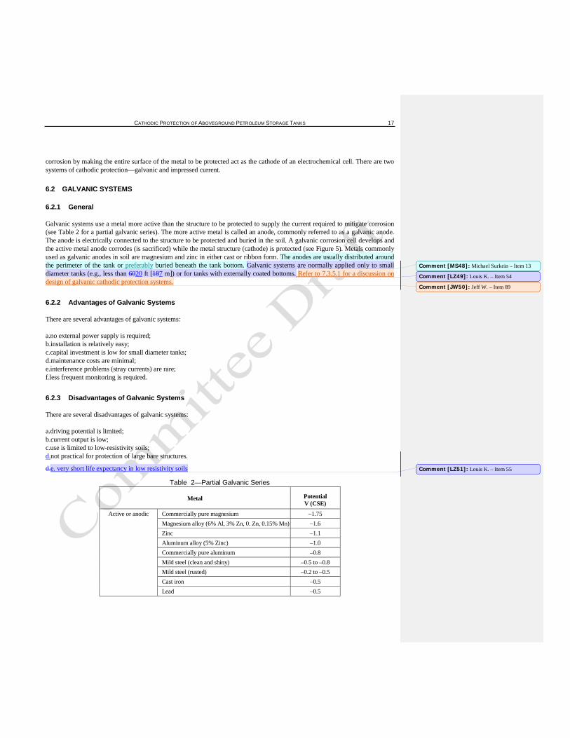
Galvanic systems use a metal more active than the structure to be protected to supply the current required to mitigate corrosion (see Table 2 for a partial galvanic series). The more active metal is called an anode, commonly referred to as a galvanic anode. The anode is electrically connected to the structure to be protected and buried in the soil. A galvanic corrosion cell develops and the active metal anode corrodes (is sacrificed) while the metal structure (cathode) is protected (see Figure 5). Metals commonly used as galvanic anodes in soil are magnesium and zinc in either cast or ribbon form. The anodes are usually distributed around the perimeter of the tank or preferably buried beneath the tank bottom. Galvanic systems are normally applied only to small diameter tanks (e.g., less than 6020 ft [187 m]) or for tanks with externally coated bottoms. Refer to 7.3.5.1 for a discussion on design of galvanic cathodic protection systems.
6.2.2 Advantages of Galvanic Systems
There are several advantages of galvanic systems:
a.no external power supply is required; b.installation is relatively easy; c.capital investment is low for small diameter tanks; d.maintenance costs are minimal; e.interference problems (stray currents) are rare; f.less frequent monitoring is required.
6.2.3 Disadvantages of Galvanic Systems
There are several disadvantages of galvanic systems:
a.driving potential is limited; b.current output is low; c.use is limited to low-resistivity soils; d.not practical for protection of large bare structures.
d.e. very short life expectancy in low resistivity soils
Table 2—Partial Galvanic Series
Metal Potential V (CSE)
Active or anodic Commercially pure magnesium –1.75 Magnesium alloy (6% Al, 3% Zn, 0. Zn, 0.15% Mn) –1.6 Zinc –1.1 Aluminum alloy (5% Zinc) –1.0 Commercially pure aluminum –0.8 Mild steel (clean and shiny) –0.5 to –0.8 Mild steel (rusted) –0.2 to –0.5 Cast iron –0.5 Lead –0.5
Comment [MS48]: Michael Surkein – Item 13
Comment [LZ49]: Louis K. – Item 54
Comment [JW50]: Jeff W. – Item 89
Comment [LZ51]: Louis K. – Item 55
18 API RECOMMENDED PRACTICE 651
Mild steel in concrete –0.2 Copper, brass, bronze –0.2 High silicon cast iron –0.2 Mill scale on steel –0.2
Noble or cathodic Carbon, graphite coke +0.3 d.
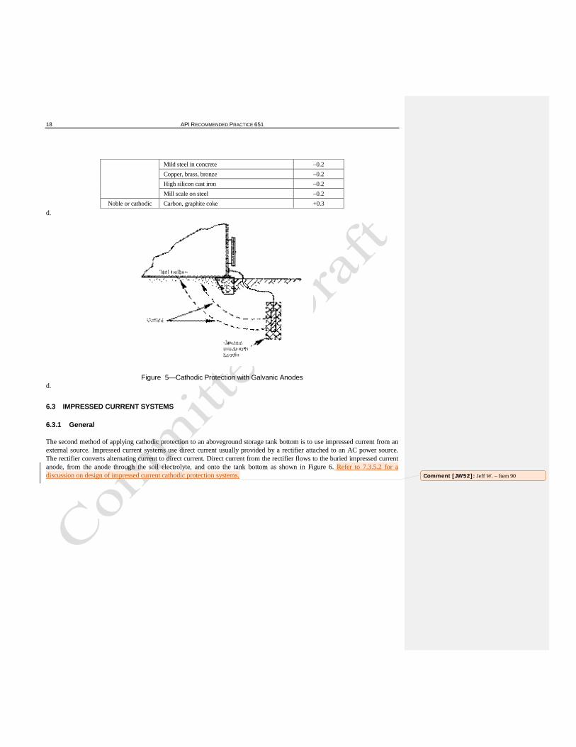
Figure 5—Cathodic Protection with Galvanic Anodes d.
6.3 IMPRESSED CURRENT SYSTEMS
6.3.1 General
The second method of applying cathodic protection to an aboveground storage tank bottom is to use impressed current from an external source. Impressed current systems use direct current usually provided by a rectifier attached to an AC power source. The rectifier converts alternating current to direct current. Direct current from the rectifier flows to the buried impressed current anode, from the anode through the soil electrolyte, and onto the tank bottom as shown in Figure 6. Refer to 7.3.5.2 for a discussion on design of impressed current cathodic protection systems. Comment [JW52]: Jeff W. – Item 90
CATHODIC PROTECTION OF ABOVEGROUND PETROLEUM STORAGE TANKS 19
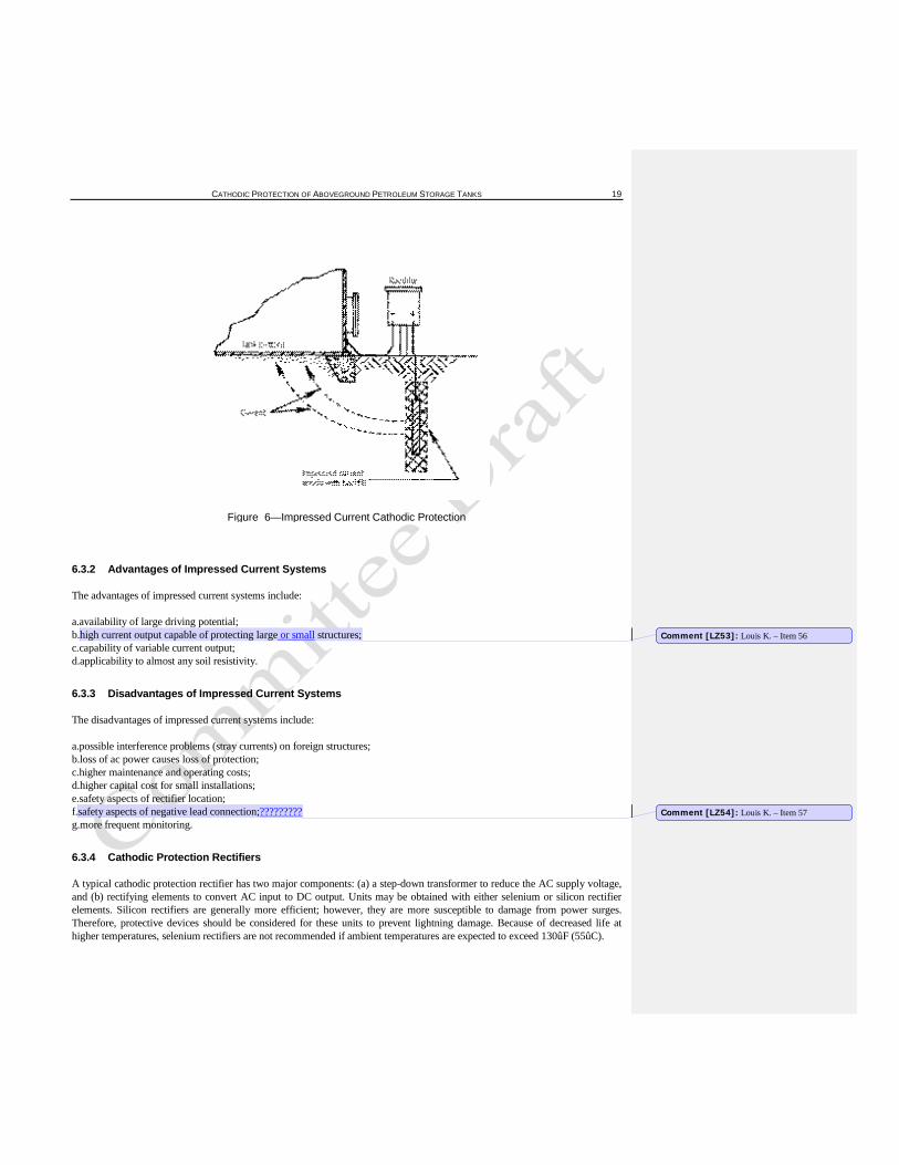
Figure 6—Impressed Current Cathodic Protection
6.3.2 Advantages of Impressed Current Systems
The advantages of impressed current systems include:
a.availability of large driving potential; b.high current output capable of protecting large or small structures; c.capability of variable current output; d.applicability to almost any soil resistivity.
6.3.3 Disadvantages of Impressed Current Systems
The disadvantages of impressed current systems include:
a.possible interference problems (stray currents) on foreign structures; b.loss of ac power causes loss of protection; c.higher maintenance and operating costs; d.higher capital cost for small installations; e.safety aspects of rectifier location; f.safety aspects of negative lead connection;????????? g.more frequent monitoring.
6.3.4 Cathodic Protection Rectifiers
A typical cathodic protection rectifier has two major components: (a) a step-down transformer to reduce the AC supply voltage, and (b) rectifying elements to convert AC input to DC output. Units may be obtained with either selenium or silicon rectifier elements. Silicon rectifiers are generally more efficient; however, they are more susceptible to damage from power surges. Therefore, protective devices should be considered for these units to prevent lightning damage. Because of decreased life at higher temperatures, selenium rectifiers are not recommended if ambient temperatures are expected to exceed 130ûF (55ûC).
Comment [LZ53]: Louis K. – Item 56
Comment [LZ54]: Louis K. – Item 57
20 API RECOMMENDED PRACTICE 651
6.3.5 Impressed Current Anodes
Impressed current anodes used in soil are made of materials such as graphite, scrap steel, high silicon cast iron, or mixed metal oxides on titanium. Anodes are usually buried in a coke breeze backfill to extend their life and reduce circuit resistance. They may be located in remote anode beds, distributed around the tank, installed underneath the tank, or installed in deep anode beds.
7 Design of Cathodic Protection Systems
7.1 INTRODUCTION
7.1.1 Cathodic protection systems are designed and installed to prevent corrosion of a tank bottom by satisfying the requirements of one or more of the criteria listed in Section 8. In order to achieve the desired results, a cathodic protection system shall be properly designed. The cathodic protection system should be designed after a study of the following items:
a.design and engineering specifications and practices (see 5.2); b.operating procedures; c.safety, environmental, and hazardous area requirements; d.field testing.
7.1.2 In general, the design should provide adequate corrosion protection while minimizing installation, maintenance, and operation costs. The major objectives of cathodic protection designs for tank bottoms are to:
a.Deliver and distribute sufficient current to the external tank bottom to ensure that the criterion for protection is met. b.Provide a design life of the anode system and other equipment commensurate with the design life of the tank or provide for periodic replacement of anodes and maintenance of equipment. c.Provide adequate allowance for anticipated changes in current requirements with time. d.Place anodes, cables, rectifiers, and test stations where the possibility of physical damage is minimal. e.Minimize interference currents on neighboring structures. f.Provide sufficient monitoring points so measurements can be taken to determine that the protection criterion is met on the entire surface of the tank bottom.
7.1.3 There are many factors for consideration in the design of both internal and external cathodic protection systems. Cathodic protection systems should be designed only by a person thoroughly familiar with cathodic protection practices on aboveground storage tanks.
7.1.4 Whenever possible, the design should be based on standard components provided by manufacturers regularly engaged in the production of cathodic protection system components for aboveground storage tanks.
7.2 INFLUENCE OF REPLACEMENT BOTTOMS, EXTERNAL LINERS (RELEASE PREVENTION BARRIERS), AND SECONDARY CONTAINMENT ON CATHODIC PROTECTION SYSTEM DESIGN
7.2.1 Barriers to Cathodic Protection
Cathodic protection is achieved by directing the flow of current from an anode to a cathode, resulting in protection of the cathode. Anything that acts as a barrier or shield to the flow of current will prevent the application of cathodic protection. RPBs and replacement bottoms can have such an effect if not properly considered.
7.2.2 Tank Bottom Replacement
Replacement of tank bottoms is an accepted practice. Whether the old bottom is left in place or removed has a significant impact on the types of cathodic protection systems that are feasible for corrosion control of the new bottom (see 7.2.4.3).
Comment [LZ55]: Louis K. – Item 58
Comment [LZ56]: Louis K. – Item 59
Comment [LZ57]: Louis K. – Item 60
Comment [LZ58]: Louis K. – Item 61
CATHODIC PROTECTION OF ABOVEGROUND PETROLEUM STORAGE TANKS 21
7.2.3 Considerations when External Liners are Used in a Diked Area
7.2.3.1 Impervious External Liner
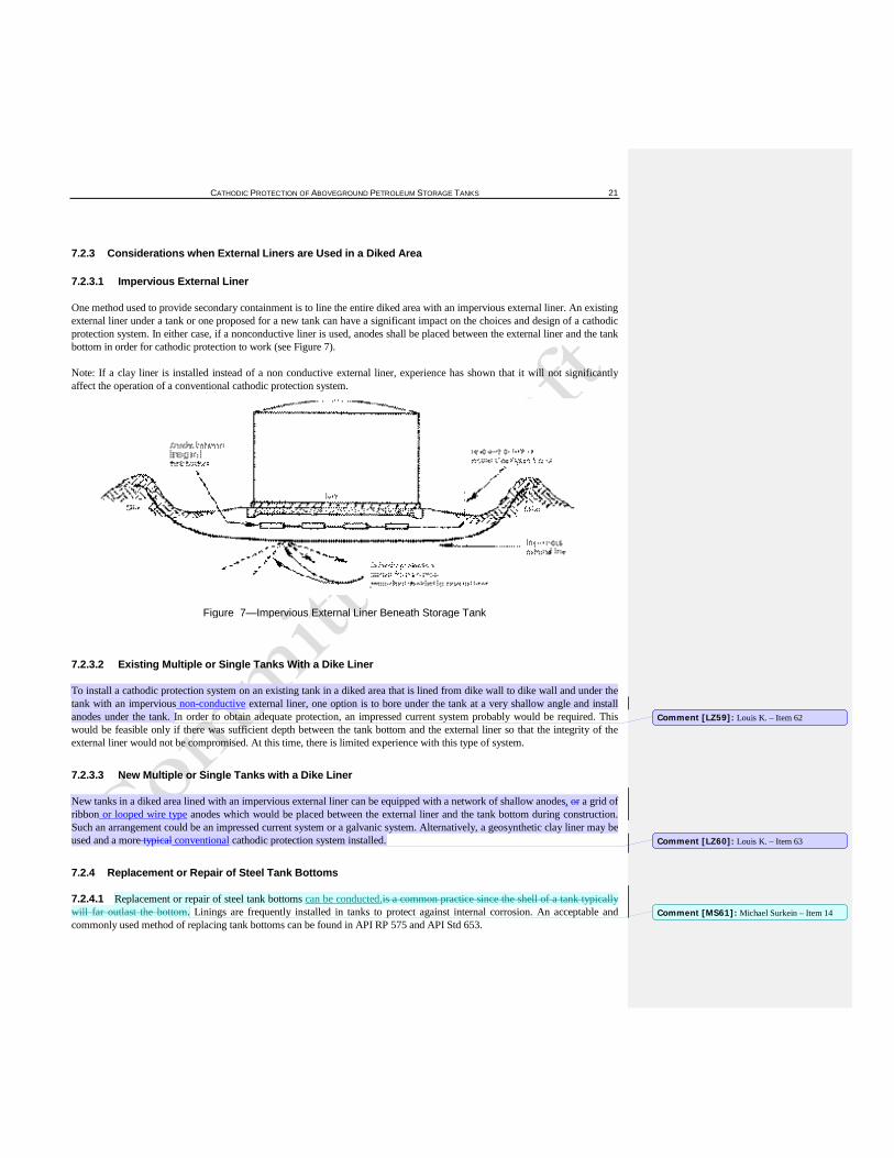
One method used to provide secondary containment is to line the entire diked area with an impervious external liner. An existing external liner under a tank or one proposed for a new tank can have a significant impact on the choices and design of a cathodic protection system. In either case, if a nonconductive liner is used, anodes shall be placed between the external liner and the tank bottom in order for cathodic protection to work (see Figure 7).
Note: If a clay liner is installed instead of a non conductive external liner, experience has shown that it will not significantly affect the operation of a conventional cathodic protection system.
Figure 7—Impervious External Liner Beneath Storage Tank
7.2.3.2 Existing Multiple or Single Tanks With a Dike Liner
To install a cathodic protection system on an existing tank in a diked area that is lined from dike wall to dike wall and under the tank with an impervious non-conductive external liner, one option is to bore under the tank at a very shallow angle and install anodes under the tank. In order to obtain adequate protection, an impressed current system probably would be required. This would be feasible only if there was sufficient depth between the tank bottom and the external liner so that the integrity of the external liner would not be compromised. At this time, there is limited experience with this type of system.
7.2.3.3 New Multiple or Single Tanks with a Dike Liner
New tanks in a diked area lined with an impervious external liner can be equipped with a network of shallow anodes, or a grid of ribbon or looped wire type anodes which would be placed between the external liner and the tank bottom during construction. Such an arrangement could be an impressed current system or a galvanic system. Alternatively, a geosynthetic clay liner may be used and a more typical conventional cathodic protection system installed.
7.2.4 Replacement or Repair of Steel Tank Bottoms
7.2.4.1 Replacement or repair of steel tank bottoms can be conducted.is a common practice since the shell of a tank typically will far outlast the bottom. Linings are frequently installed in tanks to protect against internal corrosion. An acceptable and commonly used method of replacing tank bottoms can be found in API RP 575 and API Std 653.
Comment [LZ59]: Louis K. – Item 62
Comment [LZ60]: Louis K. – Item 63
Comment [MS61]: Michael Surkein – Item 14
22 API RECOMMENDED PRACTICE 651
7.2.4.2 The method of repair or bottom replacement is of major importance in determining if cathodic protection should be installed and whether or not an effective cathodic protection system can be installed.
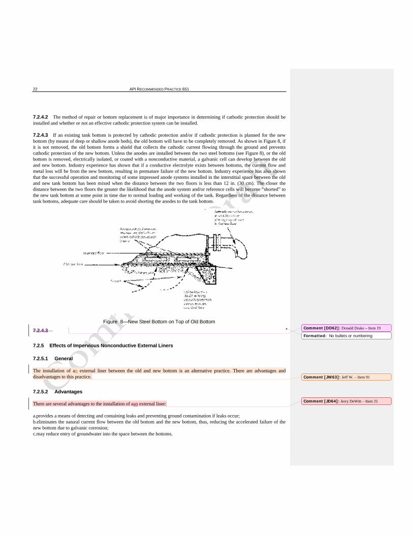
7.2.4.3 If an existing tank bottom is protected by cathodic protection and/or if cathodic protection is planned for the new bottom (by means of deep or shallow anode beds), the old bottom will have to be completely removed. As shown in Figure 8, if it is not removed, the old bottom forms a shield that collects the cathodic current flowing through the ground and prevents cathodic protection of the new bottom. Unless the anodes are installed between the two steel bottoms (see Figure 8), or the old bottom is removed, electrically isolated, or coated with a nonconductive material, a galvanic cell can develop between the old and new bottom. Industry experience has shown that if a conductive electrolyte exists between bottoms, the current flow and metal loss will be from the new bottom, resulting in premature failure of the new bottom. Industry experience has also shown that the successful operation and monitoring of some impressed anode systems installed in the interstitial space between the old and new tank bottom has been mixed when the distance between the two floors is less than 12 in. (30 cm). The closer the distance between the two floors the greater the likelihood that the anode system and/or reference cells will become “shorted” to the new tank bottom at some point in time due to normal loading and working of the tank. Regardless of the distance between tank bottoms, adequate care should be taken to avoid shorting the anodes to the tank bottom.
Figure 8—New Steel Bottom on Top of Old Bottom
7.2.4.3
7.2.5 Effects of Impervious Nonconductive External Liners
7.2.5.1 General
The installation of an external liner between the old and new bottom is an alternative practice. There are advantages and disadvantages to this practice.
7.2.5.2 Advantages
There are several advantages to the installation of aan external liner:
a.provides a means of detecting and containing leaks and preventing ground contamination if leaks occur; b.eliminates the natural current flow between the old bottom and the new bottom, thus, reducing the accelerated failure of the new bottom due to galvanic corrosion; c.may reduce entry of groundwater into the space between the bottoms.
Comment [DD62]: Donald Drake – Item 19
Formatted: No bullets or numbering
Comment [JW63]: Jeff W. – Item 91
Comment [JD64]: Jerry DeWitt – Item 25
CATHODIC PROTECTION OF ABOVEGROUND PETROLEUM STORAGE TANKS 23
7.2.5.3 Disadvantages
Installing an external liner could be disadvantageous for the following reasons:
a.an external liner makes the future addition of cathodic protection difficult; b.an external liner acts as a basin to contain water or any other electrolyte that might wet the sand between the old and new bottoms, thus, increasing corrosion rates.
7.2.5.4 Mitigation of Adverse Effects
To keep the advantages and eliminate or reduce the adverse effects of a external liner in the old bottom, install a cathodic protection system in the space between the old bottom and the new bottom. Such a system could consist of an array of ribbon or wire anodes embedded in the sand between the old bottom and the new bottom. The connecting wires project through the external liner and through a sealed bulkhead fitting (in the old shell portion) to be connected directly to the tank or through a test station. This type of system would have to be installed at the time the bottom is replaced. If unexpected anode depletion or failure occurs, remedial measures to replace anodes cannot be easily accomplished. The advantages of this system include the following:
a.the need for future cathodic protection system installation is decreased; b.the external liner acts as a barrier to current flow, protecting the old bottom and directing all the current flow toward the new bottom; c.as long as the sand stays dry and remains free of chemical contaminants, corrosion rates and current flow would be low as a result of the high resistivity of the sand; d.corrosion would tend to increase if the sand became wet; however, the resistivity of the sand would be much lower, thus, more current would flow and cathodic protection would increase (a self-governing system); e.the cost of the anodes is a small fraction of the total cost.
7.3 EXTERNAL CATHODIC PROTECTION
7.3.1 Introduction
The purpose of this section is to recommend procedures for designing cathodic protection that will effectively control external corrosion by satisfying one or more of the criteria listed in Section 8 for the intended service life of the aboveground storage tanks.
7.3.2 Design Considerations
In the design of cathodic protection, the following items should be considered:
a.Recognition of hazardous conditions existing at the proposed installation site and the selection and specification of materials and installation practices that will ensure the safe installation and operation of the cathodic protection system. b.Specification of materials and installation practices to conform with applicable codes, such as National Electrical Manufacturers Association standards, NACE recommended practices, and federal, state, and local regulations. c.Selection and design of the cathodic protection system for optimum economy of installation, maintenance, and operation. d.Selection and specification of materials and installation practices that will ensure dependable operation throughout the intended service life of the cathodic protection system. e.Selection of a design to minimize excessive protective currents or earth potential gradients that can detrimentally affect the tanks, piping, coating, or neighboring buried or submerged metallic structures. f.Provisions for monitoring the cathodic protection system operation. g.The depth of any existing tank ringwall foundation. Move to 7.3.3.1 below
Comment [LZ65]: Louis K. – Item 64
Comment [LZ66]: Louis K. – Item 65
24 API RECOMMENDED PRACTICE 651
7.3.3 Information Useful for Design
Information that is useful for design can be divided into three categories:
a.specifications and practices; b.site conditions; c.field survey, corrosion test data, and operating experience.
7.3.3.1 Specifications and Practices
Information pertaining to these specifications or practices may prove useful:
a.site plan and system layout; b.construction dates; c.tank design information; coned up bottom, coned down bottom, “w” bottom, flat bottom c. d. tank foundation design: earthen based, depth of ringwall, pilings, concrete cap/slab under tank, etc. d.pumps and power supply; e.coatings; f.corrosion control test stations; g.electrical isolation; h.electrical bonds; i.electrical conduit routing; j.electrical area classification boundaries.
7.3.3.2 Site Conditions
These factors relating to site conditions are considerations in designing cathodic protection:
a.existing and proposed cathodic protection systems; b.possible interference sources (stray current); c.special environmental conditions; d.depth of bedrock; e.depth of frost line; f.neighboring buried metallic structures (including location, ownership, and corrosion control practices); g.structure accessibility; h.power availability; i.feasibility of electrical isolation from foreign structures; j.release prevention barriers and secondary containment systems, if any; k.areas of poor water drainage.
l. depth of water table
k. m. depth of soil strata
7.3.3.3 Field Survey, Corrosion Test Data, and Operating Experience
The following information may also be useful:
a.protective current requirements to meet applicable criteria; b.electrical resistivity of the electrolyte (soil); c.electrical continuity of the system; tanks and connected piping d.electrical isolation of the system structures; e.coating integrity;
Formatted: No bullets or numbering
Comment [LZ67]: Louis K. – Item 66
Formatted: No bullets or numbering
Comment [LZ68]: Louis K. – Item 67
Comment [LZ69]: Louis K. – Item 68

CATHODIC PROTECTION OF ABOVEGROUND PETROLEUM STORAGE TANKS 25
f.leak history of similar structures in the area; g.deviation from construction specifications; h.existence of stray current; i.other maintenance and operating data.
7.3.4 Considerations that Influence Selection of the Type of Cathodic Protection System
7.3.4.1 The following factors influence the selection of a cathodic protection system:
a.size and number of tanks to be protected; b.current required; c.soil conditions such as resistivity, chemical composition, aeration, and pH; d.possibility of cathodic protection interference on adjacent structures; e.future developments and extensions to the storage system; f.cost of cathodic protection equipment, installation, operation, and maintenance; g.existing or proposed release prevention barrier and/or secondary containment system.
h. the type of liner specified
g. i. anode separation from the tank bottom
7.3.4.2 Several options are available for the protection of one or more tanks, including:
a.shallow anodes installed around the periphery of the tank; b.anodes installed directly under the tank prior to construction; c.boring at an angle or horizontally directional drilling under the tank so that anodes can be installed beneath it in a pattern that will provide adequate protection; d.use of a deep anode bed.
7.3.5 Types of Cathodic Protection Systems
7.3.5.1 Galvanic Anode System
7.3.5.1.1 Galvanic systems use galvanic anodes which can be made of materials such as magnesium or zinc in either cast or ribbon form. These are installed either bare or packaged in a special backfill. The anodes are connected to the system, either singly or in groups. Galvanic anodes are limited in current output by the system-to-anode driving voltage and the circuit resistance. It may be more economical to cathodically protect bare, poorly coated, or large structures with impressed current-type systems. Galvanic cathodic protection systems may be more economical on small diameter tanks (less than 6020 ft [187 m]; see NACE RP0193 and section 6.2 above).
7.3.5.1.2 Three galvanic anode materials are commonly used for soil installations:
a.high potential magnesium alloys; b.standard magnesium alloy; c.zinc.
7.3.5.1.3 Magnesium and zinc anodes prepackaged in special backfill are readily available in a number of size and weight configurations to meet various current output and anode life design requirements. The use of a special backfill with anodes is desirable for installation in soil environments. Special backfill, consisting of a proper mixture of gypsum, bentonite, and sodium sulfate, promotes anode efficiency, lengthens anode life, and keeps the anode environment moist.
7.3.5.1.4 The number of anodes required to provide cathodic protection for aboveground storage tanks depends upon total current requirements and the expected individual anode discharge rate in the soil. In placing the anodes, current distribution
Formatted: No bullets or numbering
Comment [JD70]: Jerry DeWitt – Item 26
Comment [LZ71]: Louis K. – Item 69
26 API RECOMMENDED PRACTICE 651
factors should also be considered. Sometimes it is advantageous to consider the use of different sizes of anodes so that more anodes will be required and give better current distribution. Typically, better current distribution and uniform polarization is obtained by distributing anodes around the tank or under the tank (for new construction).
7.3.5.2 Impressed Current System
7.3.5.2.1 Anodes
7.3.5.2.1.1 Impressed current anodes can be of materials such as, but not limited to, graphite, high silicon cast iron, scrap steel, platinized metals, magnetite, and mixed metal oxides. These anodes are installed either bare or in special backfill material (usually coke breeze). They are connected with an insulated conductor either singly or in groups to the positive terminal of a direct current source. The structure is connected to the negative terminal of the direct current source.
7.3.5.2.1.2 Graphite, high silicon cast iron, or mixed metal oxide anodes are generally preferred for soil installations. Platinized niobium, tantalum, and titanium are best suited for water rather than soil installations.
7.3.5.2.1.3 Each anode material has an optimum current density that provides maximum anode service life. Anodes may be located in remote anode beds, located in deep anode beds, or distributed closely about or under the structure to be protected. A proper anode bed design should:
a.avoid physical interference with existing facilities; b.provide uniform current distribution; and c.avoid stray current interference with offsite structures.
7.3.5.2.1.4 The number of anodes in a particular cathodic protection design will be determined by total current requirements of the structures to be protected and the optimum current density of the anode material selected. For a distributed anode design, additional anodes may be installed to provide more uniform current distribution and to provide allowance in case of isolated anode connection failures or partial anode depletion.
7.3.5.2.2 Current and Voltage Requirements
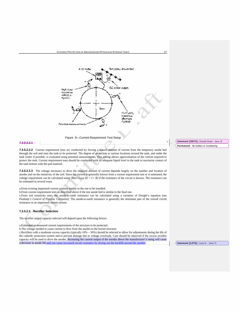
7.3.5.2.2.1 For optimum design, the current required for cathodic protection should be calculated using the results of current requirement tests. However, in lieu of a current requirement test, the generally accepted protective current density is between 1 mA/ft2 and 2 mA/ft2 at ambient temperatures (.5mA/ft2 for close coupled anodes), and current density between 2 mA/ft2 and 8 mA/ft2 for elevated temperature tanks. If a current requirement test is used, it can be performed only on existing tanks. It is conducted using a temporary anode bed and an appropriate source of direct current (see Figure 9). The temporary anode bed is typically positioned in the soil near the perimeter of the tank. Depending on the current required, the power source can vary from a 12-volt storage battery to a 300-amp welding unit.
Comment [LZ72]: Louis K. – Item 70
Comment [LZ73]: Louis K. – Item 71
CATHODIC PROTECTION OF ABOVEGROUND PETROLEUM STORAGE TANKS 27
Figure 9—Current Requirement Test Setup
7.3.5.2.2.1
7.3.5.2.2.2 Current requirement tests are conducted by forcing a known amount of current from the temporary anode bed through the soil and onto the tank to be protected. The degree of protection at various locations around the tank, and under the tank center if possible, is evaluated using potential measurements. This testing allows approximation of the current required to protect the tank. Current requirement tests should be conducted with an adequate liquid level in the tank to maximize contact of the tank bottom with the pad material.
7.3.5.2.2.3 The voltage necessary to drive the required amount of current depends largely on the number and location of anodes and on the resistivity of the soil. Since the current is generally known from a current requirement test or is estimated, the voltage requirement can be calculated using Ohm’s Law (E = I × R) if the resistance of the circuit is known. The resistance can be estimated in several ways.
a.From existing impressed current systems similar to the one to be installed. b.From current requirement tests as described above if the test anode bed is similar to the final one. c.From soil resistivity tests, the anode-to-earth resistance can be calculated using a variation of Dwight’s equation (see Peabody’s Control of Pipeline Corrosion). The anode-to-earth resistance is generally the dominant part of the overall circuit resistance in an impressed current system.
7.3.5.2.3 Rectifier Selection
The rectifier output capacity selected will depend upon the following factors.
a.Estimated or measured current requirements of the structure to be protected. b.The voltage needed to cause current to flow from the anodes to the buried structure. c.Rectifiers with a moderate excess capacity (typically 10% – 50%) should be selected to allow for adjustments during the life of the cathodic protection system and to prevent damage due to voltage overloads. Care should be observed if the excess rectifier capacity will be used to drive the anodes. Increasing the current output of the anodes above the manufacturer’s rating will cause a decrease in anode life and can cause increased circuit resistance by drying out the backfill around the anodes.
Comment [DD74]: Donald Drake – Item 19
Formatted: No bullets or numbering
Comment [LZ75]: Louis K. – Item 72
28 API RECOMMENDED PRACTICE 651
7.3.6 Electrical Isolation
7.3.6.1 Isolation devices consisting of flange assemblies, prefabricated isolating joints, or couplings should be installed where electrical isolation of the system is required to facilitate the application of corrosion control. These devices should be properly rated for temperature, pressure, and dielectric strength. Isolating devices should not be installed in enclosed areas where combustible atmospheres are normally present.
7.3.6.2 Electrical grounding of electrical equipment is an essential element in personnel safety. It may not be practical or desirable to electrically isolate storage tanks from each other or adjacent plant equipment due to the probable interconnection via a grounding grid. Attachment of auxiliary equipment such as electronic gauges, mixer motors, and lighting may also preclude the possibility of effectively maintaining isolation. When installing a cathodic protection system for a tank bottom, it should be recognized that some of the current may also be collected on adjacent buried metallic equipment. De-coupling devices should be considered when isolating electrical grounding systems from aboveground storage tanks and or piping.
7.3.6.3 Lightning arresters and fault current protection devices installed at electrical isolation locations should be of a size suitable for short term, high current loading. Where isolation devices are installed in areas of known or suspected influence from high voltage alternating current (HVAC) power lines, precautions should be taken to ensure that the AC potentials across such devices do not present a hazard to personnel. Refer to the latest revision of NACE RP0177SP0177.
7.4 INTERNAL CATHODIC PROTECTION
7.4.1 The design of an internal cathodic protection system is complicated because of the variation in the level of the accumulated corrosive medium (usually water). In addition, the presence of sludge and other contaminants could have a detrimental effect on the performance of the cathodic protection system. There are many factors which influence the design of an internal cathodic protection system. A few of these factors are as follows:
a.condition and type of coating (if any); b.minimum and maximum water level in tank; c.compatibility of stored liquid with anodes and cables; d.internal inspection interval of tank, which affects design life.
d. e. tank bottom shape: coned up, coned down, “w” type bottom, flat bottom
7.4.2 Because of the many variables associated with design of internal cathodic protection systems for petroleum storage tanks, the use of these types of systems is limited and industry wide practices do not exist. It is recommended that Sections 4 and 5 of NACE RP0575 SP0575 be consulted when designing similar systems for aboveground hydrocarbon storage tank bottoms. In addition, NACE RP0388 SP0388 should be consulted for design information for impressed current systems.
8 Criteria for Cathodic Protection
8.1 INTRODUCTION
The purpose of this section is to list criteria for cathodic protection that will indicate when adequate cathodic protection has been achieved. The selection of a particular criterion for achieving the objective depends, in part, on prior experience with similar structures and environments wherein the criterion has been used successfully.
8.2 PROTECTION CRITERIA
8.2.1 There are several criteria used to determine if adequate cathodic protection has been achieved on aboveground storage tanks. For a more detailed description, refer to the latest edition of NACE RP0193.
Comment [LZ76]: Louis K. – Item 73
Comment [DD77]: Donald Drake – Item 18
Formatted: No bullets or numbering
Comment [LZ78]: Louis K. – Item 74
Comment [DD79]: Donald Drake – Item 18
CATHODIC PROTECTION OF ABOVEGROUND PETROLEUM STORAGE TANKS 29
8.2.2 The following criteria were developed through laboratory experiments or were determined empirically by evaluating data obtained from successfully operated cathodic protection systems. It is not intended that persons responsible for corrosion control be limited to these criteria if it can be demonstrated that the control of corrosion can be achieved by other means.
8.2.2.1 A negative (cathodic) potential of at least 850 mV with the cathodic protection current applied. This potential shall be measured with respect to a saturated copper/copper sulfate reference electrode (CSE) contacting the electrolyte. Voltage drops other than those across the tank bottom-to-electrolyte boundary shall be considered for valid interpretation of this voltage measurement.
Note: “Considered” is understood to mean the application of good engineering practice in determining the significance of voltage drops by methods such as:
a.measuring or calculating the voltage drop(s), b.reviewing the historical performance of the cathodic protection system, c.evaluating the physical and electrical characteristics of the tank bottom and its environment, and d.determining whether or not there is physical evidence of corrosion.
8.2.2.2 A negative polarized potential of at least 850 mV relative to a CSE. (One common method of measuring polarized potential is by using the “instant off” technique.) This criterion may be excessive and not practical for bare steel tank bottoms.
8.2.2.3 A minimum of 100 mV of cathodic polarization measured between the tank bottom metallic surface and a stable reference electrode contacting the electrolyte. The formation or decay of this polarization can be measured to satisfy this criterion.
8.3 MEASUREMENT TECHNIQUES
8.3.1 The standard method of determining the effectiveness of cathodic protection on a tank bottom is the tank-to-soil potential measurement. These measurements are performed using a high-impedance voltmeter (greater than 10 M ohms) and a stable, reproducible reference electrode contacting the electrolyte. These measurements are commonly made with the reference electrode placed in contact with the soil at several places around the perimeter of the tank as shown in Figure 10 and, if possible, at one or more points under the tank. Undertank measurements are made because measurements at the perimeter of the tank may not represent the tank-to-soil potential of the center of the tank bottom. Methods to monitor tank-to-soil potentials under the center of the tank are discussed in 9.4. If undertank potential measurements are not used, a good engineering practice, in conjunction with the inspection and maintenance practices of API Std 653, should be used to determine that cathodic protection is adequately controlling corrosion of the tank bottom.
8.3.2 The actual structure-to-soil potential under the tank should be determined by using permanently installed reference electrodes, or by temporarily inserting a waterproof, portable reference electrode under the tank through a perforated nonmetallic tube (see 9.4). With a perforated tube, it may be possible to determine the least protected area of the tank bottom and thereafter use that one point as the primary undertank monitoring location. Permanently installed reference electrodes may vary from their original reference potential. This possible variation should be taken into account when evaluating structure-to-electrolyte potentials.
8.3.3 The tank-to-soil potential measurements may be taken with current applied; however, consideration of IR drop(s) in the soil shall be made. Consideration of the IR drop in the soil is necessary for measurements made at the tank perimeter even if the reference electrode is placed immediately adjacent to the tank. This is especially true if distributed anodes are close to the tank since the perimeter of the tank may be within the electric field gradient of the anodes.
8.3.4 The value of the IR drop and the methods of consideration should be determined by using good engineering practices. Interrupting the flow of current at the rectifiers using the “instant-off” technique is a common method. The IR drop, once determined, can be used for future tests at the same location if conditions remain similar.
Comment [LZ80]: Louis K. – Item 75
Comment [LZ81]: Louis K. – Item 76
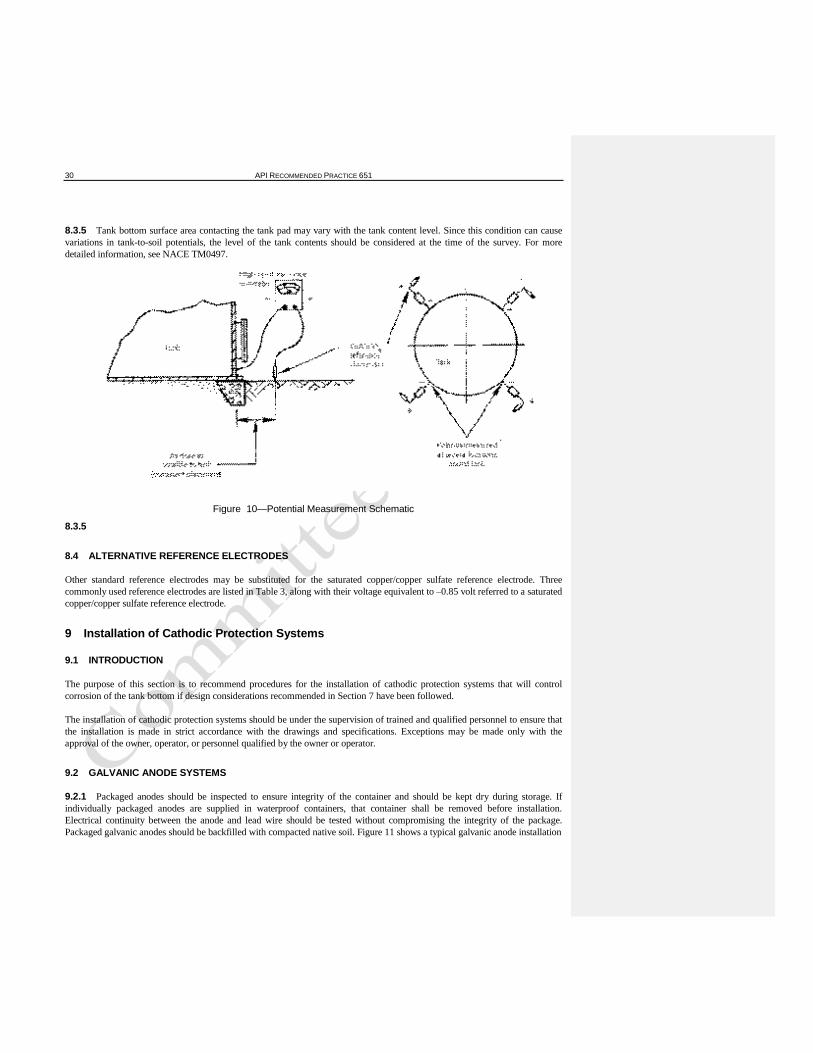
30 API RECOMMENDED PRACTICE 651
8.3.5 Tank bottom surface area contacting the tank pad may vary with the tank content level. Since this condition can cause variations in tank-to-soil potentials, the level of the tank contents should be considered at the time of the survey. For more detailed information, see NACE TM0497.
Figure 10—Potential Measurement Schematic
8.3.5
8.4 ALTERNATIVE REFERENCE ELECTRODES
Other standard reference electrodes may be substituted for the saturated copper/copper sulfate reference electrode. Three commonly used reference electrodes are listed in Table 3, along with their voltage equivalent to –0.85 volt referred to a saturated copper/copper sulfate reference electrode.
9 Installation of Cathodic Protection Systems
9.1 INTRODUCTION
The purpose of this section is to recommend procedures for the installation of cathodic protection systems that will control corrosion of the tank bottom if design considerations recommended in Section 7 have been followed.
The installation of cathodic protection systems should be under the supervision of trained and qualified personnel to ensure that the installation is made in strict accordance with the drawings and specifications. Exceptions may be made only with the approval of the owner, operator, or personnel qualified by the owner or operator.
9.2 GALVANIC ANODE SYSTEMS
9.2.1 Packaged anodes should be inspected to ensure integrity of the container and should be kept dry during storage. If individually packaged anodes are supplied in waterproof containers, that container shall be removed before installation. Electrical continuity between the anode and lead wire should be tested without compromising the integrity of the package. Packaged galvanic anodes should be backfilled with compacted native soil. Figure 11 shows a typical galvanic anode installation
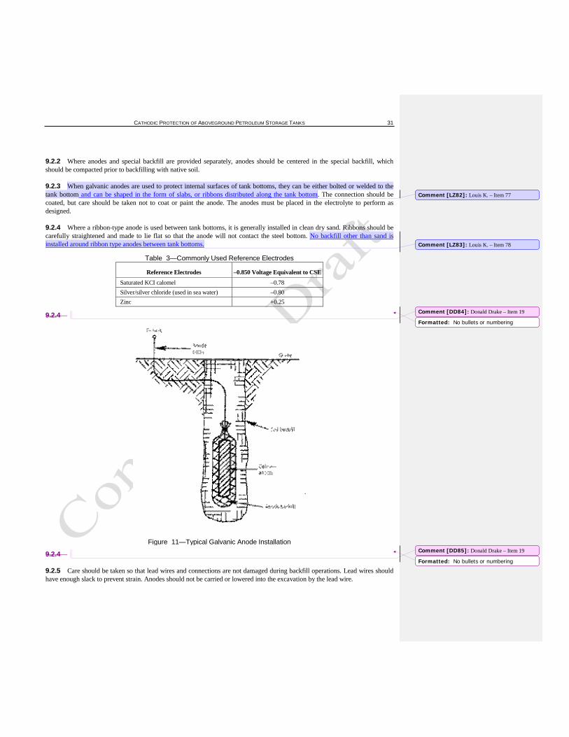
CATHODIC PROTECTION OF ABOVEGROUND PETROLEUM STORAGE TANKS 31
9.2.2 Where anodes and special backfill are provided separately, anodes should be centered in the special backfill, which should be compacted prior to backfilling with native soil.
9.2.3 When galvanic anodes are used to protect internal surfaces of tank bottoms, they can be either bolted or welded to the tank bottom and can be shaped in the form of slabs, or ribbons distributed along the tank bottom. The connection should be coated, but care should be taken not to coat or paint the anode. The anodes must be placed in the electrolyte to perform as designed.
9.2.4 Where a ribbon-type anode is used between tank bottoms, it is generally installed in clean dry sand. Ribbons should be carefully straightened and made to lie flat so that the anode will not contact the steel bottom. No backfill other than sand is installed around ribbon type anodes between tank bottoms.
Table 3—Commonly Used Reference Electrodes
Reference Electrodes –0.850 Voltage Equivalent to CSE
Saturated KCI calomel –0.78 Silver/silver chloride (used in sea water) –0.80 Zinc +0.25
9.2.4
Figure 11—Typical Galvanic Anode Installation
9.2.4
9.2.5 Care should be taken so that lead wires and connections are not damaged during backfill operations. Lead wires should have enough slack to prevent strain. Anodes should not be carried or lowered into the excavation by the lead wire.
Comment [LZ82]: Louis K. – Item 77
Comment [LZ83]: Louis K. – Item 78
Formatted: No bullets or numbering
Comment [DD84]: Donald Drake – Item 19
Formatted: No bullets or numbering
Comment [DD85]: Donald Drake – Item 19
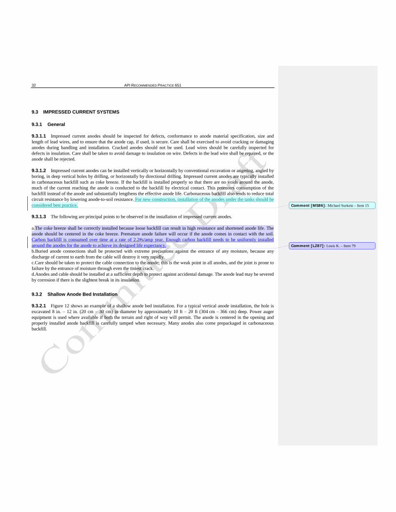
32 API RECOMMENDED PRACTICE 651
9.3 IMPRESSED CURRENT SYSTEMS
9.3.1 General
9.3.1.1 Impressed current anodes should be inspected for defects, conformance to anode material specification, size and length of lead wires, and to ensure that the anode cap, if used, is secure. Care shall be exercised to avoid cracking or damaging anodes during handling and installation. Cracked anodes should not be used. Lead wires should be carefully inspected for defects in insulation. Care shall be taken to avoid damage to insulation on wire. Defects in the lead wire shall be repaired, or the anode shall be rejected.
9.3.1.2 Impressed current anodes can be installed vertically or horizontally by conventional excavation or augering, angled by boring, in deep vertical holes by drilling, or horizontally by directional drilling. Impressed current anodes are typically installed in carbonaceous backfill such as coke breeze. If the backfill is installed properly so that there are no voids around the anode, much of the current reaching the anode is conducted to the backfill by electrical contact. This promotes consumption of the backfill instead of the anode and substantially lengthens the effective anode life. Carbonaceous backfill also tends to reduce total circuit resistance by lowering anode-to-soil resistance. For new construction, installation of the anodes under the tanks should be considered best practice.
9.3.1.3 The following are principal points to be observed in the installation of impressed current anodes.
a.The coke breeze shall be correctly installed because loose backfill can result in high resistance and shortened anode life. The anode should be centered in the coke breeze. Premature anode failure will occur if the anode comes in contact with the soil. Carbon backfill is consumed over time at a rate of 2.2#s/amp year. Enough carbon backfill needs to be uniformly installed around the anodes for the anode to achieve its designed life expectancy. b.Buried anode connections shall be protected with extreme precautions against the entrance of any moisture, because any discharge of current to earth from the cable will destroy it very rapidly. c.Care should be taken to protect the cable connection to the anode; this is the weak point in all anodes, and the joint is prone to failure by the entrance of moisture through even the tiniest crack. d.Anodes and cable should be installed at a sufficient depth to protect against accidental damage. The anode lead may be severed by corrosion if there is the slightest break in its insulation.
9.3.2 Shallow Anode Bed Installation
9.3.2.1 Figure 12 shows an example of a shallow anode bed installation. For a typical vertical anode installation, the hole is excavated 8 in. – 12 in. (20 cm – 30 cm) in diameter by approximately 10 ft – 20 ft (304 cm – 366 cm) deep. Power auger equipment is used where available if both the terrain and right of way will permit. The anode is centered in the opening and properly installed anode backfill is carefully tamped when necessary. Many anodes also come prepackaged in carbonaceous backfill.
Comment [MS86]: Michael Surkein – Item 15
Comment [LZ87]: Louis K. – Item 79
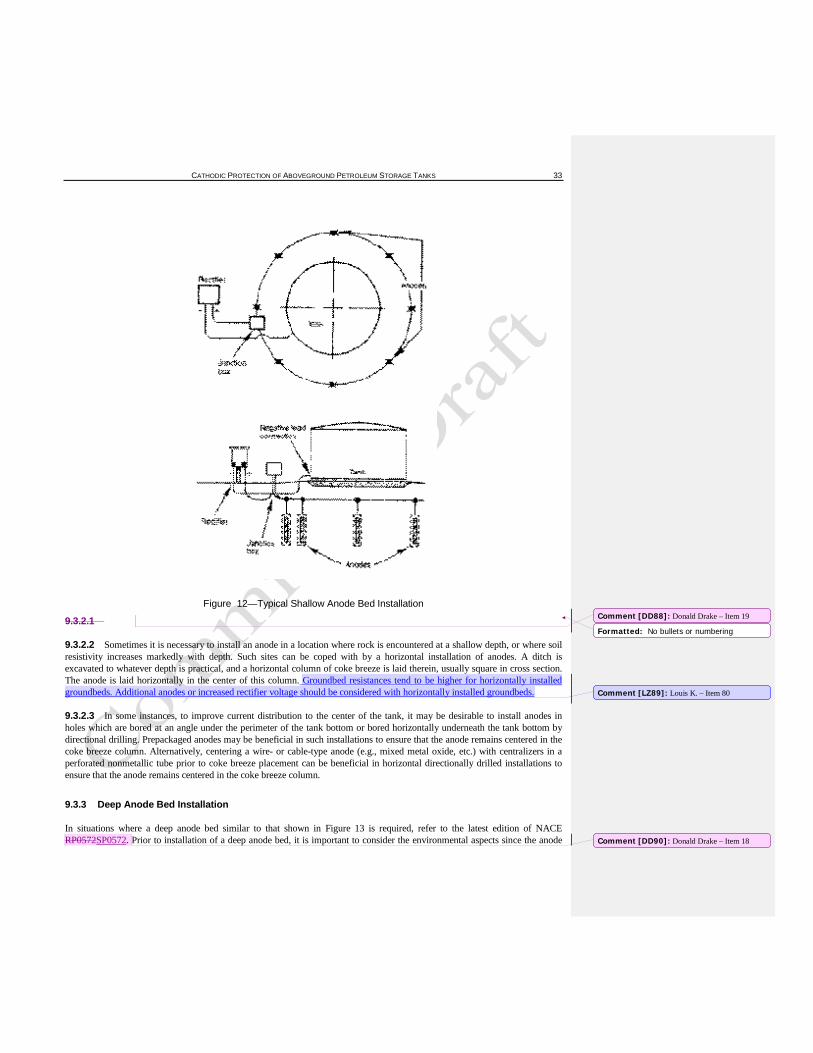
CATHODIC PROTECTION OF ABOVEGROUND PETROLEUM STORAGE TANKS 33
Figure 12—Typical Shallow Anode Bed Installation
9.3.2.1
9.3.2.2 Sometimes it is necessary to install an anode in a location where rock is encountered at a shallow depth, or where soil resistivity increases markedly with depth. Such sites can be coped with by a horizontal installation of anodes. A ditch is excavated to whatever depth is practical, and a horizontal column of coke breeze is laid therein, usually square in cross section. The anode is laid horizontally in the center of this column. Groundbed resistances tend to be higher for horizontally installed groundbeds. Additional anodes or increased rectifier voltage should be considered with horizontally installed groundbeds.
9.3.2.3 In some instances, to improve current distribution to the center of the tank, it may be desirable to install anodes in holes which are bored at an angle under the perimeter of the tank bottom or bored horizontally underneath the tank bottom by directional drilling. Prepackaged anodes may be beneficial in such installations to ensure that the anode remains centered in the coke breeze column. Alternatively, centering a wire- or cable-type anode (e.g., mixed metal oxide, etc.) with centralizers in a perforated nonmetallic tube prior to coke breeze placement can be beneficial in horizontal directionally drilled installations to ensure that the anode remains centered in the coke breeze column.
9.3.3 Deep Anode Bed Installation
In situations where a deep anode bed similar to that shown in Figure 13 is required, refer to the latest edition of NACE RP0572SP0572. Prior to installation of a deep anode bed, it is important to consider the environmental aspects since the anode
Comment [DD88]: Donald Drake – Item 19
Formatted: No bullets or numbering
Comment [LZ89]: Louis K. – Item 80
Comment [DD90]: Donald Drake – Item 18

34 API RECOMMENDED PRACTICE 651
bed may be installed through underground aquifers. It is often appropriate to provide an internal and external casing seal to maintain separation between surface and subsurface environments.
Figure 13—Commonly Installed Deep Anode Bed
9.3.4 Rectifier Installation
9.3.4.1 The rectifier or other power source should be installed so that the possibility of damage or vandalism is minimized.
9.3.4.2 Rectifiers and associated wiring should comply with local, state, and national electrical codes and electrical area classification per API RP 500. An external disconnect switch on AC wiring should be provided. The rectifier case should be properly grounded.
9.3.4.3 Lead wire connections to the rectifier shall be mechanically secure and electrically conductive. Before the power source is energized, it shall be verified that the negative lead is connected to the structure to be protected and that the positive lead is connected to the anodes.
CAUTION: If the leads are reversed, with the positive lead mistakenly attached to the tank, the tank bottom will serve as an anode and rapid corrosion failure can result.
9.3.4.4 An exothermic weld connection is the preferred means for connecting the negative rectifier lead wire to the structure to be protected; however, good mechanical connections may be substituted if necessary. All positive cable connections and wire splices should be carefully waterproofed and covered with electrical insulating material. If mechanical connections are used, they should not be buried.
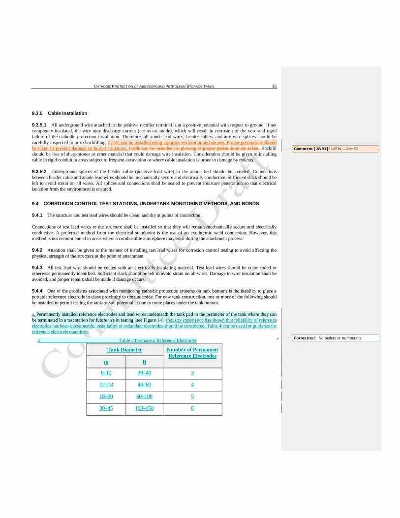
CATHODIC PROTECTION OF ABOVEGROUND PETROLEUM STORAGE TANKS 35
9.3.5 Cable Installation
9.3.5.1 All underground wire attached to the positive rectifier terminal is at a positive potential with respect to ground. If not completely insulated, the wire may discharge current (act as an anode), which will result in corrosion of the wire and rapid failure of the cathodic protection installation. Therefore, all anode lead wires, header cables, and any wire splices should be carefully inspected prior to backfilling. Cable can be installed using common excavation techniques. Proper precautions should be taken to prevent damage to buried structures. Cable can be installed by plowing if proper precautions are taken. Backfill should be free of sharp stones or other material that could damage wire insulation. Consideration should be given to installing cable in rigid conduit in areas subject to frequent excavation or where cable insulation is prone to damage by rodents.
9.3.5.2 Underground splices of the header cable (positive lead wire) to the anode bed should be avoided. Connections between header cable and anode lead wires should be mechanically secure and electrically conductive. Sufficient slack should be left to avoid strain on all wires. All splices and connections shall be sealed to prevent moisture penetration so that electrical isolation from the environment is ensured.
9.4 CORROSION CONTROL TEST STATIONS, UNDERTANK MONITORING METHODS, AND BONDS
9.4.1 The structure and test lead wires should be clean, and dry at points of connection.
Connections of test lead wires to the structure shall be installed so that they will remain mechanically secure and electrically conductive. A preferred method from the electrical standpoint is the use of an exothermic weld connection. However, this method is not recommended in areas where a combustible atmosphere may exist during the attachment process.
9.4.2 Attention shall be given to the manner of installing test lead wires for corrosion control testing to avoid affecting the physical strength of the structure at the point of attachment.
9.4.3 All test lead wire should be coated with an electrically insulating material. Test lead wires should be color coded or otherwise permanently identified. Sufficient slack should be left to avoid strain on all wires. Damage to wire insulation shall be avoided, and proper repairs shall be made if damage occurs.
9.4.4 One of the problems associated with monitoring cathodic protection systems on tank bottoms is the inability to place a portable reference electrode in close proximity to the underside. For new tank construction, one or more of the following should be installed to permit testing the tank-to-soil potential at one or more places under the tank bottom.
a. Permanently installed reference electrodes and lead wires underneath the tank pad to the perimeter of the tank where they can be terminated in a test station for future use in testing (see Figure 14). Industry experience has shown that reliability of reference electrodes has been questionable, installation of redundant electrodes should be considered. Table 4 can be used for guidance for reference electrode quantities.
a. Table 4 Permanent Reference Electrodes
Tank Diameter Number of Permanent Reference Electrodes
m ft
6–12 20–40 3
12–18 40–60 4
18–30 60–100 5
30–45 100–150 6
Comment [JW91]: Jeff W. – Item 92
Formatted: No bullets or numbering
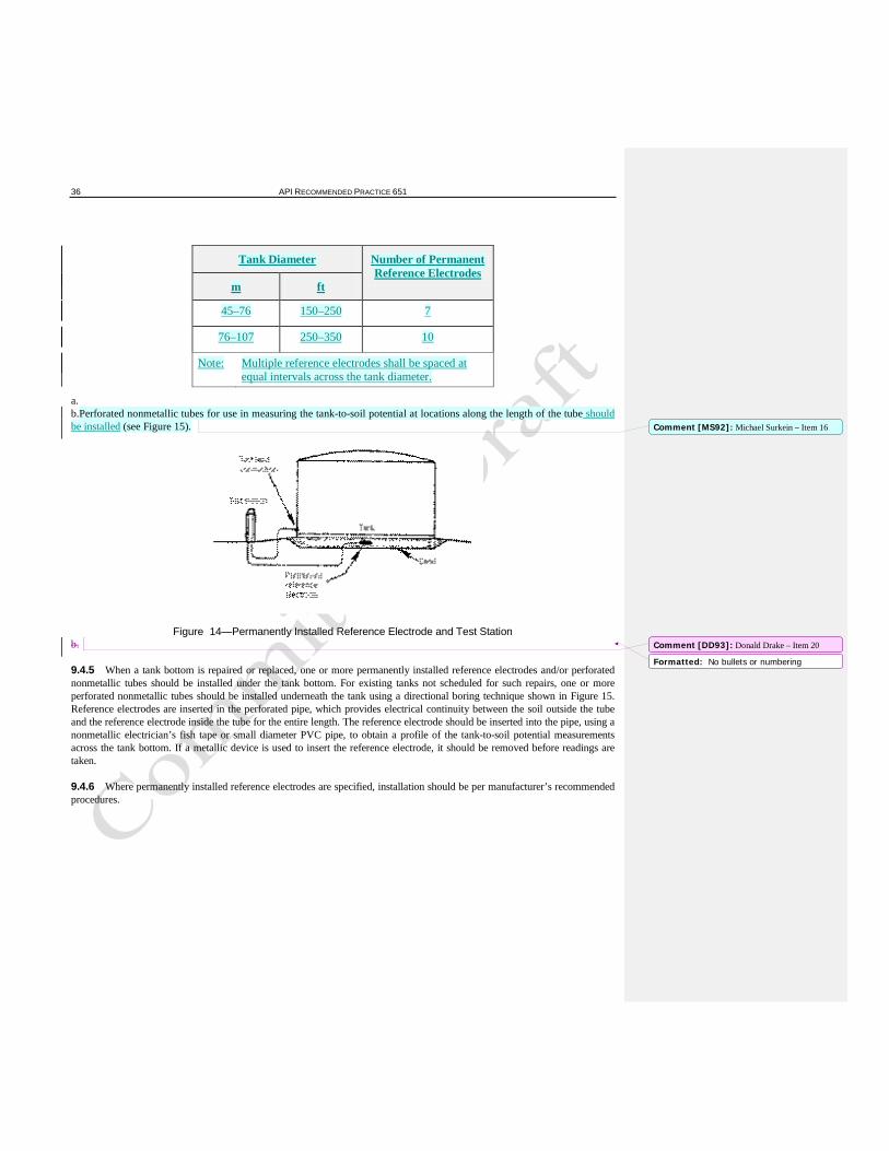
36 API RECOMMENDED PRACTICE 651
Tank Diameter Number of Permanent Reference Electrodes
m ft
45–76 150–250 7
76–107 250–350 10
Note: Multiple reference electrodes shall be spaced at equal intervals across the tank diameter.
a. b.Perforated nonmetallic tubes for use in measuring the tank-to-soil potential at locations along the length of the tube should be installed (see Figure 15).
Figure 14—Permanently Installed Reference Electrode and Test Station b.
9.4.5 When a tank bottom is repaired or replaced, one or more permanently installed reference electrodes and/or perforated nonmetallic tubes should be installed under the tank bottom. For existing tanks not scheduled for such repairs, one or more perforated nonmetallic tubes should be installed underneath the tank using a directional boring technique shown in Figure 15. Reference electrodes are inserted in the perforated pipe, which provides electrical continuity between the soil outside the tube and the reference electrode inside the tube for the entire length. The reference electrode should be inserted into the pipe, using a nonmetallic electrician’s fish tape or small diameter PVC pipe, to obtain a profile of the tank-to-soil potential measurements across the tank bottom. If a metallic device is used to insert the reference electrode, it should be removed before readings are taken.
9.4.6 Where permanently installed reference electrodes are specified, installation should be per manufacturer’s recommended procedures.
Comment [MS92]: Michael Surkein – Item 16
Comment [DD93]: Donald Drake – Item 20
Formatted: No bullets or numbering
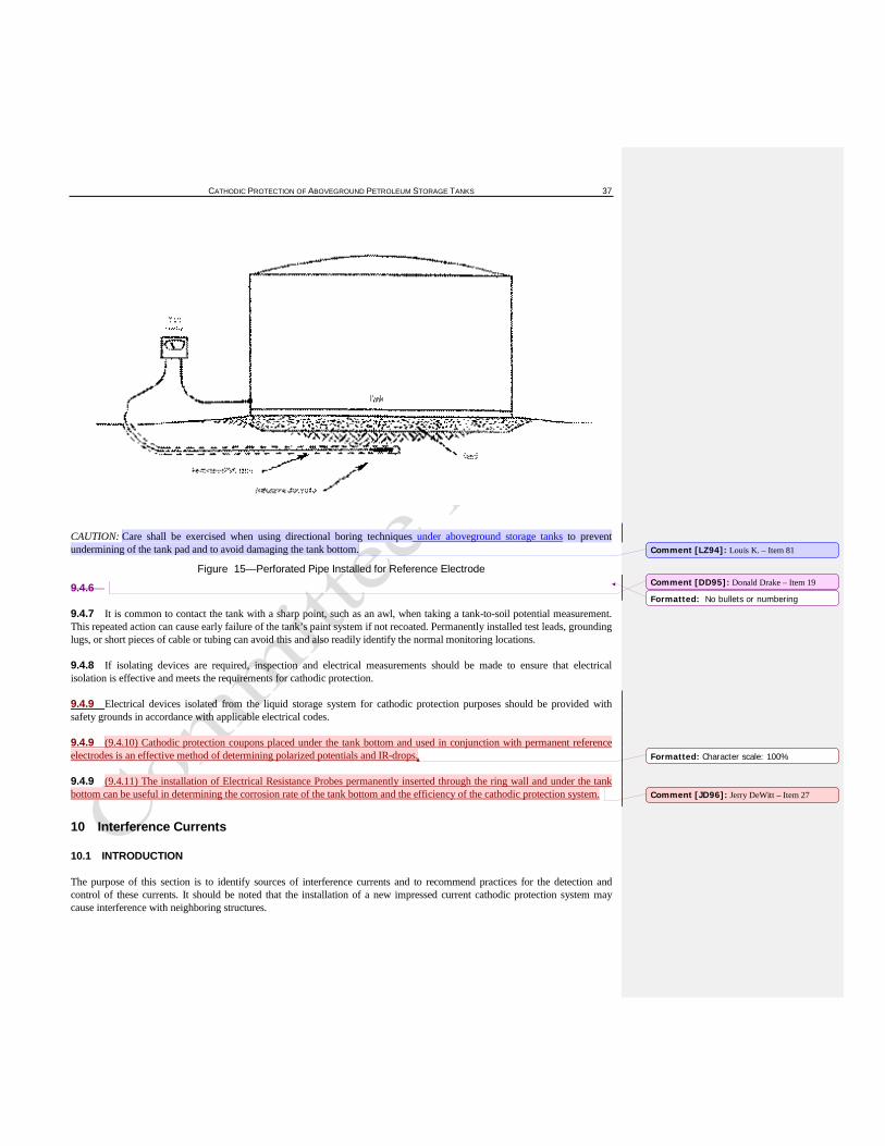
CATHODIC PROTECTION OF ABOVEGROUND PETROLEUM STORAGE TANKS 37
CAUTION: Care shall be exercised when using directional boring techniques under aboveground storage tanks to prevent undermining of the tank pad and to avoid damaging the tank bottom.
Figure 15—Perforated Pipe Installed for Reference Electrode
9.4.6
9.4.7 It is common to contact the tank with a sharp point, such as an awl, when taking a tank-to-soil potential measurement. This repeated action can cause early failure of the tank’s paint system if not recoated. Permanently installed test leads, grounding lugs, or short pieces of cable or tubing can avoid this and also readily identify the normal monitoring locations.
9.4.8 If isolating devices are required, inspection and electrical measurements should be made to ensure that electrical isolation is effective and meets the requirements for cathodic protection.
9.4.9 Electrical devices isolated from the liquid storage system for cathodic protection purposes should be provided with safety grounds in accordance with applicable electrical codes.
9.4.9 (9.4.10) Cathodic protection coupons placed under the tank bottom and used in conjunction with permanent reference electrodes is an effective method of determining polarized potentials and IR-drops.
9.4.9 (9.4.11) The installation of Electrical Resistance Probes permanently inserted through the ring wall and under the tank bottom can be useful in determining the corrosion rate of the tank bottom and the efficiency of the cathodic protection system.
10 Interference Currents
10.1 INTRODUCTION
The purpose of this section is to identify sources of interference currents and to recommend practices for the detection and control of these currents. It should be noted that the installation of a new impressed current cathodic protection system may cause interference with neighboring structures.
Comment [LZ94]: Louis K. – Item 81
Comment [DD95]: Donald Drake – Item 19
Formatted: No bullets or numbering
Formatted: Character scale: 100%
Comment [JD96]: Jerry DeWitt – Item 27
38 API RECOMMENDED PRACTICE 651
Interference is the undesirable discharge of current from a structure caused by the application of electrical current from a foreign source. Interference is normally from a DC source, although AC can also cause interference problems. A more detailed description can be found in 4.2.1. Consult the latest edition of NACE RP0193 for more information on interference currents.
10.2 SOURCES OF INTERFERENCE CURRENTS
10.2.1 Constant Current
These sources have essentially constant direct current output. The most common sources are rectifiers energizing nearby cathodic protection systems.
10.2.2 Fluctuating Current
These sources have a fluctuating direct current output. The greatest sources of stray current are the electric railway, rapid transit system, underground mining electrical systems, and welding machines.
10.3 DETECTION OF INTERFERENCE CURRENTS
During corrosion control surveys, personnel should be alert for electrical or physical observations that could indicate interference from a neighboring source. These include:
a.an electronegative shift of the historical structure-to-soil potential data on the affected structure at a point where current is picked up from the foreign direct current source, b.an electropositive shift of the historical structure-to-soil potential data on the affected structure at a point where current may be discharged from the affected structure, and c.localized pitting in areas near or immediately adjacent to a foreign structure.
Anytime a new grounbed is installed in the vicinity of other buried structures or output in increased on an existing groundbed in the vicinity of other buried structures, interference testing should be performed between all potentially affected parties.
c.
10.4 CONTROL OF INTERFERENCE CURRENTS
10.4.1 Multiple approaches may have to be employed to resolve anThere are three fundamental approaches to resolving an interference problem:
a.design that aims at minimizing exposure;
a. b. managing current output of all sources to minimize interference currents b.bonding to provide a metallic return of current collected by a foreign structurefrom the interfered with structure to the interfering structure; c.auxiliary drainage of the collected current by the use of galvanic anodes.
10.4.2 Interference problems can be prevented and resolved by participation in local corrosion coordinating committees. When interference effects are observed, the committee can often provide information on the source of the interference currents. If no local committee exists, refer to NACE TPC 11 and/or contact NACE International for information regarding these committees.
Comment [JW97]: Jeff W. – Item 93
Formatted: No bullets or numbering
Formatted: No bullets or numbering
Comment [JW98]: Jeff W. – Item 94
CATHODIC PROTECTION OF ABOVEGROUND PETROLEUM STORAGE TANKS 39
11 Operation and Maintenance of Cathodic Protection Systems
11.1 INTRODUCTION
11.1.1 The purpose of this section is to recommend procedures and practices for energizing and maintaining continuous, effective, and efficient operation of cathodic protection systems.
Electrical measurements and inspections are necessary to determine that protection has been established according to applicable criteria and that each part of the cathodic protection system is operating properly. Conditions that affect protection are subject to change with time. Corresponding changes may be required in the cathodic protection system to maintain protection. Periodic measurements and inspection are necessary to detect changes in the cathodic protection system. Conditions may exist where operating experience indicates that testing and inspections should be made more frequently than recommended herein.
11.1.2 Care should be exercised in selecting the location, number, and type of electrical measurements used to determine the adequacy of cathodic protection. If tanks are empty, there may be large areas of the bottoms which are not in contact with the underlying soil. Potential surveys, in this case, may give misleading information.
Tank bBottom-to-electrolyte potential readings may indicate adequate cathodic protection for the portion of the tank bottom in contact with the soil but when the tank is full and all of the tank bottom is in contact with the soil, protection may be insufficient. Therefore, potential surveys should be conducted with an adequate level in the tank to maximize contact of the tank bottom with the pad material.
It is good practice to mark/label the locations on aboveground storage tanks where the reference electrode is placed to ensure consistency from survey to survey.
11.1.3 If cathodic protection devices are shut off while working on storage tanks, the system should be re-energized as soon as possible to avoid corrosion damage during extensive maintenance periods.
11.2 SAFETY
11.2.1 All impressed current systems shall be designed with safety in mind. Care shall be taken to ensure that all cables are protected from physical damage and the possibility of arcing.
11.2.2 Rectifiers and junction boxes shall meet regulatory requirements for the specific location and environment in which they are installed. Such locations shall be determined by reviewing local, state, federal, and prevailing industrial codes.
Consideration should be given to locating isolating devices, junction boxes, and rectifiers outside of hazardous areas in case sparks or arcs occur during testing.
11.2.3 In order to prevent arcing, care shall be exercised when working on breakout piping attached to tanks with cathodic protection applied. When cathodic protection systems are turned off, sufficient time shall be allowed for depolarization before opening connections. Bonding cables shall be used when parting breakout piping joints. Additional guidance regarding arcing due to static electricity, stray currents or lightening can be obtained from API RP 2003.
11.3 CATHODIC PROTECTION SURVEYS
11.3.1 General
11.3.1.1 Prior to energizing a new cathodic protection system, measurements of the native structure-to-soil potential should be made. Immediately after any cathodic protection system is energized or repaired, a survey should be conducted to determine that it operates properly. An initial survey to verify that it satisfies applicable criteria should be conducted after adequate polarization
Comment [LZ99]: Louis K. – Item 82
40 API RECOMMENDED PRACTICE 651
has occurred. Polarization to a steady state may take several months after the system is energized. This survey should include one or more of the following types of measurements:
a.polarized structure-to-soil potential; b.anode current; c.native structure-to-soil potentials; d.structure-to-structure potential; e.piping-to-tank isolation if protected separately; f.structure-to-soil potential on adjacent structures; g.continuity of structures if protected as a single structure; h.rectifier DC volts, DC amps, efficiency, and tap settings.
11.3.1.2 Annual cathodic protection surveys are recommended to ensure the effectiveness of cathodic protection. The electrical measurements used in the survey may include one or more of the measurements listed in 11.3.1.1.
11.3.2 Inspection, Testing, and Maintenance of Cathodic Protection Facilities
11.3.2.1 Inspection and tests of cathodic protection facilities should be made to ensure their proper operation and maintenance.
11.3.2.2 All sources of impressed current should be checked at intervals not exceeding two months unless specified otherwise by regulation. Evidence of proper function may be current output, normal power consumption, a signal indicating normal operation, or satisfactory electrical state of the protected structure. A satisfactory comparison between the rectifier operation on a bimonthly basis and the rectifier operation during the annual survey implies the protected status of affected structures is similar. This does not take into account possible effects of foreign current sources.
11.3.2.3 All impressed current protective facilities should be inspected annually as part of a preventive maintenance program to minimize in-service failure. Inspections should include a check of the general condition, including electrical shorts, ground connections, rectifier meter accuracy, efficiency, and circuit resistance.
11.3.2.4 The effectiveness of isolating devices and continuity bonds should be evaluated during the periodic surveys. This can be accomplished by onsite inspection or by evaluating cathodic protection test data.
11.3.2.5 The tank bottom should be examined for evidence of corrosion whenever access to the bottom is possible. This may be during repairs or modifications, or in conjunction with inspections required by API Std 653. Examination for bottom-side corrosion may be achieved by making coupon cutouts or by nondestructive methods such as ultrasonic inspections or electromagnetic flux leakage.
11.3.2.6 Remedial measures should be taken where periodic tests and inspections indicate that protection is no longer adequate according to applicable criteria. These measures may include the following:
a.repair, replacement, or adjustment of cathodic protection system components; b.providing supplementary cathodic protection where additional protection is necessary; c.repair, replacement, or adjustment of continuity and interference bonds; d.elimination of accidental metallic contacts; e.repair of defective isolation devices; f.resolution of interference currents.
11.4 CATHODIC PROTECTION RECORDS
11.4.1 Data pertinent to the design, installation, operation, maintenance, and effectiveness of corrosion control measures should be documented in a clear, concise, and workable manner.
Comment [JW100]: Jeff W. – Item 95
CATHODIC PROTECTION OF ABOVEGROUND PETROLEUM STORAGE TANKS 41
11.4.2 In determining of the need for cathodic protection, items listed in 5.2 should be recorded.
11.4.3 In designing cathodic protection systems, the following should be recorded:
a.design and location of isolating devices, test leads and other test facilities, and details of other special corrosion control measures taken; b.results of current requirement tests, where made, and procedures used; c.native structure-to-soil potentials before current is applied; d.results of soil resistivity tests at the site, where they were made, and procedures used; e.name of person conducting surveys.
11.4.4 In installing corrosion control facilities, the following should be recorded.
a.Impressed current systems. 1. location and date placed in service; 2. number, type, size, depth, backfill, and spacing of anodes; 3. specifications of rectifier or other energy source; 4. interference tests and the parties participating in resolution of any interference problems.
b.Galvanic anode systems. 1. location and date placed in service; 2. number, type, size, depth, backfill, and spacing of anodes unless part of a factory installed system.
11.4.5 A record of surveys, inspections, and tests described in 11.3.1 and 11.3.2 should be maintained to demonstrate that applicable criteria for cathodic protection have been satisfied.
11.4.6 In maintaining corrosion control facilities, the following information should be recorded:
a.repair of rectifiers and other dc power sources; b.repair or replacement of anodes, connections, and cable; c.maintenance, repair, and replacement of coating, isolating devices, test leads, and other test facilities.
11.4.7 Records sufficient to demonstrate the need for corrosion control measures should be retained as long as the facility involved remains in service. Records related to the effectiveness of cathodic protection should be retained for a period of five years unless a shorter period is specifically allowed by regulation.
FOREWORD
Nothing contained in any API publication is to be construed as granting any right, by implication or otherwise, for the manufacture, sale, or use of any method, apparatus, or product covered by letters patent. Neither should anything contained in the publication be construed as insuring anyone against liability for infringement of letters patent.
This document was produced under API standardization procedures that ensure appropriate notification and participation in the developmental process and is designated as an API standard. Questions concerning the interpretation of the content of this publication or comments and questions concerning the procedures under which this publication was developed should be directed in writing to the Director of Standards, American Petroleum Institute, 1220 L Street, N.W., Washington, D.C. 20005. Requests for permission to reproduce or translate all or any part of the material published herein should also be addressed to the director.
Generally, API standards are reviewed and revised, reaffirmed, or withdrawn at least every five years. A one-time extension of up to two years may be added to this review cycle. Status of the publication can be ascertained from the API Standards Department, telephone (202) 682-8000. A catalog of API publications and materials is published annually and updated quarterly by API, 1220 L Street, N.W., Washington, D.C. 20005.
42 API RECOMMENDED PRACTICE 651
Suggested revisions are invited and should be submitted to the Standards and Publications Department, API, 1220 L Street, NW, Washington, D.C. 20005, [email protected].
Persons planning to construct an aboveground storage facility, replace existing aboveground storage tanks and associated piping systems, or cathodically protect existing aboveground storage tanks and associated piping should refer to applicable local, state, and federal fire, safety, and environmental regulations as well as the most recent edition of the following publications:
a.API Std 650; b.API RP 652; c.API Std 653; d.API Spec 12B; e.API Spec 12D; f.API Spec 12F; g.API Std 2610; h.NACE RP0193; i.NACE RP0285; j.NFPA 30; k.NFPA 70; and, l.PEI RP200.
The appropriate government authority having jurisdiction should be consulted for regulations that apply to the area of installation prior to taking any action suggested in this recommended practice.
iii
1 SCOPE ........................................................................................................................
2 REFERENCES ............................................................................................................
1
2.1 Standards, Codes, Publications, and Specifications ............................................. 1 1
2.2 Other References ................................................................................................ 2
3 DEFINITIONS ............................................................................................................
4 CORROSION OF ABOVEGROUND STEEL STORAGE TANKS ...........................
2
4.1 Introduction ........................................................................................................ 5 5
4.2 Corrosion Mechanisms ....................................................................................... 6 4.3 Internal Corrosion ............................................................................................... 7
5 DETERMINATION OF NEED FOR CATHODIC PROTECTION ............................ 5.1 Introduction ........................................................................................................ 8
8
5.2 Tank History ...................................................................................................... 9 5.3 Tank Pad and Soil Conditions........................................................................... 10 5.4 Other Factors Affecting Cathodic Protection .................................................... 13
6 METHODS OF CATHODIC PROTECTION FOR CORROSION CONTROL ........ 6.1 Introduction ...................................................................................................... 14
14
6.2 Galvanic Systems ............................................................................................. 14 6.3 Impressed Current Systems .............................................................................. 15
7 DESIGN OF CATHODIC PROTECTION SYSTEMS ............................................. 7.1 Introduction ...................................................................................................... 16
16
7.2 Influence of Replacement Bottoms, External Liners (Release Prevention ..... Barriers), and Secondary Containment on Cathodic Protection System Design 17
7.3 External Cathodic Protection ............................................................................ 19
CATHODIC PROTECTION OF ABOVEGROUND PETROLEUM STORAGE TANKS 43
7.4 Internal Cathodic Protection ............................................................................. 23
8 CRITERIA FOR CATHODIC PROTECTION .......................................................... 8.1 Introduction ...................................................................................................... 23
23
8.2 Protection Criteria ............................................................................................ 23 8.3 Measurement Techniques ................................................................................. 24 8.4 Alternative Reference Electrodes ...................................................................... 24
9 INSTALLATION OF CATHODIC PROTECTION SYSTEMS ............................... 9.1 Introduction ...................................................................................................... 25
25
9.2 Galvanic Anode Systems .................................................................................. 25 9.3 Impressed Current Systems .............................................................................. 26 9.4 Corrosion Control Test Stations, Undertank Monitoring Methods, and Bonds .. 29
10 INTERFERENCE CURRENTS ................................................................................ 10.1 Introduction ...................................................................................................... 30
30
10.2 Sources of Interference Currents ....................................................................... 31 10.3 Detection of Interference Currents .................................................................... 31 10.4 Control of Interference Currents ....................................................................... 31
11 OPERATION AND MAINTENANCE OF CATHODIC PROTECTION ...................................................................................................................... SYSTEMS 11.1 Introduction ...................................................................................................... 31
31
11.2 Safety ............................................................................................................... 32 11.3 Cathodic Protection Surveys ............................................................................. 32 11.4 Cathodic Protection Records ............................................................................ 33
Figures 1 Electrochemical Corrosion Cell .............................................................................. 5 2 Oxygen Concentration Cell Caused by Rocks or Clay in Tank Pad ........................ 6 3 Example of Stray Current Corrosion of an Unprotected Tank Bottom .................... 7 4 Galvanic Corrosion ................................................................................................ 7 5 Cathodic Protection with Galvanic Anodes .......................................................... 15 6 Impressed Current Cathodic Protection ................................................................ 15 7 Impervious External Liner Beneath Storage Tank ................................................ 17 8 New Steel Bottom on Top of Old Bottom ............................................................ 18 9 Current Requirement Test Setup .......................................................................... 22 10 Potential Measurement Schematic ........................................................................ 25 11 Typical Galvanic Anode Installation .................................................................... 26 12 Typical Shallow Anode Bed Installation .............................................................. 27 13 Commonly Installed Deep Anode Bed ................................................................. 28 14 Permanently Installed Reference Electrode and Test Station ................................ 29 15 Perforated Pipe Installed for Reference Electrode ................................................ 30
Tables
1 General Classification of Resistivity .................................................................... 10 2 Partial Galvanic Series ......................................................................................... 14 3 Commonly Used Reference Electrodes ................................................................ 25
v 01/07
Product No. C65103 Comment [JL101]: John Lieb – item 1