cathode design for proton exchange membrane fuel cells in
TRANSCRIPT
University of Birmingham
Cathode design for proton exchange membrane fuelcells in automotive applicationsWang, Haojie; Wang, Ruiqing; Sui, Sheng; Sun, Tai; Yan, Yichang; Du, Shangfeng
DOI:10.1007/s42154-021-00148-y
License:Creative Commons: Attribution (CC BY)
Document VersionPublisher's PDF, also known as Version of record
Citation for published version (Harvard):Wang, H, Wang, R, Sui, S, Sun, T, Yan, Y & Du, S 2021, 'Cathode design for proton exchange membrane fuelcells in automotive applications', Automotive Innovation, vol. 4, no. 2, pp. 144-164.https://doi.org/10.1007/s42154-021-00148-y
Link to publication on Research at Birmingham portal
General rightsUnless a licence is specified above, all rights (including copyright and moral rights) in this document are retained by the authors and/or thecopyright holders. The express permission of the copyright holder must be obtained for any use of this material other than for purposespermitted by law.
•Users may freely distribute the URL that is used to identify this publication.•Users may download and/or print one copy of the publication from the University of Birmingham research portal for the purpose of privatestudy or non-commercial research.•User may use extracts from the document in line with the concept of ‘fair dealing’ under the Copyright, Designs and Patents Act 1988 (?)•Users may not further distribute the material nor use it for the purposes of commercial gain.
Where a licence is displayed above, please note the terms and conditions of the licence govern your use of this document.
When citing, please reference the published version.
Take down policyWhile the University of Birmingham exercises care and attention in making items available there are rare occasions when an item has beenuploaded in error or has been deemed to be commercially or otherwise sensitive.
If you believe that this is the case for this document, please contact [email protected] providing details and we will remove access tothe work immediately and investigate.
Download date: 26. Dec. 2021

Vol.:(0123456789)1 3
Automotive Innovation https://doi.org/10.1007/s42154-021-00148-y
Cathode Design for Proton Exchange Membrane Fuel Cells in Automotive Applications
Haojie Wang1 · Ruiqing Wang2 · Sheng Sui2 · Tai Sun3 · Yichang Yan4 · Shangfeng Du4
Received: 21 November 2020 / Accepted: 22 March 2021 © The Author(s) 2021
AbstractAn advanced cathode design can improve the power performance and durability of proton exchange membrane fuel cells (PEMFCs), thus reducing the stack cost of fuel cell vehicles (FCVs). Recent studies on highly active Pt alloy catalysts, short-side-chain polyfluorinated sulfonic acid (PFSA) ionomer and 3D-ordered electrodes have imparted PEMFCs with boosted power density. To achieve the compacted stack target of 6 kW/L or above for the wide commercialization of FCVs, developing available cathodes for high-power-density operation is critical for the PEMFC. However, current developments still remain extremely challenging with respect to highly active and stable catalysts in practical operation, controlled distribution of ionomer on the catalyst surface for reducing catalyst poisoning and oxygen penetration losses and 3D (three-dimensional)-ordered catalyst layers with low Knudsen diffusion losses of oxygen molecular. This review paper focuses on impacts of the cathode development on automotive fuel cell systems and concludes design directions to provide the greatest benefit.
Keywords Fuel cell vehicle (FCV) · Proton exchange membrane fuel cell (PEMFC) · Cathode · Mass transport · Ionomer
AbbreviationsCCL Cathode catalyst layerCL Catalyst layerCNT Carbon nanotubeECSA Electrochemical surface areaEW Equivalent weightFCV Fuel cell vehicleGDE Gas diffusion electrodeGDL Gas diffusion layerLSC Long-side chainMEA Membrane electrode assemblyMPL Microporous layer
ORR Oxygen reduction reactionPBI PolybenzimidazolePEG Polyethylene glycolPEM Proton exchange membranePEMFC Proton exchange membrane fuel cellPFSA Polyfluorinated sulfonic acidPGM Platinum group metalPTFE PolytetrafluoroethyleneRDE Rotating disk electrodeTPB Triple-phase boundary
1 Introduction
Fuel cells convert chemical energy from the reaction of a fuel (hydrogen or hydrocarbons) and an oxidant (i.e., oxy-gen) directly into electricity with high efficiency and envi-ronmental benefits (zero or low emission). The fuel cell technology has been successfully used in many applica-tions, such as stationary power generation for electricity grid, automobile vehicles and portable power devices [1]. Among all types of fuel cells, PEMFC is one of the most promising alternatives to internal combustion engines (ICEs) as power sources for transportation because PEMFCs oper-ate at close to ambient conditions, enabling fast start-up and shut-down [2]. Since the first use for the Gemini spacecraft
* Sheng Sui [email protected]
* Shangfeng Du [email protected]
1 School of Mechanical and Power Engineering, East China University of Science and Technology, Shanghai 200237, China
2 Institute of Fuel Cells, Shanghai Jiao Tong University, Shanghai 200240, China
3 Research Institute of Rare Metals, Guangdong Academy of Sciences, Guangzhou 510650, Guangdong, China
4 School of Chemical Engineering, University of Birmingham, Birmingham B15 2TT, UK

H. Wang et al.
1 3
by General Electric (GE) in the 1960s, the PEMFC tech-nology goes through a long way to access commercializa-tion [3]. Japan, South Korea, the US, European nations and China have successively formulated visions and roadmaps of hydrogen and fuel cells, and lead commercialization of fuel cell electric vehicles (FCVs). Toyota launched the first-generation commercial FCV MIRAI in 2014 and the second copy in 2019. Hyundai also revealed their new hydrogen fuel cell SUV Nexo in 2018. However, to compete with ICE vehicles, PEMFCs in FCVs are challenging in the fields of cost reduction and performance improvement, particularly in the ability to achieve high-power-density operation at high energy efficiency [4].
Figure 1 shows the schematic representation of a PEMFC. The core of the PEMFC is a membrane electrode assem-bly (MEA), which includes the polymer electrolyte mem-brane (PEM), catalyst layers (CLs) and gas diffusion layers (GDLs). The MEA is the place for electrochemical reactions including hydrogen oxidation reaction (HOR) at the anode and oxygen reduction reaction (ORR) at the cathode, and also for transfer processes involving multiphase transport, i.e., fuel and oxidant gases from GDLs to CLs, the proton from the anode to the cathode through the PEM and trans-port of water produced in the cathode [5]. Many studies on PEMFCs for vehicle applications now focus on the R&D of cost-effective MEAs with low platinum loading and high durability under practical operating conditions [6, 7].
In PEMFCs, the sluggish ORR at the cathode is about 5–6 magnitudes slower than the hydrogen oxidation reac-tion HOR at the anode, thus causing a large kinetic loss that limits the fuel cell power performance. Therefore, more catalysts are required for the cathode than that for the anode to boost the ORR rate during fuel cell operation. Pt is com-monly used at both electrodes and it alone is accountable for more than 40% of the MEA cost in PEMFCs, delaying mass commercialization of this technology. Lots of efforts have been made to improve the catalyst activity and reduce the Pt loading [3]. The first PEMFC unit used in the Gemini
aircraft contained a very high catalyst loading (4 mgPt/cm2) of unsupported Pt black bound by polytetrafluoroethylene (PTFE) within the electrodes [9]. An important break-through in the PEMFC development was achieved by Los Alamos National Laboratory in the 1980s, when the cata-lyst utilization was significantly improved and the Pt loading was reduced to less than 0.4 mg/cm2 as mostly used today. Those were achieved through extending the triple-phase boundary (TPB) zone in the catalyst layer by introducing proton-conducting ionomer (such as Nafion) and the car-bon-supported platinum (Pt/C) catalyst into the electrodes. Since then, further progresses have been achieved on the improvement of MEAs and the related technologies [10]. For example, Chong et al. [11] prepared highly active ORR catalysts by growing PtCo alloy nanoparticles on CoNC substrate derived from zeolitic imidazolate frameworks. With an ultralow cathode Pt loading of 0.033 mgPt/cm2, the MEA achieved a power density of more than 1 W/cm2 in H2-air fuel cell test under 2 barabs of absolute pressure. With N-modified carbon as support for Pt nanoparticle catalysts, Ott et al. [12] designed cathodes showing a power density of 1.39 W/cm2 at a cathode Pt loading of 0.11 mgPt/cm2 (tested at 80 °C with fully humidified H2/air at a pressure of 230 kPaabs).
Despite tremendous progress achieved with the PEMFC development, there are still many challenges with PEMFCs for their extensive commercialization as FCVs, especially related to the exorbitant cost, low-power performance and poor durability. The cost of an FCV mainly comes from manufacturing and materials. Manufacturing issues, a big part contributing to the current high fuel cell system cost, are amenable to major reduction through economies of scale. Whereas precious metal material costs with the electrocata-lysts would not benefit from the economy of scale and even increases at high FCV market penetration [5]. A potential strategy to address this challenge is the development of high-power-performance electrodes with an ultralow Pt loading or Pt-free through the novel catalyst and electrode structure design. Another problem is, along with the development of PEMFCs operating at a large current density (e.g. > 2.5 A/cm2), the cathode catalyst layer undergoes a high water sat-uration level (i.e., flooding conditions). This thus reduces oxygen mass transport to reaction sites of the catalyst finally resulting in poor fuel cell power performance [13]. Accord-ingly, various technologies, including 3D mesh flow field plates [14, 15], ordered structure electrodes [16] and hydro-phobic GDLs [17], have been investigated to overcome the water management issues.
In this review paper, an overview of the R&D of PEM-FCs with a focus on the cathode catalyst layer is first pre-sented, according to a viewpoint from micro-scale TPB to macro-scale catalyst layer design. Then, research advance-ments about promoting intrinsic cathodic ORR activities
Fig. 1 Flux balance overviews in a simplified PEMFC model [8]

Cathode Design for Proton Exchange Membrane Fuel Cells in Automotive Applications
1 3
in PEMFCs are briefly described. The research efforts on improving mass transport of oxygen and water in the cathode catalyst layer are discussed in detail. Publications reporting MEAs with high-power-density operation are also reviewed. At last, an outlook of the catalyst electrode development for high-power-density operation PEMFCs is given.
2 Promoting Intrinsic Kinetic Performance of Electrodes
2.1 Triple‑Phase Boundary (TPB)
The catalyst layer in fuel cell operation provides continu-ous channels for electrochemical reactants including pro-tons, electrons and gas (and water in the cathode) [18, 19]. As shown in Fig. 2, the interface (red hollow circle)among the catalyst for conducting electrons, electrolyte phase for conducting protons and pores for transporting gases and/or water is named as TPB. This concept has been generally used in the study of electrode structure to explain the com-plex interaction within the CL [20, 21].
The electrochemical reaction within the CL is multiphase. Typically, the catalyst layer is a thin film composed of car-bon-supported highly dispersed Pt catalyst nanoparticles and Nafion ionomer additive [22]. The microstructure and composition of the CL have a great influence on its power performance [20, 23–26]. Therefore, many research efforts have been made to optimize the TPB properties within the CL, which can be divided into three strategies: (i) adopting highly active catalysts to promote the intrinsic ORR activ-ity, (ii) introducing novel ionomers to enhance conductivity and (iii) improving catalyst/ionomer interface to extend TPB zones [27, 28].
2.2 ORR Catalysts
To create efficient triple-phase interfaces to catalyze the ORR, highly active catalysts are essential. In view of the elements, the catalysts are usually divided into two catego-ries as platinum group metal (PGM) and platinum group metal-free (PGM-free)-based materials. Among all the exploited catalysts, pure Pt or Pt-based catalysts are still the best option in terms of automotive applications. The pro-gress and achievements of ORR catalysts in recent decades have been frequently reviewed by researchers based on their activities and durability [3, 29, 30].
2.2.1 Pt‑based Catalysts
Pt-based catalysts, including pure platinum, platinum alloys and core–shell platinum structures, are the dominant choices for ORR [31–33]. For single-crystal Pt catalysts, controlling
facets via surface atom rearrangement can tune their cata-lytic activities [34] because of the structure sensitivity of the ORR to different Pt crystal surfaces [35].
Alloying to form Pt-based bimetallic and trimetallic elec-trocatalysts is another effective way to improving ORR activ-ity and stability, which is attributed to a shift of the d-band centre caused by electronic structure change on alloy sur-faces [36]. Pt monolayer (ML) catalysts, an ideal core–shell structure, can offer a distinctively reduced Pt loading while maintaining considerable possibility for enhancing their activity and stability [37].
PtNi alloy system has been proved to show an excellent performance toward ORR. Stamenkovic et al. [38] demon-strated that Pt3Ni (111) surface possessed 90-fold higher activity toward ORR than Pt/C nanoparticle catalysts for PEMFCs. Besides nanoparticles, many shape-controlled nanostructures were also reported. Chen and co-workers [39] reported Pt3Ni nanoframe catalysts exhibiting a factor of 36 and 22 fold enhancement in mass activity and specific activity, respectively, relative to 5 nm Pt/C catalysts (TKK) in half-cell electrochemical measurement using the rotat-ing disk electrode (RDE) technique in a liquid electrolyte. Another breakthrough is the achievement of ultrafine jag-ged Pt nanowires prepared through fully leaching Ni from PtNi nanowires [40]. The catalyst demonstrated the highest recorded mass activity of 13.6 A/mgPt
2 in the RDE meas-urement. However, these new shape-controlled catalysts are still in development and a bit distant from the practical applications in PEMFCs for FCVs because of the high dif-ficulties in their scale-up preparation. PtCo alloy catalysts have been demonstrated with similar great ORR activities as PtNi, and they are also the only advanced ORR catalyst that has been successfully used in mass-produced FCVs, i.e., in Toyota Mirai [41]. Compared with other PtM (M represents a transition metal) materials and the widely used Pt/C nano-particles, PtCo alloy catalysts can provide a better balance
Fig. 2 Schematic illustration of triple-phase boundary in the PEMFC cathode

H. Wang et al.
1 3
between the activity and durability. In an H2/O2 MEA test with a cathode Pt loading of ~ 0.1 mg/cm2, PtCo/C catalyst demonstrated a high voltage of 0.650 V at 1.5 A/cm2, 40 mV higher than that of 3 nm Pt catalysts supported on Vulcan carbon (20 wt% Pt) [42]. Accelerated stress test (AST) in the MEAs also indicated better stability, and this was further enhanced by annealing at a high temperature (e.g., 600 °C) to improve the retention of Co and further suppressed Pt dissolution/re-deposition in fuel cell operation. An investiga-tion, conducting on the durability of PEMFC cathodes made of PtCo alloy nanoparticle catalysts with different initial Co contents (34, 20 and 15 mol%, respectively) revealed that even with significant (27–50%) Co loss, the specific activity of all PtCo alloy catalysts toward ORR remained higher than 1000 μA/cm2
Pt, exceeding 650 μA/cm2Pt of pure Pt nano-
particles [43]. With commercialized fuel cells in the 2015 Toyota Mirai, MEAs with PtCo catalysts also reached ca. 1.8 A/cm2 at 0.67 V (Pt loading at both electrodes 0.33 mg/cm2. Tested in 50 cm2 H2/air PEMFCs at 94 °C with 65/65% RH, 250/250 kPaabs and stoichiometries of 1.5/2 [44].)
Depositing or forming a thin Pt-based shell (one or sev-eral atomic layers) upon the other metal core (Pd, Ru, etc.) is a core–shell structure to improve Pt utilization and to achieve remarkable activity and stability. Chung et al. [45] demonstrated that the ORR of such core–shell nanoparti-cles was largely affected by their subsurface composition rather than the bulk composition. Sasaki et al. [37] reviewed the catalyst achievement in Pt monolayer on palladium (Pd) nanoparticles for the ORR and described the mechanisms that rationalized their high activity and stability. They recently demonstrated that the ORR activity and stability of the catalysts could be further improved with some novel nanostructured cores by optimizing their surface orientation, composition and morphology [46, 47].
2.2.2 Platinum Group Metal‑Free Catalysts
PGM-free catalysts, including transition metal-based and non-metallic catalysts, are potential candidates to further reduce the cost of PEMFCs in the future. The most promis-ing PGM-free catalysts toward ORR for PEMFC applica-tions are carbonaceous materials doped with nitrogen and one (or more) active 3D-period transition metals (e.g., Fe, Co, Mn, Ni) [48]. The breakthroughs of Fe–N–C catalysts have been very recently reviewed by Wang et al. [49] with reference to DOE (Department of Energy) standards and targets. However, despite the progress in recent years, the electrocatalytic activity and stability of PGM-free catalysts are still not expected to meet the practical demands in a short time [50].
In 2006, a breakthrough on PGM-free FeNC catalysts was achieved by Dodelet et al. [51] who found the crucial role of micropores on carbon substrates for hosting the atomic
active sites. Zelenay and co-workers [52] thus reported a considerable activity of 0.016 A/cm2 at 0.9 ViR-free under the DOE testing protocol, using a hierarchical porous FeNC catalyst ((CM + PANI)–Fe–C). Recently, many researchers have reported on the three-dimensional (3D) architecture of PGM-free catalysts to enhance mass transfer properties and catalyst utilization ratio to achieve reasonable power performance in PEMFCs. Li and co-workers [53] reported controlled 3D fibrous FeNC cathodes engineered via a facile electrospinning approach. The cathode achieved 0.3 A/cm2 at 0.6 V in H2/air fuel cell test. Wu and co-workers [54] reported a novel imidazole-based ionic liquid and used it to prepare an N and S co-doped metal-free catalyst with 3D-ordered microstructures. Wang et al. [55] reported a newly designed FeOx@graphitic carbon core–shell struc-tured nanoparticles implanted in an N-doped carbon matrix. With ordered and mesoporous structure, the FeOx@GC cathode with a catalyst loading of 3 mg/cm2 recorded a specific power density of 350 W/g1 in H2/O2 PEMFC test. In consideration of improving the catalyst electrode dura-bility, hybrid Pt/FeNC with an ultralow loading of Pt have been demonstrated and synergy effects were reported [56, 57]. STEM (Scanning transmission electron microscope) analysis revealed a stabilization of the Fe-oxide by subsur-face Pt (111) and they attributed the enhanced stability and ORR activity to the electron-tunnelling effect from Pt (111) through the ultrathin Fe-oxide shell.
In 2017, Ballard Power Systems announced the commer-cialization of the world’s first PEMFC product to utilize a PGM-free catalyst at the cathode (FCgen-micro) [58, 59]. However, the PGM-free catalyst is not widely used now.
2.3 Extending TPB Zones by Ionomers
Introducing proton-conducting ionomer into electrodes brought about a great breakthrough in the PEMFC develop-ment in the 1980s, which greatly extended the TPB zone and improved electrode power performance by boosting the Pt utilization. In the CL, the ionomers act as: (i) proton conductors to expand the electrochemically active region into the bulk catalyst layer, (ii) binding materials to impart mechanical stability and (iii) hydrophilic agents to help retain moisture and prevent membrane dehydration [60]. The distribution and content of ionomer can directly influence the protonic and electronic conductivity of the CL. Particu-larly, when PEMFC is operating at a large current density exceeding 1.5 A/cm2, the ionomer distribution becomes more important because of the mass transport of H+ and O2 through the ionomer film on the catalyst surface.
Cathode Design for Proton Exchange Membrane Fuel Cells in Automotive Applications
1 3
2.3.1 Perfluorinated Sulfonic‑Acid (PFSA) Ionomer
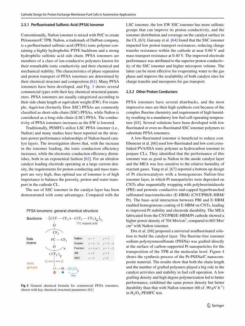
Conventionally, Nafion ionomer is mixed with Pt/C to create Pt/ionomer/C TPB. Nafion, a trademark of DuPont company, is a perfluorinated sulfonic-acid (PFSA) ionic polymer con-taining a highly hydrophobic PTFE backbone and a strong hydrophilic sulfonic acid side chain. PFSA ionomers are members of a class of ion-conductive polymers known for their remarkable ionic conductivity and their chemical and mechanical stability. The characteristics of phase separation and proton transport of PFSA ionomers are determined by their chemical structure and composition [61]. Many PFSA ionomers have been developed, and Fig. 3 shows several commercial types with their key chemical structural param-eters. PFSA ionomers are usually categorized according to their side-chain length or equivalent weight (EW). For exam-ple, Aquivion (formerly Dow SSC) PFSAs are commonly classified as short-side-chain (SSC) PFSAs, while Nafion is considered as a long-side-chain (LSC) PFSA. The conduc-tivity of PFSA ionomers increases as the EW is lowered.
Traditionally, PEMFCs utilize LSC PFSA ionomer (i.e., Nafion) and many studies have been reported on the struc-ture-power performance relationships of Nafion-based cata-lyst layers. The investigation shows that, with the increase in the ionomer loading, the ionic conduction efficiency increases, while the electronic conduction efficiency dimin-ishes, both in an exponential fashion [62]. For an ultralow catalyst loading electrode operating at a large current den-sity, the requirements for proton-conducting and mass trans-port are very high, thus optimal use of ionomer is of high importance to balance the porosity, proton and water trans-port in the cathode CL.
The use of SSC ionomer in the catalyst layer has been demonstrated with some advantages. Compared with the
LSC ionomer, the low EW SSC ionomer has more sulfonic groups that can improve its proton conductivity, and the ionomer distribution and coverage on the catalyst surface in the CL [63]. Garsany et al. [64] found that the SSC ionomer imparted low proton transport resistances, reducing charge transfer resistance within the cathode at near 0.60 V and mass transport resistance at 0.40 V. The improved electrode performance was attributed to the superior proton conductiv-ity of the SSC ionomer and higher micropore volume. The latter can be more effective for evaporating water to the gas phase and improve the availability of both catalyst sites for charge transfer and mesopores for gas transport.
2.3.2 Other Proton Conductors
PFSA ionomers have several drawbacks, and the most impressive ones are their high synthesis cost because of the complex fluorine chemistry and requirement of high humid-ity resulting in a mandatory low fuel cell operating tempera-ture [65]. Several solutions have been developed with low fluorinated or even no-fluorinated SSC ionomer polymers to substitute PFSA ionomers.
A low-fluorinated ionomer is beneficial to reduce cost. Ebenezer et al. [66] used low-fluorinated and low-cost cross-linked PVA/SSA ionic polymer as hydrocarbon ionomer to prepare CLs. They identified that the performance of this ionomer was as good as Nafion in the anode catalyst layer and the MEA was less sensitive to the relative humidity of reactant gases. Yang et al. [67] reported a bottom-up design of Pt electrocatalysts with a homogeneous Nafion-free ionomer layer, in which Pt nanoparticles were deposited on CNTs after sequentially wrapping with polybenzimidazole (PBI) and protonic conductive end-capped hyperbranched sulfonated macromolecules (E-HBM) (CNT/PBI/E-HBM/Pt). The base–acid interaction between PBI and E‐HBM enabled homogeneous coating of E‐HBM on CNTs, leading to improved Pt stability and electrode durability. The MEA fabricated from the CNT/PBI/E-HBM/Pt cathode showed a higher power density of 704 Mw/cm2, compared to 603 Mw/cm2 with Nafion ionomer.
Dru et al. [68] proposed a universal nonfluorinated solu-tion to build the catalyst layer. The fluorine-free ionomer sodium polystyrenesulfonate (PSSNa) was grafted directly at the surface of carbon-supported Pt nanoparticles for the transposition of the TPB at the molecular level. Figure 4 shows the synthesis process of the Pt-PSSNa/C nanocom-posite material. The results show that both the chain length and the number of grafted polymers played a big role in the catalyst activities and stability in fuel cell operation. A low grafting density and high degree polymerization led to better performance, exhibited the same power density but better durability than that with Nafion ionomer (60 cf. 90 μV h–1) in H2/O2 PEMFC test.
Fig. 3 General chemical formula for commercial PFSA ionomers, shown with key chemical structural parameters [61]

H. Wang et al.
1 3
Another strategy recently reported combines ionic liquids (ILs) with Nafion ionomer to extend proton-conducting net-work in CLs. Some ILs possess excellent oxygen solubility and diffusivity, although not as good as Nafion ionomer, they can penetrate the small pores that cannot be reached by the large ionomer cluster thus enhancing catalyst utiliza-tion ratio. Li et al. [69] introduced a sulfonated poly(ionic liquid) block copolymer (SPILBCP) as an additive to Nafion ionomer in the catalyst layer. From an electrode structure point of view illustrated in Fig. 5, LSC Nafion ionomer helps bridging vacancies between isolated SPILBCP aggre-gates under both high and low relative humidity, forming highly connected ionomer networks and facilitating proton transport in the catalyst layer, increasing Pt utilization. The use of superhydrophobic ILs can further help repel the pro-duced water and reduce the surface oxidation of catalysts. For examples, ILs include [MTBD] [beti] (7‐methyl‐1,5,7‐triazabicyclo [4.4.0]dec‐5‐ene bis(perfluoroethylsulfonyl)
imide), [C4C1im] [NTf2] (1-butyl-3-methylimidazolium bis(trifluoromethanesulfonyl)imide) and [BMIM] [NTf2] (1-butyl-3-methylimidazolium bis(trifluoromethylsulfonyl)imide) have been used to modify Pt-based PtNi/C and Pt/C, and PGM-free ZnCoNC catalysts for PEMFC application [70–72]. Importantly, ILs presenting at the catalyst interface can act to prevent the specific adsorption of sulfonate groups of Nafion on Pt surfaces, negating the detrimental impact of the ionomer on reaction rates, specifically for ORR, thus improving PEMFC high current density performance [73]. Improved power performance was successfully demonstrated in either H2/O2 or H2/air MEA test. However, the durability of this approach is still not clear in long-term fuel cell opera-tion, in particular considering the severe higher operating temperature compared to the electrochemical measurement in a liquid electrolyte where the outstanding stability of this IL modification has been shown.
Fig. 4 Pt-PSSNa/C nanocomposite material synthesis process [68]
Fig. 5 Proposed microstruc-ture of 0.6SPILBCP:C and 0.3SPILBCP:C + 0.3Nafion:C electrodes depicting the effect of ionomer distribution on Pt utilization under dry and wet operating conditions [69]

Cathode Design for Proton Exchange Membrane Fuel Cells in Automotive Applications
1 3
2.4 Improving Ionomer/Catalyst Interface
In PEMFC catalyst layers, ionomers are found as nanome-ter-thick “thin films” binding the catalyst particles together, facilitating proton transport through the layer and gas/water transport to and from the catalytic sites, respectively [61].
Homogeneous distribution of ionomer on catalyst sur-face is essential to achieve high-power performance and sus-tained electrode stability, i.e., high ORR kinetics and excel-lent mass transport properties. Typically, the catalyst layer is fabricated starting from catalyst ink, which is prepared by mixing carbon-supported Pt nanoparticle catalysts (i.e., Pt/C), Nafion ionomer, isopropyl alcohol, and water [74]. After thoroughly mixing the catalyst ink to ensure a homog-enous mixture, it is sprayed or coated onto the microporous layer of a GDL for the case of the gas diffusion electrode (GDE), or the membrane for the case of the catalyst coated membrane (CCM) [75]. In improving the ionomer/catalyst interface, the catalyst support structure and surface proper-ties [12, 63], ionomer/catalyst ratio [76] and catalyst ink dispersing methodology [77] all show great influence on the electrode power performance.
The catalyst/ionomer interfacial structure is largely deter-mined by the interaction between Pt and the ionomer side chains, and the density of ionomers is higher in areas of the catalyst surface containing Pt because of the better wet-tability of Pt surface than that of the carbon support [63]. However, the strong adsorption of the sulfonate group of the PFSA ionomer is poison for the Pt surface and reduces the catalyst activity during fuel cell operation. Yamada et al. [78] used dopamine (DA) to protect the Pt catalyst surface from poisoning. The coverage of the adsorbed sulfonates from the ionomer on the Pt surface was decreased with the increasing DA amount. Improved mass activity and dura-bility were achieved. However, this method cannot address the oxygen transport issue at the interface between Pt and ionomer. The power performance at a high current density operation was deteriorated by the modification. Zhou et al. [79] have explored a thin porous layer derived from Nafion formed on the surface of Pt/C catalyst to create a shell to reduce the ionomer poisoning and improve the oxygen accessibility. The experimental results demonstrated a very thin coating that helped to separate the Nafion ionomer and Pt particles in the catalysts exhibiting enhanced fuel cell performance.
Breakthrough in boosting the PEMFC power performance has recently been achieved through tuning structure and sur-face properties of catalyst support to improve the interaction between ionomer and catalysts. Yarlagadda et al. [44] dem-onstrated that porous carbons with a preferred pore size of 4–7 nm endowed catalysts with both excellent ORR activi-ties and transport properties (Fig. 6). Catalysts supported on solid carbon have good transport properties, but are easily
poisoned by the ionomer. In contrast, for catalysts supported on porous carbon, the interior catalyst particles within pores have limited access to protons and reactant gases. And, this effect will become more prominent for an electrode with an ultralow Pt loading operated at a large current density. Compared to solid Vulcan and porous Ketjenblack support, PtCo supported on porous carbon with access pores showed a boosted power performance of 14.3 kW/gPGM with a cath-ode Pt loading of 0.063 mgPt/cm2 (tested at 94 °C with a 50 cm2 MEA under H2/air at 65/65% RH, 250/250 kPaabs and stoichiometries of 1.5/2 at the anode/cathode, respectively). Recent achievements revealed that the ionomer distribution on Pt/C surface can be tailored by modifying carbon sup-port surface. Orfanidi et al. [80] functionalized carbon sup-port with –NHx groups. The coulombic interaction between –NHx groups and negatively charged –SO3
− of the iono-mer side-chains promoted the homogeneous distribution of the ionomer on Pt/C catalyst surface, although the stability of –NHx groups to sustain the suppression of local oxygen transport losses is still an issue. As an advancement, N-mod-ified ketjenblack has been recently studied by Ott et al. [12] The surface N-modification of carbon support with tailored porosity imparted controlled deposition of Pt nanoparticles in or close to carbon pores, and also a uniform coverage of ionomer on the support surface. This also led to a lower degree of Pt surface poisoning by ionomer. With the new catalyst design, single cells with a cathode Pt loading of 0.11 mgPt/cm2 displayed a large power density of 1.39 W/cm2 and high stability under voltage cycling (1.4 cm2 MEAs, tested at 80 °C with fully humidified H2/air at a pressure of 230 kPaabs and constant flow of 1000/2000 normal cubic centimeters).
The effect of sonication degree on the preparation of cata-lyst ink was studied using in-situ X-ray scattering [77]. A
Fig. 6 Comparison of ORR kinetic and transport (O2 and proton) characteristics of CLs made from solid, porous and accessible porous carbon support (gray). Small black and gray circles represent rela-tively high and low activity Pt particles, respectively, due to ionomer (blue) adsorption [44]

H. Wang et al.
1 3
combination of tip and bath sonication was demonstrated as an efficient way to break down carbon agglomerates into small aggregates without detaching the supported Pt nanoparticles. Three dispersed states were proposed and are shown in Fig. 7. With insufficient sonication, the primary agglomerates are not broken; thus, the interior Pt nanopar-ticles are not accessible for proton conducting ionomer. In contrast, excessive sonication led to Pt nanoparticle detach-ing from the carbon support. For the case of appropriate sonication, the ionomer is uniformly distributed on the bro-ken agglomerates, resulting in high catalyst utilization as well as low mass transport resistance. An investigation on dynamic light scattering (DLS) also suggested that larger agglomerates might help the formation of holes in the CL for gas diffusion and water removal, with the optimum size found to be around 400–800 nm [19]. Therefore, good con-trol of the dispersion process is essential to achieve high electrode power performance.
The influences and mechanisms of the solvents mixed into catalyst ink were also investigated. The mixture of PFSA ionomer and organic solvents have three states: solution (ε > 10), colloid (3 < ε < 10) and precipitate (ε < 3), according to the dielectric constant ε of organic solvents, and the electrode prepared by a colloidal method usually shows better results [81]. Isopropyl alcohol (IPA) is the most commonly used solvent. Other solvents, such as glycerol [82], N-methyl-2-pyrrolicone (NMP) [83] and polyethylene glycol (PEG) [84] have been explored to increase the catalyst-water-ionomer interface. Kim et al. [85] investigated the mobility of the polymeric chains in Nafion ionomer dispersion in IPA, dimethyl sulfoxide (DMSO) and NMP. It was found the solvents with high main-chain mobility led to a more intimate contact at the TPB thus a better electrochemical property, which was mainly attributed to the strong interaction between the
solvent molecule and Nafion ionomer. On the effects of the H2O content, there are conflict opinions. It was consid-ered that increasing the water content resulted in increased carbon aggregation and low ionomer coverage with a large thickness [86]. It was also demonstrated that the ionomer aggregate size in the water-rich inks decreased resulting in enhanced ionomer/Pt interaction [87]. The reduced iono-mer aggregation improved oxygen transport resistance through the ionomer film, while the increased adsorption led to enlarged resistance at the ionomer/Pt interface.
3 Microstructure of Catalyst Layers
The microstructure of the CL determines its mass transport characteristics, which in the cathode include both oxygen supplying and water removal.
3.1 Porous Structure within Catalyst Layers
The catalyst layer, usually made of Pt/C catalysts and iono-mer, is a porous medium with randomly distributed hydro-phobic and hydrophilic sites. Within the cathode, the ORR occurs at the TPB zone in the CL [88]. To complete fuel cell reactions, transport networks are necessary within the CL for transferring reactants (O2/air at the cathode), electrons and protons to catalytic reaction sites and repelling gener-ated water out of the CL [89]. According to a pore-scale CL model based on the lattice Boltzmann method (LBM) to simulate reactive transport processes by Hou et al. [76], an ideal structure design, which simultaneously ensures a large active catalyst area and extremely low transport losses, can enhance the power performance by 50%.
Fig. 7 Proposed structure of Pt/C and Nafion ionomer with different ink processing procedures [77]

Cathode Design for Proton Exchange Membrane Fuel Cells in Automotive Applications
1 3
A highly porous structure is essential for the CL, but the negative aspect is that electronic and ionic conduc-tion efficiency decreases linearly with the porosity [62]. To control the geometrical parameters of pores, pore size distribution and porosity can be tailored by porosity enhancers, "pore-forming" agent [90, 91], carbon black support [92] and catalyst ink composition (ionomer to carbon ratio, etc.) [93, 94]. A new concept of in-situ pore generation to reduce water flooding in the cathode catalyst layer (CCL) based on sulfonated polyether ether ketone Sulfonated polyether ether ketone (SPEEK) has been pro-posed by introducing water-soluble PEG as a pore gen-erator. During the fuel cell operation, PEG was dissolved in water produced and removed to form controlled pores [91]. Suzuki et al. [93] reported that the ionomer content was the determinative factor of CL void volume. Tagh-iabadi et al. [95] evaluated the performance of different void volumes and found a 20.8% CCL porosity leading to the best MEA performance. Sassin et al. [96] examined the interplay between the porosity and thickness of the CCL on its mass transport limitations in PEMFCs. They showed that the highest power performance was delivered by a 7.5-μm-thick CCL because of an optimal balance between solid and void networks.
The interplay of wettability and pore sizes influences water distribution within the CL, microporous layer (MPL) of the GDL and specifically their interface [97]. Thereby, in addition to the porosity, hydrophobicity and hydro-philicity feature of the CCL have been investigated as another way to improve its mass transport characteristics for enhancing MEA performance [98]. While it was found that an anode with hydrophilic property helped improve the fuel cell power performance in low humidity opera-tion, excessive hydrophilicity in the cathode caused water
flooding. Oh et al. [99] and Li et al. [100] introduced poly (vinylidene fluoride-co-hexafluoropropylene) and dime-thyl, respectively, to increase the hydrophobicity of the CCL, improving both oxygen diffusion and water manage-ment. Chi and coworkers [101] utilized CNTs as poros-ity enhancers and PTFE as a surface modulating agent to develop MEAs possessing highly porous CCL struc-tures with great hydrophobicity. Figure 8 shows scanning electronic microscopy (SEM) images of the surface and cross-sectional structure of the MEAs with different CCL compositions. At 0.7 and 0.6 V, the MEA exhibited larger current densities of 1 and 1.55 A/cm2, respectively, com-pared to 0.75 and 1.2 A/cm2 of the one without CNTs and PTFE. However, too many hydrophobic materials (e.g., PTFE) also block the pores leading to high mass trans-port resistance in the CCL. Thereby, a balance between the large porosity and high hydrophobicity can be highly beneficial for improving the fuel cell power performance.
3.2 Diffusion Principles in Catalyst Layers
The oxygen diffusion in the CL includes three parts: molecu-lar diffusion, Knudsen diffusion and permeation through the ionomer film surrounding the catalyst agglomerates. For a CCL with an ultralow catalyst loading, the contribution of oxygen penetrating through the ionomer film is a major part of the total mass transport resistance [102]. This resistance can be significantly reduced by improving the ionomer dis-tribution to form a homogeneous thin layer on the catalyst surface. Potential strategies include modifying the catalyst support (e.g., NH3 or N– groups functionalizing carbon sup-port), using SSC ionomer or even combining with ILs, [12, 64, 69, 80] which have been discussed in Sect. 2. The diffu-sion mechanism in the gas phase of the CL can be split into
Fig. 8 SEM images of the surface and cross-sectional structure of: a, d MEA-0CNT-0PT (without CNTs or PTFE added); b, e MEA-15CNT-0PT (with only 15 wt% CNTs added); and c, f MEA-15CNT-30PT(with 15 wt% CNTs and 30% PTFE add) [101]

H. Wang et al.
1 3
Knudsen diffusion by collisions between the molecules and pore walls, and bulk (or molecular) diffusion occurring with collisions between the molecules [103].
Catalyst layers with the same porosity can have very dif-ferent tortuosity and diffusivity. The tortuosity factor of CLs is much larger than the generally well-known tortuosity fac-tor of porous media, which is attributed to the existence of isolated pores and non-spherical dead-end pores. The exist-ence of isolated pores substantially affects gas diffusion in the CL, while the formation of non-spherical dead-end pores can lead to a higher tortuosity factor [104].
Oxygen effective diffusivity, Deff, is defined as a function of the porosity ε, the tortuosity τ and oxygen diffusivity in the pore scale D, which can be expressed by:
Oxygen diffusivity D in the pore scale can be approxi-mated by Bosanquet’s formula as the following:
where DKn and Dbulk represent Knudsen diffusivity and bulk diffusivity, respectively.
The oxygen diffusion in the gas phase of the CL is domi-nated by the Knudsen effect [105]. Isolated pores resulted in a substantial increase of the tortuosity factor τ and thus a decrease of the effective gas diffusivity Deff. The dead-end pores can be another factor affecting Deff. The isolated pores and the dead-end pores were formed by ionomer deposition onto Pt/C agglomerates. And support materials would result in different tortuosity within the CL [104]. Within a CL with an ultralow catalyst loading, the influence of Knudsen dif-fusion becomes less important [102]. However, under high-current–density operation conditions, the large amount of liquid water generated at the cathode can significantly reduce the effective porosity, and flooding is severe which limits oxygen transport. On the contrary to the flooding, efficient retention of the liquid water generated from the cathode is also preferred in some cases. A strategy can be used to alle-viate the operation dependence on external humidification of air feed because the commonly used PFSA ionomer requires to be kept humid to attain reliable proton conductivity [103]. Therefore, electrode structure with a good balance of poros-ity, tortuosity and water management (i.e., hydrophilic and hydrophobic feature) is still highly preferred for electrodes with a low catalyst loading, e.g., CLs with 3D-ordered structure.
3.3 Catalyst Layers with 3D‑Ordered Structure
The distribution of pores, proton conductors and electronic conductors is random in conventional Pt/C nanoparticle
(1)Deff = (�∕�)D
(2)D =[
(
DKn)−1
+(
Dbulk
)−1]−1
electrodes in PEMFCs. This results in a very low catalyst utilization (20–30%) and high oxygen transport resistance at large-current-density operations. The development of 3D-ordered CLs from aligned 1D nanostructures is regarded as the most promising approach to address this challenge and boost fuel cell performance. With well-designed porosities, the electrodes with aligned 1D nanostructures can provide a super-high utilization percentage of active sites exposed with significantly improved mass transfer performance. Mid-delman et al. [106] firstly came up with the concept of the ideal electrode structure, in which all electronic conductor, proton conductor and pores are oriented along with the cor-responding transport directions. A few reports and reviews have been published on 3D-ordered electrodes for PEMFCs, which can be roughly divided into catalyst support and cat-alyst-based ordered structures [107, 108].
3.3.1 Ordered Catalyst Support Structure
The aligned catalyst support materials reported for fabricat-ing 3D-ordered electrodes mainly include polymer whiskers and nanowires, carbon nanotubes and fibres, and metal oxide nanotubes and nanorods. Nanostructured thin film (NSTF) or nanoparticle catalysts are usually deposited on the aligned support surface using physical sputtering techniques. A typi-cal preparation process of an ordered electrode is shown in Fig. 9.
One significant development of this type of 3D-ordered electrodes is the NSTF catalyst layer from the 3 M Com-pany. This technology has been mentioned in many review papers although there’re still some big challenges faced by commercialization after more than 20 years of develop-ment. The NSTF electrode is composed of arrays of oriented short (less than 1 μm in length) crystalline organic-pigment whiskers, fully covered by a thin Pt or Pt-based alloy cat-alyst layer deposited by a vacuum sputter technique. The open ordered structure and small thickness of the CL enable improved oxygen mass transport and better accessibility of the Pt active sites, along with the proton transport occurring through the water trapped within the catalyst nanostructures, finally leading to superior power performance [50, 110]. However, low electrochemical active specific area (ECSA) and flooding issues limit the real application of this NSTF catalyst [111]. As an alternative to organic pigment whisk-ers, polypyrrole (PPy) and polyaniline (PAni) nanowire arrays have also been reported for this application in PEM-FCs [112–114].
Compared with 1D polymer supports, 1D carbonaceous materials possess better electrical conductivity and also excellent stability. Tian et al. [109] prepared electrodes with vertically aligned carbon nanotubes (VACNTs) sup-ported Pt nanoparticles (Fig. 9). The best electrode power performance was recorded with an ultra‐low Pt loading

Cathode Design for Proton Exchange Membrane Fuel Cells in Automotive Applications
1 3
of 0.035 mg/cm2, which showed a comparable power density to that of a commercial Pt/C (40 wt% Pt/C from Johnson Matthey, JM) electrode with 0.4 mgPt/cm2. Meng et al. [16] reported a novel bi‐functional layer consist-ing of VACNTs and PtCo nanoparticles catalysts (PtCo/VACNTs) with well‐aligned channels, which greatly facili-tated fast transport of oxygen, electron, water and proton inside the CL. Moreover, as shown in Fig. 10, by pre-cise manipulation of the surface hydrophilic‐hydrophobic and pore structure of the PtCo/VACNTs, the Janus‐type surface coupled with high porosity makes it suitable for water management and gas diffusion. The structure also successfully eliminated the commonly used MPL layer. The bi-functional PtCo/VACNTs cathode with an ultralow Pt loading of 0.065 mgPt/cm2 showed a higher peak power density of 1.41 W/cm2 compared to 1.31 W/cm2 of the one with commercial Pt/C catalysts (JM, 40 wt%) at a loading of 0.4 mgPt/cm2. However, by the physical sputtering tech-nique, there is a big challenge to achieve a high catalyst loading. Thereby, the optimal power density recorded is usually only comparable or slightly higher than the Pt/C electrodes with a medium catalyst loading. Although the ultralow loading can reduce the catalyst cost, there are still big challenges to realize a real high-power-density opera-tion. In view of this drawback, Du’s group [115] designed CLs from 1D Pt catalysts deposited on VACNTs by a facile wet chemical method. With a catalyst loading of 0.19 mgPt/cm2, the electrode showed 23% higher power density at 0.6 V than that of a Pt/C (TKK, 45.9 wt%) electrode with a catalyst loading of 0.41 mgPt/cm2.
Compared with carbon materials, metal oxides like TiO2 [116] and WO3 [117], which are facile to construct nanoarray structures and exhibit better acid and corrosion
resistance, have also been utilized as support. Zhang et al. [118] prepared ordered TiO2 nanotube arrays followed by hydrogen annealing to improve their electronic conduc-tivity. PtPdSn ternary alloy catalysts were subsequently supported by precursor impregnation and hydrogen reduc-tion at high temperatures to prepare the CL. To modu-late the conductivity of TiO2 support, Chen et al. [119] developed Pt-TiO2@PANI core–shell nanowire arrays in-situ grown on GDLs. With a cathode catalyst loading of 0.2 mg/cm2, the Pt-TiO2@PANI electrode showed a peak power density that is 0.77 W/cm2 higher than 0.70 W/cm2 of a commercial Pt/C electrode (JM, 40 wt%). To further improve the TiO2 conductivity, Jiang et al. [120] prepared TiO2 nanorod arrays on carbon paper with a seed–assisted hydrothermal method and converted it into TiO2-C NR arrays by heat treatment at 900 ℃ under methane atmos-phere. Pt nanoparticles are subsequently deposited by physical vapor deposition to fabricate Pt-TiO2-C CLs.
3.3.2 Ordered Catalyst Structures
Apart from the construction of the ordered support structure, arrays of 1D catalyst nanostructures, i.e., Pt and Pt alloy nanowires and nanotubes, are also introduced to fabricate 3D-ordered CLs.
By a facile in-situ growing approach using a formic acid-reducing method, Du et al. [121, 122] developed gas dif-fusion electrodes (GDEs) with Pt nanowires arrays in-situ grown on GDLs. The simple one-step fabrication procedure was achieved in an aqueous solution at room temperature, without using any template or organic solvent. However, the hydrophobic GDL surface limits its surface wettable abil-ity with the aqueous reaction solution, resulting in the for-mation of large Pt nanowire agglomerates. To improve the
Fig. 9 Schematic illustration of the synthesis of Pt catalysts on vertically aligned carbon nanotube (VACNTs) and fabrication of the membrane electrode assembly [109]

H. Wang et al.
1 3
distribution of Pt nanowires to reduce the mass transport resistance and enhance the catalyst utilization, Pd nanoseeds [123], high growing temperature [124] and plasma nitriding treatment [125] have been explored to create more nuclea-tion sites on the GDL surface to induce the Pt nanowire growth. Thin CLs with a monolayer array of ultrathin Pt nanowires with a diameter of ca. 3 nm were achieved, and better power performance was demonstrated compared to the latest commercial TKK Pt/C catalysts. As an advancement of this approach, Sui et al. grew Pt nanowire arrays on PEM [126, 127] and decal [128] substrate (e.g., PTFE sheet) by introducing a carbon matrix layer for enabling nucleation sites to overcome the inert surface challenge. By introduc-ing a very small amount of Pt/C (0.005 mgPt/cm2) into the carbon matrix [129], the nanowire distribution was further improved. With a total cathode Pt loading of 0.205 mgPt/cm2, the Pt nanowire electrode showed a comparable power density as the GDE made from commercial Pt/C catalysts (JM, 40 wt%) with a loading of 0.4 mgPt/cm2. However, because of the large bulk volume of the anisotropic Pt nanowires, their ECSA are usually much lower compared to Pt/C nanoparticle catalysts. The development of electrodes from single-crystal 1D Pt-based alloy catalyst arrays [130, 131]can be a potential solution to address this issue. How-ever, their facile preparation for practical application is still highly challenging at the moment.
Another potential strategy is to use porous 1D nanostruc-tures, e.g., Pt or Pt alloy nanotubes. Besides the conventional anodized aluminium oxide (AAO) template method [132], ZnO nanorod arrays in-situ grown on GDL surface by a hydro-thermal method were also explored as the sacrificial template [65]. Pt was deposited by physical vapor deposition (PVD), and the template was removed to obtain Pt nanotube array electrodes. Electrodes from PtCo bimetallic nanotube arrays were also demonstrated by using templated Co–OH–CO3 nanowire arrays (NWAs) with surface Pt coating using the magnetron sputtering technique [133]. However, due to the large size of the prepared catalyst nanotubes (diameter of 90–100 nm and wall thickness of 8–17 nm) and the limit in achieving a high catalyst loading by the PVD technique, the nanotube array electrodes both showed lower power densities than that from commercial Pt/C catalysts in the fuel cell test.
4 High‑Power‑Density Operation
4.1 Mass Transport at Large Current Density Operation
Enhancement of fuel cell performance at large current densi-ties is essential to achieve high-power-density operation and reduce system cost in automotive applications. The concen-tration polarization is the major barrier to achieving high performance at a large current density operation. It is caused
Fig. 10 The schematic illustration of a the conventional MEA structure, b the Janus highly ordered bi‐functional layer with super gas–water dif-fusion capability, and c problems related to the additional MPL layer for ordered‐structured MEA [16]
Cathode Design for Proton Exchange Membrane Fuel Cells in Automotive Applications
1 3
by the mass transport resistance of reactants (O2, H2) and product (water) taking place near active catalytic sites [134]. Besides, the transport of liquid water in the CL also affects the membrane and electrode humidification states, as well as the internal resistance and catalyst efficiency that deter-mine fuel cell performance [135]. A large operating current density may result in oxygen starvation at the catalyst sur-face because of the high water formation rate at the cathode. Thereby, appropriate water/heat management is essential for proton conducting and reactant transport, mitigating severe performance loss in operation [136].
There are two major strategies applied to achieve high-power performance at large-current–density operation: opti-mization engineering of the electrode structure and MEA configuration, and minimizing mass transfer resistance by providing the best operating conditions for electrochemical reactions in the optimal CL [8]. Ramaswamy and Kumarag-uru [137] proposed that the material and design selection in the CL affected the local-O2 and bulk-H+ transport thus improving large current density performance in PEMFCs. An MEA with uniform size distribution and homogeneous local dispersion of Pt nanoparticle catalysts showed a superb performance with a potential enhancement of 29 mV at 1.6 A/cm2 [138]. Lee et al. [139] investigated increasing the average pore size from 50 to 60 nm in the CL by introducing PEG addition to catalyst ink to achieve reduced mass trans-port resistance in operation. Besides the above-mentioned innovation of material and electrode structure, other efforts reported related to mass transfer inside the MEAs were focused on water/heat management, flow field design and the humidification strategy at the fuel cell stack level for a full play of the MEA potential [8].
4.2 Development and Application Status of PEMFCs for Vehicles
FCVs have advanced rapidly in recent years as the auto-motive OEMs have released commercially available FCV models. According to Global EV Outlook 2020 from Inter-national Energy Agency (IEA), total sales of FCVs in 2019 were 12,350, adding the global stock to 25,210 units. Pas-senger cars account for the majority of FCV sales and stocks. Toyota (Mirai), Hyundai (Nexo) and Honda (Clarity Fuel Cell) are the main players of the current FCV market. Toy-ota has also unveiled its second-generation Mirai concept in 2019 [140]. Additionally, expert assessments of the cost and expected future performance of PEMFCs for FCVs were reported under the DOE support [141]. Thirty-nine experts, spreading across academia, government and industry, were interviewed to assess system cost, stack durability and power density. Most experts identified high PGM loading as the most significant barrier. Improving stack to operate at a high-power density is considered as the most potential
strategy to reduce the amount of expensive materials and, therefore, stack cost.
PEMFCs used in the second-generation Mirai represent the state-of-the-art development in this area. To reach high-power performance at large current density operation, an innovative cell flow field plate is adopted to improve gas diffusion and lower concentration overvoltage, and new electrode structures are developed to increase proton con-ductivity for a lower resistance overpotential and boost catalytic activity for lower activation loss. As a result, the maximum sweep current per unit area of the electrode improved substantially, increasing the current density by a factor of 2.4 compared to the PEMFC in the first-generation Mirai launched in 2014 [142]. Figure 11 shows the fuel cell polarization curve of the first-generation TOYOTA Mirai. This graph was generated under the condition of NEDCx2, UDDSx3, Highwayx2, US06 × 2, maximum acceleration × 3 and steady-state speed tests [143]. All of the collected data are shown in the red dots, including a set of the stack map-ping data and the mapping minimum cell data. The fuel cell stack consists of 370 cells and each cell has an active area of 237 cm2. It delivers a peak power of 114 kW with a volume power density of 3.1 KW/L and a weight power density of 2.0 kW/kg1. Very recently the early released data reports that these parameters have been improved to 128 kW, 4.4 kW/L and 4 kW/g, respectively, for the second-generation Mirai.
More recently, in a commercialization-focused project under the EU FCH2-RIA Funding Scheme of "Volume Manufacturing of PEM FC Stacks for Transportation and In-line Quality Assurance (VOLUMETRIQ)," a full-size stack developed with 299 cells provided a total power of 111 kW. Figure 12 shows the stack polarization plot under the Elring-Klinger AG (EK, DE) optimized conditions, delivering 2.5 A/cm2 at 0.6 V. By associated improvements in the iono-mer used for the membrane, cathode catalyst construction, compression set, GDLs and cell hardware, VOLUMETRIQ has achieved a leading single-cell power density of 2.67 A/cm2 at 0.6 V (1.6 W/cm2) with catalyst-coated membranes
Fig. 11 Toyota Mirai fuel cell polarization curve [143]

H. Wang et al.
1 3
(CCMs) produced at volume. Based on the full stack result, the calculated volumetric power density reached 5.4 kW/L including endplates and 6.6 kW/ L on the cell block, which is above the state-of-the-art fuel cell technology [144].
A high-performance proton exchange membrane (PEM) fuel cell stack in an industry-leading volumetric high-power density of 4.3 kW/L excluding plate hardware, with high-power output up to 130-kW rated power and 140-kW maxi-mum power, was launched by Ballard Power Systems in Sep. 2020.
Many governments have formulated roadmaps for FCVs. The DoE objectives are to develop a 65% peak-efficiency and direct hydrogen fuel cell power system for transportation that can achieve 5000-h durability (ultimate 8000 h) and be mass-produced at 40 USD/kW by 2020 (ultimate 30 USD/kW) [145]. The Fuel Cells and Hydrogen Joint Undertaking (FCH JU) published FUTURE TARGETS of Fuel Cell and Hydrogen-Transport Applications as derived from the Multi Annual Work Plan, as shown in Table 1 [146].
While much progress has been made and the current parameters are much closer to meeting the DOE 2020 tar-gets, FCV manufacturers will need to make improvements to achieve the goal of 65% peak efficiency [147]. The Ministry of Economy, Trade and Industry (METI) in Japan announced the revised New Strategic Roadmap for Hydrogen and Fuel Cells in September 2019. The target of the volumetric power density of PEMFC stacks for transportation will achieve 6.0 kW/L with a PGM loading of 0.1 g/kW by 2030 [148].
In Europe, FCH JU, a unique public–private partnership, continues supporting research, technological development and demonstration activities in fuel cell and hydrogen energy technologies. In a recent FCH2-RIA call (FCH-01–2-2020) of "Durability-Lifetime of Stacks for Heavy-Duty Trucks" expected for 3-year duration, the main targeted KPIs are to achieve (i) power density > 1.2 W/cm2 at 0.675 V/cell; (ii) PGM loading < 0.3 g/kW; and (iii) system durability: 30,000 projected hours with less than 10% performance loss at nominal power.
Further improvement of the fuel cell stack, especially on a significant reduction of the cathode Pt loading to below 0.1 mgPt/cm2, should be achieved for PEMFCs to operate at a large current density, i.e., at a high-power density, in order to keep the overall stack size and cost small in large-scale commercialization of FCVs.
5 Perspectives and Summary
The above discussions of the catalyst and ionomer develop-ment, ionomer/catalyst interface, pore feature controlling and 3D-ordered catalyst layers provide a basis for under-standing the function of interface, structure and transport phenomena in the catalyst layer and aid the rational design of cathodes for high-power-density operation. As a functional cathode, the essential factors to deliver high-power perfor-mance in practical operation include well-connected network of catalysts and support for electrons to move to active cata-lytic sites, well-linked ionomer paths for effectively transfer-ring protons and interconnected pores through the catalyst layer to bring oxygen to the triple-phase boundary and take generated water out. The conventional Pt/C cathodes, after the nearly half-century development, can provide a power density up to 1.39 W/cm2 and are still commonly used in commercial PEMFCs. However, they are still limited to the relatively low-power performance and durability in fuel cell operation, and high oxygen transport losses because of the randomly distributed catalysts and pores, which are still great technical hurdles in developing PEMFCs for high-power-density operation.
In the context of developing highly active catalysts, the investigations were mainly focused on Pt-based alloy catalysts to improve catalytic activities, and core–shell and
Fig. 12 Stack IV plot under the "VOLUMETRIQ" of FCH2-RIA Funding Scheme [144]
Table 1 Fuel cell system specifications by FCH JU FUTURE TARGETS [147]
Parameter Unit Target 2020 Target 2024 Target 2030
Fuel cell system durability h 5000 6000 7000Fuel cell system cost EUR/kW 60 50 40Areal power density W/cm2 1.5 1.8 2.0PGM loading G/kW 0.17 0.08 0.05Cell volumetric power kW/L 7.3 9.3 10.0

Cathode Design for Proton Exchange Membrane Fuel Cells in Automotive Applications
1 3
alternative PGM-free catalysts to reduce the catalyst cost. So far, Pt-based catalysts still outperform other catalysts over an entire range of properties. PtNi and PtCo catalysts have been demonstrated as the most promising catalysts, and the PtCo catalyst is also the one deployed in Toyota Mirai FCVs. While most exciting catalytic properties have been reported from advanced shape-controlled catalysts from PtNi alloys, e.g., nanoframes, nanopellets and nanowires, most of them were only demonstrated by half-cell electro-chemical measurement using the RDE technique in liquid electrolytes and don’t work in practical electrodes in single fuel cells. In recent years, the established floating electrode technique and the half-cell gas diffusion electrode technique enable the testing of advanced electrocatalysts at a relatively high catalyst loading and large current density under more realistic operation conditions. These stepwise approaches can potentially bridge the catalytic performance evaluation between the RDE and MEA approaches, shedding light on the engineering of advanced catalysts and bringing them to PEMFC applications, in particular the ultrafine jagged Pt nanowire that shows an ECSA of 118 m2/gPt and the high-est mass activity (13.6 A/gPt) reported so far [40]. Electro-chemical engineering research for a full projection of the outstanding catalytic performance of these advanced cata-lysts in real electrodes could have a significant contribution to the PEMFC development.
For PEMFCs with an ultralow Pt loading catalyst oper-ating at a high-power density, the contribution of oxygen transfer characteristics will differ from those in common medium catalyst loading devices. Thereby, quantifica-tion and separation of various oxygen transport resistance including molecular diffusion, Knudsen diffusion and oxygen penetrating through the ionomer layer on catalyst surface will be highly beneficial to understand the bottle-neck limits for improving power performance of cathodes and pinpointing the investigation to effectively address the challenge. For example, St-Pierre. et. al [102] developed the curve fitting method to be applied in the power densi-ties recorded from the single-cell test under different oxy-gen concentrations in various inert gases (e.g., N2, CO2, He), taking the advantages of the relationship between molecular diffusion and diluted molecular mass, as well as the independence of Knudsen diffusion with the oxygen concentration. While this complex method can give a use-ful estimation for various parts of the oxygen diffusion, a further advancement to provide accurate data with a sim-ple approach could be more valuable for the practical test.
For PEMFCs with an ultralow catalyst loading, the ionomer permeability resistance (for oxygen penetration) will become a major contribution to the oxygen transport resistance. In this case, precisely controlled distribution of ionomer on catalyst surface is of great importance to cre-ate optimized interfacial structure and phenomena. This
is determined by the properties of both ionomer itself and catalyst support surface. Regarding the ionomer, PFSA types are currently the best choice for developing large-current-density operation cathodes. The development of SSC PFSA ionomers has been demonstrated as a success to improve the proton conductivity and gain better distribution on the cata-lyst surface to create a high micropore volume in the cata-lyst layer. But for isolated catalyst agglomerates coated with an SSC ionomer, a combination with LSC ionomers (e.g., Nafion) can help bridge vacancies to form highly connected ionomer networks in the catalyst layer. Another choice is to use hydrophobic protic ionic liquids together with the LSC ionomers, taking advantage of their easily penetrating into the pores, excellent proton conductivity, good oxygen solu-bility and diffusivity and high water-repelling nature. But, to really make this approach work, their stability needs to be dramatically improved for severe fuel cell operating condi-tions. The research of polymerization with well-controlled structure could be a potential solution to this issue. Concern-ing surface modification of the catalyst support to achieve uniform distribution of ionomers, breakthroughs have been achieved through the carbon support functionalization with NHx or nitrogen groups, which also demonstrated the signifi-cant importance of ionomer distribution to improve oxygen mass transport characteristics within the catalyst layer. The design of the carbon support with controlled open pore size excess can also be a large contribution to improve fuel cell performance. To achieve this, a careful balance is neces-sary between trapping catalyst nanoparticles within pores to avoid poisoning by direct contact with ionomers and as close as to the surface to be accessible for oxygen and proton transfer. The use of SSC ionomers and ILs can play a big role here. Fundamental research of the adhesion force between the ionomers and catalyst surface can be an effective tool to monitor their interaction to help the surface optimization of catalyst or catalyst support, in particular in searching for a useful approach to distributing ionomer on the highly active shape-controlled catalysts that possess complete different surface properties to the carbon support, e.g., for building effective TPB within the electrodes from nanowires to fully transfer their high catalytic activities to fuel cells.
Given that the 3D-ordered catalyst layer is effective for facilitating molecular and Knudsen diffusion based on their open porous structure and thin catalyst layer [149], the adop-tion of highly active catalysts can be a promising strategy to realize high-power-density operation. However, the current approach by depositing catalyst nanoparticles using physi-cal techniques on 1D support arrays is limited to the low catalyst loading and ECSA. Although a very high specific power density can be obtained, the fuel cell power density is still lower compared to the conventional Pt/C electrode with a medium catalyst loading. If 3D-ordered electrodes can be built from ultrafine jagged Pt nanowire arrays, their large

H. Wang et al.
1 3
ECSA and high mass activity can address these challenges, thus enabling PEMFCs for high-power-density operation.
In summary, the progress of catalysts, ionomers, elec-trode structure together with advanced stack design have reached a volume power density of 4.4 kW/L for PEMFCs in the second-generation Toyota Mirai FCVs. Next-generation PEMFCs, if intended to achieve 6 kW/L, should possess oxygen mass transport properties that using an ultralow loading of highly active Pt-based catalysts, uniform distri-bution of ionomer on the catalyst surface with minimized ionomer permeability resistance and catalyst poisoning, 3D-ordered catalyst layers with significantly reduced oxy-gen molecular and Knudsen diffusion resistance. This will require multi-disciplinary research joining electrochemical engineering study to provide fundamental knowledge and understanding of the adhesion of ionomers on the catalyst and support surface, agglomeration phenomena of catalysts and ionomers, quantification and separation of oxygen trans-port resistance, and oxygen and water permeability through the thin ionomer layer on the catalyst surface.
Acknowledgement SD would like to acknowledge support from the Engineering and Physical Sciences Research Council (EPSRC, EP/L015749/1). SS gratefully acknowledges the financial supports from the National Natural Science Foundation of China under grant agree-ment No 21576164. Thanks are also to the support from Guangdong Academy of Sciences project (2019 GDASYL-0503005).
Declarations
Conflict of interest On behalf of all the authors, the corresponding au-thor states that there is no conflict of interest.
Open Access This article is licensed under a Creative Commons Attri-bution 4.0 International License, which permits use, sharing, adapta-tion, distribution and reproduction in any medium or format, as long as you give appropriate credit to the original author(s) and the source, provide a link to the Creative Commons licence, and indicate if changes were made. The images or other third party material in this article are included in the article’s Creative Commons licence, unless indicated otherwise in a credit line to the material. If material is not included in the article’s Creative Commons licence and your intended use is not permitted by statutory regulation or exceeds the permitted use, you will need to obtain permission directly from the copyright holder. To view a copy of this licence, visit http:// creat iveco mmons. org/ licen ses/ by/4. 0/.
References
1. Perng, S., Wu, H.: Effect of the prominent catalyst layer surface on reactant gas transport and cell performance at the cathodic side of a PEMFC. Appl. Energy 87(4), 1386–1399 (2010). https:// doi. org/ 10. 1016/j. apene rgy. 2009. 08. 006
2. Vignarooban, K., Lin, J., Arvay, A., Kolli, S., Kruusenberg, I., Tammeveski, K., Munukutla, L., Kannan, A.M.: Nano-elec-trocatalyst materials for low temperature fuel cells: a review. Chin. J. Catal. 36(4), 458–472 (2015). https:// doi. org/ 10. 1016/ s1872- 2067(14) 60175-3
3. Wang, Y., Long, W., Wang, L., Yuan, R., Ignaszak, A., Fang, B., Wilkinson, D.P.: Unlocking the door to highly active ORR catalysts for PEMFC applications: polyhedron-engineered Pt-based nanocrystals. Energy Environ. Sci. 11(2), 258–275 (2018). https:// doi. org/ 10. 1039/ C7EE0 2444D
4. Cindrella, L., Kannan, A.M., Lin, J.F., Saminathan, K., Ho, Y., Lin, C.W., Wertz, J.: Gas diffusion layer for proton exchange membrane fuel cells—a review. J. Power Sour. 194(1), 146–160 (2009). https:// doi. org/ 10. 1016/j. jpows our. 2009. 04. 005
5. Kongkanand, A., Mathias, M.F.: The priority and challenge of high-power performance of low-platinum proton-exchange membrane fuel cells. J. Phys. Chem. Lett. 7(7), 1127–1137 (2016). https:// doi. org/ 10. 1021/ acs. jpcle tt. 6b002 16
6. Ferreira-Aparicio, P., Chaparro, A.M., Antonia, F.M., Conde, J.J., Brightman, E., Hinds, G.: Degradation study by start-up/shut-down cycling of superhydrophobic electrosprayed catalyst layers using a localized reference electrode rechnique. ACS Appl. Mater. Interfaces 9(12), 10626–10636 (2017). https:// doi. org/ 10. 1021/ acsami. 6b155 81
7. Ohyagi, S., Sasaki, T.: Durability of a PEMFC Pt-Co cathode catalyst layer during voltage cycling tests under supersaturated humidity conditions. Electrochim. Acta 102, 336–341 (2013). https:// doi. org/ 10. 1016/j. elect acta. 2013. 04. 060
8. Deng, X., Zhang, J., Fan, Z., Tan, W., Yang, G., Wang, W., Zhou, W., Shao, Z.: Understanding and engineering of mul-tiphase transport processes in membrane electrode assembly of proton-exchange membrane fuel cells with a focus on the cath-ode catalyst layer: a review. Energy Fuels 34(8), 9175–9188 (2020). https:// doi. org/ 10. 1021/ acs. energ yfuels. 0c021 01
9. Escribano, S., Aldebert, P., Pineri, M.: Volumic electrodes of fuel cells with polymer electrolyte membranes: electrochemi-cal performances and structural analysis by thermoporometry. Electrochim. Acta 43(14), 2195–2202 (1998). https:// doi. org/ 10. 1016/ S0013- 4686(97) 10108-6
10. Prasanna, M., Cho, E.A., Lim, T.H., Oh, I.H.: Effects of MEA fabrication method on durability of polymer electrolyte mem-brane fuel cells. Electrochim. Acta 53(16), 5434–5441 (2008). https:// doi. org/ 10. 1016/j. elect acta. 2008. 02. 068
11. Chong, L., Wen, J., Kubal, J., Sen, F.G., Zou, J., Greeley, J., Chan, M., Barkholtz, H., Ding, W., Liu, D.: Ultralow-loading platinum-cobalt fuel cell catalysts derived from imidazolate frameworks. Science 362(6420), 1276–1281 (2018). https:// doi. org/ 10. 1126/ scien ce. aau06 30
12. Ott, S., Orfanidi, A., Schmies, H., Anke, B., Nong, H.N., Hübner, J., Gernert, U., Gliech, M., Lerch, M., Strasser, P.: Lonomer distribution control in porous carbon-supported cata-lyst layers for high-power and low Pt-loaded proton exchange membrane fuel cells. Nat. Mater. 19(1), 77–85 (2020). https:// doi. org/ 10. 1038/ s41563- 019- 0487-0
13. Ma, Z., Cano, Z.P., Yu, A., Chen, Z., Jiang, G., Fu, X., Yang, L., Wu, T., Bai, Z., Lu, J.: Enhancing oxygen reduction activity of Pt-based electrocatalysts: from theoretical mechanisms to practical methods. Angewandte Chemie-International Edition 59(42), 18334–18348 (2020). https:// doi. org/ 10. 1002/ anie. 20200 3654
14. Pan, M., Li, C., Liao, J., Lei, H., Pan, C., Meng, X., Huang, H.: Design and modeling of PEM fuel cell based on different flow fields. Energy 207, 118331 (2020). https:// doi. org/ 10. 1016/j. energy. 2020. 118331
15. Weng, L., Jhuang, J., Bhavanari, M., Lee, K., Lai, Y., Tseng, C.: Effects of assembling method and force on the performance of proton-exchange membrane fuel cells with metal foam flow field. Int. J. Energy Res. 44(12), 9707–9713 (2020). https:// doi. org/ 10. 1002/ er. 5611
16. Meng, X., Deng, X., Zhou, L., Hu, B., Tan, W., Zhou, W., Liu, M., Shao, Z.: A highly ordered hydrophilic–hydrophobic janus

Cathode Design for Proton Exchange Membrane Fuel Cells in Automotive Applications
1 3
Bi-functional layer with ultralow Pt loading and fast gas/water transport for fuel cells. Energy Environ. Mater. (2020). https:// doi. org/ 10. 1002/ eem2. 12105
17. Chen, T., Liu, S., Zhang, J., Tang, M.: Study on the charac-teristics of GDL with different PTFE content and its effect on the performance of PEMFC. Int. J. Heat Mass Transf. 128, 1168–1174 (2019). https:// doi. org/ 10. 1016/j. ijhea tmass trans fer. 2018. 09. 097
18. Mennola, T., Mikkola, M., Noponen, M., Hottinen, T., Lund, P.: Measurement of ohmic voltage losses in individual cells of a PEMFC stack. J. Power Sour. 112(1), 261–272 (2002). https:// doi. org/ 10. 1016/ S0378- 7753(02) 00391-9
19. Chen, W., Chen, S.: Effect of ink solvents on low-Pt loading proton exchange membrane fuel cell performance. Acta Phys. Chim. Sin. 35(5), 517–522 (2019). https:// doi. org/ 10. 3866/ pku. whxb2 01806 011
20. Long, Z., Gao, L., Li, Y., Kang, B., Lee, J.Y., Ge, J., Liu, C., Ma, S., Jin, Z., Ai, H.: Micro galvanic cell to generate PtO and extend the triple-phase boundary during self-assembly of Pt/C and nafion for catalyst layers of PEMFC. ACS Appl. Mater. Interfaces. 9(44), 38165–38169 (2017). https:// doi. org/ 10. 1021/ acsami. 7b118 52
21. O’Hayre, R., Barnett, D.M., Prinz, F.B.: The triple phase bound-ary - a mathematical model and experimental investigations for fuel cells. J. Electrochem. Soc. 152(2), A439–A444 (2005). https:// doi. org/ 10. 1149/1. 18510 54
22. Meyer, Q., Mansor, N., Iacoviello, F., Cullen, P.L., Jervis, R., Finegan, D., Tan, C., Bailey, J., Shearing, P.R., Brett, D.: Investi-gation of hot pressed polymer electrolyte fuel cell assemblies via X-ray computed tomography. Electrochim. Acta 242, 125–136 (2017). https:// doi. org/ 10. 1016/j. elect acta. 2017. 05. 028
23. You, L.X., Liu, H.T.: A parametric study of the cathode catalyst layer of PEM fuel cells using a pseudo-homogeneous model. Int. J. Hydrogen Energy 26(9), 991–999 (2001). https:// doi. org/ 10. 1016/ s0360- 3199(01) 00035-0
24. Lange, K.J., Sui, P.C., Djilali, N.: Pore scale simulation of trans-port and electrochemical reactions in reconstructed PEMFC cata-lyst layers. J. Electrochem. Soc. 157(10), B1434–B1442 (2010). https:// doi. org/ 10. 1149/1. 34782 07
25. Lange, K.J., Sui, P.C., Djilali, N.: Determination of effective transport properties in a PEMFC catalyst layer using different reconstruction algorithms. J. Power Sour. 208, 354–365 (2012). https:// doi. org/ 10. 1016/j. jpows our. 2011. 11. 001
26. Siddique, N.A., Liu, F.: Process based reconstruction and simula-tion of a three-dimensional fuel cell catalyst layer. Electrochim. Acta 55(19), 5357–5366 (2010). https:// doi. org/ 10. 1016/j. elect acta. 2010. 04. 059
27. Karuppanan, K.K., Raghu, A.V., Panthalingal, M.K., Pul-lithadathil, B.: Tailored hollow core/mesoporous shell carbon nanofibers as highly efficient and durable cathode catalyst sup-ports for polymer electrolyte fuel cells. ChemElectroChem 6(7), 2029–2042 (2019). https:// doi. org/ 10. 1002/ celc. 20190 0065
28. Martin, S., Li, Q., Jensen, J.O.: Lowering the platinum loading of high temperature polymer electrolyte membrane fuel cells with acid doped polybenzimidazole membranes. J. Power Sour. 293, 51–56 (2015). https:// doi. org/ 10. 1016/j. jpows our. 2015. 05. 031
29. Borup, R.L., Kusoglu, A., Neyerlin, K.C., Mukundan, R., Ahlu-walia, R.K., Cullen, D.A., More, K.L., Weber, A.Z., Myers, D.J.: Recent developments in catalyst -related PEM fuel cell durability. Curr. Opin. Electrochem. 21, 192–200 (2020). https:// doi. org/ 10. 1016/j. coelec. 2020. 02. 007
30. Sui, S., Wang, X., Zhou, X., Su, Y., Riffatc, S., Liu, C.: A com-prehensive review of Pt electrocatalysts for the oxygen reduction reaction: nanostructure, activity, mechanism and carbon support in PEM fuel cells. J. Mater. Chem. A 5(5), 1808–1825 (2017). https:// doi. org/ 10. 1039/ c6ta0 8580f
31. Carpenter, M.K., Moylan, T.E., Kukreja, R.S., Atwan, M.H., Tes-sema, M.M.: Solvothermal synthesis of platinum alloy nanopar-ticles for oxygen reduction electrocatalysis. J. Am. Chem. Soc. 134(20), 8535–8542 (2012). https:// doi. org/ 10. 1021/ ja300 756y
32. RF Service: Platinum in fuel cells gets a helping hand. Science 315 (5809):172(2007). doi:https:// doi. org/ 10. 1126/ scien ce. 315. 5809. 172
33. Jia, Y., Jiang, Y., Zhang, J., Zhang, L., Chen, Q., Xie, Z., Zheng, L.: Unique excavated rhombic dodecahedral PtCu3 alloy nanocrystals constructed with ultrathin nanosheets of high-energy 110 facets. J. Am. Chem. Soc. 136(10), 3748–3751 (2014). https:// doi. org/ 10. 1021/ ja413 209q
34. Nie, Y., Li, L., Wei, Z.: Recent advancements in Pt and Pt-free catalysts for oxygen reduction reaction. Chem. Soc. Rev. 44(8), 2168–2201 (2015). https:// doi. org/ 10. 1039/ c4cs0 0484a
35. Peng, X., Zhao, S., Omasta, T.J., Roller, J.M., Mustain, W.E.: Activity and durability of Pt-Ni nanocage electocatalysts in pro-ton exchange membrane fuel cells. Appl. Catal. B 203, 927–935 (2017). https:// doi. org/ 10. 1016/j. apcatb. 2016. 10. 081
36. Stamenkovic, V.R., Mun, B.S., Arenz, M., Mayrhofer, K.J., Lucas, C.A., Wang, G., Ross, P.N., Markovic, N.M.: Trends in electrocatalysis on extended and nanoscale Pt-bimetallic alloy surfaces. Nat. Mater. 6(3), 241–247 (2007). https:// doi. org/ 10. 1038/ nmat1 840
37. Sasaki, K., Kuttiyiel, K.A., Adzic, R.R.: Designing high perfor-mance Pt monolayer core–shell electrocatalysts for fuel cells. Curr. Opin. Electrochem. 21, 368–375 (2020). https:// doi. org/ 10. 1016/j. coelec. 2020. 03. 020
38. Stamenkovic, V.R., Fowler, B., Mun, B.S., Wang, G., Ross, P.N., Lucas, C.A., Marković, N.M.: Improved oxygen reduction activ-ity on Pt3Ni(111) via increased surface site availability. Science 315(5811), 493–497 (2007). https:// doi. org/ 10. 1126/ scien ce. 11359 41
39. Chen, C., Kang, Y., Huo, Z., Zhu, Z., Huang, W., Xin, H.L., Sny-der, J.D., Li, D., Herron, J.A., Mavrikakis, M., Chi, M., More, K.L., Li, Y., Markovic, N.M., Somorjai, G.A., Yang, P., Stamen-kovic, V.R.: Highly crystalline multimetallic nanoframes with three-dimensional electrocatalytic surfaces. Science 343(6177), 1339–1343 (2014). https:// doi. org/ 10. 1126/ scien ce. 12490 61
40. Li, M., Zhao, Z., Cheng, T., Fortunelli, A., Chen, C., Yu, R., Zhang, Q., Gu, L., Merinov, B.V., Lin, Z., Zhu, E., Yu, T., Jia, Q., Guo, J., Zhang, L., Goddard, W.A., Huang, Y., Duan, X.: Ultrafine jagged platinum nanowires enable ultrahigh mass activity for the oxygen reduction reaction. Science 354(6318), 1414–1419 (2016). https:// doi. org/ 10. 1126/ scien ce. aaf90 50
41. Suzuki, T.: (Invited) Fuel cell stack technology of toyota. ECS Trans. 75(14), 423–434 (2016). https:// doi. org/ 10. 1149/ 07514. 0423e cst
42. Cui, Y., Wu, Y., Wang, Z., Yao, X., Wei, Y., Kang, Y., Du, H., Li, J., Gan, L.: Mitigating metal dissolution and redeposition of Pt-Co catalysts in PEM fuel cells: impacts of structural ordering and particle size. J. Electrochem. Soc. 167(6), 064520 (2020). https:// doi. org/ 10. 1149/ 1945- 7111/ ab8407
43. Papadias, D.D., Ahluwalia, R.K., Kariuki, N., Myers, D., More, K.L., Cullen, D.A., Sneed, B.T., Neyerlin, K.C., Mukundan, R., Borup, R.L.: Durability of Pt-Co alloy polymer electrolyte fuel cell cathode catalysts under accelerated stress tests. J. Electro-chem. Soc. 165(6), F3166–F3177 (2018). https:// doi. org/ 10. 1149/2. 01718 06jes
44. Yarlagadda, V., Carpenter, M.K., Moylan, T.E., Kukreja, R.S., Koestner, R., Gu, W., Thompson, L., Kongkanand, A.: Boosting fuel cell performance with accessible carbon mesopores. ACS Energy Lett. 3(3), 618–621 (2018). https:// doi. org/ 10. 1021/ acsen ergyl ett. 8b001 86
45. Chung, Y., Chung, D., Jung, N., Park, H., Sung, Y., Yoo, S.: Effect of surface composition of Pt–Fe nanoparticles for oxygen
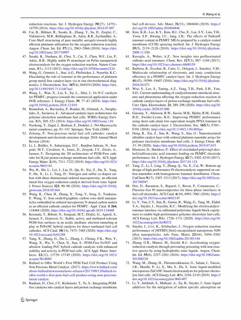
H. Wang et al.
1 3
reduction reactions. Int. J. Hydrogen Energy 39(27), 14751–14759 (2014). https:// doi. org/ 10. 1016/j. ijhyd ene. 2014. 07. 097
46. Cai, B., Hübner, R., Sasaki, K., Zhang, Y., Su, D., Ziegler, C., Vukmirovic, M.B., Rellinghaus, B., Adzic, R.R., Eychmüller, A.: Core-Shell structuring of pure metallic aerogels towards highly efficient platinum utilization for the oxygen reduction reaction. Angew. Chem. Int. Ed. 57(11), 2963–2966 (2018). https:// doi. org/ 10. 1002/ anie. 20171 0997
47. Sasaki, K., Naohara, H., Choi, Y., Cai, Y., Chen, W.F., Liu, P., Adzic, R.R.: Highly stable Pt monolayer on PdAu nanoparticle electrocatalysts for the oxygen reduction reaction. Nature Com-mun. 3(1), 1115 (2012). https:// doi. org/ 10. 1038/ ncomm s2124
48. Wang, G., Osmieri, L., Star, A.G., Pfeilsticker, J., Neyerlin, K.C.: Elucidating the role of ionomer in the performance of platinum group metal-free catalyst layer via in situ electrochemical diag-nostics. J. Electrochem. Soc. 167(4), 044519 (2020). https:// doi. org/ 10. 1149/ 1945- 7111/ ab7aa1
49. Wang, L., Wan, X., Liu, S., Xu, L., Shui, J.: Fe-N-C catalysts for PEMFC: progress towards the commercial application under DOE reference. J. Energy Chem. 39, 77–87 (2019). https:// doi. org/ 10. 1016/j. jechem. 2018. 12. 019
50. Bonnefont, A., Ruvinskiy, P., Rouhet, M., Orfanidi, A., Neophy-tides, S., Savinova, E.: Advanced catalytic layer architectures for polymer electrolyte membrane fuel cells. WIREs Energy Envi-ron. 3(5), 505–521 (2014). https:// doi. org/ 10. 1002/ wene. 110
51. Nyokong, T., Zagal, J., Bedioui, F., Dodelet, J.: N4-Macrocyclic metal complexes, pp. 83–147. Springer, New York (2006)
52. Zelenay, P.: Non-precious metal fuel cell cathodes: catalyst development and electrode structure design. 2016 Annual Merit Review (2016)
53. Li, J., Brüller, S., Sabarirajan, D.C., Ranjbar-Sahraie, N., Sou-grati, M.T., Cavaliere, S., Jones, D., Zenyuk, I.V., Zitolo, A., Jaouen, F.: Designing the 3D architecture of PGM-Free cath-odes for H2/air proton exchange membrane fuel cells. ACS Appl. Energy Mater. 2(10), 7211–7222 (2019). https:// doi. org/ 10. 1021/ acsaem. 9b011 81
54. Wu, H., Shi, L., Lei, J., Liu, D., Qu, D., Xie, Z., Du, X., Yang, P., Hu, X., Li, J., Tang, H.: Nitrogen and sulfur co-doped car-bon with three-dimensional ordered macroporosity: an efficient metal-free oxygen reduction catalyst derived from ionic liquid. J. Power Sources 323, 90–96 (2016). https:// doi. org/ 10. 1016/j. jpows our. 2016. 05. 044
55. Wang, K., Chen, H., Zhang, X., Tong, Y., Song, S., Tsiakaras, P., Wang, Y.: Iron oxide@graphitic carbon core-shell nanopar-ticles embedded in ordered mesoporous N-doped carbon matrix as an efficient cathode catalyst for PEMFC. Appl. Catal. B 264, 118468 (2020). https:// doi. org/ 10. 1016/j. apcatb. 2019. 118468
56. Kosmala, T., Bibent, N., Sougrati, M.T., Dražić, G., Agnoli, S., Jaouen, F., Granozzi, G.: Stable, active, and methanol-tolerant PGM-free surfaces in an acidic medium: electron tunneling at play in Pt/FeNC hybrid catalysts for direct methanol fuel cell cathodes. ACS Catal. 10(14), 7475–7485 (2020). https:// doi. org/ 10. 1021/ acsca tal. 0c012 88
57. Yang, X., Zhang, G., Du, L., Zhang, J., Chiang, F.K., Wen, Y., Wang, X., Wu, Y., Chen, N., Sun, S.: PGM-Free Fe/N/C and ultralow loading Pt/C hybrid cathode catalysts with enhanced stability and activity in PEM fuel cells. ACS Appl. Mater. Inter-faces. 12(12), 13739–13749 (2020). https:// doi. org/ 10. 1021/ acsami. 9b180 85
58. Ballard to Offer World’s First PEM Fuel Cell Product Using Non Precious Metal Catalyst. (2017). https:// www. balla rd. com/ about- balla rd/ newsr oom/ news- relea ses/ 2017/ 09/ 13/ balla rd- to- offer- world-s- first- pem- fuel- cell- produ ct- using- non- preci ous- metal- catal yst.
59. Banham, D., Choi, J.Y., Kishimoto, T., Ye, S.: Integrating PGM-free catalysts into catalyst layers and proton exchange membrane
fuel cell devices. Adv. Mater. 31(31), 1804846 (2019). https:// doi. org/ 10. 1002/ adma. 20180 4846
60. Kim, K.H., Lee, K.Y., Kim, H.J., Cho, E., Lee, S.Y., Lim, T.H., Yoon, S.P., Hwang, I.C., Jang, J.H.: The effects of Nafion® ionomer content in PEMFC MEAs prepared by a catalyst-coated membrane (CCM) spraying method. Int. J. Hydrogen Energy 35(5), 2119–2126 (2010). https:// doi. org/ 10. 1016/j. ijhyd ene. 2009. 11. 058
61. Kusoglu, A., Weber, A.Z.: New insights into perfluorinated sulfonic-acid ionomers. Chem. Rev. 117(3), 987–1104 (2017). https:// doi. org/ 10. 1021/ acs. chemr ev. 6b001 59
62. Barbosa, R., Escobar, B., Cano, U., Ortegon, J., Sanchez, V.M.: Multiscale relationship of electronic and ionic conduction efficiency in a PEMFC catalyst layer. Int. J. Hydrogen Energy 41(42), 19399–19407 (2016). https:// doi. org/ 10. 1016/j. ijhyd ene. 2016. 04. 071
63. Woo, S., Lee, S., Taning, A.Z., Yang, T.H., Park, S.H., Yim, S.D.: Current understanding of catalyst/ionomer interfacial struc-ture and phenomena affecting the oxygen reduction reaction in cathode catalyst layers of proton exchange membrane fuel cells. Curr. Opin. Electrochem. 21, 289–296 (2020). https:// doi. org/ 10. 1016/j. coelec. 2020. 03. 006
64. Garsany, Y., Atkinson, R.W., Sassin, M.B., Hjelm, R.M., Gould, B.D., Swider-Lyons, K.E.: Improving PEMFC performance using short-side-chain low-equivalent-weight PFSA lonomer in the cathode catalyst layer. J. Electrochem. Soc. 165(5), F381–F391 (2018). https:// doi. org/ 10. 1149/2. 13618 05jes
65. Deng, R., Xia, Z., Sun, R., Wang, S., Sun, G.: Nanostructured ultrathin catalyst layer with ordered platinum nanotube arrays for polymer electrolyte membrane fuel cells. J. Energy Chem. 43, 33–39 (2020). https:// doi. org/ 10. 1016/j. jechem. 2019. 07. 015
66. Ebenezer, D., Haridoss, P.: Effect of crosslinked poly(vinyl alco-hol)/sulfosuccinic acid ionomer loading on PEMFC electrode performance. Int. J. Hydrogen Energy 42(7), 4302–4310 (2017). https:// doi. org/ 10. 1016/j. ijhyd ene. 2017. 01. 124
67. Yang, Z., Li, J., Ling, Y., Zhang, Q., Yu, X., Cai, W.: Bottom-up design of high-performance Pt electrocatalysts supported on car-bon nanotubes with homogeneous lonomer distribution. Chem-CatChem 9(17), 3307–3313 (2017). https:// doi. org/ 10. 1002/ cctc. 20170 0587
68. Dru, D., Baranton, S., Bigarré, J., Buvat, P., Coutanceau, C.: Fluorine-free Pt nanocomposites for three-phase interfaces in fuel cell electrodes. ACS Catal. 6(10), 6993–7001 (2016). https:// doi. org/ 10. 1021/ acsca tal. 6b021 45
69. Li, Y., Van, C.T., Sun, R., Gawas, R., Wang, G., Tang, M., Elabd, Y.A., Snyder, J., Neyerlin, K.C.: Modifying the electrocatalyst–ionomer interface via sulfonated poly(ionic liquid) block copoly-mers to enable high-performance polymer electrolyte fuel cells. ACS Energy Lett. 5(6), 1726–1731 (2020). https:// doi. org/ 10. 1021/ acsen ergyl ett. 0c005 32
70. Snyder, J., Livi, K., Erlebacher, J.: Oxygen reduction reaction performance of [MTBD] [beti]-encapsulated nanoporous NiPt alloy nanoparticles. Adv. Func. Mater. 23(44), 5494–5501 (2013). https:// doi. org/ 10. 1002/ adfm. 20130 1144
71. Zhang, G.R., Munoz, M., Etzold, B.J.: Accelerating oxygen-reduction catalysts through preventing poisoning with non-reac-tive species by using hydrophobic ionic liquids. Angew. Chem. Int. Ed. 55(6), 2257–2261 (2016). https:// doi. org/ 10. 1002/ anie. 20150 8338
72. Wang, M., Zhang, H., Thirunavukkarasu, G., Salam, I., Varcoe, J.R., Mardle, P., Li, X., Mu, S., Du, S.: Ionic liquid-modified microporous ZnCoNC-based electrocatalysts for polymer electro-lyte fuel cells. ACS Energy Lett. 4(9), 2104–2110 (2019). https:// doi. org/ 10. 1021/ acsen ergyl ett. 9b014 07
73. Li, Y., Intikhab, S., Malkani, A., Xu, B., Snyder, J.: Ionic liquid additives for the mitigation of nafion specific adsorption on

Cathode Design for Proton Exchange Membrane Fuel Cells in Automotive Applications
1 3
platinum. ACS Catal. 10(14), 7691–7698 (2020). https:// doi. org/ 10. 1021/ acsca tal. 0c012 43
74. Mack, F., Klages, M., Scholta, J., Jörissen, L., Morawietz, T., Hiesgen, R., Kramer, D., Zeis, R.: Morphology studies on high-temperature polymer electrolyte membrane fuel cell elec-trodes. J. Power Sour. 255, 431–438 (2014). https:// doi. org/ 10. 1016/j. jpows our. 2014. 01. 032
75. Dowd, R.P., Li, Y., Van, N.T.: Controlling the ionic polymer/gas interface property of a PEM fuel cell catalyst layer dur-ing membrane electrode assembly fabrication. J. Appl. Elec-trochem. 50(10), 993–1006 (2020). https:// doi. org/ 10. 1007/ s10800- 020- 01453-w
76. Hou, Y., Deng, H., Pan, F., Chen, W., Du, Q., Jiao, K.: Pore-scale investigation of catalyst layer ingredient and structure effect in proton exchange membrane fuel cell. Appl. Energy 253, 113561 (2019). https:// doi. org/ 10. 1016/j. apene rgy. 2019. 113561
77. Wang, M., Park, J.H., Kabir, S., Neyerlin, K.C., Kariuki, N.N., Lv, H., Stamenkovic, V.R., Myers, D.J., Ulsh, M., Mauger, S.A.: Impact of catalyst ink dispersing methodology on fuel cell performance using in-situ X-ray scattering. ACS Appl. Energy Mater. 2(9), 6417–6427 (2019). https:// doi. org/ 10. 1021/ acsaem. 9b010 37
78. Yamada, H., Kato, H., Kodama, K.: Cell performance and dura-bility of Pt/C cathode catalyst covered by dopamine derived car-bon thin layer for polymer electrolyte fuel cells. J. Electrochem. Soc. 167(8), 084508 (2020). https:// doi. org/ 10. 1149/ 1945- 7111/ ab8b97
79. Zhou, F., Yan, Y., Guan, S., Guo, W., Sun, M., Pan, M.: Solv-ing nafion poisoning of ORR catalysts with an accessible layer: designing a nanostructured core-shell Pt/C catalyst via a one-step self-assembly for PEMFC. Int. J. Energy Res. 44(13), 10155–10167 (2020). https:// doi. org/ 10. 1002/ er. 5629
80. Orfanidi, A., Madkikar, P., El-Sayed, H.A., Harzer, G.S., Kratky, T., Gasteiger, H.A.: The key to high performance low Pt loaded electrodes. J. Electrochem. Soc. 164(4), F418–F426 (2017). https:// doi. org/ 10. 1149/2. 16217 04jes
81. Chen, M., Zhao, C., Sun, F., Fan, J., Li, H., Wang, H.: Research progress of catalyst layer and interlayer interface structures in membrane electrode assembly (MEA) for proton exchange membrane fuel cell (PEMFC) system. eTransportation 5, 100075 (2020). https:// doi. org/ 10. 1016/j. etran. 2020. 100075
82. Kim, Y.S., Welch, C.F., Mack, N.H., Hjelm, R.P., Orler, E.B., Hawley, M.E., Lee, K.S., Yim, S.D., Johnston, C.M.: Highly durable fuel cell electrodes based on ionomers dispersed in glycerol. Phys. Chem. Chem. Phys. 16(13), 5927–5932 (2014). https:// doi. org/ 10. 1039/ c4cp0 0496e
83. Jung, C.Y., Yi, S.C.: Improved polarization of mesoporous elec-trodes of a proton exchange membrane fuel cell using N-methyl-2-pyrrolidinone. Electrochim. Acta 113, 37–41 (2013). https:// doi. org/ 10. 1016/j. elect acta. 2013. 09. 041
84. Choo, M.J., Oh, K.H., Kim, H.T., Park, J.K.: Modulated ionomer distribution in the catalyst layer of polymer electrolyte membrane fuel cells for high temperature operation. Chemsuschem 7(8), 2335–2341 (2014). https:// doi. org/ 10. 1002/ cssc. 20140 2015
85. Kim, T.H., Yi, J.Y., Jung, C.Y., Jeong, E., Yi, S.C.: Solvent effect on the Nafion agglomerate morphology in the catalyst layer of the proton exchange membrane fuel cells. Int. J. Hydrogen Energy 42(1), 478–485 (2017). https:// doi. org/ 10. 1016/j. ijhyd ene. 2016. 12. 015
86. Karan, K.: PEFC catalyst layer: recent advances in materials, microstructural characterization, and modeling. Curr. Opin. Elec-trochem. 5(1), 27–35 (2017). https:// doi. org/ 10. 1016/j. coelec. 2017. 08. 018
87. Van, C.T., Khandavalli, S., Chowdhury, A., Medina, S., Pyl-ypenko, S., Wang, M., More, K.L., Kariuki, N., Myers, D.J.,
Weber, A.Z., Mauger, S.A., Ulsh, M., Neyerlin, K.C.: Dictat-ing Pt-based electrocatalyst performance in polymer electrolyte fuel cells, from formulation to application. ACS Appl. Mater. Interfaces. 11(50), 46953–46964 (2019). https:// doi. org/ 10. 1021/ acsami. 9b176 14
88. Lee, J., Liu, H., George, M.G., Banerjee, R., Ge, N., Chevalier, S., Kotaka, T., Tabuchi, Y., Bazylak, A.: Microporous layer to carbon fibre substrate interface impact on polymer electrolyte membrane fuel cell performance. J. Power Sour. 422, 113–121 (2019). https:// doi. org/ 10. 1016/j. jpows our. 2019. 02. 099
89. Wu, H.W.: A review of recent development: transport and perfor-mance modeling of PEM fuel cells. Appl. Energy 165, 81–106 (2016). https:// doi. org/ 10. 1016/j. apene rgy. 2015. 12. 075
90. Song, Y., Wei, Y., Xu, H., Williams, M., Liu, Y., Bonville, L.J., Russell, K., Fenton, H.: Improvement in high temperature proton exchange membrane fuel cells cathode performance with ammo-nium carbonate. J. Power Sour. 141(2), 250–257 (2005). https:// doi. org/ 10. 1016/j. jpows our. 2004. 09. 021
91. Kim, W.K., Sung, K.A., Oh, K.H., Choo, M.J., Cho, K.Y., Cho, K.Y., Park, J.K.: A new catalyst layer based on in situ pore gen-eration of sulfonated poly(ether ether ketone) for PEMFC. Elec-trochem. Commun. 11(8), 1714–1716 (2009). https:// doi. org/ 10. 1016/j. elecom. 2009. 07. 003
92. Harzer, G.S., Orfanidi, A., El-Sayed, H., Madkikar, P., Gasteiger, H.A.: Tailoring catalyst morphology towards high performance for low Pt loaded PEMFC cathodes. J. Electrochem. Soc. 165(10), F770–F779 (2018). https:// doi. org/ 10. 1149/2. 03118 10jes
93. Suzuki, T., Tsushima, S., Hirai, S.: Effects of Nafion® ionomer and carbon particles on structure formation in a proton-exchange membrane fuel cell catalyst layer fabricated by the decal-transfer method. Int. J. Hydrogen Energy 36(19), 12361–12369 (2011). https:// doi. org/ 10. 1016/j. ijhyd ene. 2011. 06. 090
94. Salari, S., Stumper, J., Bahrami, M.: Direct measurement and modeling relative gas diffusivity of PEMFC catalyst layers: The effect of ionomer to carbon ratio, operating temperature, poros-ity, and pore size distribution. Int. J. Hydrogen Energy 43(34), 16704–16718 (2018). https:// doi. org/ 10. 1016/j. ijhyd ene. 2018. 07. 035
95. Taghiabadi, M.M., Zhiani, M., Shafiei, M.: Influence of the cath-ode catalyst layer void volume on the short-term and long-term performance of PEM fuel cell. Fuel Cells 18(6), 731–741 (2018). https:// doi. org/ 10. 1002/ fuce. 20180 0023
96. Sassin, M.B., Garsany, Y., Atkinson, R.W., Hjelm, R.M., Swider-Lyons, K.E.: Understanding the interplay between cathode cata-lyst layer porosity and thickness on transport limitations en route to high-performance PEMFCs. Int. J. Hydrogen Energy 44(31), 16944–16955 (2019). https:// doi. org/ 10. 1016/j. ijhyd ene. 2019. 04. 194
97. Pournemat, A., Markötter, H., Wilhelm, F., Enz, S., Kropf, H., Manke, I., Scholta, J.: Nano-scale monte carlo study on liquid water distribution within the polymer electrolyte membrane fuel cell microporous layer, catalyst layer and their interfacial region. J. Power Sour. 397, 271–279 (2018). https:// doi. org/ 10. 1016/j. jpows our. 2018. 07. 027
98. Roh, C.W., Choi, J., Lee, H.: Hydrophilic-hydrophobic dual cata-lyst layers for proton exchange membrane fuel cells under low humidity. Electrochem. Commun. 97, 105–109 (2018). https:// doi. org/ 10. 1016/j. elecom. 2018. 11. 003
99. Oh, K.H., Kim, W.K., Sung, K.A., Choo, M.J., Nam, K.W., Choi, J.W., Park, J.K.: A hydrophobic blend binder for anti-water flood-ing of cathode catalyst layers in polymer electrolyte membrane fuel cells. Int. J. Hydrogen Energy 36(21), 13695–13702 (2011). https:// doi. org/ 10. 1016/j. ijhyd ene. 2011. 07. 116
100. Li, A., Chan, S.H., Nguyen, N.T.: Anti-flooding cathode cata-lyst layer for high performance PEM fuel cell. Electrochem.
H. Wang et al.
1 3
Commun. 11(4), 897–900 (2009). https:// doi. org/ 10. 1016/j. ele-com. 2009. 02. 022
101. Chi, B., Ye, Y., Lu, X., Jiang, S., Du, L., Zeng, J., Ren, J., Liao, S.: Enhancing membrane electrode assembly performance by improving the porous structure and hydrophobicity of the cath-ode catalyst layer. J. Power Sour. 443, 227–284 (2019). https:// doi. org/ 10. 1016/j. jpows our. 2019. 227284
102. Reshetenko, T.V., St-Pierre, J.: Separation method for oxygen mass transport coefficient in gas and ionomer phases in PEMFC GDE. J. Electrochem. Soc. 161(10), F1089–F1100 (2014). https:// doi. org/ 10. 1149/2. 10214 10jes
103. Jung, C.Y., Kim, S.K., Lee, S.J., Yi, S.C.: Three-dimensional reconstruction of coarse-dense dual catalyst layer for proton exchange membrane fuel cells. Electrochim. Acta 211, 142–147 (2016). https:// doi. org/ 10. 1016/j. elect acta. 2016. 06. 040
104. Suzuki, T., Nakata, Y., Tsutsui, F., Tsushima, S.: Investigation of gas transport properties of PEMFC catalyst layers using a micro-fluidic device. J. Electrochem. Soc. 167(12), 124519 (2020). https:// doi. org/ 10. 1149/ 1945- 7111/ abaf28
105. Shen, J., Zhou, J., Astrath, N.G., Navessin, T., Liu, Z.S., Lei, C., Rohling, J.H., Bessarabov, D., Knights, S., Ye, S.: Measurement of effective gas diffusion coefficients of catalyst layers of PEM fuel cells with a Loschmidt diffusion cell. J. Power Sour. 196(2), 674–678 (2011). https:// doi. org/ 10. 1016/j. jpows our. 2010. 07. 086
106. Middelman, E.: Improved PEM fuel cell electrodes by controlled self-assembly. Fuel Cells Bull. 2002(11), 9–12 (2002). https:// doi. org/ 10. 1016/ S1464- 2859(02) 11028-5
107. Lu, Y., Du, S., Steinberger-Wilckens, R.: One-dimensional nano-structured electrocatalysts for polymer electrolyte membrane fuel cells—a review. Appl. Catal. B 199, 292–314 (2016). https:// doi. org/ 10. 1016/j. apcatb. 2016. 06. 022
108. Wang, G., Zou, L., Huang, Q., Zou, Z., Yang, H.: Multidimen-sional nanostructured membrane electrode assemblies for proton exchange membrane fuel cell applications. J. Mater. Chem. A 7(16), 9447–9477 (2019). https:// doi. org/ 10. 1039/ C8TA1 2382A
109. Tian, Z.Q., Lim, S.H., Poh, C.K., Tang, Z., Xia, Z., Luo, Z., Shen, P.K., Chua, D., Feng, Y.P., Shen, Z., Lin, J.: A highly order-structured membrane electrode assembly with vertically aligned carbon nanotubes for ultra-low Pt loading PEM fuel cells. Adv. Energy Mater. 1(6), 1205–1214 (2011). https:// doi. org/ 10. 1002/ aenm. 20110 0371
110. Debe, M.K., Hendricks, S.M., Vernstrom, G.D., Meyers, M., Brostrom, M., Stephens, M., Chan, Q., Willey, J., Hamden, M., Mittelsteadt, C.K., Capuano, C.B., Ayers, K.E., Anderson, E.B.: Initial performance and durability of ultra-low loaded NSTF electrodes for PEM electrolyzers. J. Electrochem. Soc. 159(6), K165–K176 (2012). https:// doi. org/ 10. 1149/2. 06520 6jes
111. Chan, K., Eikerling, M.: Water balance model for polymer electrolyte fuel cells with ultrathin catalyst layers. Phys. Chem. Chem. Phys. 16(5), 2106–2117 (2014). https:// doi. org/ 10. 1039/ C3CP5 4849J
112. Jiang, S., Yi, B., Cao, L., Song, W., Zhao, Q., Yu, H., Shao, Z.: Development of advanced catalytic layer based on vertically aligned conductive polymer arrays for thin-film fuel cell elec-trodes. J. Power Sources 329, 347–354 (2016). https:// doi. org/ 10. 1016/j. jpows our. 2016. 08. 098
113. Xia, Z., Wang, S., Jiang, L., Sun, H., Liu, S., Fu, X., Zhang, B., Sheng, S.D., Wang, J., Sun, G.: Bio-inspired construction of advanced fuel cell cathode with Pt anchored in ordered hybrid polymer matrix. Sci. Rep. 5(1), 16100 (2015). https:// doi. org/ 10. 1038/ srep1 6100
114. Sun, R., Xia, Z., Shang, L., Fu, X., Li, H., Wang, S., Sun, G.: Hierarchically ordered arrays with platinum coated PANI nanow-ires for highly efficient fuel cell electrodes. J. Mater. Chem. A 5(29), 15260–15265 (2017). https:// doi. org/ 10. 1039/ C7TA0 2500A
115. Mardle, P., Ji, X., Wu, J., Guan, S., Dong, H., Du, S.: Thin film electrodes from Pt nanorods supported on aligned N-CNTs for proton exchange membrane fuel cells. Appl. Catal. B 260, 118031 (2020). https:// doi. org/ 10. 1016/j. apcatb. 2019. 118031
116. Rajalakshmi, N., Lakshmi, N., Dhathathreyan, K.S.: Nano tita-nium oxide catalyst support for proton exchange membrane fuel cells. Int. J. Hydrogen Energy 33(24), 7521–7526 (2008). https:// doi. org/ 10. 1016/j. ijhyd ene. 2008. 09. 032
117. Heinzl, C., Hengge, K.A., Perchthaler, M., Hacker, V., Scheu, C.: Insight into the degradation of HT-PEMFCs containing tungsten oxide catalyst support material for the anode. J. Electrochem. Soc. 162(3), F280–F290 (2014). https:// doi. org/ 10. 1149/2. 05415 03jes
118. Zhang, C., Yu, H., Li, Y., Fu, L., Gao, Y., Song, W., Shao, Z., Yi, B.: Highly stable ternary tin-palladium-platinum catalysts supported on hydrogenated TiO2 nanotube arrays for fuel cells. Nanoscale 5(15), 6834–6841 (2013). https:// doi. org/ 10. 1039/ c3nr0 1086d
119. Chen, M., Wang, M., Yang, Z., Wang, X.: High performance and durability of order-structured cathode catalyst layer based on TiO 2 @PANI core-shell nanowire arrays. Appl. Surf. Sci. 406, 69–76 (2017). https:// doi. org/ 10. 1016/j. apsusc. 2017. 01. 296
120. Jiang, S., Yi, B., Zhang, C., Liu, S., Yu, H., Shao, Z.: Vertically aligned carbon-coated titanium dioxide nanorod arrays on carbon paper with low platinum for proton exchange membrane fuel cells. J. Power Sour. 276, 80–88 (2015). https:// doi. org/ 10. 1016/j. jpows our. 2014. 11. 093
121. Du, S.: A facile route for polymer electrolyte membrane fuel cell electrodes with in situ grown Pt nanowires. J. Power Sour. 195(1), 289–292 (2010). https:// doi. org/ 10. 1016/j. jpows our. 2009. 06. 091
122. Du, S.: Pt-based nanowires as electrocatalysts in proton exchange fuel cells. Int. J. Low-Carbon Technol. 7(1), 44–54 (2012). https:// doi. org/ 10. 1093/ ijlct/ ctr027
123. Lu, Y., Du, S., Steinberger-Wilckens, R.: Three-dimensional cata-lyst electrodes based on PtPd nanodendrites for oxygen reduc-tion reaction in PEFC applications. Appl. Catal. B 187, 108–114 (2016). https:// doi. org/ 10. 1016/j. apcatb. 2016. 01. 019
124. Lu, Y., Du, S., Steinberger-Wilckens, R.: Temperature-controlled growth of single-crystal Pt nanowire arrays for high performance catalyst electrodes in polymer electrolyte fuel cells. Appl. Catal. B 164, 389–395 (2015). https:// doi. org/ 10. 1016/j. apcatb. 2014. 09. 040
125. Du, S., Lin, K., Malladi, S.K., Lu, Y., Sun, S., Xu, Q., Stein-berger-Wilckens, R., Dong, H.: Plasma nitriding induced growth of Pt-nanowire arrays as high performance electrocatalysts for fuel cells. Sci. Rep. 4, 6439 (2014). https:// doi. org/ 10. 1038/ srep0 6439
126. Yao, X., Su, K., Sui, S., Mao, L., He, A., Zhang, J., Du, S.: A novel catalyst layer with carbon matrix for Pt nanowire growth in proton exchange membrane fuel cells (PEMFCs). Int. J. Hydro-gen Energy 38(28), 12374–12378 (2013). https:// doi. org/ 10. 1016/j. ijhyd ene. 2013. 07. 037
127. Su, K., Yao, X., Sui, S., Wei, Z., Zhang, J., Du, S.: Matrix mate-rial study for in situ grown Pt nanowire electrocatalyst layer in proton exchange membrane fuel cells (PEMFCs). Fuel Cells 15(3), 449–455 (2015). https:// doi. org/ 10. 1002/ fuce. 20140 0168
128. Wei, Z., Su, K., Sui, S., He, A., Du, S.: High performance poly-mer electrolyte membrane fuel cells (PEMFCs) with gradient Pt nanowire cathodes prepared by decal transfer method. Int. J. Hydrogen Energy 40(7), 3068–3074 (2015). https:// doi. org/ 10. 1016/j. ijhyd ene. 2015. 01. 009
129. Sui, S., Wei, Z., Su, K., He, A., Wang, X., Su, Y., Hou, X., Raf-fet, S., Du, S.: Pt nanowire growth induced by Pt nanoparticles in application of the cathodes for polymer electrolyte mem-brane fuel cells (PEMFCs). Int. J. Hydrogen Energy 43(43),

Cathode Design for Proton Exchange Membrane Fuel Cells in Automotive Applications
1 3
20041–20049 (2018). https:// doi. org/ 10. 1016/j. ijhyd ene. 2018. 09. 009
130. Fidiani, E., Thirunavukkarasu, G., Li, Y., Chiu, Y.L., Du, S.: Ultrathin AgPt alloy nanorods as low-cost oxygen reduction reac-tion electrocatalysts in proton exchange membrane fuel cells. J. Mater. Chem. A 8(23), 11874–11883 (2020). https:// doi. org/ 10. 1039/ D0TA0 2748K
131. Mardle, P., Thirunavukkarasu, G., Guan, S., Chiu, Y.L., Du, S.: Comparative study of PtNi nanowire array electrodes toward oxy-gen reduction reaction by half-cell measurement and PEMFC test. ACS Appl. Mater. Interfaces. 12(38), 42832–42841 (2020). https:// doi. org/ 10. 1021/ acsami. 0c115 31
132. Marconot, O., Pauc, N., Buttard, D., Morin, A.: Vertically aligned platinum copper nanotubes as PEM fuel cell cathode: elaboration and fuel cell test. Fuel Cells 18(6), 723–730 (2018). https:// doi. org/ 10. 1002/ fuce. 20170 0242
133. Zeng, Y., Shao, Z., Zhang, H., Wang, Z., Hong, S., Yu, H., Yi, B.: Nanostructured ultrathin catalyst layer based on open-walled PtCo bimetallic nanotube arrays for proton exchange membrane fuel cells. Nano Energy 34, 344–355 (2017). https:// doi. org/ 10. 1016/j. nanoen. 2017. 02. 038
134. Shimpalee, S., Satjaritanun, P., Hirano, S., Tippayawong, N., Weidner, J.W.: Multiscale modeling of PEMFC using co-simu-lation approach. J. Electrochem. Soc. 166(8), F534–F543 (2019). https:// doi. org/ 10. 1149/2. 02919 11jes
135. Conde, J.J., Folgado, M.A., Ferreira-Aparicio, P., Chaparro, A.M., Chowdhury, A., Kusoglu, A., Cullen, D., Weber, A.Z.: Mass-transport properties of electrosprayed Pt/C catalyst layers for polymer-electrolyte fuel cells. J. Power Sour. 427, 250–259 (2019). https:// doi. org/ 10. 1016/j. jpows our. 2019. 04. 079
136. Zhang, D., Cai, Q., Gu, S.: Three-dimensional lattice-Boltzmann model for liquid water transport and oxygen diffusion in cathode of polymer electrolyte membrane fuel cell with electrochemical reaction. Electrochim. Acta 262, 282–296 (2018). https:// doi. org/ 10. 1016/j. elect acta. 2017. 12. 189
137. Ramaswamy, N., Kumaraguru, S.: Materials and design selection to improve high current density performance in PEMFC. ECS Trans. 85(13), 835–842 (2018). https:// doi. org/ 10. 1149/ 08513. 0835e cst
138. Zhu, F., Luo, L., Wu, A., Wang, C., Cheng, X., Shen, S., Ke, C., Yang, H., Zhang, J.: Improving the high-current-density perfor-mance of PEMFC through much enhanced utilization of platinum
electrocatalysts on carbon. ACS Appl. Mater. Interfaces. 12(23), 26076–26083 (2020). https:// doi. org/ 10. 1021/ acsami. 0c069 81
139. Lee, H.Y., Kim, S.K., Lee, M.R., Peck, D.H., Kang, Y.C., Kim, C.S.: Reduced mass transport resistance in polymer electrolyte membrane fuel cell by polyethylene glycol addition to catalyst ink. Int. J. Hydrogen Energy 44(1), 354–361 (2019). https:// doi. org/ 10. 1016/j. ijhyd ene. 2018. 08. 134
140. Wang, Y., Seo, B., Wang, B., Zamel, N., Jiao, K., Adroher, X.C.: Fundamentals, materials, and machine learning of polymer elec-trolyte membrane fuel cell technology. Energy and AI 1, 100014 (2020). https:// doi. org/ 10. 1016/j. egyai. 2020. 100014
141. Whiston, M.M., Azevedo, I.L., Litster, S., Whitefoot, K.S., Samaras, C., Whitacre, J.F.: Expert assessments of the cost and expected future performance of proton exchange membrane fuel cells for vehicles. Proc. Natl. Acad. Sci. 116(11), 4899–4904 (2019). https:// doi. org/ 10. 1073/ pnas. 18042 21116
142. Yumiya, H., Kizaki, M., Asai, H.: Toyota fuel cell system (TFCS). World Electric Vehicle Journal 7(1), 85–92 (2015). https:// doi. org/ 10. 3390/ wevj7 010085
143. Lohse-Busch, H., Stutenberg, K., Duoba, M., Iliev, S.: Tech-nology assessment of a fuel cell vehicle:2017 Toyota Mirai. Argonne National Lab (ANL), Argonne (2018)
144. Volume Manufacturing of PEM FC Stacks for Transportation and In-line Quality Assurance. (2019). https:// cordis. europa. eu/ proje ct/ id/ 671465.
145. DOE Technical Targets for Fuel Cell Systems and Stacks for Transportation Applications. (2020). https:// www. energy. gov/ eere/ fuelc ells/ doe- techn ical- targe ts- fuel- cell- syste ms- and- stacks- trans porta tion- appli catio ns.
146. STATE-OF-THE-ART AND FUTURE TARGETS(KPIS). (2020). https:// www. fch. europa. eu/ soa- and- targe ts.
147. Kurtz, J.M., Sprik, S., Saur, G., Onorato, S.: Fuel cell electric vehicle durability and fuel cell performance. National Renewable Energy Lab, United States (2019)
148. Strategy for Developing Hydrogen and Fuel-Cell Technologies Formulated. (2019). https:// www. meti. go. jp/ engli sh/ press/ 2019/ 0918_ 001. html.
149. Du, S.: Recent advances in electrode design based on one-dimen-sional nanostructure arrays for proton exchange membrane fuel cell applications. Engineering (2020). https:// doi. org/ 10. 1016/j. eng. 2020. 09. 014