caterpillar performance handbook · geographic versions — cat motor graders were spe- ... 160,...
TRANSCRIPT
© 2014 Caterpillar. All Rights Reserved. CAT, CATERPILLAR, BUILT FOR IT, their respective logos, “Caterpillar Yellow,” the “Power Edge” trade dress as well as corporate and product identity used herein, are trademarks of Caterpillar and may not be used without permission.
800.437.4228www.hawthornecat.com
Caterpillar® Performance
Handbook Edition 44
MOTOR GRADERS

11
Edition 44 11-1
CONTENTSIndustries Served . . . . . . . . . . . . . . . . . . . . . . . . . . . 11-1Features . . . . . . . . . . . . . . . . . . . . . . . . . . . . . . . . . . 11-2Applications. . . . . . . . . . . . . . . . . . . . . . . . . . . . . . . 11-6Specifications: Standard Versions . . . . . . . . . . . . . . 11-9Specifications: Global Versions. . . . . . . . . . . . . . .11-12Travel Speeds . . . . . . . . . . . . . . . . . . . . . . . . . . . . .11-18All Wheel Drive (AWD) . . . . . . . . . . . . . . . . . . . .11-20Mid Mount and Front Mount Scarifiers . . . . . . .11-20Rear Ripper and Rear Ripper Scarifier . . . . . . . .11-21Production . . . . . . . . . . . . . . . . . . . . . . . . . . . . . . .11-25Formulas . . . . . . . . . . . . . . . . . . . . . . . . . . . . . . . .11-27Extreme Slope Operation . . . . . . . . . . . . . . . . . . .11-28Work Tools. . . . . . . . . . . . . . . . . . . . . . . . . . . . . . .11-29
INDUSTRIES SERVEDThe motor grader is one of the most versatile work tools
in the Cat® product line. The M Series machines are used in numerous applications within a wide range of indus-tries. The major industries using Cat motor graders, along with the typical applications within each, are sum-marized below.
● Heavy Construction Highway Construction
Paving/ResurfacingAirport ConstructionRailroad ConstructionDam and Levee ConstructionHaul Road Maintenance
● Governmental Road Maintenance
Road ConstructionDitch Building/CleaningSnow Removal
● Building Construction Residential Construction
Commercial ConstructionIndustrial ConstructionSewer and Water Systems
● Industrial Waste Disposal
Pipeline Construction
● Mining Haul Road Maintenance
Snow Removal
● Forestry Access Road Construction
Forest DevelopmentSnow RemovalHaul Road Maintenance
● Geographic Versions — Cat Motor Graders were spe-cif ically designed to meet the needs of dif ferent geo-graphic regions and regulations. K/K2 Series for less regulated locations and M/M2/M3 Series are avail able with an assortment of standard features and optional equip ment. All motor graders feature advanced elec-tron ically con trolled Cat engines, power train com po-nents, hydraulics and machine structures.
MOTOR GRADERS
PHB-Sec11-14.indd 1PHB-Sec11-14.indd 1 12/20/13 8:36 AM12/20/13 8:36 AM

FEATURES, M Series Motor Graders:Building on the strong heritage of the H Series, the
M Series delivers multiple technological breakthroughs, setting the new standard for motor graders. The H Series has been the industry standard in a variety of heavy construc tion, mining, road building and governmental appli cations. The M Series continues this tradition, incor porating revolutionary, customer-driven enhance-ments by:
– Improving ease of operation and operation train ing time
– Offering best-in-class operator station and un matched visibility
– Delivering maximum productivity– Improving availability and decreasing maintenance
time
The M Series line includes eight models: 120, 12, 140, 140 AWD, 160, 14, 16, 24. The 120M through 14M meet construction, road building, and governmental appli cations. The 140M All Wheel Drive model improves traction in poor underfoot conditions such as snow, mud, and sand. The 16M and 24M meet the specialized needs of large mining customers.
● Operation Station: The 120M through 16M models fea ture a revolutionary cab design that provides unmatched comfort, visibility and ease of use, which can enhance operator confidence and productivity. The M Series provides a comfortable environment to keep the operator alert and focused. The interior noise level is maintained between 70 and 74 dB(A) with the doors and windows closed.
Ease of Operation. The revolutionary joystick con-trols and exceptional visibility make the M Series easier to operate without sacrificing control. The intuitive joy stick control pattern allows both new and expe ri-enced operators to become productive quickly. Logical grouping of hydraulic functions in the joysticks allow any operator to easily control several functions at the same time. This allows the operator to be more pro-duc tive and remain comfortable throughout the work shift.
Advanced Joystick Controls. Two electro-hydraulic joysticks reduce hand and wrist movement as much as 78% compared to conventional lever controls for greatly enhanced operator efficiency. The intuitive pattern is easy to learn and provides the precise imple-ment control to allow both new and experienced oper-ators to become productive quickly. Logical group ing of hydraulic functions in the joysticks allow any oper-ator to control several functions at the same time for more productivity.
Visibility. The 120M through 16M models boast excel-lent visibility to the work area, made possible with angled cab doors, a tapered engine enclosure and a patented sloped rear window. Ample glass area and carefully placed components provide excellent visi-bility to enhance operator confidence and produc-tivity in all motor grader applications. The M Series gives the operator an exceptional view forward to the blade, working surface and front tires. The M Series black glare-reducing paint on the front frame and engine enclosure enhances visibility.
● Drawbar, Circle and Moldboard: The 120M through 16M models provide a broad range of extended blade positions particularly beneficial in mid-range bank sloping, ditch cutting and ditch cleaning. A long wheel base allows for an aggressive blade angle permitting material to roll more freely, reducing power requirements. Top-accessible drawbar wear inserts and the shimless mold board retention system make DCM adjustments fast and simple, delivering more precise material control while lowering operating costs.
Top-Adjust Drawbar Wear Strips. The patented top-adjust wear strips dramatically reduce drawbar/circle adjustment time. By removing the access plates on top of the drawbar, shims and wear strips can easily be added or replaced. This feature reduces service down-time and lowers overall machine operating costs.
Shimless Moldboard Retention System. The unique shimless moldboard retention system reduces the potential for blade chatter. Adjusting screws keep the moldboard’s wear strips aligned for precise blade control and dramatic reductions in service time.
11-2 Edition 44
Motor Graders Features
PHB-Sec11-14.indd 2PHB-Sec11-14.indd 2 12/20/13 8:36 AM12/20/13 8:36 AM

11
Edition 44 11-3
● Power Train: Integrated, electronically controlled systems, deliver smooth reliable performance with reduced operating costs.
Smooth Shifting Transmission. The M Series com-bines several key innovations to ensure smooth, power ful shifts throughout the gear range.
Electronically Controlled Shifting. The full Elec tronic Clutch Pressure Control (ECPC) system optimizes inching modulation and smoothes shifting between all gears and directional changes. This provides out-standing control and also extends the life of the trans-mission by reducing stress on gears.
Load Compensation. This standard feature ensures consistent shift quality regardless of blade or machine load.
Hydraulic Brakes. The oil bathed, multi-disc ser vice brakes are hydraulically actuated, providing smooth predictable braking and lower operating costs. With brakes located at each tandem wheel, the M Series offer the largest total brake surface area in the indus-try, delivering dependable stopping power and longer brake life.
● Engine: The M Series combines power management with ACERT™ Technology to deliver maximum power and efficiency while reducing the environmental impact.
ACERT Technology. ACERT Technology allows Cat engines to supply more power per unit of dis place-ment without causing premature wear. This break-through technology reduces emissions during the combustion process by using advanced technol ogy in the air and fuel systems, in conjunc tion with inte grated electronics. ACERT Tech nology enhances over all engine performance while dramatically reduc ing exhaust emissions.
Power Management. The M Series Power Man age-ment System automatically delivers an additional 3.7 kW (5 hp) in each forward gear 1st through 4th, and each reverse gear 1st through 3rd. This standard feature optimizes rimpull for all gears by balancing traction, speed and horsepower while conserving fuel. The system limits horsepower in lower gears, which helps reduce wheel slip where traction is limited. With Variable Horsepower Plus (VHP Plus), an addi tional 3.7 kW (5 hp) is delivered in each forward gear 5th through 8th for more power at higher speeds.
Exhaust Emission Standards. The Cat ACERT Tech-nology engines in the M Series Motor Graders emit at levels equivalent to U.S. EPA Tier 3 and European Union Stage IIIA emission standards. The M2 Series machines meet all U.S. EPA Tier 4 Interim and Euro pean Union Stage IIIB emission standards. The M3 Series machines meet U.S. EPA Tier 4 Final emission standards.
● Hydraulics: The M Series electro-hydraulics enable advanced machine controls with precise and predict-able movements.
Advanced Electro-Hydraulic System. The M Series incorporates a state-of-the-art electro-hydraulic system. This technology is the foundation for revolutionary changes of the machine and implement controls. Advanced joystick controls provide unmatched con-troll ability with precise, predictable hydraulic move-ments and the reliability you expect from Cat products.
Load Sensing Hydraulics (PPPC). The time proven load-sensing system and the advanced Proportional Priority Pressure-Compensating (PPPC, or “triple- PC”) electro-hydraulic valves on the M Series are designed to provide superior implement control and enhanced machine performance in all applications. Continuous match ing of hydraulic flow and pressure to power de mands creates less heat and reduces power consumption.
Motor GradersFeatures
PHB-Sec11-14.indd 3PHB-Sec11-14.indd 3 12/20/13 8:36 AM12/20/13 8:36 AM

● Serviceability:
Grouped Service Points. The M Series groups daily ser-vice points in the left side service center to help ensure proper maintenance and inspection routines.
Extended Service Intervals. The M Series extended service intervals, such as 500-hour engine oil changes and 4000-hour hydraulic oil changes, reduce machine service time and increase availability.
Ecology Drains. Conveniently located ecology drains shorten service times and help keep the environment safe by preventing spills.
Diagnostics and Monitoring. The M Series pro vides Cat Messenger as standard equipment to enhance diagnostic capabilities by displaying machine system errors and fault codes. Cat Elec tronic Technician is a two way communication tool that provides easy access to stored diagnostic data and lets technicians config-ure machine parameters through the Cat Data Link. Product Link™ provides a communication flow of vital machine data and location. The M Series integrates Cat Messenger, Cat Electronic Technician, and S•O•SSM analysis for easy monitoring and fast trouble shoot-ing, keep ing your machine up and running.
● Safety. Safety is an integral part of all machine and system designs. The M Series machines provide a safe working environment for both the operator and ground personnel. ROPS and FOPS structures meet-ing current SAE and ISO requirements are standard on all Global machines. Back-up alarms are also stan-dard on the M Series.
Operator Presence System. The Operator Pre sence System keeps the parking brake engaged until the operator is seated for safe operation.
Secondary Steering System. The standard secondary steering system automatically engages in case of a drop in steering pressure, allowing the operator to steer the machine to a stop.
Speed Sensitive Steering. The steering software auto-matically provides an infinitely variable ratio between the joystick and the steer tires, resulting in less sensitive steering as the groundspeed increases.
Hydraulic Lockout. A simple switch located in the cab disables all implement functions while still pro-viding machine steering control. This safety feature is especially useful while the machine is roading.
Circle Drive Slip Clutch. This standard feature pro-tects the drawbar, circle and moldboard from shock loads when the end of the blade encounters immov-able objects. It also reduces the possibility of abrupt directional changes in poor traction conditions, pro-tecting the machine, operator and surroundings.
Blade Lift Accumulators. This optional feature uses accumulators to help absorb impact loads to the moldboard by allowing vertical blade travel. Blade lift accumulators reduce unnecessary wear and help to avoid unintended machine movement for increased operator safety.
Drop-Down Rear Lights. Optional drop-down lights fold out from the rear of the machine. This creates a wider, lower profile, to be better aligned with passen-ger cars.
Rearview Camera. Visibility is further enhanced with an optional Work Area Vision System (WAVS) LCD color monitor in the cab.
● Automatic Differential Lock/Unlock. The Auto Diff-Lock feature automatically unlocks the differential during a turn, re-locks when straight, for easier opera-tion and improved power train protection.
● Swing Out Cooling Fan. This standard feature allows for easy access to the cooling cores reducing time required for clean out. The latched door requires no tools for opening and closing. Note: M2/M3 Series only.
11-4 Edition 44
Motor Graders Features
PHB-Sec11-14.indd 4PHB-Sec11-14.indd 4 12/20/13 8:36 AM12/20/13 8:36 AM
11
Edition 44 11-5
Motor GradersFeatures
FEATURES, K Series Motor Graders:
OverviewThe K Series model line-up is targeted to meet cus-
tomer requirements in less regulated countries. Built on the success of the Standard H Series, the K Series deliv-ers multiple improvements in emissions control and operator features, while still maintaining the industry standard for reliability. The K Series model line up con-sists of the 120K, 120K2, 12K, 140K, 140K2, and 160K.
Engine● ACERT Engine Technology: The K Series models are
equipped with Cat ACERT engine technology, which uses numerous advanced components to efficiently produce more power and fewer emissions.
● Emissions: The K Series machines emit at levels equivalent to U.S. EPA Tier 2 and EU Stage II emis-sion standards. The K Series 2 machines are certified to Bharat Stage III and China Stage II emission standards.
● Power Management Strategy: The K Series power management strategy provides an additional 7.5 kW (10 hp) increase in third and another 7.5 kW (10 hp) in fourth gear through Variable Horsepower (VHP). This allows the operator to main tain maximum rim-pull while increasing ground speed and productivity.
Power Train● Electronic Clutch Pressure Control (ECPC): This stan-
dard K Series feature smoothes shifts and improves inching control. The system uses input from the transmission and operator controls to modulate the directional clutches and produce consistent shifting.
● Autoshift: This optional feature improves ease of operation and maximizes productivity by auto mat-ically shifting the transmission at optimal shifting points.
Serviceability● Grouped Service Points: The K Series groups daily
service points in the left side service center to help ensure proper maintenance and inspection routines.
● Diagnostic Capability: The K Series offers an improved dash cluster to keep the operator informed of critical system conditions. Cat Electronic Techni cian is also offered, allowing faster diagnostic capabilities by service personnel. Product Link allows tracking of vital machine data and location, providing a con ve-nient way to track the machine.
● Extended Service Intervals: Improvements in ser vice-ability allow increased machine operation between ser vice intervals. The machines can operate a full 500 hours between engine oil and filter changes, 4,000 hours between hydraulic oil changes, and 12,000 hours between engine coolant changes. This reduces downtime and operating expense.
PHB-Sec11-14.indd 5PHB-Sec11-14.indd 5 12/20/13 8:36 AM12/20/13 8:36 AM

APPLICATIONS, Motor Graders:The broad line of Cat Motor Graders allows the
cus tomer to choose a motor grader that best fits the intended application. Below is a summary of the typical motor grader applications.
Finish GradingThis application involves preparing a roadway or site
surface for future paving or other construction activity. The material being moved is usually a hard, dry base material on a solid underfoot. Finish blading is the motor grader application that requires the highest degree of accuracy. Thus, it is primarily done at low operating speeds — usually less than 5 km/h (3 mph) — in gears 1 and 2. To ensure a smooth, even finished surface, one gear is usually maintained for a given pass. Pass lengths during this application are usually less than 600 m (2000 feet) for road construction and 150 m (500 feet) for site development. Most finish blading is performed by contractors in the Heavy Construction and Building Con struc tion industries.
Heavy BladingThis application involves cutting, moving, and mix ing
material, usually in the initial stages of surface prep a ra-tion. A variety of material types are moved in this man-ner, and the blade tip position varies accord ing ly. Full blade loads are usually experienced during heavy blad ing, since moving material is the primary goal. Pass lengths within this application vary, but are usually less than 600 m (2000 feet). Unlike finish blad ing, the speed of the machine is dependent on the load being moved when heavy blading material. Typical operating speeds are from 0-10 km/h (0 to 6 mph). There fore, gears 2 through 4 are frequently used in this appli ca tion. Most heavy blad-ing activ ity is performed by con tractors in the Heavy Con struc tion, Govern mental, Industrial, and Forestry industries.
Site PreparationThis application involves any material cutting, mov-
ing, and mixing necessary to prepare a residential, com mercial, or industrial site for construction. A vari-ety of materials are encountered in this application. Blade loads vary depending on the activity being performed. Both heavy blading and finish blading are performed when preparing a site. Pass lengths are typically in the range of 30-300 m (100 to 1000 feet). Typical operating speeds for site preparation vary depending on whether heavy blading or finish blading activities are being per formed. Most site preparation activities are performed by contractors in the Building Construction industry.
Road MaintenanceThis application involves reshaping dirt or gravel
roads to maintain a crown or superelevation, or restor-ing the surface itself. This generally involves secondary roads maintained by governmental bodies such as townships and counties. Materials being moved in this application vary from extremely hard dirt bases to moist gravel surfaces. The typical blade load falls between that of finish blading and heavy blad ing. Pass lengths are fre quently longer than 600 m (2000 feet) and can extend for miles. The general speed range for this appli cation is 5-16 km/h (3 to 10 mph), corre spond-ing to gears 2 (heavy dirt) through 5 (soft gravel). As with finish blad ing, accuracy of the graded surface is the primary con cern in this application. Thus, frequent shifts should be avoided whenever possible. A gear should be chosen and main tained unless there is a sig-nif i cant change in the material being moved. Most road main tenance activ ities are performed by the Govern-mental industry.
11-6 Edition 44
Motor Graders Applications
PHB-Sec11-14.indd 6PHB-Sec11-14.indd 6 12/20/13 8:36 AM12/20/13 8:36 AM

11
Haul Road MaintenanceThis application of the motor grader involves reshap-
ing haul roads at mining, construction, or forestry work sites, usually for the purpose of maintaining smooth travel surfaces for equipment. Mate rials being moved while maintaining haul roads vary widely. Typical blade loads are about one-third to half of full capacity. Haul roads that experience large hauling units travel ling on soft material may require heavy blade loads in order to reshape the road surface. Pass lengths vary depending on the application but can extend for miles on remote forestry or large mine haul roads. The general speed range for haul road maintenance is heavily dependent on the material being moved as well as the grade of the haul road. Many mine sites are in mountainous areas, requiring haul roads with steep grades. Generally, haul-road maintenance is performed at speeds similar to those required for general road maintenance 5-16 km/h (3 to 10 mph).
A travel surface that allows for the safe and efficient movement of machinery is the ultimate goal with this motor grader application. Very precise road way eleva-tions and slopes are desired but less crucial than when finish blading. Most haul road maintenance activities are performed by the Mining, Heavy Construction, and Forestry industries.
Side/Bank Slope WorkThis application involves preparing side slopes or
bank slopes along roadways by placing the moldboard on a sloped surface. Slopes of up to a 2:1 angle can be cut using a motor grader. Often the motor grader is oper-ated on the level surface adjacent to the slope, and the moldboard is extended outward to the sloped sur face. Fine soils are generally encountered in this appli cation of the motor grader. Blade loads are usually less than half of the full blade capacity, and pass lengths are seldom longer than 600 m (2000 feet). A smooth-graded sloped surface is the primary concern in this application so frequent shifts should be avoided. The typical speed range is 0-6 km/h (0 to 4 mph), corre sponding to a gear selection of 1 to 3. The nominal speed is heavily depen-dent on the type of material being moved and on the slope of the surface. Most side/bank slope work is per-formed by the Heavy Construction and Governmental industries.
Ditch Building/CleaningThis application involves cutting “V” and flat-bottom
ditches for drainage purposes and rebuilding them when necessary. Due to excessive rain and/or poor material, ditches often need cleaning and reshaping. When build-ing ditches, materials with a wide range of densities are encountered. Blade loads vary accord ingly, from half to full-blade capacity. Pass lengths are usually less than 600 m (2000 feet). The primary objective is to move mate rial in a manner that yields a ditch with the desired slope. Ditch building often involves cutting and moving material of high density. Therefore, typical speed ranges vary. Most ditch build ing work, however, is performed in gears 1 through 3, corresponding to a maximum speed of about 8 km/h (5 mph). Ditch cleaning usually involves blading moist materials underneath a sod cover. Blade loads are usually less than half of full blade capacity when cleaning ditches, and pass lengths are similar to those encountered in ditch building. Typical maximum speeds for this activity are similar to that of ditch build-ing, but less of a blade load is experienced. Ditch building and cleaning activities are usually performed by the Heavy Construction and Governmental industries.
Edition 44 11-7
Motor GradersApplications
PHB-Sec11-14.indd 7PHB-Sec11-14.indd 7 12/20/13 8:36 AM12/20/13 8:36 AM

Ripping/ScarifyingThis application involves conditioning hard, rough
soils before they are bladed. Shanks on the ripper and/or scarifier are pushed into the ground, thus breaking up otherwise hard surfaces. Hard materials such as asphalt can also be loosened in order to make grading operations less damaging to the moldboard. Rippers and scarifiers can also be used to mix aggregates together. The materials being ripped/ scarified are usually hard and dry. Rippers generally penetrate 150-300 mm (6 to 12 inches) into the ground, while scarifiers typically penetrate to a depth of 25-200 mm (1 to 8 inches). Pass lengths are generally less than 600 m (2000 feet) for both activities. Since the material being ripped/scarified is generally hard, the typical maximum speed for this application is about 6 km/h (4 mph) gears 1-2. If the ripper/scarifier is used for mixing aggregates, the typical operating range becomes 6-20 km/h (4 to 12 mph) gears 3-6. Most ripping/scarifying activities are performed by the Heavy Construction and Governmental industries.
Snow RemovalSnow removal is the process of cutting and removing
snow or ice from the roadway. In addition to the stan-dard motor grader moldboard, other attachments such as a snow wing, V-plow, one-way plow, or reversible plow can be used to remove the snow. The moldboard itself is the most commonly used attachment for snow plowing. It is used in areas where snow depths are low, the terrain is relatively flat, and where excessive drifting does not occur. A snow wing is a moldboard that attaches to the machine’s right side. The wing’s curvature lifts the snow and “wings” it off the plowed surface. The snow wing is often used in conjunction with the stan-dard moldboard, where the moldboard cuts the mate-rial and feeds it onto the wing. V-plows are mounted in front of the motor grader and are designed to dig into and lift packed snow. The typical speed range for snow removal is 10-30 km/h (6 to 18 mph), corresponding to a gear range of 3 to 7. Snow plowing often involves lower speeds than snow removal. The typical operating range for snow plowing is 8-19 km/h (5 to 12 mph) gears 2 to 4. The majority of Snow Removal/Plowing operations are performed by the Governmental, Mining, and Forestry industries.
11-8 Edition 44
Motor Graders Applications
PHB-Sec11-14.indd 8PHB-Sec11-14.indd 8 12/20/13 8:36 AM12/20/13 8:36 AM

Edition 44 11-9
11
MODEL 120K 12KNet Flywheel Power: Gears 4-8 108 kW 145 hp 123 kW 165 hpNet Flywheel Power: Gear 3▲ 101 kW 135 hp 116 kW 155 hpNet Flywheel Power: Gears 1-2▲ 93 kW 125 hp 108 kW 145 hpOperating Weight (Typical)* 13 843 kg 30,519 lb 14 308 kg 31,543 lbEngine Model C7 ACERT VHP C7 ACERT VHPRated Engine RPM 2000 2000No. of Cylinders 6 6Displacement 7.2 L 439 in3 7.2 L 439 in3
Max. Torque 774 N·m 571 lb-ft 881 N·m 650 lb-ftNo. of Speeds Forward/Reverse 8/6 8/6Top Speed: Forward 47.5 km/h 29.5 mph 46.6 km/h 29.0 mphTop Speed: Reverse 37.5 km/h 23.3 mph 36.8 km/h 22.9 mphStd. Tires — Front and Rear 13.00-24 (12 PR) (G-2) 13.00-24 (12 PR) (G-2)Front Axle/Steering:
Oscillation Angle 32° 32°Wheel Lean Angle 18° 18°Steering Angle 47.5° 47.5°Articulation Angle 20° 20°Minimum Turning Radius** 7.3 m 23'11" 7.5 m 24'7"
Front Frame Section Modulus:Min. 1619 cm³ 99 in³ 2083 cm³ 127 in³Max. 3681 cm³ 225 in³ 4785 cm³ 291 in³
No. Circle Support Shoes 4 6Hydraulics: Pump Type Variable Piston Variable Piston
Max. Pump Flow 210 L/min 55.7 gpm 210 L/min 55.7 gpmReservoir Tank Capacity 55 L 14.5 U.S. gal 55 L 14.5 U.S. galImplement Pressure: Max. 25 500 kPa 3699 psi 25 500 kPa 3699 psiImplement Pressure: Min. 3600 kPa 522 psi 3600 kPa 522 psi
Electrical:System Size 24V 24VStd. Battery CCA @ 0° F 750 750Std. Alternator 115 amp 115 amp
GENERAL DIMENSIONS:Height (to top of ROPS) 3.33 m 10'11" 3.35 m 11'0"Height (No Cab/Canopy)*** 2.88 m 9'6" 3.05 m 10'0"Overall Length 8.24 m 27'0" 8.50 m 27'11"
With Ripper and Pushplate 9.77 m 32'1" 10.01 m 32'10"Wheelbase 5.87 m 19'3" 6.09 m 20'0"Blade Base 2.60 m 8'6" 2.60 m 8'6"Overall Width (at top of front tires) 2.46 m 8'1" 2.48 m 8'2"
Standard Blade: Length 3.66 m 12'0" 3.66 m 12'0"Standard Blade: Height 610 mm 2'0" 610 mm 2'0"Standard Blade: Thickness 22 mm 0.87" 22 mm 0.87"Lift Above Ground 410 mm 16" 480 mm 18.9"Max. Shoulder Reach:◀
Frame Straight — right 1.93 m 6'4" 1.81 m 5'11"Frame Straight — left 1.76 m 5'9" 1.86 m 6'1"
Fuel Tank Capacity 305 L 80.6 U.S. gal 305 L 80.6 U.S. gal*** Typical Operating Weight — based on standard machine configuration, with Cab High Profile ROPS, 13.00-24 12 PR (G-2) tires, full fuel tank, coolant,
lubricants and operator.*** Minimum Turning Radius — combining the use of articulated frame steering, front wheel steer and unlocked differential.*** Height (No Cab/Canopy) — without ROPS, exhaust, or other easily removed encumbrances.◀ Applicable for the standard blade with hydraulic sideshift and tip control. Maximum shoulder reach is obtainable to the right.▲ Engine Power Management automatically reduces power in gears 1F-3F and 1R-2R.
Motor GradersStandard Versions
Specifications
PHB-Sec11-14.indd 9PHB-Sec11-14.indd 9 12/20/13 8:36 AM12/20/13 8:36 AM

11-10 Edition 44
Motor GradersStandard Versions
Specifications
MODEL 140K 160KNet Flywheel Power: Gears 4-8 143 kW 191 hp 154 kW 206 hpNet Flywheel Power: Gear 3▲ 135 kW 181 hp 147 kW 196 hpNet Flywheel Power: Gears 1-2▲ 128 kW 171 hp 139 kW 186 hpOperating Weight (Typical)* 15 108 kg 33,307 lb 15 873 kg 34,994 lbEngine Model C7 ACERT VHP C7 ACERT VHPRated Engine RPM 2000 2000No. of Cylinders 6 6Displacement 7.2 L 439 in3 7.2 L 439 in3
Max. Torque 996 N·m 735 lb-ft 1076 N·m 794 lb-ftNo. of Speeds Forward/Reverse 8/6 8/6Top Speed: Forward 47.3 km/h 29.4 mph 46.9 km/h 29.1 mphTop Speed: Reverse 37.4 km/h 23.2 mph 37.0 km/h 23.0 mphStd. Tires — Front and Rear 14.00-24 (12 PR) (G-2) 14.00-24 (12 PR) (G-2)Front Axle/Steering:
Oscillation Angle 32° 32°Wheel Lean Angle 18° 18°Steering Angle 47.5° 47.5°Articulation Angle 20° 20°Minimum Turning Radius** 7.5 m 24'7" 7.5 m 24'7"
Front Frame Section Modulus:Min. 2083 cm³ 127 in³ 2083 cm³ 127 in³Max. 4785 cm³ 291 in³ 4785 cm³ 291 in³
No. Circle Support Shoes 6 6Hydraulics: Pump Type Variable Piston Variable Piston
Max. Pump Flow 210 L/min 55.7 gpm 210 L/min 55.7 gpmReservoir Tank Capacity 55 L 14.5 U.S. gal 55 L 14.5 U.S. galImplement Pressure: Max. 25 500 kPa 3699 psi 25 500 kPa 3699 psiImplement Pressure: Min. 3600 kPa 522 psi 3600 kPa 522 psi
Electrical:System Size 24V 24VStd. Battery CCA @ 0° F 750 750Std. Alternator 115 amp 115 amp
GENERAL DIMENSIONS:Height (to top of ROPS) 3.35 m 11'0" 3.35 m 11'0"Height (No Cab/Canopy)*** 3.05 m 10'0" 3.05 m 10'0"Overall Length 8.50 m 27'11" 8.50 m 27'11"
With Ripper and Pushplate 10.01 m 32'10" 10.01 m 32'10"Wheelbase 6.09 m 20'0" 6.09 m 20'0"Blade Base 2.60 m 8'6" 2.60 m 8'6"Overall Width (at top of front tires) 2.48 m 8'2" 2.48 m 8'2"
Standard Blade: Length 3.66 m 12'0" 4.27 m 14'0"Standard Blade: Height 610 mm 2'0" 686 mm 2'3"Standard Blade: Thickness 22 mm 0.87" 25 mm 1"Lift Above Ground 480 mm 18.9" 452 mm 17.8"Max. Shoulder Reach:◀
Frame Straight — right 1.98 m 6'6" 2.26 m 7'5"Frame Straight — left 1.90 m 6'3" 2.22 m 7'4"
Fuel Tank Capacity 305 L 80.6 U.S. gal 344 L 90.9 U.S. gal*** Typical Operating Weight — based on standard machine configuration, with Cab High Profile ROPS, 14.00-24 12 PR (G-2) tires, full fuel tank, coolant,
lubricants and operator.*** Minimum Turning Radius — combining the use of articulated frame steering, front wheel steer and unlocked differential.*** Height (No Cab/Canopy) — without ROPS, exhaust, or other easily removed encumbrances.◀ Applicable for the standard blade with hydraulic sideshift and tip control. Maximum shoulder reach is obtainable to the right.▲ Engine Power Management automatically reduces power in gears 1F-3F and 1R-2R.
PHB-Sec11-14.indd 10PHB-Sec11-14.indd 10 12/20/13 8:36 AM12/20/13 8:36 AM

11
Edition 44 11-11
MODEL 120K2 140K2Net Flywheel Power: Gears 4-8 108 kW 145 hp 143 kW 191 hpNet Flywheel Power: Gear 3▲ 101 kW 135 hp 135 kW 181 hpNet Flywheel Power: Gears 1-2▲ 93 kW 125 hp 128 kW 171 hpOperating Weight (Typical)* 13 843 kg 30,519 lb 15 108 kg 33,307 lbEngine Model C7 ACERT VHP C7 ACERT VHPRated Engine RPM 2000 2000No. of Cylinders 6 6Displacement 7.2 L 439 in³ 7.2 L 439 in³Max. Torque 774 N·m 571 lb-ft 996 N·m 735 lb-ftNo. of Speeds Forward/Reverse 8/6 8/6Top Speed: Forward 47.5 km/h 29.5 mph 47.3 km/h 29.4 mphTop Speed: Reverse 37.5 km/h 23.3 mph 37.4 km/h 23.2 mphStd. Tires — Front and Rear 14.00-24 12 PR (G-2) 14.00 24 (10 PR) (G-2)Front Axle/Steering:
Oscillation Angle 32° 32°Wheel Lean Angle 18° 18°Steering Angle 47.5° 47.5°Articulation Angle 20° 20°Minimum Turning Radius** 7.3 m 23'11" 7.5 m 24'7"
Front Frame Section Modulus:Min. 1619 cm³ 99 in³ 2083 cm³ 127 in³Max. 3681 cm³ 225 in³ 4785 cm³ 291 in³
No. Circle Support Shoes 4 6Hydraulics: Pump Type Variable Piston Variable Piston
Max. Pump Flow 210 L/min 55.7 gpm 210 L/min 55.7 gpmReservoir Tank Capacity 55 L 14.5 U.S. gal 55 L 14.5 galImplement Pressure: Max. 25 500 kPa 3699 psi 25 500 kPa 3699 psiImplement Pressure: Min. 3600 kPa 522 psi 3600 kPa 522 psi
Electrical:System Size 24V 24VStd. Battery CCA @ 0° F 750 750Std. Alternator 115 amp 115 amp
GENERAL DIMENSIONS:Height (to top of ROPS) 3.33 m 10'11" 3.35 m 11'0"Height (No Cab/Canopy)*** 2.88 m 9'6" 3.05 m 10'0"Overall Length 8.24 m 27'0" 8.50 m 27'11"
With Ripper and Pushplate 9.77 m 32'1" 10.01 m 32'10"Wheelbase 5.87 m 19'3" 6.09 m 20'0"Blade Base 2.60 m 8'6" 2.60 m 8'6"Overall Width (at top of front tires) 2.46 m 8'1" 2.48 m 8'2"
Standard Blade: Length 3.66 m 12'0" 3.66 m 12'0"Standard Blade: Height 610 mm 2'0" 610 mm 2'0"Standard Blade: Thickness 22 mm 0.87" 22 mm 0.87"Lift Above Ground 410 mm 16" 480 mm 18.9"Max. Shoulder Reach:◀
Frame Straight — right 1.93 m 6'4" 1.98 m 6'6"Frame Straight — left 1.76 m 5'9" 1.90 m 6'3"
Fuel Tank Capacity 305 L 80.6 U.S. gal 305 L 80.6 U.S. gal*** Typical Operating Weight — based on standard machine configuration, with Cab High Profile ROPS, 14.00-24 12 PR (G-2) tires, full fuel tank, coolant,
lubricants and operator.*** Minimum Turning Radius — combining the use of articulated frame steering, front wheel steer and unlocked differential.*** Height (No Cab/Canopy) — without ROPS, exhaust, or other easily removed encumbrances.◀ Applicable for the standard blade with hydraulic sideshift and tip control. Maximum shoulder reach is obtainable to the right.▲ Engine Power Management automatically reduces power in gears 1F-3F and 1R-2R.
Motor GradersStandard Versions
Specifications
PHB-Sec11-14.indd 11PHB-Sec11-14.indd 11 12/20/13 8:36 AM12/20/13 8:36 AM

11-12 Edition 44
MODEL 120M 12MBase Power — Net 103 kW 138 hp 136 kW 183 hpVHP Range — Net 103-114 kW 138-153 hp 136-144 kW 183-193 hpVHP Plus Range — Net 103-136 kW 138-182 hp 136-159 kW 183-213 hpOperating Weight* 14 493 kg 31,951 lb 16 231 kg 35,783 lbEngine Model C6.6 ACERT C7 ACERTRated Engine RPM 2000 2000No. of Cylinders 6 6Displacement 6.6 L 403 in3 7.2 L 439 in3
Max. Torque 906 N·m 668 lb-ft 1052 N·m 776 lb-ftNo. of Speeds Forward/Reverse 8/6 8/6Top Speed: Forward 47.5 km/h 29.5 mph 46.6 km/h 29.0 mphTop Speed: Reverse 37.5 km/h 23.2 mph 36.8 km/h 22.9 mphStd. Tires — Front and Rear 14.00 24 (12 PR) (G-2) 14.00 24 (10 PR) (G-2)Front Axle/Steering:
Oscillation Angle 32° 32°Wheel Lean Angle 18.0° 18.0°Steering Angle 47.5° 47.5°Articulation Angle 20° 20°Minimum Turning Radius** 7.3 m 24'1" 7.6 m 24'10"
No. Circle Support Shoes 4 6Hydraulics:
Pump Type Variable Piston Variable PistonMax. Pump Flow 210 L 55.7 gpm 210 L/min 55.7 gpmTank Capacity 64 L 16.9 U.S. gal 64 L 16.9 U.S. galImplement Pressure: Max. 24 150 kPa 3500 psi 24 150 kPa 3500 psiImplement Pressure: Min. 3100 kPa 450 psi 3100 kPa 450 psi
Interior Sound Level/SAE J919 70 dB(A) 70 dB(A)Electrical:
System Size 24V 24VStd. Battery CCA @ 0° F 1125 1125Std. Alternator 80 80
GENERAL DIMENSIONS:Height (to top of ROPS) 3308 mm 130.2" 3308 mm 130.2"Overall Length 8436 mm 332.1" 8754 mm 344.6"
With Ripper and Pushplate 9930 mm 390.9" 10 136 mm 399.1"Wheelbase 5915 mm 233" 6123 mm 241.1"Blade Base 2511 mm 98.9" 2511 mm 98.9"Overall Width (at top of front tires) 2491 mm 98.1" 2511 mm 98.9"
Standard Blade: Length 3658 mm 12'0" 3658 mm 12'0"Standard Blade: Height 610 mm 24" 610 mm 24"Standard Blade: Thickness 22 mm 0.87" 22 mm 0.87"Lift Above Ground 427 mm 16.8" 480 mm 18.9"Max. Shoulder Reach:***
Frame Straight — left 1742 mm 68.6" 1790 mm 70.5"Frame Straight — right 1905 mm 75" 1978 mm 77.9"
Fuel Tank Capacity 378 L 100 U.S. gal 416 L 110 U.S. gal***Operating Weight — based on standard machine configuration with full fuel tank, coolant, lubricants and operator.***Minimum Turning Radius — combining the use of articulated frame steering, front wheel steer and unlocked differential.***Applicable for the standard blade with hydraulic sideshift and tip control. Maximum shoulder reach is obtainable to the right.
Motor GradersGlobal Versions
Specifications
PHB-Sec11-14.indd 12PHB-Sec11-14.indd 12 12/20/13 8:36 AM12/20/13 8:36 AM

11
Edition 44 11-13
Motor GradersGlobal Versions
Specifications
MODEL 140M 160MBase Power — Net 136 kW 183 hp 159 kW 213 hpVHP Range — Net 136-155 kW 183-208 hp 159-170 kW 213-228 hpVHP Plus Range — Net 136-174 kW 183-233 hp 159-185 kW 213-248 hpOperating Weight* 16 581 kg 36,554 lb 16 820 kg 37,082 lbEngine Model C7 ACERT/C9 ACERT (AWD) C9 ACERTRated Engine RPM 2000 2000No. of Cylinders 6 6Displacement 7.2 L/8.8 L 439 in3 /537 in3 8.8 L 537 in3
Max. Torque 1159 N·m/1344 N·m 855 lb-ft/991 lb-ft 1237 N·m 912 lb-ftNo. of Speeds Forward/Reverse 8/6 8/6Top Speed: Forward 46.6 km/h 29.0 mph 47.4 km/h 29.5 mphTop Speed: Reverse 36.8 km/h 22.9 mph 37.4 km/h 23.3 mphStd. Tires — Front and Rear 14.00 24 (10 PR) (G-2) 14.00 24 (10 PR) (G-2)Front Axle/Steering:
Oscillation Angle 32° 32°Wheel Lean Angle 18.0° 18.0°Steering Angle 47.5° 47.5°Articulation Angle 20° 20°Minimum Turning Radius** 7.6 m 24'10" 7.6 m 24'10"
No. Circle Support Shoes 6 6Hydraulics:
Pump Type Variable Piston Variable PistonMax. Pump Flow 210 L/min 55.7 gpm 210 L/min 55.7 gpmTank Capacity 64 L 16.9 U.S. gal 64 L 16.9 U.S. galImplement Pressure: Max. 24 150 kPa 3500 psi 24 150 kPa 3500 psiImplement Pressure: Min. 3100 kPa 450 psi 3100 kPa 450 psi
Interior Sound Level/SAE J919 70 dB(A) 70 dB(A)Electrical:
System Size 24V 24VStd. Battery CCA @ 0° F 1125 1125Std. Alternator 80 80
GENERAL DIMENSIONS:Height (to top of ROPS) 3308 mm 130.2" 3308 mm 130.2"Overall Length 8754 mm 344.6" 8754 mm 344.6"
With Ripper and Pushplate 10 136 mm 399.1" 10 136 mm 399.1"Wheelbase 6123 mm 241.1" 6123 mm 241.1"Blade Base 2511 mm 98.9" 2511 mm 98.9"Overall Width (at top of front tires) 2511 mm 98.9" 2511 mm 98.9"
Standard Blade: Length 3658 mm 12'0" 3658 mm 12'0"Standard Blade: Height 610 mm 24" 610 mm 24"Standard Blade: Thickness 22 mm 0.87" 22 mm 0.87"Lift Above Ground 480 mm 18.9" 452 mm 17.8"Max. Shoulder Reach:***
Frame Straight — left 1790 mm 70.5" 2090 mm 82.3"Frame Straight — right 1978 mm 77.9" 2278 mm 89.7"
Fuel Tank Capacity 416 L 110 U.S. gal 416 L 110 U.S. gal***Operating Weight — based on standard machine configuration with full fuel tank, coolant, lubricants and operator.***Minimum Turning Radius — combining the use of articulated frame steering, front wheel steer and unlocked differential.***Applicable for the standard blade with hydraulic sideshift and tip control. Maximum shoulder reach is obtainable to the right.
PHB-Sec11-14.indd 13PHB-Sec11-14.indd 13 12/20/13 8:36 AM12/20/13 8:36 AM

11-14 Edition 44
Motor GradersGlobal Versions
Specifications
MODEL 120M2 12M2Base Power — Net 108 kW 145 hp 129 kW 173 hpVHP Plus Range — Net 108-141 kW 145-189 hp 129-166 kW 173-223 hpOperating Weight* 15 887 kg 35,025 lb 16 849 kg 37,145 lbEngine Model C7.1 ACERT C9.3 ACERTRated Engine RPM 2100 2100No. of Cylinders 6 6Displacement 7.01 L 428 in³ 9.3 L 567 in³Max. Torque 939 N·m 693 lb-ft 1138 N·m 839 lb-ftNo. of Speeds Forward/Reverse 8/6 8/6Top Speed: Forward 45.7 km/h 28.4 mph 46.6 km/h 29.0 mphTop Speed: Reverse 36.1 km/h 22.4 mph 36.8 km/h 22.9 mphStd. Tires — Front and Rear 13.00 24 (12 PR) (G-2) 14.00R24 ★ (G-2)Front Axle/Steering:
Oscillation Angle 32° 32°Wheel Lean Angle 18° 18°Steering Angle 47.5° 47.5°Articulation Angle 20° 20°Minimum Turning Radius** 7.3 m 24'1" 7.6 m 24'10"
No. Circle Support Shoes 6 6Hydraulics:
Pump Type Variable Piston Variable PistonMax. Pump Flow 210 L/min 55.7 gpm 210 L/min 55.7 gpmTank Capacity 64 L 16.9 U.S. gal 64 L 16.9 U.S. galImplement Pressure: Max. 24 150 kPa 3500 psi 24 150 kPa 3500 psiImplement Pressure: Min. 4200 kPa 609 psi 4200 kPa 609 psi
Interior Sound Level/SAE J919 71 dB(A) 71 dB(A)Electrical:
System Size 24V 24VStd. Battery CCA @ 0° F 1125 1125Std. Alternator 150 amp 150 amp
GENERAL DIMENSIONS:Height (to top of ROPS) 3308 mm 130.2" 3308 mm 130.2"Overall Length 8820 mm 347.2" 8912 mm 350.9"
With Ripper and Pushplate 10 032 mm 395" 10 136 mm 399.1"Wheelbase 5917 mm 233" 6123 mm 241.1"Blade Base 2510 mm 98.8" 2552 mm 100.5"Overall Width (at top of front tires) 2511 mm 98.9" 2511 mm 98.9"
Standard Blade: Length 3658 mm 12'0" 3658 mm 12'0"Standard Blade: Height 610 mm 24" 610 mm 24"Standard Blade: Thickness 22 mm 0.87" 22 mm 0.87"Lift Above Ground 427 mm 16.8" 480 mm 18.9"Max. Shoulder Reach:***
Frame Straight — left 1742 mm 68.6" 1790 mm 70.5"Frame Straight — right 1905 mm 75" 1978 mm 77.9"
Fuel Tank Capacity 378 L 100 U.S. gal 416 L 110 U.S. gal***Operating Weight — based on standard machine configuration with full fuel tank, coolant, lubricants and operator.***Minimum Turning Radius — combining the use of articulated frame steering, front wheel steer and unlocked differential.***Applicable for the standard blade with hydraulic sideshift and tip control. Maximum shoulder reach is obtainable to the right.
PHB-Sec11-14.indd 14PHB-Sec11-14.indd 14 12/20/13 8:36 AM12/20/13 8:36 AM

11
Edition 44 11-15
Motor GradersGlobal Versions
Specifications
MODEL 140M2 160M2Base Power — Net 144 kW 193 hp 159 kW 213 hpVHP Plus Range — Net 144-181 kW 193-243 hp 159-196 kW 213-263 hpOperating Weight* 17 198 kg 37,916 lb 17 438 kg 38,443 lbEngine Model C9.3 ACERT C9.3 ACERTRated Engine RPM 2100 2100No. of Cylinders 6 6Displacement 9.3 L 567 in3 9.3 L 567 in3
Max. Torque 1247 N·m 920 lb-ft 1355 N·m 1000 lb-ftNo. of Speeds Forward/Reverse 8/6 8/6Top Speed: Forward 46.6 km/h 29.0 mph 47.4 km/h 29.5 mphTop Speed: Reverse 36.8 km/h 22.9 mph 37.4 km/h 23.3 mphStd. Tires — Front and Rear 14.00R24 ★ (G-2) 14.00R24 ★ (G-2)Front Axle/Steering:
Oscillation Angle 32° 32°Wheel Lean Angle 18.0° 18.0°Steering Angle 47.5° 47.5°Articulation Angle 20° 20°Minimum Turning Radius** 7.6 m 24'10" 7.6 m 24'10"
No. Circle Support Shoes 6 6Hydraulics:
Pump Type Variable Piston Variable PistonMax. Pump Flow 210 L/min 55.7 gpm 210 L/min 55.7 gpmTank Capacity 64 L 16.9 U.S. gal 64 L 16.9 U.S. galImplement Pressure: Max. 24 150 kPa 3500 psi 24 150 kPa 3500 psiImplement Pressure: Min. 4200 kPa 609 psi 4200 kPa 609 psi
Interior Sound Level/SAE J919 71 dB(A) 71 dB(A)Electrical:
System Size 24V 24VStd. Battery CCA @ 0° F 1125 1125Std. Alternator 150 150
GENERAL DIMENSIONS:Height (to top of ROPS) 3308 mm 130.2" 3308 mm 130.2"Overall Length 8912 mm 350.9" 8912 mm 350.9"
With Ripper and Pushplate 10 136 mm 399.1" 10 136 mm 399.1"Wheelbase 6123 mm 241.1" 6123 mm 241.1"Blade Base 2552 mm 100.5" 2552 mm 100.5"Overall Width (at top of front tires) 2511 mm 98.9" 2511 mm 98.9"
Standard Blade: Length 3658 mm 12'0" 4267 mm 14'0"Standard Blade: Height 610 mm 24" 610 mm 24"Standard Blade: Thickness 22 mm 0.87" 22 mm 0.87"Lift Above Ground 480 mm 18.9" 452 mm 17.8"Max. Shoulder Reach:***
Frame Straight — left 1790 mm 70.5" 2090 mm 82.3"Frame Straight — right 1978 mm 77.9" 2278 mm 89.7"
Fuel Tank Capacity 416 L 110 U.S. gal 416 L 110 U.S. gal***Operating Weight — based on standard machine configuration with full fuel tank, coolant, lubricants and operator.***Minimum Turning Radius — combining the use of articulated frame steering, front wheel steer and unlocked differential.***Applicable for the standard blade with hydraulic sideshift and tip control. Maximum shoulder reach is obtainable to the right.
PHB-Sec11-14.indd 15PHB-Sec11-14.indd 15 12/20/13 8:36 AM12/20/13 8:36 AM

Motor GradersGlobal Versions
Specifications
11-16 Edition 44
MODEL 12M3 140M3 160M3Base Power — Net 133 kW 179 hp 149 kW 200 hp 165 kW 221 hpVHP Plus Range — Net 133-172 kW 179-231 hp 149-188 kW 200-252 hp 165-203 kW 221-272 hpOperating Weight (Typical)* 16 974 kg 37,420 lb 17 323 kg 38,191 lb 17 563 kg 38,719 lbEngine Model C9.3 ACERT C9.3 ACERT C9.3 ACERTRated Engine RPM 2100 2100 2100No. of Cylinders 6 6 6Displacement 9.3 L 567 in3 9.3 L 567 in3 9.3 L 567 in3
Max. Torque 1138 N·m 839 lb-ft 1247 N·m 920 lb-ft 1355 N·m 1000 lb-ftNo. of Speeds Forward/Reverse 8/6 8/6 8/6Top Speed: Forward 46.6 km/h 29.0 mph 46.6 km/h 29.0 mph 47.4 km/h 29.4 mphTop Speed: Reverse 36.8 km/h 22.9 mph 36.8 km/h 22.9 mph 37.4 km/h 23.3 mphStd. Tires — Front and Rear 14.00R24 * (G-2) 14.00R24 * (G-2) 14.00R24 * (G-2)Front Axle/Steering:
Oscillation Angle 32° 32° 32°Wheel Lean Angle 18.0° 18.0° 18.0°Steering Angle 47.5° 47.5° 47.5°Articulation Angle 20° 20° 20°Minimum Turning Radius** 7.6 m 24'10" 7.6 m 24'10" 7.6 m 24'10"
No. Circle Support Shoes 6 6 6Hydraulics:
Pump Type Variable Piston Variable Piston Variable PistonMax. Pump Flow 210 L/min 55.7 gpm 210 L/min 55.7 gpm 210 L/min 55.7 gpmTank Capacity 64 L 16.9 U.S. gal 64 L 16.9 U.S. gal 64 L 16.9 U.S. galImplement Pressure: Max. 24 150 kPa 3500 psi 24 150 kPa 3500 psi 24 150 kPa 3500 psiImplement Pressure: Min. 6100 kPa 885 psi 6100 kPa 885 psi 6100 kPa 885 psi
Electrical:System Size 24V 24V 24VStd. Battery CCA @ 0° F 11,265 11,265 11,265Std. Alternator 150 150 150
GENERAL DIMENSIONS:Height (to top of ROPS) 3308 mm 130.2" 3308 mm 130.2" 3308 mm 130.2"Overall Length 8912 mm 350.9" 8912 mm 350.9" 8912 mm 350.9"
With Ripper and Pushplate 10 136 mm 399.1" 10 136 mm 399.1" 10 136 mm 399.1"Wheelbase 6123 mm 241.1" 6123 mm 241.1" 6123 mm 241.1"Blade Base 2552 mm 100.5" 2552 mm 100.5" 2552 mm 100.5"Overall Width
(at top of front tires) 2511 mm 98.9" 2511 mm 98.9" 2511 mm 98.9"Standard Blade: Length 3658 mm 12'0" 3658 mm 12'0" 4267 mm 14'0"Standard Blade: Height 610 mm 24" 610 mm 24" 610 mm 24"Standard Blade: Thickness 22 mm 0.87" 22 mm 0.87" 22 mm 0.87"Lift Above Ground 480 mm 18.9" 480 mm 18.9" 480 mm 18.9"Max. Shoulder Reach:***
Frame Straight — left 1790 mm 70.5" 1790 mm 70.5" 2090 mm 82.3"Frame Straight — right 1905 mm 77.9" 1905 mm 77.9" 2278 mm 89.7"
Fuel Tank Capacity 394 L 104 U.S. gal 394 L 104 U.S. gal 394 L 104 U.S. galDiesel Exhaust Fluid Capacity 17.5 L 4.6 U.S. gal 17.5 L 4.6 U.S. gal 17.5 L 4.6 U.S. gal
***Operating Weight — based on standard machine configuration with full fuel tank, coolant, lubricants and operator.***Minimum Turning Radius — combining the use of articulated frame steering, front wheel steer and unlocked differential.***Applicable for the standard blade with hydraulic sideshift and tip control. Maximum shoulder reach is obtainable to the right.
PHB-Sec11-14.indd 16PHB-Sec11-14.indd 16 12/20/13 8:36 AM12/20/13 8:36 AM

11
Edition 44 11-17
Motor GradersGlobal Versions
Specifications
MODEL 14M 16M 24MBase Power — Net 193 kW 259 hp 221 kW 297 hp 397 kW 533 hpVHP Range — Net 193-204 kW 259-274 hp 221-233 kW 297-312 hp — VHP Plus Range — Net 193-219 kW 259-294 hp 221-248 kW 297-332 hp —Operating Weight* 21 423 kg 47,229 lb 27 531 kg 60,695 lb 62 726 kg 138,287 lbEngine Model C11 ACERT C13 ACERT C18 ACERTRated Engine RPM 1800 2000 1800No. of Cylinders 6 6 6Displacement 11.1 L 677 in3 12.5 L 763 in3 18.1 L 1104.5 in3
Max. Torque 1422 N·m 1049 lb-ft 1712 N·m 1263 lb-ft 2713 N·m 2001 lb-ftNo. of Speeds Forward/Reverse 8/6 8/6 6/3Top Speed: Forward 50.4 km/h 31.3 mph 51.7 km/h 32.1 mph 43.4 km/h 27.0 mphTop Speed: Reverse 39.8 km/h 24.7 mph 40.8 km/h 25.3 mph 41.6 kmh 25.8 mphStd. Tires — Front and Rear 16R24 23.5R25 29.5R29Front Axle/Steering:
Oscillation Angle 32° 32° 32°Wheel Lean Angle 17.1° 18.2° 18.0°Steering Angle 47.5° 47.5° 47.5°Articulation Angle 20° 20° 25°Minimum Turning Radius** 7.9 m 25'11" 8.9 m 29'3" 12.4 m 40'9"
No. Circle Support Shoes 6 6 6Hydraulics:
Pump Type Variable Piston Variable Piston Variable PistonMax. Pump Flow 280 L/min 74 gpm 280 L/min 74 gpm 550 L/min 145 gpmTank Capacity 60 L 15.9 U.S. gal 65 L 17.2 U.S. gal 135 L 36 U.S. galImplement Pressure: Max. 24 150 kPa 3500 psi 24 150 kPa 3500 psi 24 150 kPa 3500 psiImplement Pressure: Min. 3100 kPa 450 psi 3100 kPa 450 psi 3100 kPa 450 psi
Interior Sound Level/SAE J919 70 dB(A) 72 dB(A) 74 dB(A)Electrical:
System Size 24V 24V 24VStd. Battery CCA @ 0° F 1125 1400 1500Std. Alternator 80 150 150
GENERAL DIMENSIONS:Height (to top of ROPS) 3535 mm 139.2" 3718 mm 146.4" 4452 mm 175.3"Overall Length 9349 mm 368.1" 9963 mm 392.2" 14 194 mm 558.8"
With Ripper and Pushplate 10 896 mm 429" 11 672 mm 459.5" 16 102 mm 633.9"Wheelbase 6559 mm 258" 6985 mm 275" 10 278 mm 404.6"Blade Base 2840 mm 111.8" 3069 mm 120.8" 4048 mm 159.4"Overall Width
(at top of front tires) 2801 mm 110.3" 3096 mm 121.9" 4280 mm 168.5"Standard Blade: Length 4267 mm 14'0" 4877 mm 16'0" 7315 mm 24'0"Standard Blade: Height 686 mm 27" 787 mm 31" 1025 mm 40"Standard Blade: Thickness 25 mm 1" 25 mm 1" 50 mm 2"Lift Above Ground 419 mm 16.5" 395 mm 15.6" 634 mm 25"Max. Shoulder Reach:***
Frame Straight — left 2169 mm 85.4" 2282 mm 90" 3222 mm 126.9"Frame Straight — right 2279 mm 89.7" 2587 mm 101.9" 3228 mm 127.1"
Fuel Tank Capacity 492 L 130 U.S. gal 534 L 141 U.S. gal 1326 L 350 U.S. gal***Operating Weight — based on standard machine configuration with full fuel tank, coolant, lubricants and operator. 24M includes ripper.***Minimum Turning Radius — combining the use of articulated frame steering, front wheel steer and unlocked differential.***Applicable for the standard blade with hydraulic sideshift and tip control. Maximum shoulder reach is obtainable to the right.
PHB-Sec11-14.indd 17PHB-Sec11-14.indd 17 12/20/13 8:36 AM12/20/13 8:36 AM
11-18 Edition 44
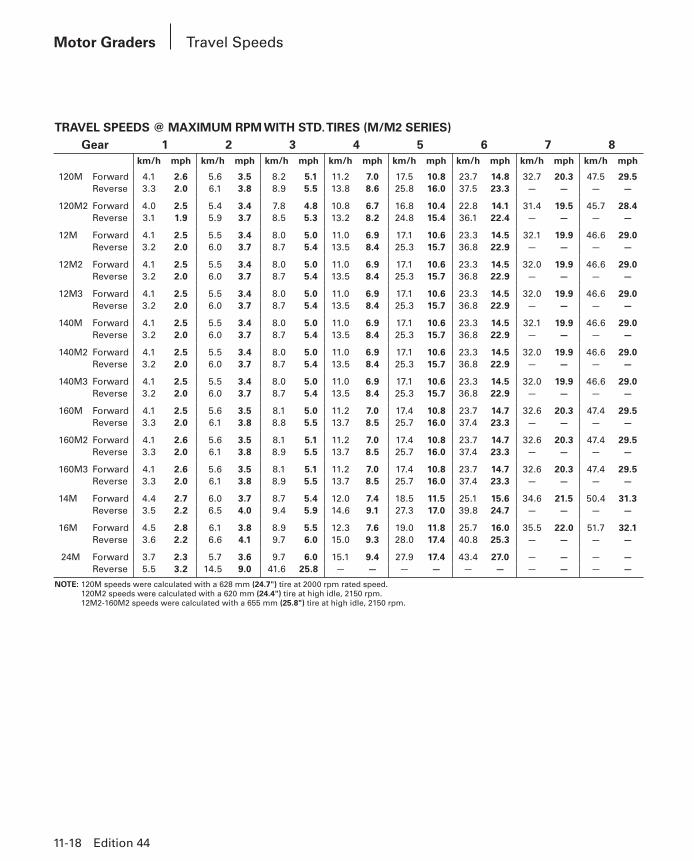
TRAVEL SPEEDS @ MAXIMUM RPM WITH STD. TIRES (M/M2 SERIES)Gear 1 2 3 4 5 6 7 8
km/h mph km/h mph km/h mph km/h mph km/h mph km/h mph km/h mph km/h mph
120M Forward 4.1 2.6 5.6 3.5 8.2 5.1 11.2 7.0 17.5 10.8 23.7 14.8 32.7 20.3 47.5 29.5Reverse 3.3 2.0 6.1 3.8 8.9 5.5 13.8 8.6 25.8 16.0 37.5 23.3 — — — —
120M2 Forward 4.0 2.5 5.4 3.4 7.8 4.8 10.8 6.7 16.8 10.4 22.8 14.1 31.4 19.5 45.7 28.4Reverse 3.1 1.9 5.9 3.7 8.5 5.3 13.2 8.2 24.8 15.4 36.1 22.4 — — — —
12M Forward 4.1 2.5 5.5 3.4 8.0 5.0 11.0 6.9 17.1 10.6 23.3 14.5 32.1 19.9 46.6 29.0Reverse 3.2 2.0 6.0 3.7 8.7 5.4 13.5 8.4 25.3 15.7 36.8 22.9 — — — —
12M2 Forward 4.1 2.5 5.5 3.4 8.0 5.0 11.0 6.9 17.1 10.6 23.3 14.5 32.0 19.9 46.6 29.0Reverse 3.2 2.0 6.0 3.7 8.7 5.4 13.5 8.4 25.3 15.7 36.8 22.9 — — — —
12M3 Forward 4.1 2.5 5.5 3.4 8.0 5.0 11.0 6.9 17.1 10.6 23.3 14.5 32.0 19.9 46.6 29.0Reverse 3.2 2.0 6.0 3.7 8.7 5.4 13.5 8.4 25.3 15.7 36.8 22.9 — — — —
140M Forward 4.1 2.5 5.5 3.4 8.0 5.0 11.0 6.9 17.1 10.6 23.3 14.5 32.1 19.9 46.6 29.0Reverse 3.2 2.0 6.0 3.7 8.7 5.4 13.5 8.4 25.3 15.7 36.8 22.9 — — — —
140M2 Forward 4.1 2.5 5.5 3.4 8.0 5.0 11.0 6.9 17.1 10.6 23.3 14.5 32.0 19.9 46.6 29.0Reverse 3.2 2.0 6.0 3.7 8.7 5.4 13.5 8.4 25.3 15.7 36.8 22.9 — — — —
140M3 Forward 4.1 2.5 5.5 3.4 8.0 5.0 11.0 6.9 17.1 10.6 23.3 14.5 32.0 19.9 46.6 29.0Reverse 3.2 2.0 6.0 3.7 8.7 5.4 13.5 8.4 25.3 15.7 36.8 22.9 — — — —
160M Forward 4.1 2.5 5.6 3.5 8.1 5.0 11.2 7.0 17.4 10.8 23.7 14.7 32.6 20.3 47.4 29.5Reverse 3.3 2.0 6.1 3.8 8.8 5.5 13.7 8.5 25.7 16.0 37.4 23.3 — — — —
160M2 Forward 4.1 2.6 5.6 3.5 8.1 5.1 11.2 7.0 17.4 10.8 23.7 14.7 32.6 20.3 47.4 29.5Reverse 3.3 2.0 6.1 3.8 8.9 5.5 13.7 8.5 25.7 16.0 37.4 23.3 — — — —
160M3 Forward 4.1 2.6 5.6 3.5 8.1 5.1 11.2 7.0 17.4 10.8 23.7 14.7 32.6 20.3 47.4 29.5Reverse 3.3 2.0 6.1 3.8 8.9 5.5 13.7 8.5 25.7 16.0 37.4 23.3 — — — —
14M Forward 4.4 2.7 6.0 3.7 8.7 5.4 12.0 7.4 18.5 11.5 25.1 15.6 34.6 21.5 50.4 31.3Reverse 3.5 2.2 6.5 4.0 9.4 5.9 14.6 9.1 27.3 17.0 39.8 24.7 — — — —
16M Forward 4.5 2.8 6.1 3.8 8.9 5.5 12.3 7.6 19.0 11.8 25.7 16.0 35.5 22.0 51.7 32.1Reverse 3.6 2.2 6.6 4.1 9.7 6.0 15.0 9.3 28.0 17.4 40.8 25.3 — — — —
24M Forward 3.7 2.3 5.7 3.6 9.7 6.0 15.1 9.4 27.9 17.4 43.4 27.0 — — — —Reverse 5.5 3.2 14.5 9.0 41.6 25.8 — — — — — — — — — —
NOTE: 120M speeds were calculated with a 628 mm (24.7") tire at 2000 rpm rated speed.120M2 speeds were calculated with a 620 mm (24.4") tire at high idle, 2150 rpm.12M2-160M2 speeds were calculated with a 655 mm (25.8") tire at high idle, 2150 rpm.
Motor Graders Travel Speeds
PHB-Sec11-14.indd 18PHB-Sec11-14.indd 18 12/20/13 8:36 AM12/20/13 8:36 AM

Edition 44 11-19
Motor Graders
11
TRAVEL SPEEDS @ MAXIMUM RPM WITH STD. TIRES (K/K2 SERIES)Gear 1 2 3 4 5 6 7 8
km/h mph km/h mph km/h mph km/h mph km/h mph km/h mph km/h mph km/h mph
120K Forward 3.9 2.4 5.3 3.3 7.7 4.8 10.7 6.6 16.8 10.4 22.8 14.2 31.4 19.5 45.7 28.4Reverse 3.1 1.9 5.8 3.6 8.4 5.2 13.3 8.2 24.8 15.4 36.1 22.4 — — — —
120K2 Forward 3.9 2.4 5.3 3.3 7.7 4.8 10.6 6.6 16.8 10.4 22.8 14.2 31.4 19.5 45.7 28.4Reverse 3.1 1.9 5.8 3.6 8.4 5.2 13.3 8.2 24.8 15.4 36.1 22.4 — — — —
12K Forward 3.8 2.4 5.2 3.2 7.6 4.7 10.4 6.5 16.5 10.2 22.4 13.9 30.8 19.2 44.8 27.9Reverse 3.0 1.9 5.7 3.5 8.2 5.1 13.0 8.1 24.3 15.1 35.4 22.0 — — — —
140K Forward 4.0 2.5 5.4 3.4 7.9 4.9 10.9 6.8 17.2 10.7 23.4 14.5 32.2 20.0 46.8 29.1Reverse 3.2 2.0 5.9 3.7 8.6 5.3 13.6 8.4 25.4 15.8 37.0 23.0 — — — —
140K2 Forward 4.0 2.5 5.4 3.4 7.9 4.9 10.9 6.8 17.2 10.7 23.4 14.5 32.2 20.0 46.8 29.1Reverse 3.2 2.0 5.9 3.7 8.6 5.3 13.6 8.4 25.4 15.8 37.0 23.0 — — — —
160K Forward 4.1 2.5 5.5 3.4 8.0 4.9 11.0 6.8 17.0 10.6 23.2 14.4 31.9 19.8 46.4 28.8Reverse 3.2 2.0 5.9 3.7 8.7 5.4 13.4 8.4 25.2 15.6 36.6 22.8 — — — —
Travel Speeds
PHB-Sec11-14.indd 19PHB-Sec11-14.indd 19 12/20/13 8:36 AM12/20/13 8:36 AM

11-20 Edition 44
Motor Graders
ALL WHEEL DRIVE (AWD) 120M2, 12M2/M3, 140M/M2/M3, 160M/M2/M3Working Range:
Forward Gears gears 1-7
Reverse Gears gears 1-5
Pump Type Variable Displacement Axial Piston Pumps (2)
Motor Type Variable Displacement Axial Piston Motors (2)
Front Wheel Gear Reduction Double Planetary Reduction
Maximum Pump Flow (each pump) 125 L/min 33 gpm
Front Wheel Torque 13 998 N·m 10,325 lb-ft
Control Type Speed control with closed-loop feedback
The optional AWD system utilizes dedicated left and right pumps for precise hydraulic control.
Gross power is automatically increased up to 26 kW (35 hp) with AWD engaged, maintaining a constant net power to the ground.
Hydrostatic Mode disengages the transmission and provides hydraulic power to the front wheels only-infinitely variable to 8 km/h (5 mph).
Exclusive AWD Steering Compensation adjusts outside front tire speed up to 50% faster than the inside tire.
Operating Pressure depends on engine speed, gear selection and operating conditions.
M10 — MID MOUNT SCARIFIER 120M/M2, 12M/M2/M3, 140M/M2/M3, 160M/M2/M3Type V-type Straight type*
Working Width 1184 mm 46.6" 1800 mm 71"
Depth (Max.) 292 mm 11.5" 317 mm 12.5"
Number of Shank Holders 11 17
Spacing 116 mm 4.6" 111 mm 4.4"
*Available on M Series Global Versions only.
FRONT MOUNT SCARIFIER 120M/M2, 12M/M2/M3, 140M/M2/M3, 160M/M2/M3Type V-type
Working Width 1205 mm 47.4"
Depth (Max.) 467 mm 18.4"
Number of Shank Holders 11
Spacing 116 mm 4.6"
All Wheel DriveMid Mount and Front Mount Scarifiers
PHB-Sec11-14.indd 20PHB-Sec11-14.indd 20 12/20/13 8:36 AM12/20/13 8:36 AM

11
Edition 44 11-21
Motor GradersRear Ripper and Rear Ripper Scarifier
MOTOR GRADER/RIPPER 120M 120M2 12M 12M2Parallelogram — Rear Mounted Ripper/
ScarifierRipper/Scarifier
Ripper/Scarifier
Ripper/Scarifier
Tire Size (Std.) 13.00 24 13.00 24 14R24 14.00R24Front and Rear 12PR (G-4) 12PR (G-2) 12PR (G-2) ★ (G-2)
ScarifierMaximum Digging Depth 267 mm 10.5" 267 mm 10.5" 267 mm 10.5" 267 mm 10.5"Number of Pockets 9 9 9 9Spacing 267 mm 10.5" 267 mm 10.5" 267 mm 10.5" 267 mm 10.5"Ripper ShankMaximum Digging Depth 428 mm 16.9" 428 mm 16.9" 428 mm 16.9" 428 mm 16.9"Maximum Reach at Ground Line 973 mm 38.3" 973 mm 38.3" 973 mm 38.3" 973 mm 38.3"Maximum Ground Clearance under
Tip (shank pinned in bottom hole) 502 mm 19.8" 502 mm 19.8" 502 mm 19.8" 502 mm 19.8"Maximum Ramp Angle, Ripper Up
(shank pinned in bottom hole) 15° 15° 15° 15°Shank Section 59 × 138 mm 59 × 138 mm 59 × 138 mm 59 × 138 mm
2.3" × 5.4" 2.3" × 5.4" 2.3" × 5.4" 2.3" × 5.4"Ripper BeamOverall Width 2.31 m 7'7" 2.31 m 7'7" 2.31 m 7'7" 2.31 m 7'7"Height 152 mm 6.0" 152 mm 6.0" 152 mm 6.0" 152 mm 6.0"Length 230 mm 9.1" 230 mm 9.1" 230 mm 9.1" 230 mm 9.1"Number of Pockets 5 5 5 5Pocket Spacing:
Inside 533 mm 1'9" 533 mm 1'9" 533 mm 1'9" 533 mm 1'9"Middle 533 mm 1'9" 533 mm 1'9" 533 mm 1'9" 533 mm 1'9"Outside 533 mm 1'9" 533 mm 1'9" 533 mm 1'9" 533 mm 1'9"
Shank Gauge 2.13 m 7'0" 2.13 m 7'0" 2.13 m 7'0" 2.13 m 7'0"Installed Weights:
Ripper with Standard Shank 1100 kg 2425 lb 1100 kg 2425 lb 1111 kg 2449 lb 1086 kg 2394 lbEach Additional Shank 31 kg 68 lb 31 kg 68 lb 31 kg 68 lb 31 kg 68 lb
Ripper Forces:Penetration Force 8454 kg 18,638 lb 9305 kg 20,514 lb 8693 kg 19,165 lb 9386 kg 20,693 lbPryout Force 10 024 kg 22,099 lb 10 516 kg 23,184 lb 10 433 kg 23,001 lb 12 141 kg 26,766 lb
PHB-Sec11-14.indd 21PHB-Sec11-14.indd 21 12/20/13 8:36 AM12/20/13 8:36 AM

11-22 Edition 44
Motor Graders Rear Ripper and Rear Ripper Scarifier
MOTOR GRADER/RIPPER 12M3 140M 140M2 140M3Parallelogram — Rear Mounted Ripper/
ScarifierRipper/Scarifier
Ripper/Scarifier
Ripper/Scarifier
Tire Size (Std.) 14.00R24 14.00-24 14.00R24 14.00R24 Front and Rear ★ (G-2) 10PR (G-2) ★ (G-2) ★ (G-2)
ScarifierMaximum Digging Depth 267 mm 10.5" 261 mm 10.3" 265 mm 10.4" 265 mm 10.4"Number of Pockets 9 9 9 9Spacing 267 mm 10.5" 267 mm 10.5" 267 mm 10.5" 267 mm 10.5"Ripper ShankMaximum Digging Depth 428 mm 16.9" 422 mm 16.6" 426 mm 16.8" 426 mm 16.8"Maximum Reach at Ground Line 973 mm 38.3" 973 mm 38.3" 973 mm 38.3" 973 mm 38.3"Maximum Ground Clearance under
Tip (shank pinned in bottom hole) 502 mm 19.8" 508 mm 20" 488 mm 19.2" 488 mm 19.2"Maximum Ramp Angle, Ripper Up
(shank pinned in bottom hole) 15° 15° 15° 15°Shank Section 59 × 138 mm 59 × 138 mm 59 × 138 mm 59 × 138 mm
2.3" × 5.4" 2.3" × 5.4" 2.3" × 5.4" 2.3" × 5.4"Ripper BeamOverall Width 2.31 m 7'7" 2.31 m 7'7" 2.31 m 7'7" 2.31 m 7'7"Height 152 mm 6.0" 152 mm 6.0" 152 mm 6.0" 152 mm 6.0"Length 230 mm 9.1" 230 mm 9.1" 230 mm 9.1" 230 mm 9.1"Number of Pockets 5 5 5 5Pocket Spacing:
Inside 533 mm 1'9" 533 mm 1'9" 533 mm 1'9" 533 mm 1'9"Middle 533 mm 1'9" 533 mm 1'9" 533 mm 1'9" 533 mm 1'9"Outside 533 mm 1'9" 533 mm 1'9" 533 mm 1'9" 533 mm 1'9"
Shank Gauge 2.13 m 7'0" 2.13 m 7'0" 2.13 m 7'0" 2.13 m 7'0"Installed Weights:
Ripper with Standard Shank 1086 kg 2394 lb 1111 kg 2449 lb 1086 kg 2394 lb 1086 kg 2394 lbEach Additional Shank 31 kg 68 lb 31 kg 68 lb 31 kg 68 lb 31 kg 68 lb
Ripper Forces:Penetration Force 9386 kg 20,693 lb 9259 kg 20,413 lb 9386 kg 20,693 lb 9386 kg 20,693 lbPryout Force 12 141 kg 26,766 lb 11 635 kg 25,651 lb 12 544 kg 27,655 lb 12 544 kg 27,655 lb
PHB-Sec11-14.indd 22PHB-Sec11-14.indd 22 12/20/13 8:36 AM12/20/13 8:36 AM

11
Edition 44 11-23
Motor GradersRear Ripper and Rear Ripper Scarifier
MOTOR GRADER/RIPPER 160M 160M2 160M3Parallelogram — Rear Mounted Ripper/
ScarifierRipper/Scarifier
Ripper/Scarifier
Tire Size (Std.) 14.00-24 14.00R24 14.00R24Front and Rear 10PR (G-2) ★ (G-2) ★ (G-2)
ScarifierMaximum Digging Depth 261 mm 10.3" 265 mm 10.4" 265 mm 10.4"Number of Pockets 9 9 9Spacing 267 mm 10.5" 267 mm 10.5" 267 mm 10.5"Ripper ShankMaximum Digging Depth 422 mm 16.6" 426 mm 16.8" 426 mm 16.8"Maximum Reach at Ground Line 973 mm 38.3" 973 mm 38.3" 973 mm 38.3"Maximum Ground Clearance under
Tip (shank pinned in bottom hole) 508 mm 20" 488 mm 19.2" 488 mm 19.2"Maximum Ramp Angle, Ripper Up
(shank pinned in bottom hole) 15° 15° 15°Shank Section 59 × 138 mm 59 × 138 mm 59 × 138 mm
2.3" × 5.4" 2.3" × 5.4" 2.3" × 5.4"Ripper BeamOverall Width 2.31 m 7'7" 2.31 m 7'7" 2.31 m 7'7"Height 152 mm 6.0" 152 mm 6.0" 152 mm 6.0"Length 230 mm 9.1" 230 mm 9.1" 230 mm 9.1"Number of Pockets 5 5 5Pocket Spacing:
Inside 533 mm 1'9" 533 mm 1'9" 533 mm 1'9"Middle 533 mm 1'9" 533 mm 1'9" 533 mm 1'9"Outside 533 mm 1'9" 533 mm 1'9" 533 mm 1'9"
Shank Gauge 2.13 m 7'0" 2.13 m 7'0" 2.13 m 7'0"Installed Weights:
Ripper with Standard Shank 1111 kg 2449 lb 1086 kg 2394 lb 1086 kg 2394 lbEach Additional Shank 31 kg 68 lb 31 kg 68 lb 31 kg 68 lb
Ripper Forces:Penetration Force 9273 kg 20,443 lb 9386 kg 20,693 lb 9386 kg 20,693 lbPryout Force 11 712 kg 25,821 lb 12 602 kg 27,783 lb 12 602 kg 27,783 lb
PHB-Sec11-14.indd 23PHB-Sec11-14.indd 23 12/20/13 8:36 AM12/20/13 8:36 AM
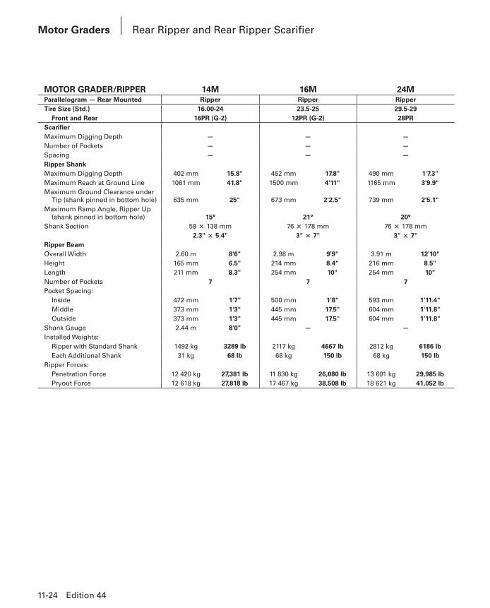
MOTOR GRADER/RIPPER 14M 16M 24MParallelogram — Rear Mounted Ripper Ripper RipperTire Size (Std.) 16.00-24 23.5-25 29.5-29
Front and Rear 16PR (G-2) 12PR (G-2) 28PRScarifierMaximum Digging Depth — — —Number of Pockets — — —Spacing — — —Ripper ShankMaximum Digging Depth 402 mm 15.8" 452 mm 17.8" 490 mm 1'7.3"Maximum Reach at Ground Line 1061 mm 41.8" 1500 mm 4'11" 1165 mm 3'9.9"Maximum Ground Clearance under
Tip (shank pinned in bottom hole) 635 mm 25" 673 mm 2'2.5" 739 mm 2'5.1"Maximum Ramp Angle, Ripper Up
(shank pinned in bottom hole) 15° 21° 20°Shank Section 59 × 138 mm 76 × 178 mm 76 × 178 mm
2.3" × 5.4" 3" × 7" 3" × 7"Ripper BeamOverall Width 2.60 m 8'6" 2.98 m 9'9" 3.91 m 12'10"Height 165 mm 6.5" 214 mm 8.4" 216 mm 8.5"Length 211 mm 8.3" 254 mm 10" 254 mm 10"Number of Pockets 7 7 7Pocket Spacing:
Inside 472 mm 1'7" 500 mm 1'8" 593 mm 1'11.4"Middle 373 mm 1'3" 445 mm 17.5" 604 mm 1'11.8"Outside 373 mm 1'3" 445 mm 17.5" 604 mm 1'11.8"
Shank Gauge 2.44 m 8'0" — —Installed Weights:
Ripper with Standard Shank 1492 kg 3289 lb 2117 kg 4667 lb 2812 kg 6186 lbEach Additional Shank 31 kg 68 lb 68 kg 150 lb 68 kg 150 lb
Ripper Forces:Penetration Force 12 420 kg 27,381 lb 11 830 kg 26,080 lb 13 601 kg 29,985 lbPryout Force 12 618 kg 27,818 lb 17 467 kg 38,508 lb 18 621 kg 41,052 lb
11-24 Edition 44
Motor Graders Rear Ripper and Rear Ripper Scarifier
PHB-Sec11-14.indd 24PHB-Sec11-14.indd 24 12/20/13 8:36 AM12/20/13 8:36 AM
11
Edition 44 11-25
Motor GradersProduction
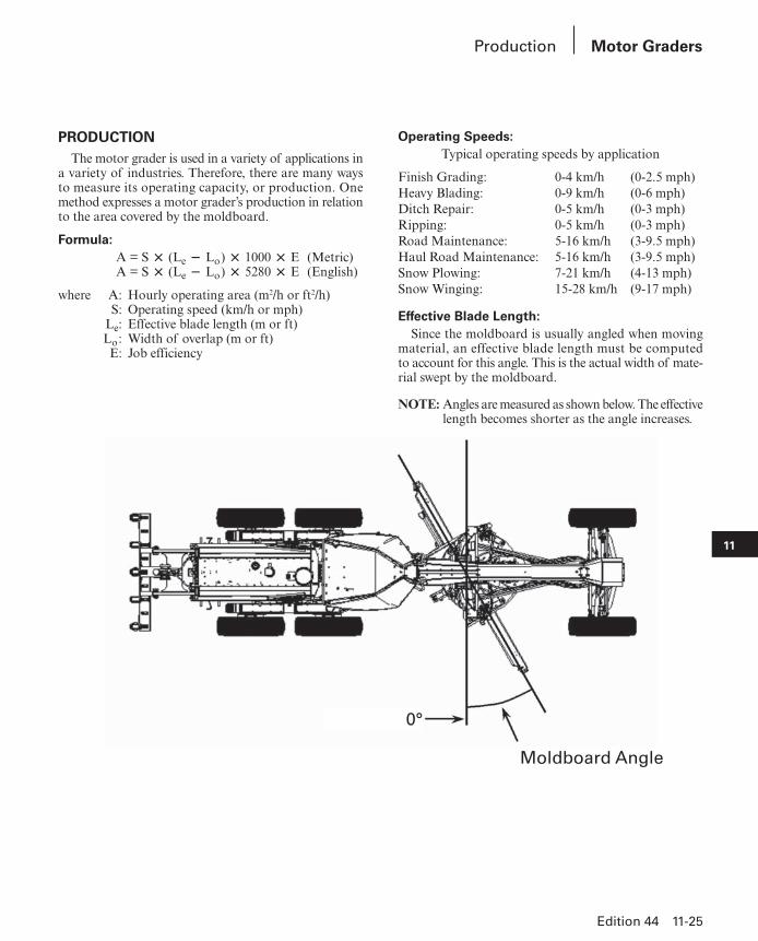
PRODUCTIONThe motor grader is used in a variety of applications in
a variety of industries. Therefore, there are many ways to measure its operating capacity, or production. One method expresses a motor grader’s production in relation to the area covered by the moldboard.
Formula: A = S × (Le − Lo) × 1000 × E (Metric)
A = S × (Le − Lo) × 5280 × E (English)
where A: Hourly operating area (m2/h or ft2/h) S: Operating speed (km/h or mph) Le: Effective blade length (m or ft) Lo: Width of overlap (m or ft) E: Job efficiency
Operating Speeds:Typical operating speeds by application
Finish Grading: 0-4 km/h (0-2.5 mph)Heavy Blading: 0-9 km/h (0-6 mph)Ditch Repair: 0-5 km/h (0-3 mph)Ripping: 0-5 km/h (0-3 mph)Road Maintenance: 5-16 km/h (3-9.5 mph)Haul Road Maintenance: 5-16 km/h (3-9.5 mph)Snow Plowing: 7-21 km/h (4-13 mph)Snow Winging: 15-28 km/h (9-17 mph)
Effective Blade Length:Since the moldboard is usually angled when moving
material, an effective blade length must be computed to account for this angle. This is the actual width of mate-rial swept by the moldboard.
NOTE: Angles are measured as shown below. The effec tive length becomes shorter as the angle increases.
Moldboard Angle
0°
PHB-Sec11-14.indd 25PHB-Sec11-14.indd 25 12/20/13 8:36 AM12/20/13 8:36 AM

11-26 Edition 44
Motor Graders Production
Moldboard Length,m (ft)
Effective Length,m (ft)
30 degree blade angle
Effective Length,m (ft)
45 degree blade angle
3.658 (12) 3.17 (10.4) 2.59 (8.5)4.267 (14) 3.70 (12.1) 3.02 (9.9)4.877 (16) 4.22 (13.9) 3.45 (11.3)7.315 (24) 6.33 (20.8) 5.17 (17.0)
For other blade lengths and carry angles: Effective length = COS [Radians (Blade L)] 3 Blade Length
Width of Overlap:The width of overlap is generally 0.6 m (2.0 ft). This
overlap accounts for the need to keep the tires out of the windrow on the return pass.
Job Efficiency:Job efficiencies vary based on job conditions, operator
skill, etc.A good estimation for efficiency is approximately
0.70 to 0.85, but actual operating conditions should be used to determine the best value.
Example problem:
A Cat motor grader with a 3.66 m (12 ft) mold board is performing road maintenance on a township road. The machine is working at an average speed of 13 km/h (8 mph) with a moldboard carry angle of 30 degrees. What is the motor grader’s production based on coverage area?
Note: Due to the long passes involved in road mainte-nance — fewer turnarounds — a higher job effi-ciency of 0.90 is chosen.
Solution:From the table, the effective blade length is 3.17 m
(10.4 ft).
MetricProduction, A = 13 km/h × (3.17 m − 0.6 m) ×
1000 × 0.90Production, A = 30 069 m2/hr (3.07 hectares/hr)
EnglishProduction, A = 8 mph × (10.4 ft − 2.0 ft) ×
5280 × 0.90Production, A = 319,334 ft2/hr (7.33 acres/hr)
To pinpoint the theoretical number of motor graders required to properly maintain your haul roads, based on your specific mining applications, please download the haul road maintenance calculator on https://catminer.cat.com.
Haul road maintenance impacts cycle time, tire, frame and drive train components, safety and ultimately your cost per ton. To achieve optimal truck productivity, your haul roads must be properly maintained.
NOTE: Moderate: ● Road Maintenance Difficult: ● Ripping● Pad Cleaning ● Spreading Dump Material● Rock Clearing ● Road Profiling/Reshaping● Shoulder Sweeping
PHB-Sec11-14.indd 26PHB-Sec11-14.indd 26 12/20/13 8:36 AM12/20/13 8:36 AM

11
Edition 44 11-27
Motor GradersFormulas
BLADE PULLThis specification is also known as drawbar pull. This
spec can be calculated as follows:Variables:Rear weight of machine = WrTire traction coefficient = T (Look up the table entitled
“Coefficient of Traction Factors”) Wr × T = Blade Pull
Example problem:
Calculate the blade pull for a 140M Global Version version machine operating in a quarry pit...Metric
RW = 10 501 kgT = 0.65
10 501 × 0.65 = 6825.65English
RW = 23,151 lbT = 0.65
23,151 × 0.65 = 15,048.15
BLADE DOWN PRESSUREThis spec can be calculated as follows:
Variables:Blade to front axle length = BAWheel base length = WBWeight on front wheels = FWBlade down pressure = BD
WB(WB – BA)
× FW = BD
Example problem:
Calculate the blade down pressure for a 140M Global Version version machine...Metric
BA = 2565 mm FW = 4223 kgWB = 6086 mm BD = ?
6086(6086 – 2565)
× 4223 = 7299 kg
English
BA = 101 in FW = 9310 lbWB = 240 in BD = ?
240(240 – 101)
× 9310 = 16,075 lb
This specification is only a minor indicator of a motor grader’s productivity. It alone gives no measure of over-all machine productivity. When considering motor grader production you need an optimum balance between the machine’s front and rear weights. If a machine has too much weight on the front axle, it might have a high blade down pressure spec. It will, however, lack the essential rear weight and traction needed to push through the load. Too much weight in the rear and it will not have the nec-es sary weight in the front during heavy cuts to maintain proper steering control.
Cat machines are built with this optimum balance in mind. A Cat Motor Grader is engineered with the proper weight distribution necessary for maximum productivity.
Effective Blade Length*Moldboard
3.66 m (12') 4.27 m (14') 4.88 m (16') 7.32 m (24')
An
gle
°
m ft m ft m ft m ft0° 3.66 12.00 4.27 14.00 4.88 16.00 7.32 24.005° 3.64 11.95 4.25 13.95 4.86 15.94 7.29 23.9110° 3.60 11.82 4.20 13.79 4.80 15.76 7.21 23.6415° 3.53 11.59 4.12 13.52 4.71 15.45 7.07 23.1820° 3.44 11.28 4.01 13.16 4.58 15.04 6.87 22.5525° 3.32 10.88 3.87 12.69 4.42 14.50 6.63 21.7530° 3.17 10.39 3.69 12.12 4.22 13.86 6.33 20.7835° 3.00 9.83 3.50 11.47 4.00 13.11 5.99 19.6640° 2.80 9.19 3.27 10.72 3.74 12.26 5.61 18.3945° 2.59 8.49 3.02 9.90 3.45 11.31 5.17 16.97
* Effective blade length is the amount of blade coverage the machine is capa-ble of when the blade is at a given angle.
PHB-Sec11-14.indd 27PHB-Sec11-14.indd 27 12/20/13 8:36 AM12/20/13 8:36 AM
11-28 Edition 44
Motor Graders Extreme Slope Operation
EXTREME SLOPE OPERATIONThere are two ways of defining slope work. The slope
perpendicular to the machine’s direction of travel is commonly referred to as “Side Sloping.” The slope par-al lel to the machine’s direction of travel — the machines ability to travel up or down terrain, is com monly referred to as “Gradeability.”
Side Sloping capability for our Cat graders is some-what subjective, but general agreement among pro fes-sional operators is that working on a slope ratio of 2.5:1 (21.8 degrees) is the safe limit … an experienced operator may be able to operate on a 2:1 (28 degrees) slope. Many factors influence this limit such as oper-ator experience, machine configuration, tires and soil conditions, but a 2.5:1 is achievable. Further, a 3:1 slope is the approximate maximum side slope a grader can work on in straight frame configuration. The steeper side slopes all require the machine be articulated to safely navigate the slope.
Gradeability is approximately 22 degrees. This is established by the grader’s ability to stop without skid-ding the tires while moving downhill. The motor grader can, however, climb grades steeper than 22 degrees. The traction coefficient is the critical factor in determining whether a grader can safely navigate the slope. Caterpillar recommends that you never climb a slope steeper than you can safely descend.
Maximum lubrication angle: We have measured the graders on a tilt table and pump cavitation occurs around 45 degrees (100% or 1:1). This is beyond the grade or slope a motor grader can operate on.
When working side hills and slopes, consideration should be given to the following important points.
● Speed of Travel — At higher speeds, inertia forces tend to make the grader less stable.
● Roughness of Terrain or Surface — Ample allowance should be made where the terrain or surface is uneven.
● Mounted Equipment — Mounted attachments such as front plows, snow wings, rippers and other mounted equipment cause the tractor to balance differently.
● Nature of Surface — New earthen fills may give way with the weight of the grader. Rocky surfaces may promote side slipping of grader.
● Excessive Loads or Side Draft — This may cause wheel slippage, where the downhill tires “dig in,” increasing the angle of grader.
● Tire Selection and Maintenance — Consid eration should be given to proper tire selection and air pres-sure. For more information, consult Caterpillar pub-lications — Motor Grader Tire Selection Guide and Opera tion and Maintenance Manual.
● Drawbar, Circle and Blade Position — The position of the blade can affect the stability of the machine.
● Articulation Angle — Articulation angle can affect the stability of the machine.
● Wheel Lean Angle — Wheel lean angle can affect the stability of the machine.
NOTE: Safe operation on steep slopes may require spe-cial machine maintenance as well as excel lent operator skill and proper equipment setup for the specific application. Consult Caterpillar pub-lications for further operating tips — Opera tion & Maintenance Manual, Motor Grader Appli ca-tion Guide, and the Grade Com pari son Chart in the Tables section of this Perfor mance Hand book.
PHB-Sec11-14.indd 28PHB-Sec11-14.indd 28 12/20/13 8:36 AM12/20/13 8:36 AM

11
Edition 44 11-29
Motor GradersWork Tools
Work Tool120M/120M2
12M/12M2/12M3
140M/140M2/140M3
160M/160M2/160M3 14M 16M 24M
Lift Group x x x x x x —
V-Plow x x x x x x —
One Way Plow x x x x x x —
Manual Reversible Plow x x x x x x —
Hydraulic Reversible Plow x x x x x x —
Snow Wing x x x x x x —
Mid Mount Scarifier x x x x — — —
Front Scarifier x x x x — — —
Manual Angle Blade x x x x x x —
Hydraulic Angle Blade x x x x x x —
Straight Blade x x x x x x —
This list is not all-inclusive.
See Price Lists, Cat Work Tools (Cat WT) Price List, and your Cat dealer for special attachment needs.
Attachments for Cat Motor Graders require additional hydraulics.
Most front-mounted attachments require a Quick Attach-Detach Parallel Lift Group.
PHB-Sec11-14.indd 29PHB-Sec11-14.indd 29 12/20/13 8:36 AM12/20/13 8:36 AM

11-30 Edition 44
Notes —
PHB-Sec11-14.indd 30PHB-Sec11-14.indd 30 12/20/13 8:36 AM12/20/13 8:36 AM