catctcessexitalyed3rev1
TRANSCRIPT
5/12/2018 CATCTCESSEXITALYed3rev1 - slidepdf.com
http://slidepdf.com/reader/full/catctcessexitalyed3rev1 1/15
ESSEX ITALY SpA
CONTINUOUSLYTRANSPOSEDCONDUCTORS
ISO 9001-2000
CERTIFICATE
CSQ 9125.PIR9
IQNET IT-897029.1.2008

5/12/2018 CATCTCESSEXITALYed3rev1 - slidepdf.com
http://slidepdf.com/reader/full/catctcessexitalyed3rev1 2/15
ESSEX ITALY SpA Cont inu ously Transpose d Conduc tor s – Ed. 3 Rev. 1 29.1.2008 2
inside .....
CONTINUOUSLY TRANSPOSED CONDUCTOR 3
PAPERLESS TRANSPOSED CONDUCTOR 4
CORDEX DIMENSIONAL PROPERTIES 5
CORDEX – TYPES OF SPECIAL ARRANGEMENTS 6
CONTROLLED PROOF STRESS COPPER STRAND RANGE 7
ENAMELLED RECTANGULAR WIRES 7
EXTERNAL SPECIAL PAPERS INSULATION 8
BONDING PROPERTIES 9
CTC DATA SHEET 10
CTC DIMENSIONAL DATA 11
MINIMUM WINDING DIAMETER AND TRANSPOSING PITCH 12
DRUMS FOR TRANSPOSED CONDUCTORS 14
ORDERING 14
This information was prepared to help users in selecting the proper material. We supply this information without representation or warranty of any kind. ESSEX ITALY SpA therefore assumes no responsibility and shall have no liability of any kind arising from the supply or use of this information. ESSEX ITALY SpA reserves the right to change this information or to stop the production of its materials without notice. Errors and omissions excepted.

5/12/2018 CATCTCESSEXITALYed3rev1 - slidepdf.com
http://slidepdf.com/reader/full/catctcessexitalyed3rev1 3/15
ESSEX ITALY SpA Cont inu ously Transpose d Conduc tor s – Ed. 3 Rev. 1 29.1.2008 3
CONTINUOUSLY TRANSPOSED CONDUCTOR
ESSEX ITALY Continuously Transposed Conductor consists of a group of
enamelled rectangular wires, generally of FORMVEX or FORMICEMENTEX type, which are
connected up parallel to the ends. In this group each strand successively and repeatedly takes on every
possible position inside the whole conductor cross-section. The strands as a whole are wrapped
generally with pure cellulose paper tapes.
This conductor is used for manufacturing low losses windings for electric machines.
The number of component strands includes all numbers between 5 and 85, though an odd number cangive a greater cross-section for the same stack size. Up to 32 paper tapes are applied as external
insulation and this permits any increase of the overall insulation between 0.8 and 6 mm.
Transposed Conductors of pure copper, special copper alloys or aluminum are available, both with
controlled proof stress bondable FORMICEMENTEX strands for short circuit resistant windings.
For dry transformers TENVEX enamelled strands insulated with polyaramid paper are generally used.
For special purposes are manufactured CTC without papers with wound monofilament.
The growth of the power of electrical machines has
increased the need of more efficiency.
Regarding the different losses in the transformer, the
use of CTC windings has improved this important
property of transformers design.
The adoption of CTC brings great advantage in
reduction of eddy current losses, particularly at the
end of the winding.
In addition it is possible to have a considerable
increase in the space factor of the winding, due to the
very small thickness of the insulation of the single
conductors and getting a more uniform distribution
of the temperature throughout the whole winding.
Using CTC, it is important to take into account the
increase in temperature of windings due to the higher
filling factor and the less uniform external paper
insulation than that obtained with coils wound with
paper-insulated rectangular conductors, thusrestraining in such manner the oil flow. The
increased power demand on the transmission and
distribution networks gave rise to an increase in the
short circuits power due to their interconnection,
particularly in countries without stable network and
low impedance constructions. The effects of short
circuits due to this fact were intensified and many
transformers broke down because of their inability
to withstand to electrodynamic stresses. In response
to these problems ESSEX ITALY developed the use
of FORMICEMENTEX CPR3 in CTC and the
special CORDEX (paperless CTC).
Epoxy bonded TransposedConductors are made covering the
enamelled rectangular wires with special epoxy
resins at B-stage (Formicementex wire).
This technique enables the user to strongly bond
together the conductors in the same standard
thermal treatment used for drying the paper
insulation of the windings.
Advantages• Transformers improve against unstable electrical
network and the risks of shorts.
• Formicementex enamelled rectangular wires used
in Transposed Conductors provide exceptionallystrong bond strength in the winding.
• Conductors in the winding become like a solid
beam and can withstand strong electrodynamic
stresses created during short circuit event.
• No special treatment is needed by the user.
FORMICEMENTEX CPR3 CTC is characterised by the following properties:
• Copper with high mechanical characteristics
(generally CPR3 with a proof stress 0.1 % of
220÷260 MPa) - in order to withstand the
electrodynamic stresses in case of short circuits.
• Rectangular wires enamelled with specialpolyvinylformol enamels resistant to transformer
oils.
• Epoxy coating over the enamelled rectangular
wires (FORMICEMENTEX) - a thin layer of
tack-free cresol-free epoxy B-stage that bond the
strands together after the thermal treatment of the
winding, getting a solid monolithic winding in
order to withstand the electrodynamic stresses in
case of short circuits.
• Wrapping the transposed conductors by special
insulation papers (thermally upgraded calendered
crepe paper) internally in contact with the strands
and externally, in order to give the best geometry
(well defined oil ducts) allowing good cooling
performance of the transformers or in some
helical coil constructions without paper
(paperless technique).
Other constructions can be made with individual
CTC Customers in order to improve particular
performances required for the winding.

5/12/2018 CATCTCESSEXITALYed3rev1 - slidepdf.com
http://slidepdf.com/reader/full/catctcessexitalyed3rev1 4/15
ESSEX ITALY SpA Cont inu ously Transpose d Conduc tor s – Ed. 3 Rev. 1 29.1.2008 4
PAPERLESS TRANSPOSED CONDUCTOR1
Our CORDEX is the best paperless CTC for transformers windings. Materials and productionmethods offer the best thermal exchange between the conductor and the oil, with the lowestpresence of foreign substances. These properties allow the maximum efficiency and durability.CORDEX CTC is a special TRANSPOSED CONDUCTOR without insulation paper but just witha transformer oil resistant polyester monofilament, wrapped around it.
The ESSEX ITALY paperless CTC has been designed with the intent to reduce transformerproduction costs.Main advantagesa) No bulging of the paperb) CTC free from oil pocket among the windingsc) Better cooling efficiencies – reduction of heat resistance between 4 and 7°C/Wd) Better space factor of the windings allowed by a reduction of the oil ducts from 5-6 mm to 2
mm.e) Smaller O.D. of the transformer with the same section in a smaller space, getting possible to
design one radial winding instead of two.f) Better working productivity due to the improving in winding time depending on the design.g) Finally more efficient transformers, smaller for the same power; from 1 to 3% of the total
transformer cost, also for less copper inside (approx. 10 ton for 600 MVA).The absence of paper, which is subject to bagging, allows a reduction of need of space for theoil channel and hence the space between turns by 25-33%. The low friction coefficientimproves the oil circulation. This allows the overall size of the winding to be reduced withconsequent saving in material cost. The absence of paper, in low voltage windings, and thereduced quantity of polyester monofilament around the bundle improves the heat dissipation,so reducing the cost for cooling the transformer (for example by allowing smaller radiators).This configuration gives the best mechanical performances and reliability together with lowtransformer oil pollution in comparison with competitors.This CTC is reducing the winding time, improving productivity. This design allows a reductionon cable length (less scrap).The CTC design is generally considered for helical winding up to 125 kVp, especially for lowvoltage windings.The Transposed Conductor is wound with one or more oil-resistant plastic monofilaments(generally 2 or 3 wires close together in two directions).Papers can be set on one side in order to allow the direct contact of the CTCs of sequentialwinding turns.A protection paper is given in order to avoid contamination and it is easily removed just before the winding point, pulling a plastic wire inserted along the Transposed Conductor.An adhesive tape keeps together the pieces of the cut sacrifice paper.
1 Patent IT01290307 WO9836431 EP859381
5/12/2018 CATCTCESSEXITALYed3rev1 - slidepdf.com
http://slidepdf.com/reader/full/catctcessexitalyed3rev1 5/15
ESSEX ITALY SpA Cont inu ously Transpose d Conduc tor s – Ed. 3 Rev. 1 29.1.2008 5
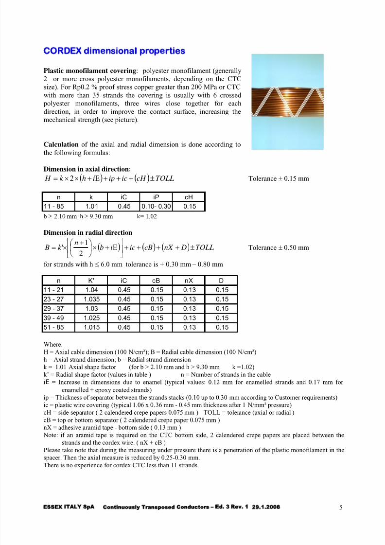
CORDEX dimensional properties
Plastic monofilament covering: polyester monofilament (generally
2 or more cross polyester monofilaments, depending on the CTC
size). For Rp0.2 % proof stress copper greater than 200 MPa or CTC
with more than 35 strands the covering is usually with 6 crossedpolyester monofilaments, three wires close together for each
direction, in order to improve the contact surface, increasing the
mechanical strength (see picture).
Calculation of the axial and radial dimension is done according to
the following formulas:
Dimension in axial direction:
( ) ( ) TOLLcH icipihk H ±+++Ε+××= 2 Tolerance ± 0.15 mm
n k iC iP cH
11 - 85 1.01 0.45 0.10- 0.30 0.15
b ≥ 2.10 mm h ≥ 9.30 mm k= 1.02
Dimension in radial direction
( ) ( ) ( ) TOLL DnX cBicibn
k B ±++++⎥⎦
⎤⎢⎣
⎡Ε+×⎟
⎠
⎞⎜⎝
⎛ +×=
2
1' Tolerance ± 0.50 mm
for strands with h ≤ 6.0 mm tolerance is + 0.30 mm – 0.80 mm
n K' iC cB nX D
11 - 21 1.04 0.45 0.15 0.13 0.15
23 - 27 1.035 0.45 0.15 0.13 0.15
29 - 37 1.03 0.45 0.15 0.13 0.15
39 - 49 1.025 0.45 0.15 0.13 0.15
51 - 85 1.015 0.45 0.15 0.13 0.15
Where:
H = Axial cable dimension (100 N/cm²); B = Radial cable dimension (100 N/cm²)
h = Axial strand dimension; b = Radial strand dimension
k = 1.01 Axial shape factor (for b > 2.10 mm and h > 9.30 mm k =1.02)
k’ = Radial shape factor (values in table ) n = Number of strands in the cable
iE = Increase in dimensions due to enamel (typical values: 0.12 mm for enamelled strands and 0.17 mm forenamelled + epoxy coated strands)
ip = Thickness of separator between the strands stacks (0.10 up to 0.30 mm according to Customer requirements)
ic = plastic wire covering (typical 1.06 x 0.36 mm - 0.45 mm thickness after 1 N/mm² pressure)
cH = side separator ( 2 calendered crepe papers 0.075 mm ) TOLL = tolerance (axial or radial )
cB = top or bottom separator ( 2 calendered crepe paper 0.075 mm )
nX = adhesive aramid tape - bottom side ( 0.13 mm )
Note: if an aramid tape is required on the CTC bottom side, 2 calendered crepe papers are placed between the
strands and the cordex wire. ( nX + cB )
Please take note that during the measuring under pressure there is a penetration of the plastic monofilament in the
spacer. Then the axial measure is reduced by 0.25-0.30 mm.
There is no experience for cordex CTC less than 11 strands.

5/12/2018 CATCTCESSEXITALYed3rev1 - slidepdf.com
http://slidepdf.com/reader/full/catctcessexitalyed3rev1 6/15
ESSEX ITALY SpA Cont inu ously Transpose d Conduc tor s – Ed. 3 Rev. 1 29.1.2008 6
CORDEX – types of special arrangements
Cordex is available with the following arrangements:
ARRANGEMENT APPLICATION PROPERTIES PIC.
CORDEX only with
protection paper
LV winding See page 4
CORDEX1 with 2 layerspapers at the bottom in radial
dimension
LV winding when its betterto split CTC in two due to
the big radial dimension
With the same single widthof the strand it is possible to
reach very high radial
dimension
1
CORDEX2 with 2 layers
papers in axial dimension
Layer winding It is possible to increase the
cooling, reducing spaces
2
CORDEX3, same as
CORDEX1 plus aramid
paper at the bottom in radial
dimension for easy winding(only for width greater than 11
mm - this paper has a cold stick
acrylic adhesive)
LV and HV disk winding Increasing cooling reducing
spaces in LV and HV
3
For the right use of these products please contact our Technical dept.
Picture 1
Picture 2
Picture 3

5/12/2018 CATCTCESSEXITALYed3rev1 - slidepdf.com
http://slidepdf.com/reader/full/catctcessexitalyed3rev1 7/15
ESSEX ITALY SpA Cont inu ously Transpose d Conduc tor s – Ed. 3 Rev. 1 29.1.2008 7
CONTROLLED PROOF STRESS COPPER STRAND RANGEThe single strand is generally E-Cu58 copper but can be also produced in aluminium and silver bearing copper.
When cold worked, the required minimum yield strength will be on the order document with a tolerance of
Minimum yield
strength range
Tolerance
MPa60-(130) + 30
130-160 + 50
> 160 + 30 MPa or + 20% which ever is higher
or it can be produced according to EN 13601:2002 (CPR Rp0.1% designation) or to other designation (Rp0.2%):
In bold compulsory values
Maximum Rp0.2% is 280 MPa.
1
2
3
4
2 4 6 8 10
b (mm)
h (mm)
12
transposable strand range
preferred range for 33 to 85 strands
h/b <
2.5
h/b >
Controlled
proof stress
copper
EN 13601
designation
Rp(0.2%)
Typical
MPa
annealed R200 60-100
CPR05 R200 90-120 CPR05/1 ------ 120-150
CPR1 R230 150-210
CPR2 R250 180-230
CPR3 R280 230-280
CuAg 0.1 Check
availability
ENAMELLED RECTANGULAR WIRES
DESIGNATION TYPE OF ENAMEL GRADE INCREASE IN
DIMENSIONS
(mm)
FORMVEX Polyvinylformol resins 1
2
0.09 ± 0.02
0.12 ± 0.03
TENVEX 200 Polyesterimide+polyamideimide resins 1
2
0.09 ± 0.02
0.15 ± 0.03
FORMICEMENTEX polyvinylformol + B-stage epoxy resins 1
2
0.13 ± 0.03
0.17 ± 0.03
IEC 60317-0-2 increase in dimensions are considered under Customer request.B-stage epoxy coating 0.03-0.05 mm allows good adhesion of the strands for treatment at (120±10)°C 24 h for
storage at temperature not greater then 32°C up to 8 months (or up to 6 months for treatment at (110±10)°C 48 h).
Good bonding is achieved in Lab specimens after treatment at (130±10)°C for 16 hours or (120±10)°C for 24 hours
or (110±10)°C for 48 hours. Industrial treatment conditions should be defined after practical tests.
Grade1 is considered if not otherwise specified in the order.
IEC 60851 test methods, IEC60317-0-2 General Requirements, IEC 60317-18 (Formvex and Formicementex), IEC
60317-28 (Tenvex H) and IEC 60317-29 (Tenvex 200), if not otherwise specified in the order.

5/12/2018 CATCTCESSEXITALYed3rev1 - slidepdf.com
http://slidepdf.com/reader/full/catctcessexitalyed3rev1 8/15
ESSEX ITALY SpA Cont inu ously Transpose d Conduc tor s – Ed. 3 Rev. 1 29.1.2008 8
EXTERNAL SPECIAL PAPERS INSULATION
TYPE OF PAPER RECOMM.THICKNESS
(µm)
APPLICATIONS MAIN PROPERTIES
Kraft 65 - 80 general purposes high purity 5A2-1M3
High density 110 general purposes high Tgδ, high density and dielectric strength
High densitythermally upgraded
crepe
75 inner and outermostlayers (*)
high mechanical and thermal properties
Thermallyupgraded paper
65 - 80 - 105 -130
inner and outermostlayers (*)
high thermal properties
Epoxy coated kraft 75 inner and outermostlayers
bonding purposes and reducing bagging effect
Aramid paper 50 thermal class 200 high temperature resistant
PET film 50 Gas transformers
Glass fabric tape 120 external protection
Monofilament 450 paper-less application No bulging of the paper; CTC free from oilpocket among the windings; better coolingefficiencies; better space factor of the windings;smaller transformer O.D.
(*) also for general purposes
All papers for electrical applications according to IEC 60554. Other types of papers are available on request
Papers arrangement Unless otherwise agreed with Customer, the insulation shall consist of at least three layers of 80 µm kraft paper.
The paper covering shall be applied according to the following arrangement or according to Customer request:
• Papers are wound
• up to 8 papers, in the same direction
• above 8 papers, in opposite direction, in groups of maximum 8 papers.
• The inner layers papers shall be butt lapped and staggered from 25 to 40 %. The two outmost layers shall be
wound interlocked by 50%.
Agreement with the Customer will be required in case of change of thickness of one or more papers or the type of
arrangement, in order to reach the required paper insulation thickness.
5/12/2018 CATCTCESSEXITALYed3rev1 - slidepdf.com
http://slidepdf.com/reader/full/catctcessexitalyed3rev1 9/15
ESSEX ITALY SpA Cont inu ously Transpose d Conduc tor s – Ed. 3 Rev. 1 29.1.2008 9
BONDING PROPERTIES
Epoxy bonded Transposed Conduct ors are made covering the enamelled rectangular wires
with special epoxy resins at B-stage (Formicementex wire).
This technique enables the user to strongly bond together the conductors in the same standard thermal
treatment used for drying the paper insulation of the windings.
FORMICEMENTEX® Charac ter i s t i csEpoxy is a thermosetting resin.
Enamelled wires are covered with a thin layer of epoxy tack-free cresol-free resin at B-stage.
ESSEX ITALY epoxy system is characterised by the following properties.
• Uniform melting
• High grade curing
• Stability of B-stage (more than 6 months at 32°C)
• Strands bonding during the drying process of the winding
• Available for medium (100-110 °C) and high (110-120 °C) operative temperature
Advantages
• Transformers improve against unstable electrical network and the risks of shorts.
• Formicementex enamelled rectangular wires used in Transposed Conductors provide exceptionally
strong bond strength in the winding.
• Conductors in the winding become like a solid beam and can withstand strong electrodynamic stresses
created during short circuits event.
• Epoxy resin cure in the same thermal treatment for drying paper (100-130°C)
• The best oil resistance
• Each single strand has better insulation
• Tack-free surface and then dust-free and easy handling of the strip without powder residues• No-pollution because the B-stage resin does not contain residues of harmful solvents
• Small thickness of coating needed in order to achieve very strong bonding (0.02-0.05 mm)
• Better sliding among the strands, improving the CTC windability
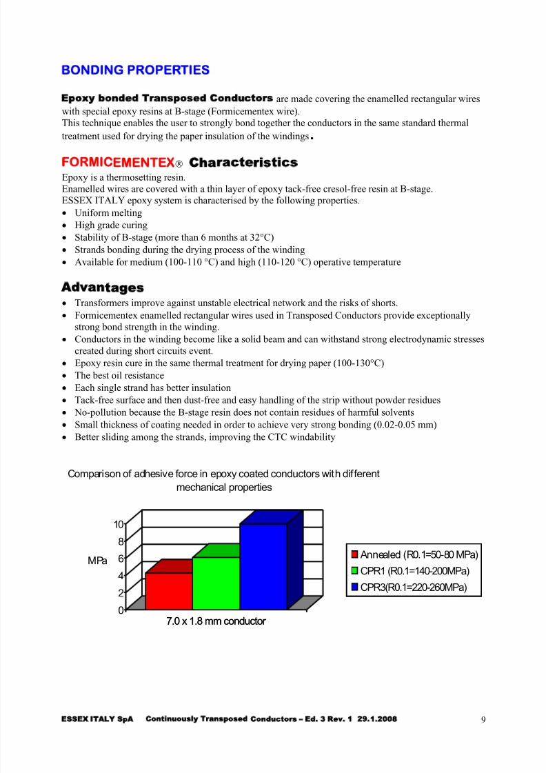
7.0 x 1.8 mm conductor0
2
4
6
8
10
MPa
7.0 x 1.8 mm conductor
Comparison of adhesive force in epoxy coated conductors with different
mechanical properties
Annealed (R0.1=50-80 MPa)
CPR1 (R0.1=140-200MPa)
CPR3(R0.1=220-260MPa)

5/12/2018 CATCTCESSEXITALYed3rev1 - slidepdf.com
http://slidepdf.com/reader/full/catctcessexitalyed3rev1 10/15
ESSEX ITALY SpA Cont inu ously Transpose d Conduc tor s – Ed. 3 Rev. 1 29.1.2008 10
CTC DATA SHEET
Enamelled rectangular wire Transposed ConductorNumber of strands From 5 to 81 Separator thickness 0.10 0.20 0.30
Max. width 12.5 Max. radial dimension 802
Min. width 2.8 Min. radial dimension 4
Max. Thickness 3.75 Max. axial dimension 25Min. Thickness 1.12 3 Min. axial dimension 5
Preferred ratio h/b 2.0-6.5 Preferred ratio
B/H =( ) ( )
( )
n b i
h i
+ × +
× +
1
4
Ε
Ε
Radial /Axial ratio less or equal
to 7
All dimensions are in mm
2 dimension without insulation paper3 depending on the preferred ratio value
5/12/2018 CATCTCESSEXITALYed3rev1 - slidepdf.com
http://slidepdf.com/reader/full/catctcessexitalyed3rev1 11/15
ESSEX ITALY SpA Cont inu ously Transpose d Conduc tor s – Ed. 3 Rev. 1 29.1.2008 11
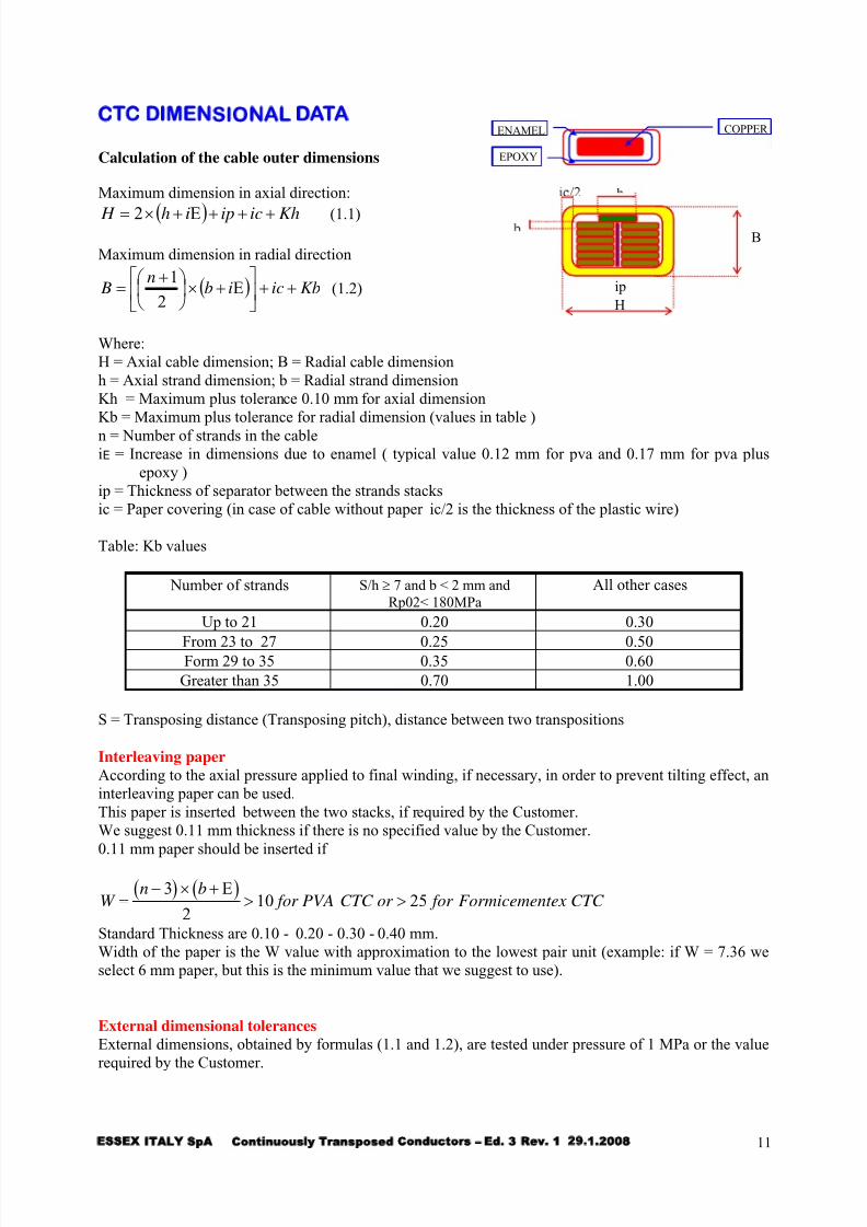
CTC DIMENSIONAL DATA
B
H
ip
EPOXY
ENAMEL COPPER
Calculation of the cable outer dimensions
Maximum dimension in axial direction:
( ) Khicipih H +++Ε+×= 2 (1.1)
Maximum dimension in radial direction
( ) Kbicibn
B ++⎥⎦
⎤⎢⎣
⎡Ε+×⎟
⎠
⎞⎜⎝
⎛ +=
2
1(1.2)
Where:
H = Axial cable dimension; B = Radial cable dimension
h = Axial strand dimension; b = Radial strand dimension
Kh = Maximum plus tolerance 0.10 mm for axial dimension
Kb = Maximum plus tolerance for radial dimension (values in table )
n = Number of strands in the cable
iE = Increase in dimensions due to enamel ( typical value 0.12 mm for pva and 0.17 mm for pva plus
epoxy )
ip = Thickness of separator between the strands stacks
ic = Paper covering (in case of cable without paper ic/2 is the thickness of the plastic wire)
Table: Kb values
Number of strands S/h ≥ 7 and b < 2 mm and
Rp02< 180MPa All other cases
Up to 21 0.20 0.30
From 23 to 27 0.25 0.50Form 29 to 35 0.35 0.60
Greater than 35 0.70 1.00
S = Transposing distance (Transposing pitch), distance between two transpositions
Interleaving paper
According to the axial pressure applied to final winding, if necessary, in order to prevent tilting effect, an
interleaving paper can be used.
This paper is inserted between the two stacks, if required by the Customer.
We suggest 0.11 mm thickness if there is no specified value by the Customer.
0.11 mm paper should be inserted if
( ) ( )W
n b for PVA CTC or for Formicementex CTC =
− × +> >
3
210 25
Ε
Standard Thickness are 0.10 - 0.20 - 0.30 - 0.40 mm.
Width of the paper is the W value with approximation to the lowest pair unit (example: if W = 7.36 we
select 6 mm paper, but this is the minimum value that we suggest to use).
External dimensional tolerances
External dimensions, obtained by formulas (1.1 and 1.2), are tested under pressure of 1 MPa or the value
required by the Customer.

5/12/2018 CATCTCESSEXITALYed3rev1 - slidepdf.com
http://slidepdf.com/reader/full/catctcessexitalyed3rev1 12/15
ESSEX ITALY SpA Cont inu ously Transpose d Conduc tor s – Ed. 3 Rev. 1 29.1.2008 12
MINIMUM WINDING DIAMETER AND TRANSPOSING PITCHThe first property to satisfy is the windability of CTC on the transformer core.
Generally the length in which there is a complete transposition of one strand (called stranding pitch)
should be less than the circumference of the core.
This requirement is due to the flexibility of the CTC in order to avoid any damage of the CTC structure.
We define 3 elements: transposition pitch, transposition length, stranding pitch.Minimum winding diameter is in relationship with the dimensional characteristics and the stranding
pitch by the following formula:
π × = × Di S n stranding pitch
S M h= × transposing pitch
Where:
S = Transposing distance (Transposing pitch), distance between two transpositions
M = S/h = Proportionality coefficient - transposing
factor (if less than 5, Kb shall be agreed during the
contract review).
lt S< ×05.
If M is lower than 5 it can be difficult to produce
the CTC for strand width greater than 6 mm,
because the pitch can be too small for the transposingmachine. If n is large, the pitch must be short but not
too short to get M lower than 5.
Transposition length - lt lt is the measured length on the CTC between two points where the strand goes from one side to the
other side of the CTC stack. The transposition length should be less than 50 % of the transposition pitch
to increase the slip among the strands in the transposition area and in order to reduce the value of the
radial coefficient Kb.
5/12/2018 CATCTCESSEXITALYed3rev1 - slidepdf.com
http://slidepdf.com/reader/full/catctcessexitalyed3rev1 13/15
ESSEX ITALY SpA Cont inu ously Transpose d Conduc tor s – Ed. 3 Rev. 1 29.1.2008 13
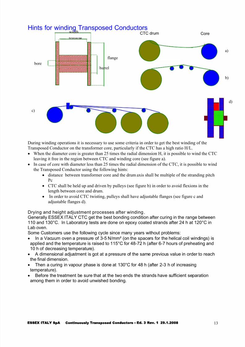
Hints for winding Transposed Conductors
barrel
flange
v
width CTC drum Core
a)
bore
b)
d)
c)
During winding operations it is necessary to use some criteria in order to get the best winding of the
Transposed Conductor on the transformer core, particularly if the CTC has a high ratio H/L.
• When the diameter core is greater than 25 times the radial dimension H, it is possible to wind the CTC
leaving it free in the region between CTC and winding core (see figure a).
• In case of core with diameter less than 25 times the radial dimension of the CTC, it is possible to wind
the Transposed Conductor using the following hints:
• distance between transformer core and the drum axis shall be multiple of the stranding pitch
Pc• CTC shall be held up and driven by pulleys (see figure b) in order to avoid flexions in the
length between core and drum.
• In order to avoid CTC twisting, pulleys shall have adjustable flanges (see figure c and
adjustable flanges d).
Drying and height adjustment processes after winding.Generally ESSEX ITALY CTC get the best bonding condition after curing in the range between110 and 130°C. In Laboratory tests are done on epoxy coated strands after 24 h at 120°C inLab oven.Some Customers use the following cycle since many years without problems:
• In a Vacuum oven a pressure of 3-5 N/mm² (on the spacers for the helical coil windings) is
applied and the temperature is raised to 115°C for 48-72 h (after 6-7 hours of preheating and10 h of decreasing temperature).
• A dimensional adjustment is got at a pressure of the same previous value in order to reachthe final dimension.
• Then a curing in vapour phase is done at 130°C for 48 h (after 2-3 h of increasingtemperature).
• Before the treatment be sure that at the two ends the strands have sufficient separationamong them in order to avoid unwished bonding.

5/12/2018 CATCTCESSEXITALYed3rev1 - slidepdf.com
http://slidepdf.com/reader/full/catctcessexitalyed3rev1 14/15
ESSEX ITALY SpA Cont inu ously Transpose d Conduc tor s – Ed. 3 Rev. 1 29.1.2008 14
DRUMS FOR TRANSPOSED CONDUCTORS
Standard wooden drums (B – returnable type and P- not returnable drums).
Type Max.
content
Dimensions (mm)
kg flange barrel bore width traverse
B100/400 700 1350 1000 82 400 290B100/610 1100 1350 1000 82 610 486
B130/810 2100 1650 1290 82 810 686
B140/1010 4000 2000 1400 82 1010 860
B160/1010 3000 2000 1600 82 1010 860
P100/S 1100 1200 800 82 610 490
P100/L 1600 1200 800 82 710 590
P160/S 2000 1600 900 82 610 450
P160/L 2800 1600 900 82 710 550
All dimensions are in mm.
Drums type B100-B130-B140-B160 may be fitted with separators to permit parallel winding of 2 or
more cables. Other types of not returnable drums are available upon request.
ORDERINGWhen ordering ESSEX ITALY Continuously Transposed Conductors, the following requirements are
necessary:
• number of strands and their nominal dimensions
• type of copper and type of enamelling wires (epoxy or not)
• minimum winding diameter• total paper thickness, minimum number of layers and type of papers
• interleaving paper and its thickness
• required length and type of drum
Please use our card for Contract Review (see next page) or ask our Sales Dept. for the use of internet
BtoB in www.invexonline.it.
5/12/2018 CATCTCESSEXITALYed3rev1 - slidepdf.com
http://slidepdf.com/reader/full/catctcessexitalyed3rev1 15/15
ESSEX ITALY SpA Cont inu ously Transpose d Conduc tor s – Ed. 3 Rev. 1 29.1.2008 15
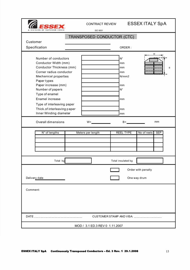
CONTRACT REVIEW ESSEX ITALY SpA
ISO 9001
TRANSPOSED CONDUCTOR (CTC)
Customer
Specification ORDER :
W
Number of conductors N°
Conductor Width (mm) mm
Conductor Thickness (mm) mm B
Corner radius conductor mm
Mechanical properties N/mm2
Paper types
Paper increase (mm) mm
Number of papers N°
Type of enamelEnamel increase mm
Type of interleaving paper
Thick.of interleaving paper mm
Inner Winding diameter mm
Overall dimensions W= B= mm
N°of lengths Meters per length REEL TYPE No of reels SEP
Total kg Total insulated kg
Order with penalty
Delivery date One way drum
Comment:
DATE _______________________________ CUSTOMER STAMP AND VISA: __________________
MOD / 3.1 ED.3 REV 0 1.11.2007