catalogue safe product solutions for photovoltaic plants ... · pdf filesafe product solutions...
TRANSCRIPT

PASSION FOR POWER.
CATALOGUESafe product solutions for Photovoltaic plants
2016/2017

The photovoltaic market is going to grow significantly in coming years as more and more inve-
stors and home owners are betting on solar power‘s high margin electricity. With our ENYSUN
distribution board systems for photovoltaic plants conforming to standards, we support you in
accessing this market. ENYSUN is a high value, modular system, which generates additional
sales potential for you on the growing photovoltaic market.
Profit from a system which offers you clear competitive advantages on the market and which
you can always rely on.
Solar powered by Hensel
Professional Photovoltaic Distributors
Hensel is the market leader in innovative products and services for
electrotechnical building facility.
Where environmental influences, dust and
moisture demand particularly demanding
installation technology, Hensel enables
safe energy distribution with innovative
solutions. The program of modern instal-
lation and distribution systems for national
and international applications have made
HENSEL a market leader in tapping, fusing
and distributing electrical energy in the low
voltage sector.
Hensel guarantees its customers continu-
ally high standard of quality with decades of
production expertise and a quality manage-
ment system strictly in adherence with the
DIN EN ISO 9001-2008 standard at all its
factories.
Founded in 1931, Hensel is now part of
an international group of companies do-
ing business around the world. It has its
headquarters in Lennestadt, Germany and
subsidiaries in the most important interna-
tional markets to provide an international
presence and assure that the company is
never far away.
Successfully mastering the future means
cooperation in dialog for Hensel. The
exchange with market partners and the
consistent focus on practical challenges is
a transfer that provides valuable inspiration
for further development of products and
services.

| 3
Safe Product Solutions for Photovoltaics
Safe Product Solutions for Photovoltaics 4
Standard Requirements for the Installation of Photovoltaic Plants 5
System description 6
PV generator junction boxes 7 - 27
Solar Inverter Collectors 28 - 41
Disconnetion switch 42 - 43
Accessories for Product Solutions for Photovoltaics, Typ Mi PV 44 - 58
Technical Data 59 - 68
Further technical information can be found on the Internet
www.hensel-electric.de/en -> Products

4 | www.hensel-electric.de/en
ENYSUN Safe Product Solutions for Photovoltaics
2
2
3
4
5
1
Solar panels
Inverters
PV generator junction boxes
Distributor with metering
Solar inverter collectors
2
1
3
4
5

| 5
Solar inverters712.434.1
The PV supply cable on the AC side shall be protected by a short circuit or an overcurrent protective
device installed at the connection to the AC mains.
712.536.2.2.1
In the selection and erection of devices for isolation and switching to be installed between the PV installa-
tion and the public supply, the public supply shall be considered the source and the
PV installation shall be considered the load.
ENYSUN Standard Requirements
for the Installation of Photovoltaic Plants
In the setting up of photovoltaic power supply systems a multitude of
standards and regulations are to be observed.
The following standard requirements are listed in extract.
IEC 60364-7-712
Electrical installations of buildings –
Part 7-712: requirements for special installations or locations –
Solar photovoltaic (PV) power supply systems
PV module712.511.1
PV modules shall comply with the requirements of the relevant equipment standard, e.g. IEC 61215 for
crystalline PV modules. PV modules of class II construction or with equivalent insulation are recommend-
ed if UOC STC1) of the PV strings exceeds 120 V d.c..
Generator junction boxes712.413.2
Protection by use of class II or equivalent insulation should preferably be adopted on the DC side.
712.536.2.2.5.1
All junction boxes (PV generator and PV array boxes) shall carry a warning label indicating that active
parts inside the boxes may still be live after isolation from the PV inverter.
712.512.1.1
Electrical equipment on the DC side shall be suitable for direct voltage and
direct current.
IEC 61439-1
Low-voltage switchgear and controlgear assemblies -
Part 1: General rules
10.9.4 Testing of enclosures made of insulating material
For assemblies with enclosures made of insulating material, an additional dielectric test shall be carried
out,…
For this additional test, the test voltage shall be equal to 1.5 times the values indicated in Table 8.
Grid
230/400 V a.c.
SPD
SPD
>I >I >I >I

6 | www.hensel-electric.de/en
Electrical parameters
Electrical parameters
Rated current: up to 630 A
Rated insulation voltage: 690 V a.c., 1000 V d.c., IEC 60664
The rated insulation voltage is possibly reduced by the installed equipment technology.
Ambient conditions
Ambient temperature
- for distribution boards according to IEC 61439:
-5 °C up to 35 °C, max. + 40 °C
Relative humidity: 50% at 40 °C, 100% at 25 °C
Application area
The enclosures are suitable for protected
outdoor installation
However the climatic infl uences and effects on
the equipment are to be considered, see pages
“outdoor applications”.
Insulation
Insulated enclosures
(Protection class II) �
IK08(5Joule)
Impact strength
degree of protection against
mechanical load IK 08
(5 Joule) in accordance with
IEC 62262
IP65
Protection against foreign solid objects and direct contact
Dust-proof
Degree of protection IP 65
IP65
Protection against ingress of water with harmful effects
Protected against water jets
Degree of protection IP 65
Dependent on the system
960°C
Burning behaviour
Glow wire test 960 °C
in accordance with IEC 60695-2-11
fl ame-retardant, self-extinguishing
UV resistance
UV resistance according to
IEC 61439-1, Section 10.2.4:
the material is examined for UV
resistance
Chemical resistance
Resistance against acid
10% and lye 10%, petrol
and mineral oil
Toxic behavour
Silicone- and halogen-free
Material: Polycarbonat
Dependent on material
System properties

| 7
PV generator junction boxes
Connection:
Ready for connection
with plug-in connectors
Electrical data:
Rated voltage: 1000 V d.c.
Rated current: up to 400 A
Protective measure: Total insulation � Ambient conditions:
UV resistant
Degree of protection: IP 65
Stainless steel external brackets
optional: suitable products to effec-
tively reduce the accumulation of
condensation in enclosures
(e.g. pressure compensation
elements, canopy, ventilation flanges)
ENYSUN
���
�� �� �� ��
��
��
���
Solar inverter
Solar inverter
collector
Distribution board
Solar modules
PV Generator
junction box
Grid 230/400V a.c.

8 | www.hensel-electric.de/en
ENYSUN Outdoor Application
DC
AC
Ambient conditions:
Degree of protection: IP 65
Stainless steel external brackets,
optional: suitable products to effectively reduce the
accumulation of condensation in enclosures (e.g. pressure
compensation elements, canopy, ventilation fl anges).
The materials used in Mi System enclosures are generally UV resistant meaning that the mechanical stabi-
lity shall remain after UV exposure.
Direct solar radiation as well as power dissipation within a box can overheat the interior of the box. Exterior
temperatures that are too low e.g. under -5°C can also infl uence the functioning of the equipment. There-
fore climatic infl uence on the equipment needs to be taken into consideration.
The top of the box should be protected with a cover to protect against impact created by weather condi-
tions such as rain, ice and snow.
Possible impact from chemical infl uences also needs to be taken into consideration when selecting an
installation location, as well as IP degree of protection and climate impact.
Additional measures might be necessary such as ventilation (note degree of protection) to assure that the
maximum ambient temperature allowed is not exceeded for the installed equipment as well as to prevent
condensation from forming. In outdoor installations Hensel combi climate glands (KBM) can be used for
cable entry and pressure compensation as well (see accessories).
Product solutions
see accessories
outdoor
application
Condensed water only forms in enclosures with a higher degree of protection than IP
54 due to temperature difference from inside to outside. Humidity can not evaporate
because of the high degree of protection of the enclosure.
How does condensed water
occur in enclosures with a
high degree of protection?
Here condensed water can be formed
dependent on the weather, high air hu-
midity, direct sunlight and temperature
differences compared to the wall.
In areas where high levels of air humi-
dity and large temperature fl uctuations
are expected e.g. in laundry rooms,
kitchens, car washes etc.
Formation of condensed water in protected
outdoor installations (protected against weather
infl uences) or unprotected outdoor installations:
Formation of condensed water for
indoor installations:
System switched on.
System switched on.
The internal temperature is higher than the external
temperature due to the power dissipation of the built-in
devices.
The warm air inside the enclosure attempts to accumulate
moisture. This comes from outside through the seal as the
enclosures are not gas-tight.
The internal temperature is reduced by cooling down the
system e.g. by switching off the loads. The cooler air emits
moisture which is collected as condensed water on the
cooling inner surfaces.
System switched off.

| 9
ENYSUN Overvoltage Protection
Through the exposed assembly of photovoltaic generators on rooftops or in the free surface the lightning
and surge protection is an important part of investment protection.
Direct lightning strikes in the PV generator can for example destroy PV modules and inverters (primary
damage).
Since photovoltaic (PV) systems necessarily have a connection to the electrical installation of the building,
damages throughout the whole plant can result from lightning strikes in the PV generator (secondary
effect).
Protection measures
Basically, it should be ensured that no direct lightning strike to the PV generator is possible. Well-known
manufacturers offer suitable products for ”external lightning protection systems.“
Is an external lightning protection system installed, a lightning current arrester type 1 for the AC supply is
required in the building main distribution board.
Protection of solar inverters
To protect the inverters against surge voltages, both the DC inputs and AC outputs must be protected.
When the inverter is installed at a distance of more than 10 m cable length to the buildings main power
distribution, then a surge protection device (SPD) type 2 for the AC line shall be used to prevent overvol-
tage damage, such as switching overvoltage from the electrical power supply.
For the string lines of the DC inputs special type 2 surge protection devices are to be provided, which are
suitable for direct voltage. The decisive factor is the individual lightning and surge protection concept.The experts answer
all questions for
lightning and
surge protection!
DC
AC
Typ 2 Typ 1
l > 10 m? l > 10 m?
Typ 2 Typ 1
Typ 1 Typ 1
Typ 2
l > 10 m?
Typ 2
Typ 1
>I >I >I >I
External light-
ning protection
is available?
Separation
distance* s
is maintained?Mounting frame
connected with
external lightning
protection!
yes
yes
yes
yesyes
no
no
no no no
Solar modules
PV Generator
junction box
incl.
Solar inverter
Solar inverter
collector incl.
Distribution
boardGrid 230/400V a.c.
SPD
SPD
AC SPD
Type 1
AC SPD
Type 1
AC SPD
Type 1
AC SPD
Type 1
AC SPD
Type 2
AC SPD
Type 2
DC SPD
Type 2
DC SPD
Type 2
DC SPD
Type 1
* between lightning protection facility and PV plant

10 | www.hensel-electric.de/en
PV panel technology
Blocking diodeDC generator
disconnect switchString overload
protection
How to choose the correct overload protection for PV generator
Which
PV panel
technology is
used?
YES
Is
string
overload
protection
required?
Is DC
generator
disconnect
switch re-
quired?
NONO
Crystalline
panels
Thin-fi lm
panels
Manufacturer's instruc-
tions must be checked:
If thin-fi lm panels are not re-
verse current proof, blocking
diodes must be used.
The manufacturer indicates
the number of parallel strings,
for which no blocking diodes
are needed.
IEC 60364 -7-712
Part 712.433.1
Overload protection may be
omitted to PV string and PV
array cables when the continu-
ous current-carrying capacity of
the cable is equal to or greater
than 1,25 times ISC STC at any
location.(ISC STC = Short Circuit Current Under
Standard Test Condition)
IEC 60364 -7-712
Part 712.536.2.2.5
A switch disconnector shall
be provided on the DC side
of the PV inverter.
NO
Is DC
generator
disconnect
switch re-
quired?
NO
YES
YES
Are
blocking
diodes
required?
YES
Is DC
generator
disconnect
switch re-
quired?
NO
YESManufacturer's instruc-
tions must be checked!
Please check, if overload
protection is needed, see
the requirements of
IEC 60364 -7-712
Part 712.433.1
Please check, if additionally a
DC generator disconnect switch
must be used. This can be inte-
grated already in the solar inverter!
See the requirements of
IEC 60364-7-712 Part 712.536.2.2.5!

| 11
DC surge arrester for PV plants (SPD)
Required protection device in PV generator
junction boxes
junction boxes:
Generator junction box
with blocking diodes
Generator junction box
with blocking diodes and
DC surge arrester for PV plants
Generator junction box with DC generator disconnect switch
Generator junction box with
DC generator disconnect switch and
DC surge arrester for PV plants
Generator junction box with
overload protection and
DC generator disconnect switch
Generator junction box
with overload protection,
DC generator disconnect switch
and DC surge arrester for PV plants
Generator junction box
with blocking diodes,
DC generator disconnect switch
and DC surge arrester for PV plants
Generator junction box
with blocking diodes and
DC generator disconnect switch
Generator junction box
with overload protection
Generator junction box
with overload protection and
DC surge arrester for PV plants
Generator junction box with
terminals
Generator junction box with DC surge arrester for PV plants
Is DC surge
arrester
required?
NO
YES
NO
YES
Is DC surge
arrester
required?
NO
YES
Is DC surge
arrester
required?
NO
YES
Is DC surge
arrester
required?
NO
YES
Is DC surge
arrester
required?
NO
YES
Is DC surge
arrester
required?
- If DC lines are wired from one lightning protection zone into
another, a surge protection device (SPD) must be
installed in the proximity of the feed-through for cables.
- Is an outside lightning protection installed, then also an
internal overvoltage protection is necessary.
Please check, if a surge protection
device (SPD) is necessary.

12 | www.hensel-electric.de/en
ENYSUN PV generator junction boxes
with surge arrester or DC generator disconnect switch
KV PV 1211
1 x PV string for 1 x inverter input
1 x DC type 2 surge arrester
ready for connection suitable for outdoor installation, UV resistant 1 x DC type 2 surge arrester
max. outgoing surge current DC (8/20) Itotal: 40 kA
protection level DC: < 4 kV plug-in connectors compatible to MC4
connection cable length: 2 x 500 mm rated connecting capacity PE: 1.5-16 mm², Cu with stainless steel mounting plate for wall and post installations
rated voltage UOC STC= 1000 V d.c.
rated current of the power
switchgear and controlgear
assembly
InA = 30 A
Rated current of a circuit Inc = 30 A
RDF (Rated Diversity Factor) 1
��
���
��
��
������
�� � ������
KV PV 2211
1 x PV string for 1 x inverter input
1 x DC generator disconnect switch
ready for connection suitable for outdoor installation, UV resistant 1 x DC generator disconnect switch
utilization catagory for switch disconnectors: DC-21 A =
Switching ohmic loads inclusively moderate overload plug-in connectors compatible to MC4
connection cable length: 2 x 500 mm with stainless steel mounting plate for wall and post installations
rated voltage UOC STC= 1000 V d.c.
rated current of the power
switchgear and controlgear
assembly
InA = 30 A
Rated current of a circuit Inc = 30 A
RDF (Rated Diversity Factor) 1
��
���
��
��
�� � ������
������
Installation of KV PV ...
generator junction box
Possible in standard wall
and post mounting.
DC
AC
Solar inverter
Connection to solar
inverter only with
DC and AC surge arrester

| 13
To protect from unauthorized access
Locking device
KV ES 3
Facility for sealing
KV PL 3
KV PV 2411
1 x PV string for 1 x inverter input
1 x DC type 2 surge arrester and
1 x DC generator disconnect switch
ready for connection suitable for outdoor installation, UV resistant 1 x DC type 2 surge arrester
max. outgoing surge current DC (8/20) Itotal: 40 kA
protection level DC: < 4 kV 1 x DC generator disconnect switch
utilization catagory for switch disconnectors: DC-21 A =
Switching ohmic loads inclusively moderate overload plug-in connectors compatible to MC4
connection cable length: 2 x 500 mm rated connecting capacity PE: 1.5-16 mm², Cu with stainless steel mounting plate for wall and post installations
rated voltage UOC STC= 1000 V d.c.
rated current of the power
switchgear and controlgear
assembly
InA = 30 A
Rated current of a circuit Inc = 30 A
RDF (Rated Diversity Factor) 1
��
��
��
�� � ������
���
��� ���
ENYSUN PV generator junction boxes
with surge arrester or DC generator disconnect switch
DC
AC
14 | www.hensel-electric.de/en
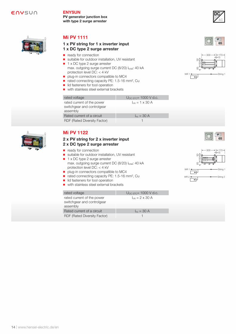
ENYSUN PV generator junction box
with type 2 surge arrester
Mi PV 1111
1 x PV string for 1 x inverter input
1 x DC type 2 surge arrester
ready for connection suitable for outdoor installation, UV resistant 1 x DC type 2 surge arrester
max. outgoing surge current DC (8/20) Itotal: 40 kA
protection level DC: < 4 kV plug-in connectors compatible to MC4 rated connecting capacity PE: 1.5-16 mm², Cu lid fasteners for tool operation with stainless steel external brackets
rated voltage UOC STC= 1000 V d.c.
rated current of the power
switchgear and controlgear
assembly
InA = 1 x 30 A
Rated current of a circuit Inc = 30 A
RDF (Rated Diversity Factor) 1
150
65
30
300 17015
Mi PV 1122
2 x PV string for 2 x inverter input
2 x DC type 2 surge arrester
ready for connection suitable for outdoor installation, UV resistant 1 x DC type 2 surge arrester
max. outgoing surge current DC (8/20) Itotal: 40 kA
protection level DC: < 4 kV plug-in connectors compatible to MC4 rated connecting capacity PE: 1.5-16 mm², Cu lid fasteners for tool operation with stainless steel external brackets
rated voltage UOC STC= 1000 V d.c.
rated current of the power
switchgear and controlgear
assembly
InA = 2 x 30 A
Rated current of a circuit Inc = 30 A
RDF (Rated Diversity Factor) 1
150
65
30
300 17015
DC
AC

| 15
Accessories to reduce condensed water
Canopy
Mi DB ..
Ventilation flange
Mi BF 44
Mi PV 1133
3 x PV string for 3 x inverter input
3 x DC type 2 surge arrester
ready for connection suitable for outdoor installation, UV resistant 1 x DC type 2 surge arrester
max. outgoing surge current DC (8/20) Itotal: 40 kA
protection level DC: < 4 kV plug-in connectors compatible to MC4 rated connecting capacity PE: 1.5-16 mm², Cu lid fasteners for tool operation with stainless steel external brackets
rated voltage UOC STC= 1000 V d.c.
rated current of the power
switchgear and controlgear
assembly
InA = 3 x 30 A
Rated current of a circuit Inc = 30 A
RDF (Rated Diversity Factor) 1
150
65
30
300 17015
ENYSUN PV generator junction box
with type 2 surge arrester
DC
AC
Pressure compensation
element Mi BM x0 G

16 | www.hensel-electric.de/en
ENYSUN PV generator junction box
with type 2 surge arrester
Mi PV 1121
2 x PV string for 1 x inverter input
1 x DC type 2 surge arrester
ready for connection suitable for outdoor installation, UV resistant 1 x DC type 2 surge arrester
max. outgoing surge current DC (8/20) Itotal: 40 kA
protection level DC: < 4 kV plug-in connectors compatible to MC4 rated connecting capacity PE: 1.5-16 mm², Cu lid fasteners for tool operation with stainless steel external brackets
rated voltage UOC STC= 1000 V d.c.
rated current of the power
switchgear and controlgear
assembly
InA = 1 x 30 A
Rated current of a circuit Inc = 15 A
RDF (Rated Diversity Factor) 1
150
65
30
300 17015
Mi PV 1242
4 x PV string for 2 x inverter input
2 x DC type 2 surge arrester
ready for connection suitable for outdoor installation, UV resistant 1 x DC type 2 surge arrester
max. outgoing surge current DC (8/20) Itotal: 40 kA
protection level DC: < 4 kV plug-in connectors compatible to MC4 rated connecting capacity PE: 1.5-16 mm², Cu lid fasteners for tool operation with stainless steel external brackets
rated voltage UOC STC= 1000 V d.c.
rated current of the power
switchgear and controlgear
assembly
InA = 2 x 30 A
Rated current of a circuit Inc = 15 A
RDF (Rated Diversity Factor) 1
65
30
300
300 17015
DC
AC

| 17
Accessories to reduce condensed water
Canopy
Mi DB ..
Ventilation flange
Mi BF 44
Mi PV 1263
6 x PV string for 3 x inverter input
3 x DC type 2 surge arrester
ready for connection suitable for outdoor installation, UV resistant 1 x DC type 2 surge arrester
max. outgoing surge current DC (8/20) Itotal: 40 kA
protection level DC: < 4 kV plug-in connectors compatible to MC4 rated connecting capacity PE: 1.5-16 mm², Cu lid fasteners for tool operation with stainless steel external brackets
rated voltage UOC STC= 1000 V d.c.
rated current of the power
switchgear and controlgear
assembly
InA = 3 x 30 A
Rated current of a circuit Inc = 15 A
RDF (Rated Diversity Factor) 1
65
30
300
300 17015
ENYSUN PV generator junction box
with type 2 surge arrester
DC
AC
Pressure compensation
element Mi BM x0 G

18 | www.hensel-electric.de/en
ENYSUN PV generator junction boxes
with type 2 surge arrester and DC generator disconnect switch
Mi PV 2111
1 x PV string for 1 x inverter input
1 x DC type 2 surge arrester and
1 x DC generator disconnect switch
ready for connection suitable for outdoor installation, UV resistant 1 x DC type 2 surge arrester
max. outgoing surge current DC (8/20) Itotal: 40 kA
protection level DC: < 4 kV 1 x DC generator disconnect switch
utilization catagory for switch disconnectors: DC-21 A =
Switching ohmic loads inclusively moderate overload plug-in connectors compatible to MC4 rated connecting capacity PE: 1.5-16 mm², Cu lid fasteners for tool operation with stainless steel external brackets
rated voltage UOC STC= 1000 V d.c.
rated current of the power
switchgear and controlgear
assembly
InA = 1 x 30 A
Rated current of a circuit Inc = 30 A
RDF (Rated Diversity Factor) 1
65
30
300
150 17015
Mi PV 2222
2 x PV string for 2 x inverter input
2 x DC type 2 surge arrester and
2 x DC generator disconnect switch
ready for connection suitable for outdoor installation, UV resistant 1 x DC type 2 surge arrester
max. outgoing surge current DC (8/20) Itotal: 40 kA
protection level DC: < 4 kV 1 x DC generator disconnect switch
utilization catagory for switch disconnectors: DC-21 A =
Switching ohmic loads inclusively moderate overload plug-in connectors compatible to MC4 rated connecting capacity PE: 1.5-16 mm², Cu lid fasteners for tool operation with stainless steel external brackets
rated voltage UOC STC= 1000 V d.c.
rated current of the power
switchgear and controlgear
assembly
InA = 2 x 30 A
Rated current of a circuit Inc = 30 A
RDF (Rated Diversity Factor) 1
65
30
300
300 17015
DC
AC

| 19
To protect from unauthorized access
Sealing cap
Mi PL 2
Lid lock with locking device
Mi ZS 1x
Lid fastener for tool
operation Mi DR 04
Mi PV 2233
3 x PV string for 3 x inverter input
3 x DC type 2 surge arrester and
3 x DC generator disconnect switch
ready for connection suitable for outdoor installation, UV resistant 1 x DC type 2 surge arrester
max. outgoing surge current DC (8/20) Itotal: 40 kA
protection level DC: < 4 kV 1 x DC generator disconnect switch
utilization catagory for switch disconnectors: DC-21 A =
Switching ohmic loads inclusively moderate overload plug-in connectors compatible to MC4 rated connecting capacity PE: 1.5-16 mm², Cu lid fasteners for tool operation with stainless steel external brackets
rated voltage UOC STC= 1000 V d.c.
rated current of the power
switchgear and controlgear
assembly
InA = 3 x 30 A
Rated current of a circuit Inc = 30 A
RDF (Rated Diversity Factor) 1
65
30
300
300 17015
ENYSUN PV generator junction boxes
with type 2 surge arrester and DC generator disconnect switch
DC
AC

20 | www.hensel-electric.de/en
ENYSUN PV generator junction boxes
with type 2 surge arrester and DC generator disconnect switch
To protect from unauthorized access
Sealing cap
Mi PL 2
Lid lock with locking device
Mi ZS 1x
Lid fastener for tool
operation Mi DR 04
Mi PV 2121
2 x PV string for 1 x inverter input
1 x DC type 2 surge arrester and
1 x DC generator disconnect switch
ready for connection suitable for outdoor installation, UV resistant 1 x DC type 2 surge arrester
max. outgoing surge current DC (8/20) Itotal: 40 kA
protection level DC: < 4 kV 1 x DC generator disconnect switch
utilization catagory for switch disconnectors: DC-21 A =
Switching ohmic loads inclusively moderate overload plug-in connectors compatible to MC4 rated connecting capacity PE: 1.5-16 mm², Cu lid fasteners for tool operation with stainless steel external brackets
rated voltage UOC STC= 1000 V d.c.
rated current of the power
switchgear and controlgear
assembly
InA = 1 x 30 A
Rated current of a circuit Inc = 15 A
RDF (Rated Diversity Factor) 1
65
30
300
150 17015
Mi PV 2242
4 x PV string for 2 x inverter input
2 x DC type 2 surge arrester and
2 x DC generator disconnect switch
ready for connection suitable for outdoor installation, UV resistant 1 x DC type 2 surge arrester
max. outgoing surge current DC (8/20) Itotal: 40 kA
protection level DC: < 4 kV 1 x DC generator disconnect switch
utilization catagory for switch disconnectors: DC-21 A =
Switching ohmic loads inclusively moderate overload plug-in connectors compatible to MC4 rated connecting capacity PE: 1.5-16 mm², Cu lid fasteners for tool operation with stainless steel external brackets
rated voltage UOC STC= 1000 V d.c.
rated current of the power
switchgear and controlgear
assembly
InA = 2 x 30 A
Rated current of a circuit Inc = 15 A
RDF (Rated Diversity Factor) 1
65
30
300
300 17015
DC
AC

| 21
Mi PV 2263
6 x PV string for 3 x inverter input
3 x DC type 2 surge arrester and
3 x DC generator disconnect switch
ready for connection suitable for outdoor installation, UV resistant 1 x DC type 2 surge arrester
max. outgoing surge current DC (8/20) Itotal: 40 kA
protection level DC: < 4 kV 1 x DC generator disconnect switch
utilization catagory for switch disconnectors: DC-21 A =
Switching ohmic loads inclusively moderate overload plug-in connectors compatible to MC4 rated connecting capacity PE: 1.5-16 mm², Cu lid fasteners for tool operation with stainless steel external brackets
rated voltage UOC STC= 1000 V d.c.
rated current of the power
switchgear and controlgear
assembly
InA = 3 x 30 A
Rated current of a circuit Inc = 15 A
RDF (Rated Diversity Factor) 1
65
30
300
300 17015
ENYSUN PV generator junction boxes
with type 2 surge arrester and DC generator disconnect switch
DC
AC

22 | www.hensel-electric.de/en
ENYSUN PV generator junction boxes
with type 1 + 2 surge arrester
Mi PV 1171 NEW
2 x PV string for 1 x inverter input
1 x DC type 1 + 2 surge arrester
ready for connection suitable for outdoor installation, UV resistant DC type 1 + 2 surge arrester
lightning surge current DC (10/350) [DC+/DC -> PE] Iimp: 12.5 kA
protection level [DC+/DC- -> PE]: < 2,5 kV plug-in connectors compatible to MC4 rated connecting capacity PE: 1.5-25 mm², Cu lid fasteners for tool operation with stainless steel external brackets
rated voltage UOC STC= 1000 V d.c.
rated current of the power
switchgear and controlgear
assembly
InA = 1 x 30 A
Rated current of a circuit Inc = 15 A
RDF (Rated Diversity Factor) 1
65
30
30
0
150 17015
DC
AC
| 23
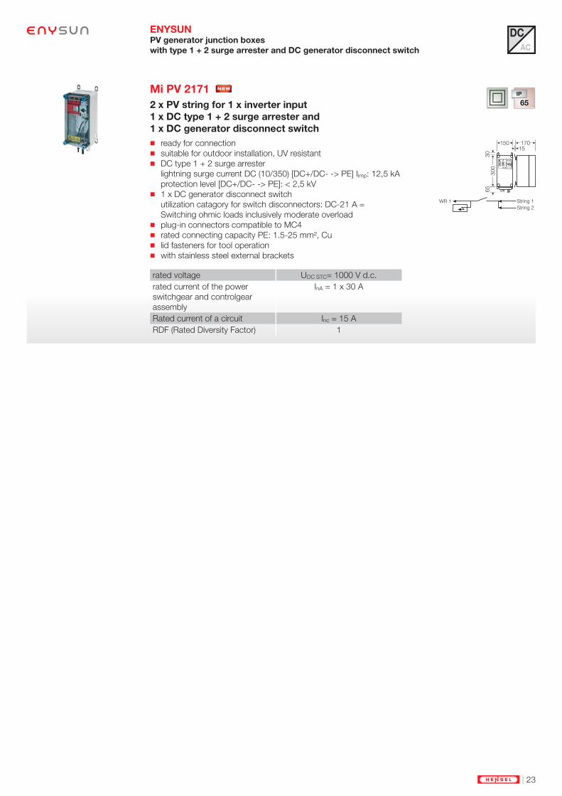
ENYSUN PV generator junction boxes
with type 1 + 2 surge arrester and DC generator disconnect switch
Mi PV 2171 NEW
2 x PV string for 1 x inverter input
1 x DC type 1 + 2 surge arrester and
1 x DC generator disconnect switch
ready for connection suitable for outdoor installation, UV resistant DC type 1 + 2 surge arrester
lightning surge current DC (10/350) [DC+/DC- -> PE] Iimp: 12,5 kA
protection level [DC+/DC- -> PE]: < 2,5 kV 1 x DC generator disconnect switch
utilization catagory for switch disconnectors: DC-21 A =
Switching ohmic loads inclusively moderate overload plug-in connectors compatible to MC4 rated connecting capacity PE: 1.5-25 mm², Cu lid fasteners for tool operation with stainless steel external brackets
rated voltage UOC STC= 1000 V d.c.
rated current of the power
switchgear and controlgear
assembly
InA = 1 x 30 A
Rated current of a circuit Inc = 15 A
RDF (Rated Diversity Factor) 1
65
30
30
0
150 17015
DC
AC

24 | www.hensel-electric.de/en
ENYSUN PV generator junction boxes
with string overload and DC generator disconnect switch
Mi PV 3311
6 x PV string for 1 x inverter input
2 x DC generator disconnect switch
ready for connection suitable for outdoor installation, UV resistant 6 holder for fuses each + and -
connection: 1.5-16 mm² Cu 2 x DC Generator disconnect switch
Utilization category for switch disconnectors: DC-21A = Switching
ohmic loads inclusively moderate overload connection: 6-35 mm², Cu lid fasteners for tool operation included cable entry: 12 x AKM 16, 2 x AKM 25 with stainless steel external brackets
rated voltage UOC STC= 1000 V d.c.
rated current of the power
switchgear and controlgear
assembly
InA = 60 A
Rated current of a circuit Inc = 10 A
RDF (Rated Diversity Factor) 1
30
325
450 17015
Mi PV 3321
6 x PV string for 1 x inverter input
1 x DC type 2 surge arrester and
2 x DC generator disconnect switch
ready for connection suitable for outdoor installation, UV resistant 6 holder for fuses each + and -
connection: 1.5-16 mm² Cu 2 x DC Generator disconnect switch
Utilization category for switch disconnectors: DC-21A = Switching
ohmic loads inclusively moderate overload connection: 6-35 mm², Cu 1 x DC type 2 surge arrester
max. outgoing surge current DC (8/20) Itotal: 40 kA
protection level DC: < 4 kV rated connecting capacity PE: 1.5-35 mm², Cu lid fasteners for tool operation included cable entry: 12 x AKM 16, 3 x AKM 25 with stainless steel external brackets
rated voltage UOC STC= 1000 V d.c.
rated current of the power
switchgear and controlgear
assembly
InA = 60 A
Rated current of a circuit Inc = 10 A
RDF (Rated Diversity Factor) 1
30
325
450 17015
DC
AC
| 25
Accessories to reduce condensed water
Canopy
Mi DB ...
Ventilation flange
Mi BF 44
Mi PV 3611
12 x PV string for 1 x inverter input
1 x DC generator disconnect switch
ready for connection for each 12 fuse holders + and -
connection: 1.5-16 mm² Cu 1 x DC Generator disconnect switch
connection: M 10 (max. 1 x 120 mm² per pole) lid fasteners for tool operation included cable entry: 12 x AKM 16, 12 x AKM 20, 2 x AKM 25 with stainless steel external brackets
rated voltage UOC STC= 1000 V d.c.
rated current of the power
switchgear and controlgear
assembly
InA = 120 A
Rated current of a circuit Inc = 10 A
RDF (Rated Diversity Factor) 1
30
600 17015
450
ENYSUN PV generator junction boxes
with string overload and DC generator disconnect switch
Mi PV 3621
12 x PV string for 1 x inverter input
1 x DC type 2 surge arrester and
1 x DC generator disconnect switch
ready for connection for each 12 fuse holders + and -
connection: 1.5-16 mm² Cu 1 x DC Generator disconnect switch
connection: M 10 (max. 1 x 120 mm² per pole) 1 x DC type 2 surge arrester
max. outgoing surge current DC (8/20) Itotal: 40 kA
protection level DC: < 4 kV rated connecting capacity PE: 1.5-35 mm², Cu lid fasteners for tool operation included cable entry: 12 x AKM 16, 12 x AKM 20, 3 x AKM 25 with stainless steel external brackets
rated voltage UOC STC= 1000 V d.c.
rated current of the power
switchgear and controlgear
assembly
InA = 120 A
Rated current of a circuit Inc = 10 A
RDF (Rated Diversity Factor) 1
30
450
600 17015
DC
AC
Pressure compensation
element Mi BM x0 G

26 | www.hensel-electric.de/en
Mi PV 3931
24 x PV string for 1 x inverter input
1 x DC generator disconnect switch
ready for connection for each 24 fuse holders + and -
connection: 1.5-16 mm² Cu 1 x DC Generator disconnect switch
connection: M 10 (max. 1 x 120 mm² per pole) lid fasteners for tool operation included cable entry: 24 x AKM 16, 24 x AKM 20, 2 x AKM 40 with stainless steel external brackets
rated voltage UOC STC= 1000 V d.c.
rated current of the power
switchgear and controlgear
assembly
InA = 240 A
Rated current of a circuit Inc = 10 A
RDF (Rated Diversity Factor) 1
30
475
17015
900
ENYSUN PV generator junction boxes
with string overload and DC generator disconnect switch
Accessories to reduce condensed water
Canopy
Mi DB ...
Ventilation flange
Mi BF 44
Mi PV 3941
24 x PV string for 1 x inverter input
1 x DC type 2 surge arrester and
1 x DC generator disconnect switch
ready for connection for each 24 fuse holders + and -
connection: 1.5-16 mm² Cu 1 x DC Generator disconnect switch
connection: M 10 (max. 1 x 120 mm² per pole) 1 x DC type 2 surge arrester
max. outgoing surge current DC (8/20) Itotal: 40 kA
protection level DC: < 4 kV rated connecting capacity PE: 1.5-35 mm², Cu lid fasteners for tool operation included cable entry: 24 x AKM 16, 25 x AKM 20, 2 x AKM 40 with stainless steel external brackets
rated voltage UOC STC= 1000 V d.c.
rated current of the power
switchgear and controlgear
assembly
InA = 240 A
Rated current of a circuit Inc = 10 A
RDF (Rated Diversity Factor) 1
30
475
17015
900
DC
AC
| 27
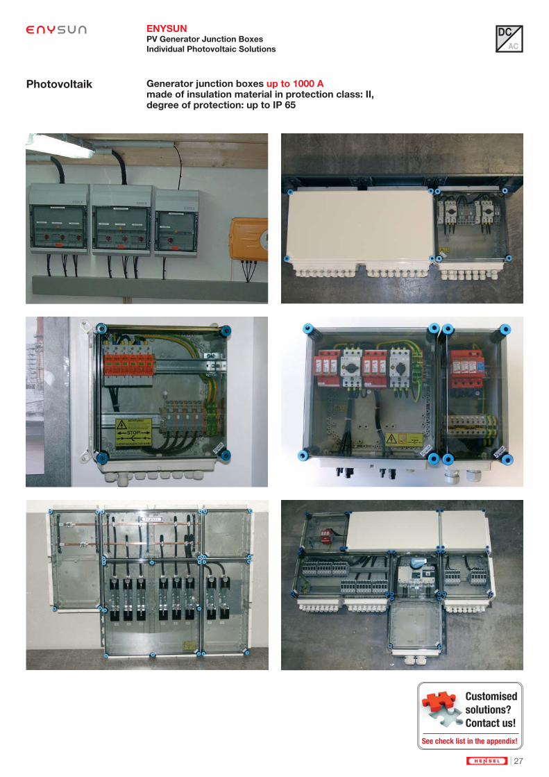
ENYSUN PV Generator Junction Boxes
Individual Photovoltaic Solutions
DC
AC
Generator junction boxes up to 1000 Amade of insulation material in protection class: II,degree of protection: up to IP 65
Photovoltaik
Customised
solutions?
Contact us!
See check list in the appendix!

28 | www.hensel-electric.de/en
Solar Inverter Collectors
Complete set:
pre-fabricated and tested solar inverter
collector solutions
Electrical data:
Rated voltage: 230/400 V a.c.
Rated capacity: up to 220 kVA
Degree of protection: up to IP 65
optional with surge arrester r
Derating:
Taking account of the thermal effects
in generating plants, spacers ensure
ventilation and degree of protection
IP 2X
ENYSUN
���
�� �� �� ��
��
��
���
Solar inverter
Solar inverter
collector
Distribution board
Solar modules
PV Generator
junction box
Grid 230/400V a.c.

| 29
DC
AC
EMC compliant busbar
The busbar system comes standard with N/PEN conductors in the phase conductor
area. The N busbars have the same current carrying capacity as the phase conductor.
These busbars are appropriate for:
- Harmonics created by the solar inverter.
- Unbalanced loads (Unbalanced load limit 4.6 kVA allowed by power supply compa-
nies) created by power supply companies.
Connection of large cable cross-sections
By using a cable insert in combination with strain relief for inverter-collectors from
140 kVA an easy connection of large cable cross-sections is possible.
When using a cable insertion the cables are inserted from the front. As a result, cables
must not be inserted via cable glands.
To obtain degree of protection the strain relief keeps the cables connected centred
within the stepped grommet. In addition, the cables are strain- and pressure relieved.

30 | www.hensel-electric.de/en
ENYSUN Solar Inverter Collectors
DC
AC
Solar inverter collector
supplied as set
PV inverter collectors are
supplied as a complete set.
All necessary parts are put
together in one set.
The individual housings are
ready for connection and
tested. They can be moun-
ted to distribution boards, in
order to realize a customized
assembly according to the
individual locations.
PV inverter collectors can be
extended with lightning or
surge protection and residual
current protection (RCD)
basing on pre-engineered
enclosure solutions, thus
offering optimal solutions for
all requirements.
| 31
ENYSUN Solar Inverter Collectors
DC
AC
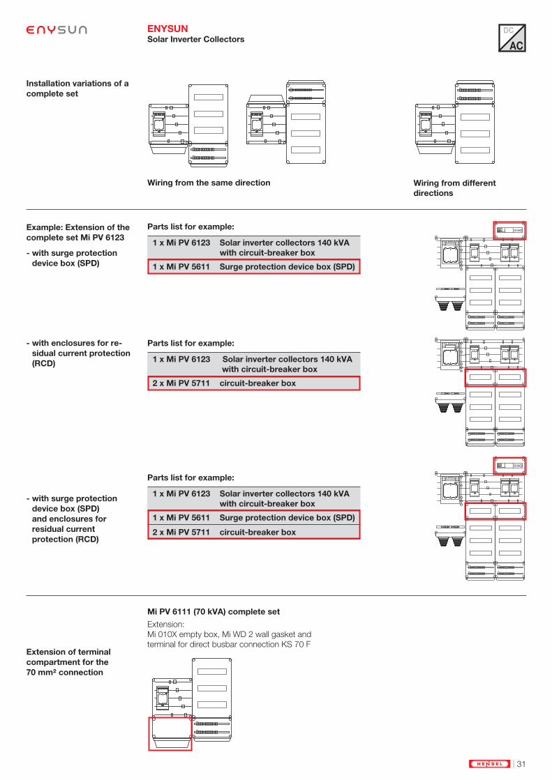
Installation variations of a
complete set
Example: Extension of the
complete set Mi PV 6123
- with surge protection
device box (SPD)
- with enclosures for re-
sidual current protection
(RCD)
- with surge protection
device box (SPD)
and enclosures for
residual current
protection (RCD)
Extension of terminal
compartment for the
70 mm² connection
Wiring from the same direction Wiring from different
directions
Mi PV 6111 (70 kVA) complete set
Extension:
Mi 010X empty box, Mi WD 2 wall gasket and
terminal for direct busbar connection KS 70 F
Parts list for example:
Parts list for example:
Parts list for example:
1 x Mi PV 6123 Solar inverter collectors 140 kVA
with circuit-breaker box
1 x Mi PV 5611 Surge protection device box (SPD)
1 x Mi PV 6123 Solar inverter collectors 140 kVA
with circuit-breaker box
2 x Mi PV 5711 circuit-breaker box
1 x Mi PV 6123 Solar inverter collectors 140 kVA
with circuit-breaker box
1 x Mi PV 5611 Surge protection device box (SPD)
2 x Mi PV 5711 circuit-breaker box

32 | www.hensel-electric.de/en
ENYSUN Solar Inverter Collectors
with Circuit-breaker Box
DC
AC
Photovoltaic installations need special ratings.
Why are special solutions needed for PV plants?
The rating of photovoltaic installations differs signifi cantly from normal building installations in that the
installed devices are subject to a continuous load.
Protective device
selection
Applying the simultaneity
factor
Infl uenced by heat from
the simultaneity factor
and load
Power distribution in
photovoltaic plants
Protective device selection and rating to protect
cables related to the current resp. load of the solar
inverter on the
AC side.
Select protective devices in the form of a fuse or
miniature circuit breaker.
PV plants have a simultaneity factor of 1!
Which is why the distribution boards in PV plants
have to be dimensioned differently and not simply
according to the number of modules.
Constant high loads lead to high average power
dissipation during the energy production phase.
Power dissipation therefore needs to be reduced
to the point where the maximum temperature for
devices is not exceeded.
Power distribution
in buildings
Protective device selection and rating to protect
cables related to the current resp. the load of the
consumer.
Select protective devices in the form of a fuse or
miniature circuit breaker.
Due to the low simultaneity factor, the installed
distribution board is often dimensioned according
to the number of modules.
In consumption plants, power dissipation fl uctu-
ates depending on the number of consumers
switched on at any one time.
Low average effective power dissipation
���������������� ���� ���
���
������ ���� ������Power loss Pv
Ø effective power loss
time
���������������� ���� ���
���
������ ���� ������Power loss Pv
Ø effective power loss
time
�
!
�
!

| 33
ENYSUN Solar Inverter Collectors
with Circuit-breaker Box
DC
AC
Hensel solar inverter collectors correct dimensioned and tested: e.g. circuit-breaker boxHigh power dissipation levels can lead to exceeding the maximum permitted temperature for devices meaning that protection devices can
trip even when beneath rated current levels.
Photovoltaic installations require a special way of thinking about device dimensioning and selection!
The equipment of a circuit breaker box can be inferred from the following table.
2. Standard assembly support1. Assessing simultaneity and load capacity
High simultaneity and load:
Devices spaced apart allow a better radiation of the power
dissipation.
Additional slots assure increased air circulation in the
enclosure.
The larger enclosure increase the dissipated power loss.
Installation devices are to be properly installed automatically
with the help of spacers.
At the same time the miniature circuit breaker is in the proper
position relative to the cover plate.
Table: Rating of solar inverter collector
Protection device for 1~ solar inverter with 1-pole miniature circuit breakers (MCB) *1 MU = 18 mm
Inverter miniature circuit breaker cable glands fl ange
maximum power output:
max. operating current
rated current max. quantity
MU* between two MCB
minimum cable cross section
minimum out-side diameter
2,8 kVA 12 A 16 A 6 per row 1 3 x 2,5 mm² 11 mm M 25 Mi FM 25
3,7 kVA 16 A 20 A 5 per row 1 3 x 2,5 mm² 11 mm M 25 Mi FM 25
4,8 kVA 21 A 25 A 4 per row 1 3 x 4 mm² 13 mm M 25 Mi FM 25
6,5 kVA 28 A 32 A 3 per row 1 3 x 6 mm² 15 mm M 25 Mi FM 25
Values are valid for max. ambient temperature of 35° C
Protection device for 3~ solar inverter with 1-pole miniature circuit breakers (MCB) *1 MU = 18 mm
Inverter miniature circuit breaker cable glands fl ange
maximum power output:
max. operating current
rated current max. quantity
MU* between two MCB
minimum cable cross section
minimum out-side diameter
8,4 kVA 12 A 16 A 6 per row 1 5 x 2,5 mm² 13,5 mm M 25 Mi FM 32
11,1 kVA 16 A 20 A 5 per row 1 5 x 2,5 mm² 13,5 mm M 25 Mi FM 32
14,4 kVA 21 A 25 A 4 per row 1 5 x 4 mm² 15,5 mm M 32 Mi FM 32
19,5 kVA 28 A 32 A 3 per row 1 5 x 6 mm² 18 mm M 32 Mi FM 32
Protection device for 3~ solar inverter with 3-pole miniature circuit breakers (MCB) *1 MU = 18 mm
Inverter miniature circuit breaker cable glands fl ange
maximum power output:
max. operating current
rated current max. quantity
MU* between two MCB
minimum cable cross section
minimum out-side diameter
8,4 kVA 12 A 16 A 2 per row 6 5 x 2,5 mm² 13,5 mm M 25 Mi FM 32
8,9 kVA 13 A 20 A 2 per row 66 5 x 2,5 mm² 13,5 mm M 25 Mi FM 32
11,7 kVA 17 A 25 A 2 per row 12 5 x 4 mm² 15,5 mm M 32 Mi FM 32
14,4 kVA 21 A 25 A 1 per row 5 x 4 mm² 15,5 mm M 32 Mi FM 32
19,5 kVA 28 A 32 A 1 per row 5 x 6 mm² 18 mm M 32 Mi FM 32

34 | www.hensel-electric.de/en
ENYSUN Solar inverter collectors
with circuit-breaker box
Mi PV 6111
Rated capacity: 70 kVA
complete enclosure set, not assembled incoming cables: for inverters up to 6.4 kVA, 1~ or 19.3 kVA, 3~
rated operating current 28 A per inverter max. 18 x 1~ inverters or 6 x 3~ inverters maximum quantity and ratings of MCBs according to
table ”Rating of PV solar inverter collector“ connection: 1.5-16 mm², Cu 18 terminals per PE+N outgoing: switch disconnector, 3 pole with knife links
connection: 35 mm², Cu
1 terminal per PE+N for copper conductors outgoing cable changeable above or below maximum back-up fuse depending on the miniature circuit
breakers used (manufacturer specifications) order cable entries separately with stainless steel external brackets
rated voltage Un = 230/400 V a.c.
rated current of the power
switchgear and controlgear
assembly
InA = 100 A
N
PE
30
600 17015
450
N
PE
Mi PV 6123
Rated capacity: 140 kVA
complete enclosure set, not assembled incoming cables: for inverters up to 6.4 kVA, 1~ or 19.3 kVA, 3~
rated operating current 28 A per inverter max. 36 x 1~ inverters or 12 x 3~ inverters maximum quantity and ratings of MCBs according to
table ”Rating of PV solar inverter collector“ connection: 1.5-16 mm², Cu 36 terminals per PE+N outgoing: switch disconnector, 3 pole with knife links
connection: M 10 (max. 1 x 240 mm² per phase)
1 terminal per PE+N for copper conductors outgoing cable changeable above or below order cable entries separately with stainless steel external brackets
rated voltage Un = 230/400 V a.c.
rated current of the power
switchgear and controlgear
assembly
InA = 200 A
N
PE
30
900 17015
925
N
PE
N
PE
N
PE
DC
AC

| 35
ENYSUN Solar inverter collectors
with circuit-breaker box
Extension boxes for solar inverter collectors, see accessories
Mi PV 5611
Surge protection device
box (SPD)
Mi PV 5621
Surge protection device
box (SPD)
Mi PV 5711
12 modules: 1 x 12 x 18 mm
Mi PV 6544
Rated capacity: 220 kVA
complete enclosure set, not assembled incoming cables: for inverters up to 6.4 kVA, 1~ or 19.3 kVA, 3~
rated operating current 28 A per inverter max. 72 x 1~ inverters or 24 x 3~ inverters maximum quantity and ratings of MCBs according to
table ”Rating of PV solar inverter collector“ connection: 1.5-16 mm², Cu 72 terminals per PE+N outgoing: switch disconnector, 3 pole with knife links
connection: M 10 (max. 1 x 240 mm² per phase)
1 terminal per PE+N for copper conductors outgoing cable changeable above or below order cable entries separately with mounting profiles
rated voltage Un = 230/400 V a.c.
rated current of the power
switchgear and controlgear
assembly
InA = 320 A
1586
17062
1335
N
PE
N
PE
N
PE
N
PE
N
PE
N
PE
N PE
N
PE
DC
AC

36 | www.hensel-electric.de/en
ENYSUN Solar inverter collectors
with switch disconnectors for D 02 fuses 63 A
Mi PV 5311
Rated capacity: 70 kVA
for 3~ inverters
complete enclosure set, not assembled incoming cables: for inverters up to 33 kVA, 3~
rated operating current AC 48 A per inverter 3 x 63 A, 3-pole, D0 2
1 or 3-pole switching
rated connecting capacity: solid(sol) 1.5-6 mm², flexible(f)
1.5-16 mm², Cu 3 terminals per PE+N outgoing: switch disconnector, 3 pole with knife links
connection: 70 mm², Cu
1 terminal per PE+N for copper conductors outgoing cable changeable above or below order cable entries separately with stainless steel external brackets
rated voltage Un = 230/400 V a.c.
rated current of the power
switchgear and controlgear
assembly
InA = 100 A
Rated current of a circuit Inc = 48 A
RDF (Rated Diversity Factor) 1
30
60015
475
170
N
PE
Mi PV 5323
Rated capacity: 140 kVA
for 3~ inverters
complete enclosure set, not assembled incoming cables: for inverters up to 33 kVA, 3~
rated operating current AC 48 A per inverter 6 x 63 A, 3-pole D0 2
1- or 3-pole switching
rated connecting capacity: solid (sol) 1.5-6 mm², flexible (f)
1.5-16 mm², Cu 6 terminals per PE+N outgoing: switch disconnector, 3 pole with knife links
connection: M 10 (max. 1 x 240 mm² per phase)
1 terminal per PE+N for copper conductors outgoing cable changeable above or below order cable entries separately with stainless steel external brackets
rated voltage Un = 230/400 V a.c.
rated current of the power
switchgear and controlgear
assembly
InA = 200 A
Rated current of a circuit Inc = 48 A
RDF (Rated Diversity Factor) 1
30
90015
735
N
PE
214
DC
AC

| 37
ENYSUN Solar inverter collectors
with switch disconnectors for D 02 fuses 63 A
Extension boxes for solar inverter collectors, see accessories
Mi PV 5611
Surge protection device
box (SPD)
Mi PV 5621
Surge protection device
box (SPD)
Mi PV 5711
12 modules: 1 x 12 x 18 mm
Mi PV 5341
Rated capacity: 220 kVA
for 3~ inverters
complete enclosure set, not assembled incoming cables: for inverters up to 33 kVA, 3~
rated operating current AC 48 A per inverter 9 x 63 A, 3-pole D0 2
1- or 3-pole switching
rated connecting capacity: solid (sol) 1.5-6 mm²,
flexible (f) 1.5-16 mm², Cu 9 terminals per PE+N outgoing: switch disconnector, 3 pole with knife links
connection: M 10 (max. 1 x 240 mm² per phase)
1 terminal per PE+N for copper conductors outgoing cable changeable above or below order cable entries separately with mounting profiles
rated voltage Un = 230/400 V a.c.
rated current of the power
switchgear and controlgear
assembly
InA = 320 A
Rated current of a circuit Inc = 48 A
RDF (Rated Diversity Factor) 1
17062
1335
N
PE
N PE
1286
DC
AC

38 | www.hensel-electric.de/en
ENYSUN Boxes with electrical function
for the assembly of solar inverter collectors
Mi PV 1318
18 modules: 3 x 6 x 18 mm
without PE and N terminal
3-row for installation of DIN rail equipment in accordance with DIN 43880 maximum quantity and ratings of MCBs and flange selection
according to table ”Rating of PV solar inverter collector“ with blanking strips for unused DIN rail openings lid fasteners for hand operation
300 170
450
1xM32/403xM40/50
1xM20, 4xM251xM32/403xM40/50
2xM20,10xM251xM32/40
2xM2010xM25,1xM32/40
Mi 1335
36 modules: 3 x 12 x 18 mm
without PE and N terminal
3-row for installation of DIN rail equipment in accordance with DIN 43880 order PE/N terminals separately with blanking strips for unused DIN rail openings lid fasteners for hand operation
300 170
450
1xM32/403xM40/50
1xM20, 4xM251xM32/403xM40/50
2xM20,10xM251xM32/40
2xM2010xM25,1xM32/40
M ore empty enclosures or enclosure with electrical function :
DC
AC
- see Hensel website: www.hensel-electric.de
- see Hensel International Catalogue

| 39
ENYSUN Boxes with electrical function
for the assembly of solar inverter collectors
Mi 3266
with switch disconnectors with fuses
Rated current of busbars 250 A
only for combination
3 x 63 A, 3-pole, D0 2
1 or 3-pole switching
rated connecting capacity: solid(sol) 1.5-6 mm², flexible(f)
1.5-16 mm², Cu per PE and N terminal: 3 x 1.5-16 mm², Cu, round conductors N conductor with the same current carrying capacity as the phase
conductors lid fasteners for hand operation
rated voltage Un = 400 V a.c.
Rated current of a circuit Inc = 50.4 A
Number of circuits 3
rated short-time withstand
current
Icw = 15 kA / 1 s
busbar system - polarity 5
busbar thickness L1-L3: 10 mm
N, PE: 5 mm
centreline spacing of busbars 60 mm
300 170
300
4xM253xM40/50
4xM253xM40/50
2xM2010xM25
1xM32/40
2xM2010xM25
1xM32/40
Mi 3267
with switch disconnectors with fuses
Rated current of busbars 400 A
only for combination
3 x 63 A, 3-pole, D0 2
1 or 3-pole switching
rated connecting capacity: solid(sol) 1.5-6 mm², flexible(f)
1.5-16 mm², Cu per PE and N terminal: 3 x 1.5-16 mm², Cu, round conductors N conductor with the same current carrying capacity as the phase
conductors lid fasteners for hand operation
rated voltage Un = 400 V a.c.
Rated current of a circuit Inc = 50.4 A
Number of circuits 3
rated short-time withstand
current
Icw = 15 kA / 1 s
busbar system - polarity 5
busbar thickness L1-L3, N: 10 mm
PE: 5 mm
centreline spacing of busbars 60 mm
300 170
300
4xM253xM40/50
4xM253xM40/50
2xM2010xM25
1xM32/40
2xM2010xM25
1xM32/40
DC
AC

40 | www.hensel-electric.de/en
Mi PV 5511
Terminal box
extension set ready for connection with wall gasket per PE+N 12 x 1.5-16 mm², Cu, 1 x 4-35 mm², Cu with 100 A wiring between PE+N terminals and busbar lid fasteners for tool operation Separately order flange for cable entry.
rated voltage Un = 230/400 V a.c.
300 170
150
N
PE
2xM202xM2010xM25
1xM32/40
2xM202xM2010xM25
1xM32/40
ENYSUN Boxes with electrical function
for the assembly of solar inverter collectors
Mi PV 5521
Terminal box
extension set ready for connection with wall gasket terminals per PE+N:
9 x 1.5-16 mm², Cu
1 x 4-35 mm², Cu with 100 A wiring between PE+N terminals and busbar lid fasteners for tool operation Separately order flange for cable entry.
rated voltage Un = 230/400 V a.c.
300 170
300
N
PE
4xM253xM40/50
4xM253xM40/50
DC
AC
M ore empty enclosures or enclosure with electrical function :
- see Hensel website: www.hensel-electric.de
- see Hensel International Catalogue

| 41
ENYSUN Solar Inverter Collectors
als individuelle Lösungen
Solar inverter collectors up to 560 kVA
made of insulation material, protection class II,
degree of protection up to IP 65
Photovoltaik
DC
AC
Customised
solutions?
Contact us!
See check list in the appendix!

42 | www.hensel-electric.de/en
Disconnetion switch
ENYSUN
Solar inverter
Solar inverter
collector
Disconnetion
switch
Solar modules
PV Generator
junction box
Netz 230/400 V a.c.Grid 230/400 V a.c.

| 43
Disconnetion switch
Connection of generation systems in accordance with
application guide VDE-AR-N 4105
Distribution board with grid and
system protection and two switches
completely assembled and
ready for connection
integration of the simplyfi ed
feed-in management

44 | www.hensel-electric.de/en
ENYSUN
Accessories

| 45
ENYSUN Solar inverter collectors
Extension boxes
Mi PV 5611
Surge protection device box (SPD)
1 x AC type 2 surge arrester
extension set with wall gasket with pre-assembled connecting cables with terminals for direct connection on busbar with fuse bases 63 A, Neozed 1 x AC type 2 surge arrester
max. outgoing surge current AC (8/20) Itotal: 40 kA
protection level AC: < 2,5 kV
defect display for 3-phase TN lid fasteners for hand operation Connection
rated voltage Un = 230/400 V a.c.
300 170
150
1xM201xM32/40
1xM201xM32/40
2xM2010xM25
1xM32/401xM32/40
2xM2010xM25
1xM32/40
Mi PV 5621
Surge protection device box (SPD)
1 x AC type 1 surge arrester
extension set with wall gasket with pre-assembled connecting cables with fuse switch disconnectors HRC 00, 3-pole
with fuse links 3 x 160 A AC type 1 surge arrester
lightning surge current AC(10/350) [L+N -> PE] Iimp: 100 kA
protection level AC: < 4 kV
defect display for 3-phase TN lid fastener for tool operation Connection
rated voltage Un = 230/400 V a.c.
300 170
300
3xM40/504xM25
3xM40/50
2xM2010xM25
1xM32/401xM32/40
2xM2010xM25
1xM32/40
Mi PV 5711
12 modules: 1 x 12 x 18 mm
1-row without PE and N terminal for installation of DIN rail equipment in accordance with DIN
43880 with blanking strips for unused DIN rail openings with wall gasket lid fasteners for hand operation
300 170
150
1xM201xM32/40
1xM201xM32/40
2xM2010xM25
1xM32/401xM32/40
2xM2010xM25
1xM32/40

46 | www.hensel-electric.de/en
ENYSUN Accessories
terminals for direct connection on busbar for sonductors and laminated wiring strip
Remarks: For observance of insulation resistance clearances of 10 mm are necessary between different potentials and of 15 mm between
conductive metal parts.
* Aluminium conductors must be prepared prior to connection in accordance with the relevant technical recommendation
Type conductor cross
section
type of cable wiring strip for busbars width
KS 16 F 1.5-16 mm2Cu - ... x 5 mm 11 mm
KS 16 Z 1.5-16 mm2Cu - ... x 10 mm 11 mm
KS 35 F 4-35 mm2Cu 100 A: Mi VS 100
160 A: Mi VS 160
... x 5 mm 16 mm
KS 35 Z 4-35 mm2 Cu 100 A: Mi VS 100
160 A: Mi VS 160
... x 10 mm 16 mm
KS 70 F 10-70 mm2Cu 100 A: Mi VS 100
160 A: Mi VS 160
... x 5 mm 21 mm
KS 70 Z 10-70 mm2Cu 100 A: Mi VS 100
160 A: Mi VS 160
... x 10 mm 21 mm
KS 120 F 25-120 mm2 Cu 250 A: Mi VS 250
400 A: Mi VS 400
... x 5 mm 25 mm
KS 120 Z 25-120 mm2 Cu 250 A: Mi VS 250
400 A: Mi VS 400
... x 10 mm 25 mm
KS 240/12 Cu 35-240 mm2
Alu 35-185 mm2
Cu / Alu* - 12 x 5 mm /
12 x 10 mm
34 mm
KS 150 35-150 mm2 Cu 630 A: Mi VS 630 12 x 5 mm /
12 x 10 mm
34 mm
KS 185 95-185 mm2 Cu/Alu* - 20 x 10 mm /
25 x 10 mm /
30 x 10 mm
38 mm
KS 240 V - - 630 A: Mi VS 630 20 x 10 mm /
25 x 10 mm /
30 x 10 mm
38 mm
KS 300 120-300 mm2 Cu/Alu* - 20 x 10 mm /
25 x 10 mm /
30 x 10 mm
38 mm

| 47
ENYSUN Accessories
250 AN: 12x5
L1-L3: 12x10
PE: 12x5
400 AN: 12x10
L1-L3: 20x10
PE: 12x5
630 AN: 25x10
L1-L3: 30x10
PE: 12x10
250 AN: 12x5
L1-L3: 12x10
PE: 12x5
400 AN: 12x10
L1-L3: 20x10
PE: 12x5
630 AN: 25x10
L1-L3: 30x10
PE: 12x10
250 AN: 12x5
L1-L3: 12x10
PE: 12x5
400 AN: 12x10
L1-L3: 20x10
PE: 12x5
630 AN: 25x10
L1-L3: 30x10
PE: 12x10
1) "
�#
1)
�#
"
�#
����
�#
����"
�# �#
$�
$�$�
$�
$�$�
"$�
$�$�
"
�#
���� $�
$�$�
���� $�
$�$�
"���� $�
$�$�
"
�#
$�
$�$�
"
$�$�$�
"
$�$�$�
�#
1) "
�#
1)
�#
1) "
�#
����
1)
�#
����"
�# �#
1)$�
$�$�
1)$�
$�$�
" 1)$�
$�$�
"
�#
���� $�
$�$�
���� $�
$�$�
"���� $�
$�$�
"
�#
$�
$�$�
"
$�$�$�
"
$�$�$�
�#
1) "
�#
1)
�#
"
�#
����
�#
����"
�# �#
1)$�
$�$�
1)$�
$�$�
" 1)$�
$�$�
"
�#
���� $�
$�$�
���� $�
$�$�
"���� $�
$�$�
"
�#
$�
$�$�
"
$�$�$�
"
$�$�$�
�#
1) "
�#
����
1)
�#
����"
�# �#
1)���� $�
$�$�
1)���� $�
$�$�
" 1)���� $�
$�$�
"
�#
$�
$�$�
"
$�$�$�
"
$�$�$�
�#
"$�$�$��#
"
�# �#
"$�$�$��#
"
�# �#
$�
$�$�
"
$�$�$�
$�
$�$�
"
$�$�$�
$�
$�$�
"
$�$�$�
Mi fuse boxes Diazed/Neozed Mi HRC fuse boxes, fuse bases and fuse
switch disconnector
Mi busbar boxes
����
�������� ����
1) Terminals in the delivery of the functional boxes, see technical descriptions.
International abbreviations: type of cable
r (rigid) f (fl exible)
with gas-tight end ferrulesol (solid) s (stranded)
round conductors sector-type conductors round conductors sector-type conductors

48 | www.hensel-electric.de/en
ENYSUN Accessories for PV solar inverter collectors
DA 240
Terminal for direct connection up to 400 A
max. 240 mm²
for mounting onto switchgear with flat contact M10 with insulating cover rated connecting capacity:
35-70 mm² s (round),Cu/Alu
50-185 mm² s (sector), Cu/Alu
35-50 mm² sol, Cu/Alu
70-240 mm² sol (sector) Cu/Alu before connecting, aluminum conductors must be pre-treated
according to the appropriate technical recommendations, see
technical information aluminum conductors
tightening torque for terminal 22,0 Nm
MS NH 00
Fuse switch disconnector 160 A, HRC 00, 3-pole
for retrofitting on busbars
for the exchange and complement in Mi fuse boxes height: 200 mm x width: 106 mm Connection: 1.5-70 mm², Cu, round conductor
Connection of wiring strip Mi VS 100/160
rated voltage Un = 690 V a.c.
busbar thickness 10 mm
centreline spacing of busbars 60 mm
tightening torque for terminal terminal 6.0 Nm
Mi SP 18
switch disconnector with fuse D02
63 A, 3-pole, D0 2
for the exchange and complement in Mi fuse boxes 1 or 3-pole switching rated connecting capacity: solid(sol) 1.5-6 mm², flexible(f) 1.5-16
mm², Cu width: 27 mm
rated voltage Un = 400 V a.c.
busbar thickness 10 mm
centreline spacing of busbars 60 mm
tightening torque for terminal 3,0 Nm
194
27
Mi BA 6
blanking cover
in Mi-HRC fuse boxes
for sealing protection covers Width: 108 mm
| 49
ENYSUN accessories
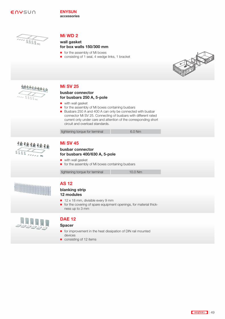
Mi WD 2
wall gasket
for box walls 150/300 mm
for the assembly of Mi boxes consisting of 1 seal, 4 wedge links, 1 bracket
Mi SV 25
busbar connector
for busbars 250 A, 5-pole
with wall gasket for the assembly of Mi boxes containing busbars Busbars 250 A and 400 A can only be connected with busbar
connector Mi SV 25. Connecting of busbars with different rated
current only under care and attention of the corresponding short
circuit and overload standards.
tightening torque for terminal 6.0 Nm
Mi SV 45
busbar connector
for busbars 400/630 A, 5-pole
with wall gasket for the assembly of Mi boxes containing busbars
tightening torque for terminal 10.0 Nm
AS 12
blanking strip
12 modules
12 x 18 mm, divisible every 9 mm for the covering of spare equipment openings, for material thick-
ness up to 3 mm
DAE 12
Spacer
for improvement in the heat dissipation of DIN rail mounted
devices consisting of 12 items

50 | www.hensel-electric.de/en
ENYSUN Accessories
Cable entry
Mi FM 25
Flange
knockouts: 19 x M 16/25
box wall 300 mm with fixing wedges and seal
25300
Mi FM 32
Flange
knockouts: 8 x M 25/32, 1 x M 25/32/40
box wall 300 mm with fixing wedges and seal
25300
Mi FM 40
Flange
knockouts: 2 x M 25/32, 5 x M 32/40
box wall 300 mm with fixing wedges and seal
25300
Mi FM 50
Flange
knockouts: 2 x M 20, 4 x M 32/40/50
box wall 300 mm with fixing wedges and seal
25300
Mi FM 60
Flange
knockouts: 3 x M 40/50/63
box wall 300 mm with fixing wedges and seal
25300
Mi FP 70
flange
sealing range: 1 x Ø 30-72 mm
box wall 300 mm with fixing wedges and seal
300
25
100
Mi FP 72
flange
sealing range: 2 x each Ø 30-72 mm
box wall 300 mm with fixing wedges and seal
300116
25
100

| 51
ENYSUN Accessories
Cable entry
Mi FM 63
flange with cable arrangement space
knockouts: 3 x M 40/50/63
box wall 300 mm with fixing wedges and seal 80
300
Mi FP 82
Cable insert
sealing range: 2 x each Ø 30-72 mm
box wall 300 mm divisible for cable insertion from the front degree of protection IP 54 only with additional strain and pressure
relief (e.g. Mi ZE 62)
300100
45
135
Mi ZE 62
Cable strain relief
for 2 cables with max. 60 mm external diameter
with fixing rail 284 mm long to be used only in connection with cable insertion Mi FP 82

52 | www.hensel-electric.de/en
ENYSUN Accessories
Cable entry
AKM 12
Cable glands for knockouts M 12
sealing range: Ø 4-6 mm ISO thread M 12 x 1.5 bore-hole:Ø 12.3 mm wall thickness up to 3 mm with strain relief and locknut for indoor (normal environment and/or protected outdoor) and
outdoor installation (harsh environment and/or outdoor) ambient temperature - 25 °C to + 55 °C glow wire test IEC 60695-2-11: 960 °C colour: grey, RAL 7035
tightening torque 0,9 Nm
AKM 16
Cable glands for knockouts M 16
sealing range: Ø 5-10 mm ISO thread M 16 x 1.5 bore-hole: Ø 16.3 mm wall thickness up to 3 mm with strain relief and locknut for indoor (normal environment and/or protected outdoor) and
outdoor installation (harsh environment and/or outdoor) ambient temperature - 25 °C to + 55 °C glow wire test IEC 60695-2-11: 960 °C colour: grey, RAL 7035
tightening torque 3,0 Nm
AKM 20
Cable glands for knockouts M 20
sealing range Ø 6,5-13,5 mm ISO thread M 20 x 1.5 bore-hole: Ø 20.3 mm wall thickness up to 3 mm with strain relief and locknut for indoor (normal environment and/or protected outdoor) and
outdoor installation (harsh environment and/or outdoor) ambient temperature - 25 °C to + 55 °C glow wire test IEC 60695-2-11: 960 °C colour: grey, RAL 7035
tightening torque 4,0 Nm
AKM 25
Cable glands for knockouts M 25
sealing range Ø 11-17 mm ISO thread M 25 x 1.5 bore-hole: Ø 25.3 mm wall thickness up to 3 mm with strain relief and locknut for indoor (normal environment and/or protected outdoor) and
outdoor installation (harsh environment and/or outdoor) ambient temperature - 25 °C to + 55 °C glow wire test IEC 60695-2-11: 960 °C colour: grey, RAL 7035
tightening torque 7,5 Nm
| 53
ENYSUN Accessories
Cable entry
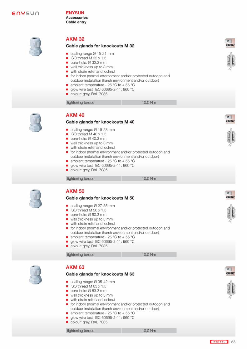
AKM 32
Cable glands for knockouts M 32
sealing range Ø 15-21 mm ISO thread M 32 x 1.5 bore-hole: Ø 32.3 mm wall thickness up to 3 mm with strain relief and locknut for indoor (normal environment and/or protected outdoor) and
outdoor installation (harsh environment and/or outdoor) ambient temperature - 25 °C to + 55 °C glow wire test IEC 60695-2-11: 960 °C colour: grey, RAL 7035
tightening torque 10,0 Nm
AKM 40
Cable glands for knockouts M 40
sealing range: Ø 19-28 mm ISO thread M 40 x 1.5 bore-hole: Ø 40.3 mm wall thickness up to 3 mm with strain relief and locknut for indoor (normal environment and/or protected outdoor) and
outdoor installation (harsh environment and/or outdoor) ambient temperature - 25 °C to + 55 °C glow wire test IEC 60695-2-11: 960 °C colour: grey, RAL 7035
tightening torque 10,0 Nm
AKM 50
Cable glands for knockouts M 50
sealing range: Ø 27-35 mm ISO thread M 50 x 1.5 bore-hole: Ø 50.3 mm wall thickness up to 3 mm with strain relief and locknut for indoor (normal environment and/or protected outdoor) and
outdoor installation (harsh environment and/or outdoor) ambient temperature - 25 °C to + 55 °C glow wire test IEC 60695-2-11: 960 °C colour: grey, RAL 7035
tightening torque 10,0 Nm
AKM 63
Cable glands for knockouts M 63
sealing range: Ø 35-42 mm ISO thread M 63 x 1.5 bore-hole: Ø 63.3 mm wall thickness up to 3 mm with strain relief and locknut for indoor (normal environment and/or protected outdoor) and
outdoor installation (harsh environment and/or outdoor) ambient temperature - 25 °C to + 55 °C glow wire test IEC 60695-2-11: 960 °C colour: grey, RAL 7035
tightening torque 10,0 Nm

54 | www.hensel-electric.de/en
ENYSUN Accessories
Outdoor applications
Mi BF 44
Ventilation flange
for vertical installation on box walls
box wall 300 mm for ventilation of Mi-Distribution boards in the event of extremely
high internal temperatures or a risk of water condensation
BE 44
Ventilation insert

| 55
ENYSUN Accessories
Outdoor applications
BM 20G
Pressure compensation element for M 20 knockouts
for the reduction of condensation by pressure compensation in
power distribution systems ISO thread M 20 x 1.5 bore-hole: Ø 20.3 mm wall thickness up to 4 mm with counter nut for indoor (normal environment and/or protected outdoor) and
outdoor installation (harsh environment and/or outdoor) ambient temperature - 25 °C to + 55 °C In order not to exceed leakage limit of 0.07 bar with pressure
compensation, one pressure compensation element BM 20G
must be used per 28 litres (28000 cm³) of enclosure volume. Example: enclosure size 30 cm x 60 cm x 17 cm = 30600 cm³ =
30,6 litres. Number of necessary BM 20G (M32) = 2 piece. technical changes reserved colour: grey, RAL 7035
31
13
22
M20x1,5
BM 40G
Pressure compensation element for M 40 knockouts
for the reduction of condensation by pressure compensation in
power distribution systems ISO thread M 40 x 1.5 bore-hole: Ø 40.3 mm wall thickness of up to 8 mm with counter nut for indoor (normal environment and/or protected outdoor) and
outdoor installation (harsh environment and/or outdoor) ambient temperature - 25 °C to + 55 °C In order not to exceed leakage limit of 0.07 bar with pressure
compensation, one pressure compensation element BM 40G
must be used per 122 litres (122000 cm³) of enclosure volume. Example: enclosure size 60 cm x 60 cm x 17 cm = 61200 cm³ =
61,2 litres. Number of necessary BM 40G (M40) = 1 piece. technical changes reserved colour: grey, RAL 7035
56
19
35
M40x1,5
Pressure compensation element
poutside = pinside

56 | www.hensel-electric.de/en
Mi DB 15
Canopy
for box wall 150 mm
with fixing wedges and seal suitable for outdoor installation, UV resistant
material stainless steel
powder-coated
ENYSUN Accessories
Outdoor applications
Mi DB 30
Canopy
for 300 mm box walls
with fixing wedges and seal suitable for outdoor installation, UV resistant
material stainless steel
powder-coated
Mi DB 01
canopy end plate
for canopies FP DB xx and Mi DB xx
material stainless steel
powder-coated
Canopy
| 57
ENYSUN Accessories
Locking facilities
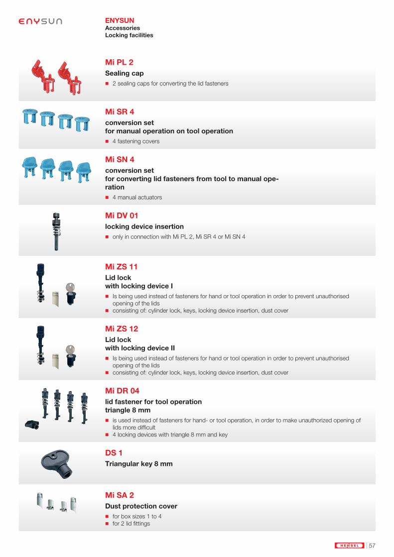
Mi PL 2
Sealing cap
2 sealing caps for converting the lid fasteners
Mi SR 4
conversion set
for manual operation on tool operation
4 fastening covers
Mi SN 4
conversion set
for converting lid fasteners from tool to manual ope-
ration
4 manual actuators
Mi DV 01
locking device insertion
only in connection with Mi PL 2, Mi SR 4 or Mi SN 4
Mi ZS 11
Lid lock
with locking device I
Is being used instead of fasteners for hand or tool operation in order to prevent unauthorised
opening of the lids consisting of: cylinder lock, keys, locking device insertion, dust cover
Mi ZS 12
Lid lock
with locking device II
Is being used instead of fasteners for hand or tool operation in order to prevent unauthorised
opening of the lids consisting of: cylinder lock, keys, locking device insertion, dust cover
Mi DR 04
lid fastener for tool operation
triangle 8 mm
is used instead of fasteners for hand- or tool operation, in order to make unauthorized opening of
lids more difficult 4 locking devices with triangle 8 mm and key
DS 1
Triangular key 8 mm
Mi SA 2
Dust protection cover
for box sizes 1 to 4 for 2 lid fittings

58 | www.hensel-electric.de/en
ENYSUN Accessories
Wall mounting
Mi AL 40
4 stainless steel external brackets
for external fixing of enclosures
20
30
15
Mi MS 2
Profile for wall mounting
for Mi distribution board assemblies up to 900 x 1200 mm with 8 screws M6 x 16, washers and nuts for mounting enclo-
sures
length 1950 mm
material sendzimir galvanised steel profile
with structured powder coating

| 59
Technical Data
ENYSUN

60 | www.hensel-electric.de/en
ENYSUNTechnical Data
Material Properties
Glo
w w
ire
te
st
IE
C 6
06
95
-2-1
1
Chemical resistance 1)
Products Material used
UL
Su
bje
ct
94
Te
mp
era
ture
resis
tan
ce
Ac
id 1
0 %
Lye
10
%
Alc
oh
ol
Pe
tro
l (M
AK
) 2
)
Be
nze
ne
(M
AK
) 2
)
Min
era
r o
il
bases of Mi ... PC
(polycabonate)
(with GFS)
960 °C V-0 -40 °C /
+120 °C
+ + 0 + — +
lid Mi ...
door and lid KV ... /
PC
(polycabonate)
960 °C V-0 -40 °C /
+120 °C
+ + 0 + — +
Sealings
KV ... / Mi FP ...
TPE
(thermoplastic
elastomer)
750 °C — -25 °C /
+100 °C
+ + + 0 0 0
Sealings
KV ...
Mi ...
PUR
(polyurethane)
— — -25 °C /
+80 °C
0 + 0 0 — +
AKM ..
BM ...
PA (polyamide) 960 °C V-0 -40 °C /
+100 °C
+ 0 + + + +
Sealings
AKM ..
CR/NBR
(polychloroprene
- nitrile rubber)
— — -20 °C /
+100 °C
+ + + 0 — 0
As at: June 2016
( + = resistance; 0 = partially resistance; — = not resistant)
1) The specifi cations on chemical resistance are a general guide. In individual cases it may be necessary to check resistance in combination
with other chemicals and ambient conditions (temperature. concentration. etc.)
2) (MAK) - Maximum allowable concentration (work place)
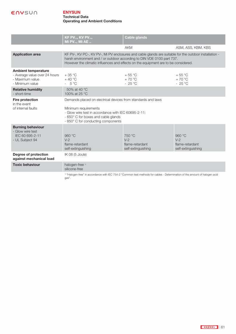
| 61
ENYSUNTechnical Data
Operating and Ambient Conditions
KF PV.., KV PV..,
Mi PV.., Mi AE ..
Cable glands
AKM ASM, ASS, KBM, KBS
Application area KF PV-, KV PC-, KV PV-, Mi PV enclosures and cable glands are suitable for the outdoor installation -
harsh environment and / or outdoor according to DIN VDE 0100 part 737.
However the climatic infl uences and effects on the equipment are to be considered.
Ambient temperature
- Average value over 24 hours
- Maximum value
- Minimum value
+ 35 °C
+ 40 °C
- 5 °C
+ 55 °C
+ 70 °C
- 25 °C
+ 55 °C
+ 70 °C
- 25 °C
Relative humidity
- short-time
50% at 40 °C
100% at 25 °C
Fire protection
in the event
of internal faults
Demands placed on electrical devices from standards and laws
Minimum requirements
- Glow wire test in accordance with IEC 60695-2-11:
- 650° C for boxes and cable glands
- 850° C for conducting components
Burning behaviour
- Glow wire test
IEC 60 695-2-11
- UL Subject 94
960 °C
V-2
fl ame-retardant
self-extinguishing
750 °C
V-2
fl ame-retardant
self-extinguishing
960 °C
V-2
fl ame-retardant
self-extinguishing
Degree of protection
against mechanical load
IK 08 (5 Joule)
Toxic behaviour halogen-free 1)
silicone-free
1) “Halogen-free” in accordance with IEC 754-2 “Common test methods for cables - Determination of the amount of halogen acid
gas”.

62 | www.hensel-electric.de/en
ENYSUNTechnical Data
Standards and Requirements
Distribution boards assembled and wired according to manufacturer data without essential deviations
from the original type or system.
To meet these requirements for Hensel Mi Distribution Boards, the following must be noted:
1. The distribution boards must consist of the verifi ed enclosures documented in this list.
2. The wiring of the equipment must be carried out with the cross-sections and con-
ductor types indicated in Table “Rating of insulated conductors in switchgear assemblies”, Index Tech-
nics.
3. Once the distribution board is completed, a routine test must be carried out in accordance with this
standard.
4. The test must be certifi ed with a test report.
5. The assembly must be provided with a manufacturer’s identifi cation mark.
Compliance with important data such as
- limit of temperature rise
- dielectric strength
- IP degrees of protection
- creepage distances and clearances
is verifi ed for this system.
- IEC 61439-1
Low voltage switchgear and controlgear assemblies
- IEC 60999
Safety requirements for screw-type and screwless-type clamping units for electrical copper conductors
- DIN EN 50262
Metric threaded cable glands for electrical installations
- IEC 60269
Low voltage fuses
- DIN 43880
Built-in equipment for electrical installations;
overall dimensions and related mounting dimensions
- IEC 60529
Degrees of protection provided by enclosures (IP-Code)
- IEC 60364-7-712
Electrical installations of buildings
Requirements for special installations or locations –
Solar photovoltaic (PV) power supply systems
Generator junction boxes
and solar inverter collector
comply with the require-
ments of the IEC 61439 part
1 and part 2
Standards and regulations

| 63
ENYSUN
Technical Data
Outside Diameter of Conventional Cable Cross Sections
Short Forms of Cables
The outside diameters are
average values of different
products.
Cable
cross-
section
mm²
NYM
mm Ø
NYY
mm Ø
NYCY
NYCWY
mm Ø
1x4 8 9 —
1x6 8.5 10 —
1x10 9.5 10.5 —
1x16 11 12 —
1x25 — 14 —
1x35 — 15 —
1x50 — 16.5 —
1x70 — 18 —
1x95 — 20 —
1x120 — 21 —
1x150 — 23 —
1x185 — 25 —
1x240 — 28 —
1x300 — 30 —
2x1.5 10 12 —
2x2.5 11 13 —
2x4 — 15 —
2x6 — 16 —
2x10 — 18 —
2x16 — 20 —
2x25 — — —
2x35 — — —
3x1.5 10.5 12.5 13
3x2.5 11 13 14
3x4 13 16 16
3x6 15 17 17
3x10 18 19 18
3x16 20 21 21
3x25 — 26 —
3x35 — — —
3x50 — — —
3x70 — — —
3x95 — — —
3x120 — — —
3x150 — — —
3x185 — — —
3x240 — — —
3x25/16 — 27 27
3x35/16 — 28 27
3x50/25 — 32 32
3x70/35 — 32-36 36
3x95/50 — 37-41 40
3x120/70 — 42 43
3x150/70 — 46 47
3x185/95 — 52 48-54
3x240/120 — 57-63 60
3x300/150 — 63-69 —
Cable
cross-
section
mm²
NYM
mm Ø
NYY
mm Ø
NYCY
NYCWY
mm Ø
4x1.5 11 13.5 14
4x2.5 12.5 14.5 15
4x4 14.5 17.5 17
4x6 16.5 18 18
4x10 18.5 20 20
4x16 23.5 23 23
4x25 28.5 28 28
4x35 32 26-30 29
4x50 — 30-35 34
4x70 — 34-40 37
4x95 — 38-45 42
4x120 — 42-50 47
4x150 — 46-53 52
4x185 — 53-60 60
4x240 — 59-71 70
4x25/16 — — 30
4x35/16 — — 30
4x50/25 — — 34-37
4x70/35 — — 40
4x95/50 — — 44.5
4x120/70 — — 48.5
4x150/70 — — 53
4x185/95 — — —
4x240/120 — — —
5x1.5 12 15 15
5x2.5 13.5 16 17
5x4 15.5 16.5 18
5x6 18 19 20
5x10 20 21 —
5x16 26 24 —
5x25 31.5 — —
7x1.5 13 16 —
7x2.5 14.5 16.5 —
19x1.5 — 22 —
24x1.5 — 25 —
Short forms of cables
NYM Light plastic-sheathed cable
NYY Plastic-sheathed cable
NYCY Plastic-sheathed cable with concentric
conductor
NYCWY Plastic-sheathed cable with concentric.
undulated conductor

64 | www.hensel-electric.de/en
ENYSUN
Technical Data
Assignment of Cable Outside Diameters to Cable Entries
Standards and Requirements
Hensel cable entries
comply with the following
standards and regulations:
- EN 50262
Metric cable entries for electrical installations
- EN 60423
Conduits for electrical purposes - Outside diameter of conduits for
electrical installations and threads for conduits and fi ttings
- IEC 60529
Degrees of protection provided by enclosures (IP-Code)
Outside diameter of cables Cable entry
metricmin. mm Ø max. mm Ø
4.8 11 ESM 16
6 13 ESM 20
9 17 ESM 25
9 23 ESM 32
17 30 ESM 40
Outside diameter of cables Cable entry
metricmin. mm Ø max. mm Ø
3 6.5 AKM/ASS 12
5 10 AKM/ASS 16
6.5 13.5 AKM/ASS 20
10 17 AKM/ASS 25
14 21 AKM/ASS 32
20 28 AKM/ASS 40
25 35 AKM/ASS 50
35 48 AKM/ASS 63
5 10 AFM 16
8 13 AFM 20
11 17 AFM 25
15 21 AFM 32
Outside diameter of cables Cable entry
metricmin. mm Ø max. mm Ø
Conduit
M 16 EDR 16
M 20 EDR 20
M 25 EDR 25
M 32 EDR 32
M 40 EDR 40
Outside diameter of cables Cable entry
metric
min. mm Ø max. mm Ø
3.5 12 STM 16
5 16 STM 20
5 21 STM 25
13 26.5 STM 32
13 34 STM 40
Grommets ESM
Degree of protection: IP 55
Grommets are inserted into
knockouts.
No nut is necessary!
Cable glands AKM/ASS
Degree of protection: up to IP 67
With strain relief and counternut.
Grommets for conduits EDR
Degree of protection: IP 65
Grommets for concuits are
inserted into knock outs.
No nut is necessary!
Stepped grommets STM
Degree of protection: IP 55
Stepped grommets are
inserted into knock outs.
No nut is necessary!
Grommets EDK
Degree of protection: IP 65
Grommets are inserted into
knock outs.
No nut is necessary!
Outside diameter of cables Cable entry
metricmin. mm Ø max. mm Ø
5 10 EDK 16
6 13 EDK 20
9 17 EDK 25
8 23 EDK 32
11 30 EDK 40

| 65
ENYSUNTechnical Data
Defi nition of terms
Defi nition of Terms
Rated values for setting up
low-voltage switchgear are
given in the standard
IEC 61439-1
Rated voltage (Un)
highest nominal value of the a.c. (r.m.s.) or d.c.
voltage, declared by the assembly manufacturer,
to which the main circuit(s) of the assembly is (are)
designed to be connected.
Rated operational voltage (Ue) (of a circuit of
an assembly)
value of voltage, declared by the assembly ma-
nufacturer, which combined with the rated current
determines its application.
Rated insulation voltage (Ui)
r.m.s. withstand voltage value, assigned by the
assembly manufacturer to the equipment or to a
part of it, characterising the specifi ed (long-term)
withstand capability of the insulation.
Rated impulse voltage (Uimp)
impulse withstand voltage value, declared by the
assembly manufacturer, characterising the speci-
fi ed withstand capability of the insulation against
transient overvoltages.
Rated current (In)
value of current, declared by the assembly manu-
facturer taking into consideration the ratings of
the components, their disposition and application,
which can be carried without the temperature-rise
of various parts of the assembly exceeding speci-
fi ed limits under specifi ed conditions.
Prospective short circuit current (Icp)
current which fl ows when the supply conductors
to the circuit are short-circuited by a conductor of
negligible impedance located as near as practica-
ble to the supply terminals of the assembly.
Rated peak withstand current (Ipk)
value of peak short-circuit current, declared by
the assembly manufacturer, that can be withstood
under specifi ed conditions.
Rated short-time withstand current (Icw)
r.m.s value of short-time current, declared by the
assembly manufacturer, that can be carried without
damage under specifi ed conditions, defi ned in
terms of a current and time.
Rated current of the assembly (InA)
The rated current of the assembly is the smaller of:
- the sum of the rated currents of the incoming
circuits within the assembly operated in parallel;
- the total current which the main busbar is ca-
pable of distributing in the particular assembly
arrangement.
This current shall be carried without the tempera-
ture rise of the individual parts exceeding the limits
specifi ed in the standard.
Rated current of a circuit (Inc)
The rated current of a circuit is stated by the as-
sembly manufacturer, taking into consideration the
ratings of the devices within the circuit, their dispo-
sition and application. This current shall be carried
without the temperature rise of the various parts of
the assembly exceeding the limits specifi ed in the
standard when the circuit is loaded alone.
Rated diversity factor (RDF)
per unit value of the rated current, assigned by the
assembly manufacturer, to which outgoing circuits
of an assembly can be continuously and simul-
taneously loaded taking into account the mutual
thermal infl uences.

66 | www.hensel-electric.de/en
ENYSUNCheck List for PV Generator Junction Boxes
Request/offer Order Date:
DC
AC
Checklist provided as an editable PDF fi le on the Internet at www.enysun.eu
Quantity of PV generator junction boxes (pieces): _______________
Installation und ambient conditions
Ambient temperature (°C): _______________
Installation
- Indoor installation: in closed electrical operating room in factory
- Outdoor installation: protected outdoor unprotected outdoor
Available wall surface in mm: Width: ______________ Height: ______________ Depth: ______________
Assembly type: wall-mounted fl oor-standing
Degree of protection: IP 44 IP 54 IP 55 IP 65 IP _______________
Connection inverter
Rated voltage (UOC STC): ___________ V d.c.
Solar inverter feeding 1 2 3 _________
(MPP tracker)
DC generator disconnect yes no
switch:
Connection of conductors Multi Contact MC4 _______________
going to inverter: Screw connection and terminals
Cable cross-section (mm²): _________________
Overvoltage protection: no yes Type 1 Type 2 Floating remote indication
Manufacturer: Dehn _______________
Earthing cable type NYY 1 x 16 mm² _______________
and diameter:
Cable entry: Cable glands
Anschluss Stränge
Number of strings
per box: 1 2 3 4 _____
Current per string: 15 A 30 A _______________
String overload protection: yes no
Blocking diodes: yes no
Connection of conductors: Multi Contact MC4 _______________
Screw connection and terminals
Cable cross-section (mm²): _________________
Contractor:
Name:
Address:
Tel.:
E-Mail:
Project:
Gustav Hensel GmbH & Co. KG ∙ Elektroinstallations- und Ver tei lungs sy ste me ∙ 57368 Lennestadt ∙ www.hensel-electric.de
• protection class II �• ready for connection
• with external stainless steel bracket
• lid fasteners for tool operation
• material: thermoplastic
• colour: grey, RAL 7035
• degree of protection: IP 65

| 67
Request/offer Order Date:
ENYSUNCheck List for Solar Inverter Collectors
DC
AC
Checklist provided as an editable PDF fi le on the Internet at www.enysun.eu
Quantity of Solar inverter collectors (pieces): _______________
Installation und ambient conditions
Ambient temperature (°C): _______________
Installation
- Indoor installation: in closed electrical operating room in factory
- Outdoor installation: protected outdoor unprotected outdoor
Available wall surface in mm: Width: ___________ Height: ___________ Depth: __________
Assembly type: wall-mounted fl oor-standing
Degree of protection: IP 44 IP 54 IP 55 IP 65 IP ________
Connection to the public power supply system
Rated voltage: ________ V a.c. ________ Hz Rated current: _________ A
Conductor designation: L1, L2, L3 N PE PEN
Protection class: I II
Incoming device: HRC fuse switch disconnector switch disconnector ___________________________________
Connection incoming:
from top from below from left from right _______________
copper aluminium
with cable lug with terminal
conductor single conductor cross-section (mm²): _______________
Circuits and consumer
Solar inverter connection:
from top from below from left from right _______________
connected to device via terminal blocks cross-section (mm²): _________________
Inverter (manufacturer/type): ___________________________________
Quantity (pieces): ___________
Output (kVA): ___________
Current (A): ___________
Solar inverter connection (1~/3~): / / / /
RCD (residual current protective): no yes Type A Type B
Wire protection to solar inverter: MCB fuse element fuse switch disconnector
Overvoltage protection: yes Type 1 Type 2 fl oating remote indication
Notes:
____________________________________________________________________________________________________________________
____________________________________________________________________________________________________________________
Gustav Hensel GmbH & Co. KG ∙ Elektroinstallations- und Ver tei lungs sy ste me ∙ 57368 Lennestadt ∙ www.hensel-electric.de
Contractor:
Name:
Address:
Tel.:
E-Mail:
Project:
• protection class II �• ready for connection
• material: thermoplastic
• colour: grey, RAL 7035

68 | www.hensel-electric.de/en
Erklärung der EG-Konformität
Declaration of EC Conformity
Nr./No. K-2016-8
Das Produkt / Typ ENYSUN, Typen MI PV...., Mi AE..., KV PV....
The product / Type ENYSUN, types MI PV...., Mi AE..., KV PV....
Hersteller
Manufacturer Gustav Hensel GmbH & Co. KG
Gustav-Hensel-Straße 6
57368 Lennestadt
Beschreibung Generatoranschlusskästen, Wechselrichtersammler und
Freischaltstellen für Erzeugungsanlagen
Description Generator junction boxes, solar inverter collectors and
switching devices for generation plants
auf das sich diese Erklärung bezieht, stimmt mit folgenden Normen oder normativen
Dokumenten überein:
to which this declaration relates is in conformity with the following standard(s) or normative document(s):
Norm
Standard DIN EN 61439-2
EN 61439-2
IEC 61439-2
und entspricht den Bestimmungen der folgenden EG-Richtlinie(n):
and is in accordance with the provisions of the following EC-directive(s)
Niederspannungs-Richtlinie 2014/35/EG
Low voltage directive 2014/35/EU
EMV Richtlinie 2014/30/EG
EMV directive 2014/30/EU
RoHS Richtlinie 2011/65/EG
RoHS directive 2011/65/EU
Diese Konformitätserklärung entspricht der Europäischen Norm EN 17050-1 „Allgemeine Anforderungen für Konformitätserklärungen von
Anbietern“. Diese Erklärung gilt weltweit als Erklärung des Herstellers zur Übereinstimmung mit den oben genannten internationalen und
nationalen Normen.
This Declaration of Conformity is suitable to the European Standard EN 17050-1 „General requirements for supplier‘s declaration of con-
formity“. The declaration is world-wide valid as the manufacturer’s declaration of compliance with the requirements of the a.m. national and
international standards.
Jahr der Anbringung der
CE-Kennzeichnung 2012
Year of affixing CE-Marking
Ausstellungsdatum 22.04.2016
Date of issue
Gustav Hensel GmbH & Co. KG
O. Gutzeit
- Technische Geschäftsleitung -
- Technical Managing Director -

| 69
Notes
70 | www.hensel-electric.de/en
Notes

Africa
Angola
Egypt
Kenya
Mozambique
South Africa
America
USA
Asia
Bangladesh
Bhutan
Cambodia
China
India
Indonesia
Japan
Kazakhstan
Malaysia
Maldives
Myanmar
Nepal
Pakistan
Philippines
Singapore
Sri Lanka
Taiwan
Thailand
Vietnam
Europe
Albania
Austria
Belgium
Bosnia-Herze-
govina
Bulgaria
Croatia
Czech Republic
Denmark
Estonia
Finland
France
Great Britain
Hungary
Iceland
Ireland
Israel
Italy
Kazakhstan
Kosovo
Latvia
Lithuania
Luxembourg
Macedonia
Moldovia
Montenegro
Netherlands
Norway
Poland
Portugal
Romania
Russia
Serbia
Slovakia
Slovenia
Spain
Sweden
Switzerland
Turkey
Ukraine
Middle East
United Arab
Emirates
Bahrain
Iran
Kuwait
Oman
Qatar
Saudi Arabia
Oceania
Australia
New Zealand
Representations abroadSubsidiaries abroad
Czech Republic
Hensel s.r.o.
www.hensel.cz
Hungary
Hensel Hungaria Villamossági Kft.
www.hensel.hu
Poland
Hensel Polska Sp. z o. o.
www.hensel-electric.pl
Russia
OOO Hensel + Mennekes Elektro
www.hensel-electric.ru
India
Hensel Electric India Pvt. Ltd
www.hensel.in
Turkey
Hensel Electric Turkey Ltd.
www.hensel-electric.com.tr
People's Republic of China
Hensel (Qingdao)
Electrical Installation and
Distribution Systems Co. Ltd
www.hensel-electric.cn
The Company
Since 1931 HENSEL has been developing and manufacturing innovative solutions for electrical equipment
in buildings. Electrical installation and distribution systems made of high quality thermoplastic are used
today because of their special properties in areas where dust and humidity place high demands on the
electrical installation.
Highest quality for the highest requirements
Headquaters in Germany

Gustav Hensel GmbH & Co. KGElektroinstallations- und Ver tei lungs sy ste me
Altenhundem
Gustav-Hensel-Straße 6
D-57368 Lennestadt, Germany
P.O. Box 1461
D-57344 Lennestadt, Germany
Phone: +49 (0)2723/609-0
Fax: +49 (0)2723/60052
E-Mail: [email protected]
www.hensel-electric.de
98 17 0684 06.16/2/19