catalogue els/sv - lisol scandinavia abmedia2.lisol.se/2016/11/cat-els.pdf · catalogue els/sv...
TRANSCRIPT

Emergency lighting system withindividual lamp monitoring
Type ELS-SV
CatalogueELS/SV
Sicherheitstechnik GmbH
FailureOperation
Batt.-Operation
Remote ControlLight Switch
Indicator
output
Operation
Batt.-Operation
Failure
Charging failure
Menue
Enter
Change
Test
FS 24V RTG B SLCH1 CH2 CH3 CH4
230V / AC50 / 60 Hz 4
N L PE
3N L PEL N L NL NL N
3,15 AT3,15 AT3,15 AT3,15 AT3,15 AT
1 654322
N L PE
1N L PEPE LN
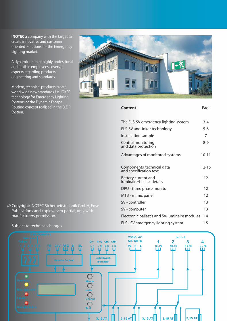
INOTEC a company with the target to create innovative and customer oriented solutions for the Emergency Lighting market.
A dynamic team of highly professional and flexible employees covers all aspects regarding products, engineering and standards.
Modern, technical products create world wide new standards, i.e. JOKER technology for Emergency Lighting Systems or the Dynamic Escape Routing concept realised in the D.E.R. System.
Content Page
The ELS-SV emergency lighting system 3-4
ELS-SV and Joker technology 5-6
Installation sample 7
Central monitoring 8-9and data protection
Advantages of monitored systems 10-11
Components, technical data 12-15and specification text
Battery current and 12luminaire/ballast details
DPÜ - three phase monitor 12
MTB - mimic panel 12
SV - controller 13
SV - computer 13
Electronic ballast's and SV-luminaire modules 14
ELS - SV emergency lighting system 15
Copyright: INOTEC Sicherheitstechnik GmbH, EnsePublications and copies, even partial, only with maufacturers permission.
Subject to technical changes
Features
Supply and automatic function monitoring of upto 60 safety- and exit luminaries Operation of switched maintained-, maintained- and non-maintained- luminaries on one circuit
Display of faulty luminaries with location (optional)
Automatic function- and battery duration test of emergency lighting system with battery-circuit, internal circuits and every connected luminaire
Display of failures, status information during normal operation and test conditions
Selectable 1h or 3h operation time
Compact and flexible
Ideal for use within one fire-zone only
No data line required
Mix and match all possible switching modes on one circuit
Easy to install
Central battery replacement instead of time consuming changes on self-contained luminaries.
Centralised automatic failure info allows spot-on service
Automatic function- and battery duration tests
Connection possibilities to building managment systems or in-house central monitors
High performance and safety-level due to decentralised installation
Compact assembly, depth just 110mm
Attractive, elegant housing withclear perspec door
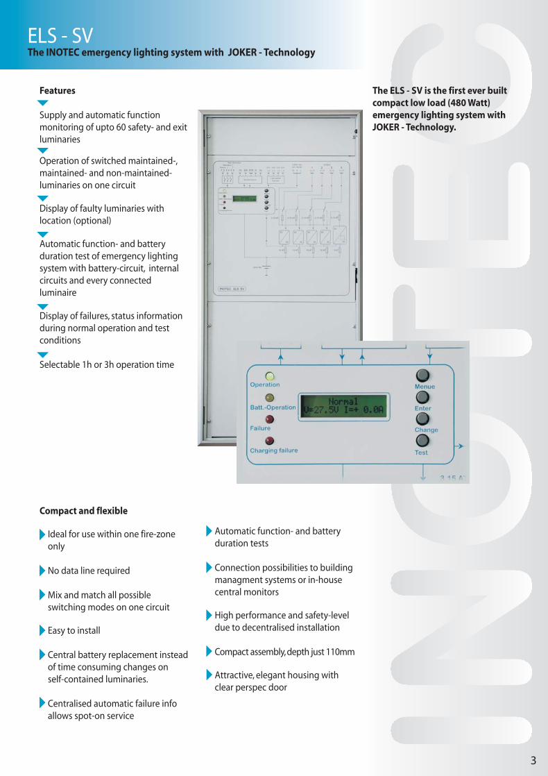
The ELS - SV is the first ever built compact low load (480 Watt) emergency lighting system with JOKER - Technology.
ELS - SVThe INOTEC emergency lighting system with JOKER - Technology
3

FailureOperation
Batt.-Operation
Remote ControlLight Switch
Indicator
output
Operation
Batt.-Operation
Failure
Charging failure
Menue
Enter
Change
Test
FS 24V RTG B SLCH1 CH2 CH3 CH4
230V / AC50 / 60 Hz 4
N L PE
3N L PEL N L NL NL N
3,15 AT3,15 AT3,15 AT3,15 AT3,15 AT
1 654322
N L PE
1N L PEPE LN
Every INOTEC emergency lighting system contains components guaranteeing, together with the connected luminaries, a maximum on function and safety.
ELS - SVControl module, charger and change-over devices
The four push-buttons next to the display allow the programming of the system, the manual release of tests and the status- and failure interrogation for the individual system. The pre-set tests (function-test usually every 7 days, battery duration test usually every 12 month) are free programmable. The display text is adapted to the native language.
The constant current charger 3 Amps is monitored via the control module.The battery recharging time is < 10 h.
Every one of the 4 change-over devices supplies up to 15 INOTEC safety- or exit luminaries. During mains supply 230V, 50/60Hz are present on the output; in emergency or test mode this supply comes from the battery pack.
4
LED display the following mandatory status info:
Operation (mains supply healthy)
Battery operation (test or mains failure)
Failure (luminaire-, system- or mains failure)
Charging failure
The free programmable control module with two-line liquid crystal display for plain text information has three main tasks:
Monitor and control all internal functions and test-cycles, allow manual interaction
Display all panel and luminaire information(failure and status info)
Safe all information concerning tests, status of luminaries and panel for log-book purpose
The display shows:
Battery voltage
Battery charging current
Battery discharge current during test or emergency operation
Charging failures- battery voltage to high / low- interrupted charge circuit- required duration test time not achieved
Luminaire failure
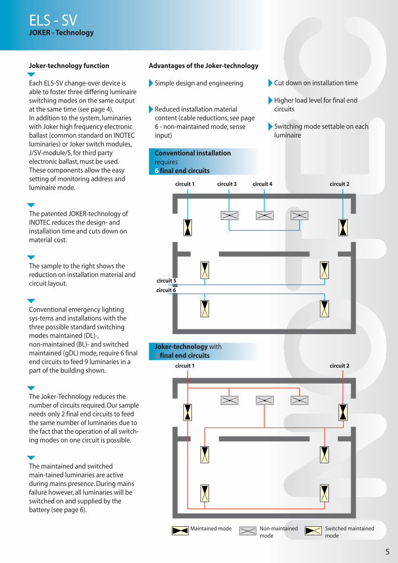
Joker-technology function
Each ELS-SV change-over device is able to foster three differing luminaire switching modes on the same output at the same time (see page 4).In addition to the system, luminaries with Joker high frequency electronic ballast (common standard on INOTEC luminaries) or Joker switch modules, J/SV-module/S, for third party electronic ballast, must be used. These components allow the easy setting of monitoring address and luminaire mode.
The patented JOKER-technology of INOTEC reduces the design- and installation time and cuts down on material cost.
The sample to the right shows the reduction on installation material and circuit layout.
Conventional emergency lighting sys-tems and installations with the three possible standard switching modes maintained (DL)-, non-maintained (BL)- and switched maintained (gDL) mode, require 6 final end circuits to feed 9 luminaries in a part of the building shown.
The Joker-Technology reduces the number of circuits required. Our sample needs only 2 final end circuits to feed the same number of luminaries due to the fact that the operation of all switch-ing modes on one circuit is possible.
The maintained and switched main-tained luminaries are active during mains presence. During mains failure however, all luminaries will be switched on and supplied by the battery (see page 6).
Advantages of the Joker-technology
Simple design and engineering
Reduced installation material content (cable reductions, see page 6 - non-maintained mode, sense input)
Cut down on installation time
Higher load level for final end circuits
Switching mode settable on each luminaire
ELS - SVJOKER - Technology
5
Maintained mode Non-maintainedmode
Switched maintainedmode
Joker-technology with 2 final end circuits
circuit 1 circuit 2
Conventional installation requires6 final end circuits
circuit 3 circuit 4circuit 1
circuit 5
circuit 6
circuit 2
FailureOperation
Batt.-Operation
Remote ControlLight Switch
Indicator
output
Operation
Batt.-Operation
Failure
Charging failure
Menue
Enter
Change
Test
FS 24V RTG B SLCH1 CH2 CH3 CH4
230V / AC50 / 60 Hz 4
N L PE
3N L PEL N L NL NL N
3,15 AT3,15 AT3,15 AT3,15 AT3,15 AT
1 654322
N L PE
1N L PEPE LN
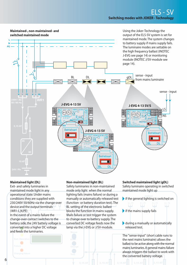
Maintained-, non-maintained- and switched maintained mode
Using the Joker-Technology the output of the ELS-SV system is set for maintained mode. The system changes to battery supply if mains supply fails. The luminaire modes are settable on the high frequency ballast (INOTEC J-EVG see page 14) or monitoring module (INOTEC J/SV-module see page 14).
Non-maintained light (BL)Safety luminaries in non-maintained mode only light when the normal lighting fails (mains failure) or during a manually or automatically released test (function- or battery duration test). The BL-setting of the electronic ballast blocks the function in mains supply.Mails failure or test trigger the system to change over to battery supply. The converted DC voltage feeds now the lamp via the J-EVG or J/SV-module.
Switched maintained light (gDL)Safety luminaire operating in switched maintained mode light up
if the general lighting is switched on
if the mains supply fails
during a manually or automatically released test.
The "sense-input" (short cable runs to the next mains luminaire) allows the ballast to be active along with the normal mains luminaries. A general mains failure always triggers the ballast to work with the converted battery voltage.
Maintained light (DL)Exit- and safety luminaries in maintained mode light in any operational state. Under mains conditions they are supplied with 230/240V 50/60Hz via the change-over device and the output terminals (WR1-L,N,PE)In the event of a mains failure the change-over contact switches to the battery side, the 24V battery voltage is converted into a higher DC voltage and feeds the luminaries.
sense - inputfrom mains luminaire
sense - input
ELS - SVSwitching modes with JOKER - Technology
6
230V / AC50 / 60 Hz
DC
DC
3,15 AT
10 AT
WR1
N PELN PEL
N
PE
L
24V / Pb
LS
NS
BL DL gDL
TL / TC / TCD- EL
N-N-
L+L+
Lampe: 4-13 W
Betriebsart
BL DLGeeignet für Anlagen gem. /acc. to EN 50172
ta:EMC:
INOTEC
J-EVG
In
34
12U :N
λ :
gem./acc to EN 55015
AC 230V 50 / 60HzDC 176 - 264 V
0,95-15 bis 50°C
tctc=70°C max
Temp.-Test
860 0054-13 SV/S
NS
LS
AC 2
30V
Adresse
Zehner Einer
09 8
1
3
45
6
7
2
09 8
1
3
45
6
7
2
J-EVG 4-13 SV/SJ-EVG 4-13 SV
J-EVG 4-13 SV
INOTEC
Adresse
Zehner Einer
09 8
1
3
45
6
7
2
09 8
1
3
45
6
7
2N-N-
L+L+
TL /
TC /
TCD
- EL
Lam
pe: 4
-13
W
Betriebsart
BL DLGeeignet für Anlagen gem. /acc. to EN 50172
ta:EMC:
J-EVG 4-13 SV 12
34
:N
λ :
gem./acc to EN 55015
AC 230V 50 / 60HzDC 176 - 264 V
0,95BL (-15 bis 65°C) DL (-15 bis 50°C)
tctc=70°C max
Temp.-Test
860 004
In
U

RTG-data line
Max. cable run
3 x 0,5mm² 1000m
3 x 1.0mm² 1500m
3 x 1,5mm² 2000m
Remote switch
F+ / F-
Closed:
emergency function possible
Open:
system blocked
Voltfree contacts, max 24V, 3A AC/DC, external supply Mains operation
1 / 2 3 / 4 5 / 6
Mains operation closed closed open
Mains failure open open closed
Charge fault open open open
Luminaire failure open open open
Deep discharge activated closed open open
Function test closed open closed
Duration test closed open closed
7
ELS - SVInstallation sample
Sample with two 3-phase monitors, mimic panel and switched maintained output via light-switch monitor (LA4)
L1L2L3NPEUV/DB1
1
2
3
4
5
13
14
15
1
2
3
4
5
13
14
15
1
2
3
4
5
13
14
15
1
2
3
4
5
13
14
15
NLNLNL N LLA1 LA2 LA3 LA4
SL+
B–
B+
SL–
1 2
failu
re
oper
atio
n
batt.
-op
erat
ion
rem
ote
switc
h24
Vou
tput
3 4 5 6 F+ F– 24V G T RPE N L
mai
ns 2
30V
AC
light
sw
itch
light
sw
itch
light
sw
itch
data
line
N L PE
3,15AT
N L PE
3,15AT
N L PE
3,15AT
N L PE
3,15AT
WR 1ELS/SVTerminal rail
WR 2 WR 3 WR 4
light switch
generallighting
general lighting
3
3
33
Betrieb
Batt.-Betrieb
Störung
Ein
Aus
INOTEC MTB
Fernschalter
Meldetableau Notlicht
mains luminaries
L1L2L3NPE
UV/DB2
U<DPÜ
U<DPÜ

FailureOperation
Batt.-Operation
Remote ControlLight Switch
Indicator
output
Operation
Batt.-Operation
Failure
Charging failure
Menue
Enter
Change
Test
FS 24V RTG B SLCH1 CH2 CH3 CH4
230V / AC50 / 60 Hz 4
N L PE
3N L PEL N L NL NL N
3,15 AT3,15 AT3,15 AT3,15 AT3,15 AT
1 654322
N L PE
1N L PEPE LN
ELS - SVCentral monitoring and data-protection
Information of INOTEC-standard SVPC can be found on page 13.
As an option INOTEC offers the programming of a building plan
including all safety and emergency luminaries. This feature allows easy
localisation of failures and gives, after releasing a print-out, even service personal unfamiliar with the site a
simple and fast orientation possibility.
All stored log-book entries can be selected in various levels, i.e. display only lamp failures. Storage on disc, status- or luminaire failure print-out is always possible.
The data-line picture gives the general status per line. Each systems unique status is displayed on separate frames in the next level. Failures, i.e. lamp faults, are displayed in red.
SV - PC software for max. 2 x 32 systems (ELS / LPS / CPS
Com-PortCom-Port
230V 50/60HZ 230V 50/60HZ
RTG interface
RTG interface
8
Em-light SystemsOperation Button
Button
Button
Button
StatusData line
Safe Modemanuel resetautomat. FT
RS blocks M-lightRS blocks M-light and NMautomat. DT
Current: +0,0 AVoltage: 27,2 VBatterie circuit o.k.
Time delay8_min.
Functiontest:Durationtest:
Seminar room
System address Systemtype
Location
Luminaire locationWorkshop, mid-section
Toilett-women, gf
Workshop, left section
Sales dept.
Kitchen
Main dist.-board
Corridor, first floor
Stores
512 04.04.01 13:13 1 1 Operation
513 04.04.01 13:13 1 1 Operation
514 04.04.01 13:14 1 1 Sub.-dist. failure
515 04.04.01 16:25 1 1 Operation
516 04.04.01 16:26 1 1 Sub.-dist. failure
517 04.04.01 16:28 1 1 Funktiontest o.k.
518 04.04.01 09:16 1 1 DT interrupted
FunktiontestDurationtestCharge failureTransmission failureManual resetDischarge protection
Total no. 520 Found 520 F10 = Setting
No. Date Time Address System Event
OperationFailure Sub.-dbFailure main-dbBlockedISO-failureSystem status
Address System Setting
From Date To D
F5 = Run manual
F6 = Screen off
Toilett-men, gf
Em Exit, corridor gf
Delivery/packing
Corridor basement
Status
Luminaire statusBattery status
Back
Selection
Log book
StoresWorkshop
Women
Men
Seminar room
Engineering Sekrt. MD
Sales dept.
KitchenOffice
Layout
Help
Em-light SystemsButton
Button
Button
Button
StatusData line
Functiontest:Durationtest:
Functions
Select
Data line
Em-light SystemsButton
Button
Button
Button
StatusData line
Functiontest:Durationtest:
Back
Selection
Help
Em-light SystemsButton
Button
Button
Button
StatusData line
Functiontest:Durationtest:
Back
Selection
Operation
Operation
Operation
Seminar room
Seminar room
System 3

ELS - SVCentral monitoring and data-protection
L1L2L3NPEUV/DB1
U<DPÜ
L1L2L3NPEUV/DB1
U<DPÜ
L1L2L3NPEUV/DB1
U<DPÜ
L1L2L3NPEUV/DB1
U<DPÜ
L1L2L3NPEUV/DB1
U<DPÜ
L1L2L3NPEUV/DB1
U<DPÜ
L1L2L3NPEUV/DB1
U<DPÜ
L1L2L3NPEUV/DB1
U<DPÜ
L1L2L3NPEUV/DB1
U<DPÜ
1
2
3
4
5
13
14
15
1
2
3
4
5
13
14
15
1
2
3
4
5
13
14
15
1
2
3
4
5
13
14
15
9
L1L2L3NPEUV/DB1
U<DPÜ
SV-central or PC
SV-central for up to 32 systems
From SV-central
or PC 1 12.06.01 14:53 Functiontest failure System typ:ELS Address: 3 Location:INOTEC Seminar room Current: -0,00 A Voltage: 0,0 V Module: 1 Luminaire failure 4: Toilett Women
2 12.06.01 15:00 Functiontest o.k. System typ:LPS 24 Address: 2 Location:INOTEC Seminar room Current: -0,00 A Voltage: 0,0 V
3 12.06.01 15:00 Functiontest o.k. System typ:ELS/SV Address: 3 Location:INOTEC Seminar room Current: -0,00 A Voltage: 0,0 V
4 12.06.01 15:27 Funktionstest failure System typ:CPS Address: 1 Location:INOTEC Seminar room Current: -0,00 A Voltage: 0,0 V Circuit failures: Module: 1/2 Typ: SU/SV 2x3A Luminaire failure: Corridor
No. Date Time
Date: 26.07.2001 Time: 08:59:22 Page: 001
Log book

FailureOperation
Batt.-Operation
Remote ControlLight Switch
Indicator
output
Operation
Batt.-Operation
Failure
Charging failure
Menue
Enter
Change
Test
FS 24V RTG B SLCH1 CH2 CH3 CH4
230V / AC50 / 60 Hz 4
N L PE
3N L PEL N L NL NL N
3,15 AT3,15 AT3,15 AT3,15 AT3,15 AT
1 654322
N L PE
1N L PEPE LN
To produce light and illuminate all exit paths sufficiently - these are the main features for emergency lighting systems in case of a mains fail condition or in an emergency situation. The building owner has to make certain, that these functions are perfectly working - even after years.
Regular tests, maintenance and service are one backbone to ensure reliable function of all emergency lighting system components.
Inline with national standards regulare visual checks, functiontests and system duration tests have to be performed.Test data and all relevant system information must be kept in a log-book. Lamps must be replaced and new batteries have to be installed.
This can create, depending on the building size and the installed system, quite substantial costs. The long-term spending sometimes outrun the initial costs by a long way. This should be considered to find the most favourable solution when starting the project engineering.
To limit the expected costs and freeze the safety level at the highest point we use the INOTEC SV-monitoring system. Emergency lighting systems and connected components bearing this prefix test and monitor themselves. The results can be displayed, printed or stored.
.
Luminaries+Em-light system
Investscosts
Energy costs
Labour costsvisual check
Labour costsFT/DT
Labour costsfor testing
Maintenancecosts
Operationcosts
Lighting system costs
Material costs
Labour costs
kwh
Routinetest
DT
FT
LampsBattery
Maintenance
Visual test
+ -
+ -
+ -
ELS - SVAdvantages of monitored emergency lighting systems
10
Reliable emergency lighting requires a well thought concept. Engineering projects always create the same questions on installation, cost efficiency and connection to building management systems coming to the emergency lighting design. INOTEC Sicherheitstechnik offers experience, know-how and outstanding technical products.

L I I
IN
To create the monitoring as efficient and cost effective as possible data lines to monitor the luminaries are not required.
ELS - SVAdvantages of monitored emergency lighting systems
Each SV-emergency lighting system with all the connected luminaries will:
monitor battery and charger permanently
function test all components (e.g. lamps, electronic ballast's, system modules…) periodical
automatically initiate the battery duration test (e.g. annually)
and handle all events, information and results by
logging and/or printout all system related data
display any function failures and status information
Central Monitoring and data protection
The availability of information on the systems location is sufficient for smaller installations - larger objects need a more complete and complex approach.
Each SV-system offers the possibility to centralise all data and display/store the information at one location only.
Location of emergency lighting systems
To find a good and safe location for an emergency lighting system is part of every planning. National standards have to be observed.
The functional safety is, apart from short cable runs, ease of access and good display visibility, a major focus point.
The ELS-SV is designed for low load, to supply a small number of luminaries within a buildings fire zone. To install the ELS within the zone has the advantage, next to ease of access and short cable runs, of a high safety level for the complete building. Should a final end circuit fail, due to a local fire or a luminaire/line short circuit, no other circuit of the ELS will be effected.
If the ELS is used to supply a circuit crossing various fire zone, or feeding luminaries in more than one zones, short circuits and failures of the system have an impact on the per-formance of luminaries in still safe or not endangered areas.
The use of fire resistant cable is recommended for this application.
Smaller objects with a limited number of emergency lighting systems are ideal for the SV-Central (see page 9). Up to 16 systems can supervised including storage of all status/failure info, location of each connected luminaire and a logbook function. The included printer port allows selective or complete printout of data.The location text function for each luminaire is not possible if more systems (max. 32) are connected to one SV-Central.
If a graphic display surface or the supervision of more than 16 panels including logbook function and individual luminaire location text is necessary, the SV-PC or a SV-PC software/interface package is the solution (see page 8).
Building layout drawings with incorporated luminaire locations are available as well.Even the connection to a building management system or the transmission of information / service details of SV-systems via modem are part of the INOTEC product range(see page 13).
Zone 2 Zone 1
E 30
11

12
ELS/SVComponents and technical data
DPÜ - Three Phase Monitor
To detect phase- or circuit failures in general lighting sub-distribution panelsWith volt-free failure indication contact
· LED-indication for L1, L2, L3· free selectable phase connections· 1 change-over contact· monitoring low voltage and mains failure in three-phase networks· for single-phase monitoring too acc. to IEC 255· for DIN rail mountingFor the connection to INOTEC central- and group supply battery systems. Voltage: 230V/400V AC 50/60 HzThreshold 0,85 x UNPerm. temp.: -20°C ... +60°CEMC protected to 55015Dimension: H =58, W = 17,5, D = 90(mm)
MTB - Mimic Panel
Three LED, controlled via volt-free ELS contacts, indicate- mains operation- battery operation - sum-failure
These LED-indicators are, even in case of a mains failure, supplied from the ELS-SV.
Key switch with free programmable functions- maintained light On/Off- emergency light On/Off
Protection class: IP20
For recessed wall mountingDimensions: ø 90 (mm), D = 6,5 mm
MTB - Mimic Panel
Three LED, controlled via volt-free ELS contacts, indicate- mains operation- battery operation - sum-failure
These LED-indicators are, even in case of a mains failure, supplied from the ELS-SV.
Key switch with free programmable functions- maintained light On/Off- emergency light On/Off
Protection class: IP54
For wall mounting
Dimensions: H=110, W=200, D=115 (mm)
EVG-Type EVG 4-6 SV EVG 4-13 SV EVG 18SV N-EVG 36/100
Lamp T16 T16 T16 TC-DEL TC-EL TC-DEL T16 TC-DEL TC-DEL T26 T26Load 4W 6W 8W 10W 11W 13W 18W 18W 26W 32W 50WLight output ratio 70% 70% 70% 100% 100% 100% 100% 100% 100% 100% 100%
EVG 4-6 SV EVG 4-13 SV EVG 18SV
T16 T16 T16 TC-DEL TC-EL TC-DEL T16 TC-DEL4W 6W 8W 10W 11W 13W 18W 18W32% 32% 32% 50% 50% 50% 50% 50%
1 Lamps 2 Lamps 3 Lamps 4 Lamps 5 Lamps 6 Lamps 7 Lamps 8 Lamps 9 Lamps 10 Lamps 11 Lamps 12 Lamps13 Lamps14 Lamps 15 Lamps
0,31 0,40 0,51 0,71 0,72 0,83 1,02 1,12 1,56 1,88 2,860,49 0,67 0,88 1,28 1,31 1,52 1,91 2,10 2,97 3,63 5,590,66 0,93 1,25 1,86 1,89 2,22 2,79 3,08 4,39 5,37 - - -0,83 1,19 1,62 2,43 2,47 2,91 3,67 4,06 5,81 - - - - - - 1,00 1,45 1,99 3,00 3,05 3,60 4,55 5,04 - - - - - - - - - 1,18 ,72 2,36 3,57 3,64 4,29 5,44 - - - - - - - - - - - -1,35 1,98 2,73 4,14 4,22 4,98 - - - - - - - - - - - - - - -1,53 2,24 3,10 4,72 4,80 5,68 - - - - - - - - - - - - - - -1,70 2,50 3,47 5,29 5,39 - - - - - - - - - - - - - - - - - -1,87 2,77 3,84 5,86 5,97 - - - - - - - - - - - - - - - - - -2,05 3,03 4,22 - - - - - - - - - - - - - - - - - - - - - - - -2,22 3,29 4,59 - - - - - - - - - - - - - - - - - - - - - - - -2,37 3,55 4,96 - - - - - - - - - - - - - - - - - - - - - - - -2,56 3,82 5,33 - - - - - - - - - - - - - - - - - - - - - - - -2,74 4,08 5,70 - - - - - - - - - - - - - - - - - - - - - - - -
Power-Mode with INOTEC-EVG´sProgramming for 1 hmax discharge current 17Ah=10A / 34Ah=20A, Imax =6A circuit
0,24 0,28 0,31 0,43 0,43 0,48 0,58 0,630,34 0,41 0,48 0,71 0,73 0,82 1,02 1,120,44 0,55 0,65 1,00 1,02 1,16 1,46 1,610,54 0,68 0,82 1,28 1,32 1,50 1,91 2,100,64 0,82 0,98 1,57 1,61 1,84 2,35 2,590,74 0,95 1,15 1,86 1,91 2,18 2,79 - - -0,84 1,09 1,32 2,14 2,20 2,52 3,23 - - -0,94 1,22 1,49 2,43 2,49 2,86 3,67 - - -1,04 1,36 1,66 2,71 2,79 3,20 - - - - - -1,14 1,49 1,83 3,00 3,08 3,55 - - - - - -1,24 1,63 2,00 3,29 3,38 3,89 - - - - - -1,34 ,76 2,17 3,57 3,67 - - - - - - - - -1,44 1,90 2,34 3,86 3,96 - - - - - - - - -1,54 2,03 2,50 - - - - - - - - - - - - - - -1,64 2,17 2,67 - - - - - - - - - - - - - - -
Safe-Mode with INOTEC-EVG`s Programming for 3 h max discharge current 17Ah=4,3A/34Ah=8,6A
N-EVG 58/100
Betrieb
Notlicht
INOTEC
Ein
Aus
Batt.-BetriebStörung
90
45
17,5 200 70 6,5
115
47
58 90
165
74

13
ELS/SVKomponenten zur Überwachung und Datensicherung mit Technischen Daten
SV - Central
-Free programmable microprocessor controlled unit for max. 32 emergency lighting systems, c/w
- four line liquid crystal display for status and failure info in plain text
- four status / failure display LED- manual release / interruption of function
(FT) - and battery duration (BT) test- automatic release of FT and BT- data bus (RTG) terminals 2,5mm²- suitable for ELS, LPS and CPS - programming, interrogation and supervision
of all connected systems - keyboard interface for programming- centronics interface for external printers- logbook function; for up to 16 ELS-SV with
individual luminaire location text- battery back-up during mains failure
Displayed information covers- mains operation- battery operation- sum-failure- charge failure- function test running- battery duration test running- blocked system- printer off-line- printing failure- luminaire failure for each individual system
Active manual release / interruption of - function test- battery duration test for all connected
systems and the complete data line.
SV-Central, panel mounting, IP 20 cut-out 136 x 90 (mm), dimensions: H=97, W=145, D=155 (mm)
SV-Central, for wall mounting, IP 54 dimensions : H=237, W=255, D=250 (mm)
J-ET 9/24 SV
Constant current luminaire module for the supply and monitoring of LEDs.
Light output in mains adjustable.
With easy accessible address-switch and
JOKER function, switch to select maintained or non-maintained mode and individual light source failure detection
For the connection to INOTEC central- and group supply battery systems.
Input voltage:230V AC 50/60 Hz220V DC ±20 %
Output voltage: 24V DC
Output current: 320 mA constant
Perm. temp.: -15°C ... +50°C
EMC protected to EN 55015
Dimension: H = 28, W = 40, D = 90(mm)
1
Bat.-currentconsumed
Qty. LEDLuxeon
LoadP / W
15 mA234
20 mA25 mA30 mA
5 35 mA
3,14,25,36,47,6
SVPC Software / Interface Package
RTG-interface and PC-software for monitoring up to 32 emergency lighting systems ELS, LPS or CPS on one data line.
Software Anforderungen: Windows 9X / NT/ 2000 / XP, serial interface, monitor 640 x 480 pixel, Pentium prozessor, 8 MB-RAM, hard drive 2 GB.The interface will be delivered with 230 V mains cable, Euro-plug, RTG data line and serial interface cable with plug.
The software is used to monitor, display, store, download or print all relevant data of the complete emergency lighting installation.The configuration of each system and the complete installation is stored along with a complete log book of all events / failures.The log book contains details as location, failure type / date / time and allows selected visualising or partial / complete printing.
The software automatically releases the required function- and battery duration test.
Programming the SVPC allows to download the information (luminaire location, switching modes…) to each installed emergency lighting system (CPS,LPS,BNS).
SVPC Software OptionsSVPC software "building drawing", to program and display building plans with location of emergency luminaires and emergency lighting systems.
SVPC "timer" software, to program periods where the emergency lighting system is blocked (during unoccupied periods like weekends, holidays, bank holidays or night time) to save energy.
SVPC "bms" software, for data transmission of 24V interface contact details to building management system.
SVPC "modem" hardware/software-option to gain access to log book and current system status info via phone, Advantageous for central service points.
235
85
255
237
155136
145
97
90

ELS/SVElectronic ballast's and SV-luminaire modules with JOKER-Technology
14
J-SV-Modul/SJ-SV-Modul.2/SJ-SV-Modul.3/SJ-SV-Modul.4/SJ-SV-Modul.L/SSingle luminaire monitoring module
for fluorescent- (T16/T5…) compact fluorescent, halogen and incandescent lamps. With easy accessible address switch, JOKER function and individual lamp monitor-ing. This module features a sense-input or an inverted phase monitor too.The JOKER/S function allows luminaries to be operated via these J-SV-modules in maintained, non-maintained and switched mode on the same final end circuit.
Suitable for emergency lighting systems to EN 50171 / EN 50172.Designed to be installed inside of luminar-ies. For the connection to INOTEC low power- or central power battery systems like ELS or CPS.
Voltage:230 V AC, 50/60 Hz220 V DC, ±20 %
Perm. temp.: -15°C ... +50°CEMC protected to EN 55015
J-EVG 4-6 SV/SJ-EVG 4-13 SV/SJ-EVG 18 SV/SCompensated high frequency electronic ballast
for fluorescent and compact fluorescent lamps TL/TC/TCD-EL 4-18 W, with easy accessible address switch, JOKER function and individual lamp monitoring. This electronic ballast features a sense-input or an inverted phase monitor too.J-EVG 4-6 SV designed for low power loss at 4 Watt.The JOKER/S function allows luminaires to be operated in maintained, non-maintained and switched mode on the same final end circuit. Automatic deactivation of electronics in case of lamp failure.Suitable for emergency lighting systems to EN 50171 / EN 50172.Designed to be installed inside of luminaires. For the connection to INOTEC low power- or central power battery systems like ELS or CPS.
Voltage:230V AC 50/60 Hz220V DC ±20 %
Perm. temp.: -15°C ... +50°CEMC protected to EN 55015
J-EVG 4-6 SVJ-EVG 4-13 SVJ-EVG 18 SVCompensated high frequency electronic ballast
for fluorescent and compact fluorescent lamps TL/TC/TCD-EL 4-18 W, with easy accessible address switch, JOKER function and individual lamp monitoring. The JOKER function allows luminaries to be operated in maintained and non-maintained mode on the same final end circuit. Automatic deactivation of electronics in case of lamp failure.Suitable for emergency lighting systems to EN 50171 / EN 50172.Designed to be installed inside of luminaires.For the connection to INOTEC low power- or central power battery systems like ELS or CPS.
Voltage:230V AC 50/60 Hz220V DC ±20 %
Perm. temp.: -15°C ... +50°CEMC protected to EN 55015
Individual lamp monitoring
Component Type Joker technology Load Sense-input Treshhold Order numberJ-EVG 4-6 SV EVG yes 4-6W no 860008J-EVG 4-13 SV EVG yes 4-13W no 860004J-EVG 18 SV EVG yes 18W no 861003J-EVG 4-6 SV/S EVG yes 4-6W yes 860010J-EVG 4-13 SV/S EVG yes 4-13W yes 860005J-EVG 18 SV/S EVG yes 18W yes 861004 Failure O.kSV Modul.1 Modul no 5-120W no < 10mA > 20mA 851001SV Modul.2 Modul no 20-300W no < 45mA > 70mA 851003J-SV Modul/S Modul yes 5-120W yes < 10mA > 20mA 851002J-SV Modul.2/S Modul yes 20-300W yes < 45mA > 70mA 851004J-SV Modul.3/S Modul yes 2-30W yes < 8mA > 12mA 851025J-SV Modul.4/S Modul yes 18-120W yes < 45mA > 70mA 851029J-SV Modul.L/S Modul yes 5-120W yes < 10mA > 20mA 851026
J-EVG 4-6/SV-SJ-EVG 4-13/SV-SJ-EVG 18/SV-S
J-EVG 4-6/SVJ-EVG 4-13/SVJ-EVG 18/SVJ-Modul/SJ-SV Modul/SJ-ET 9/24 SV J-SV-Modul.L/S
404
9080
330
404
9080
328
4,2
235,4 4,2
17,9 7240,4
26,4
249,4
J-SV Modul.L/S

INOTEC ELS-SV emergency lighting system with Joker-technology, for the supply and monitoring of up to 60 safety- or exit luminaries. Each outgoing circuit is for 15 luminaries in maintained, non-maintained or switched maintained mode either mixed or in one mode on the line. The ELS/SV system incorporates:- battery for 1h or 3h duration- charger- 4 converters, each suitable for 15 monitored luminaries, max. converter load 120W.- control module with two-line liquid crystal
display for status information in national language
- light-switch-monitor and Joker- technology- delay on mains return option (0 - 15 min)
Mains supply: 230/240 V ACOutput voltage mains: 230/240 V ACOutput voltage battery: 220 V DCRated duration: 1h or 3hProtection class I, protection category IP 40 Max. permissible ambient temp. : -5°C to +40°C
Weight:With 17 Ah batteries 32kgWith 34 Ah batteries 46kg
Mechanical design:Powder coated (RAL 7032) sheet steel housing with separate battery compartment. OCTA-aluminium profile door with clear polycarbonate inlay, lhs door hinges. Separate internal covers for battery-, terminal- and electronic compartment. Block diagram with technical data on electronic compartment cover. Housing with internal earth contacts. Cable inlets top. Battery and terminal / electronics compartment with ventilation slots. The ELS-SV is suitable for wall mounting (fixing details 325 x 765 mm; hole ø 6 mm).
Total ( H x W x D) 870 x 420 x 105 mm
Electrical design:Supply- (max. 1 x 4 mm² ) and outgoing circuits (max. 2 x 2,5 mm² ) are prewired to terminals located on the central terminal rail. The cable inlets on the top of the enclosure are predrilled and closed with rubber blind plugs M20. Battery- and mains fuses for charger and each converter are included. Creepage- and clearance distances are in line to IEC standards.
Three volt-free contacts (3xno) for the remote failure/status indication are available. Maintained and non-maintained circuits can be freely programmed via the control module. Mixed operation of maintained-, non-maintained- and switched maintained luminaries on any final end circuit (Joker-technology) is always possible.
24 V monitoring loopEach ELS-SV has the terminals to connect external phase monitors (DPÜ). They are used to monitor sub-distributions for general lighting or individual lighting circuits. The max. cable run allowed is 2000m with 1,5 mm².
Charger 3A:Temperature controlled constant voltage charger, current limited, with boost charge function. Battery voltage monitoring and time -controlled trickle charge function. Chargers failures are visual via a red "charge failure" LED on the left side of the display area. Recharge time: <10h. for 17Ah and 34 Ah battery-sets.
DC/DC converters:No-load and short -circuit-proof, internally monitored, constant load limit 120 W.Individually fused.
Control module:Free programmable control module with two-line liquid crystal display, constant memory for two main functions:- display of actual luminaire / ELS-SV status- supervision and control of all system
functions and test cycles.
Displayed information includes:- function test- luminaire failure- battery duration test- battery current in test- and emergency mode- battery - charge current- rated duration time not achieved- charger failure- interrupted battery circuit- deep discharge protection "ON"
Automatic tests are free programmable and can be released and stopped manually.
Four LED indicate:- mains supply present/missing (green on/off )- luminaire- or system failure (red)- battery operation, test or emergency (amber)- battery- or charger failure (red)
Central monitoring and remote information display:Each ELS-SV has 3 RTG-terminals for data-bus connection to other emergency lighting systems or a central supervising point. The total data bus length is for 3 x 1,5 mm² 2000m. Suitable central monitoring systems include mimic panels MTB, SV-controller, RTG interface/software package or a SV-PC-unit for central display and logging of configuration, test and failure information for all connected systems.
ELS - SVSpecification text and technical data
15
400
325 100
850
785
420
10587
0
Sicherheitstechnik GmbH
Au
sgab
e 20
07/0
1
INOTEC Sicherheitstechnik GmbHAm Buschgarten 17
D - 59 469 Ense
Tel 0 29 38/97 30-0Fax 0 29 38/97 30-29